Article

Analysis of Acoustic Wave Propagation in Defective Concrete: Evolutionary Modeling, Energetic Coercivity, and Defect Classification

1
DICEAM Department, Mediterranea University, Via Zehender (ex Via Graziella Feo di Vito), I-89122 Reggio Calabria, Italy
2
Department of Health Science, Magna Graecia University, Viale Europa, I-88100 Catanzaro, Italy
3
DIIES Department, Mediterranea University, Via Zehender (ex Via Graziella Feo di Vito), I-89122 Reggio Calabria, Italy
*
Author to whom correspondence should be addressed.
Appl. Sci. 2025, 15(21), 11378; https://doi.org/10.3390/app152111378
Submission received: 25 September 2025 / Revised: 19 October 2025 / Accepted: 21 October 2025 / Published: 23 October 2025

Abstract

This study introduces a theoretical and computational framework for modeling acoustic wave propagation in defective concrete, with applications to non-destructive testing and structural health monitoring. The formulation is based on a coupled system of evolutionary hyperbolic equations, where internal defects are explicitly represented as localized energetic sources or sinks. A key contribution is the definition of a coercivity coefficient, which quantifies the energetic effect of defects and enables their classification as stabilizing, neutral, or dissipative. The model establishes a rigorous relationship between defect morphology, spatial distribution, and the global energetic stability of the material. Numerical simulations performed with an explicit finite-difference time-domain scheme confirm the theoretical predictions: the normalized total energy remains above 95 % for stabilizing defects ( μ i > 0 ), decreases by about 10 % for quasi-neutral cases ( μ i 0 ), and drops below 50 % within 200 μ s for dissipative defects ( μ i < 0 ). The proposed approach reproduces the attenuation and phase behavior of classical Biot-type and Kelvin–Voigt models with deviations below 5 % while providing a richer energetic interpretation of local defect dynamics. Although primarily theoretical, this study establishes a physically consistent and quantitatively validated framework that supports the development of predictive ultrasonic indicators for the energetic classification of defects in concrete structures.

1. Introduction

The growing demand for structural monitoring and non-destructive diagnostics in civil engineering has driven significant advances in modeling heterogeneous materials, particularly concrete [1,2,3,4,5,6,7,8]. Despite its widespread use, concrete exhibits a highly complex microstructure—comprising aggregates, hydrated cement paste, weak interfaces, and porosity—that challenges the assumptions of classical elasticity [7,8,9,10,11]. Structural discontinuities such as inclusions, voids, and microcracks markedly influence acoustic and ultrasonic wave propagation, producing scattering, reflection, and attenuation effects that linear models fail to capture, especially in the presence of dissipation, hysteresis, or local stiffness variations [12,13,14,15].
Within the framework of the CAIUS project (Integration of Artificial Intelligence and Ultrasonic Techniques for Monitoring, Control, and Self-Repair of Civil Concrete Structures), an innovative theoretical–numerical formulation has been developed to establish a direct connection between the microstructural nature of defects and their macroscopic acoustic response in concrete. Compared with traditional models found in the literature—mainly based on viscoelastic or poroelastic descriptions of the medium, where defects are represented indirectly through averaged mechanical parameters or empirical attenuation coefficients [16,17]—the proposed approach introduces a localized forcing term, denoted by q t ( x , t ) ( x , vector position; t, time), which explicitly represents the acoustic perturbation and the energetic effect of internal defects [18,19]. The coupled evolutionary hyperbolic system described by the model governs the evolution of acoustic pressure ( p t ) and particle velocity ( u t ) within the three-dimensional domain. In this formulation, the defects are modeled through a local coefficient, μ i , where i represents the i-th defective, which acts as an energetic parameter associated with the defective region. When the coefficient μ i takes positive values, the defect behaves as a stiff inclusion or a sealed microcrack, promoting energy confinement and a locally stabilizing acoustic response. Conversely, negative values of μ i correspond to porous or dissipative zones, leading to the scattering and attenuation of acoustic waves.
The innovative aspect of the CAIUS approach lies in the energetic and localized nature of the coefficient μ i , which does not replace but rather extends the well-known viscoelastic and poroelastic parameters and introduces an additive and spatially confined variable describing, within a unified framework, the stabilizing, neutral, or dissipative effects produced by defects. Since μ i directly affects the coercivity of the variational bilinear form, as discussed in [20,21,22], the model enables a rigorous and physically interpretable classification of defects according to their actual energetic contribution. This provides a mathematically consistent way to link microstructural heterogeneities to macroscopic acoustic responses, bridging a gap that has long limited the predictive capacity of conventional viscoelastic and poroelastic models. Beyond its theoretical relevance, the proposed formulation also offers clear practical and industrial implications. By enabling the identification of stabilizing and dissipative defect typologies directly from acoustic data, the model supports the development of non-destructive testing (NDT) techniques with enhanced diagnostic resolution. In particular, the energetic characterization of defects through the parameter μ i can be integrated into AI-driven monitoring systems, allowing for the real-time assessment of the mechanical integrity of concrete structures. This opens up new perspectives for predictive maintenance and self-repair strategies in civil infrastructure, where localized energy sinks or sources detected acoustically can guide targeted interventions. Moreover, the approach can be adapted to various classes of composite or porous materials, extending its industrial applicability beyond the construction sector to include aerospace, automotive, and energy industries, where defect-induced acoustic signatures play a key role in safety and performance monitoring. In this sense, the CAIUS formulation not only advances the theoretical understanding of defect–waùve interactions but also provides a practical framework for translating this knowledge into intelligent structural health monitoring systems capable of autonomous diagnosis and adaptive response.
Numerical simulations were performed using a finite-difference time-domain (FDTD) approach implemented in MATLAB R2024b to reproduce the acoustic response of a C25/30 concrete specimen under ultrasonic excitation. Internal defects were modeled via q ( x , t ) and Gaussian pulses at 40 kHz used as input excitation. The simulated p t and velocity u t fields were post-processed to estimate μ i and to classify defects as stabilizing ( μ i > 0 ), neutral ( μ i 0 ), or dissipative ( μ i < 0 ) [23].
These outcomes are consistent with experimental findings recently reported in the literature. For instance, ref. [17] reported frequency-dependent energy confinement in dense viscoelastic composites, while [20,21] confirmed the correlation between defect morphology and complex modulus response under ultrasonic excitation. However, unlike these studies—which rely on empirical calibration of viscoelastic parameters or homogenized effective media—the present model introduces a direct, physically grounded mechanism to represent defect-induced energy perturbations through the coefficient μ i .
This formulation, therefore, offers a significant advantage: it eliminates the need for frequency-dependent fitting parameters and allows the energetic contribution of each defect to emerge directly from the local dynamics of the FDTD simulation. Consequently, the proposed approach not only reproduces established viscoelastic and poroelastic behaviors but also provides a predictive framework capable of distinguishing stabilizing, neutral, and dissipative defects within a single numerical experiment.
Future developments will focus on experimental validation using pulse-echo and through-transmission ultrasonic tests on concrete specimens with controlled heterogeneities. μ i will be calibrated by fitting simulated energy indicators—such as local energy density and coercivity parameters—to measured quantities, including amplitude decay and phase delay. CT-derived geometries will also be integrated to reproduce realistic defect morphologies. This validation phase will strengthen the model’s applicability to real-world non-destructive testing and confirm the practical significance of the proposed coercivity-based framework.

2. State of the Art and Scientific Motivations

Over the past decades, the study of acoustic wave propagation in porous and damaged concrete has attracted considerable attention, as it provides a key basis for non-destructive diagnostics and degradation forecasting [24,25,26,27,28,29,30,31,32]. Concrete is inherently a composite material with high microstructural complexity [1,33], where aggregates, pores, cracks, voids, and interfaces generate a heterogeneous and nonlinear response to pressure waves [7,34]. This complexity has driven the development of advanced mathematical and numerical models to capture attenuation, dispersion, and scattering phenomena [34,35].
Among the most established approaches are Biot-type models, which describe wave propagation in saturated or partially saturated porous media through coupling between the pore fluid and the solid matrix [36,37,38]. These models perform well in regular, homogeneous media and are widely used in geophysics and materials diagnostics [39,40], but they lose predictive accuracy in the presence of discontinuities such as open microcracks, disconnected inclusions, or irregular heterogeneities [41,42,43,44]. In such cases, assumptions of material continuity and isotropy become invalid.
Alternative formulations include viscoelastic and multiscale models aimed at representing effective material behavior by averaging microscopic and macroscopic properties [45,46,47]. Although they improve realism, they often rely on empirical parameters that are difficult to generalize and represent defects only indirectly—as local variations of mechanical properties—without explicitly accounting for defect geometry or its interaction with the acoustic field [48,49,50].
Another line of research focuses on variational formulations and the stability of wave propagation problems [51,52,53]. In this framework, the coercivity of the bilinear form associated with the weak formulation is recognized as a key factor ensuring existence, uniqueness, and stability of solutions [54,55,56,57,58,59,60,61]. However, discontinuous or strongly heterogeneous defects can compromise coercivity, altering the system’s energy balance and inducing anomalous or unstable propagation behaviors [62,63].
Despite the remarkable progress achieved in the modeling of acoustic responses in heterogeneous and defected materials, current formulations still lack a rigorous and quantitative framework that connects defect geometry—specifically its shape, size, and spatial distribution—to the analytical properties of the acoustic problem, in particular to the coercivity of the associated bilinear form [28,64,65]. Moreover, an explicit mathematical criterion capable of distinguishing stabilizing from destabilizing defects on an energetic basis has not yet been established [29,30].
The coercivity coefficient introduced in this work provides a novel and more general characterization of the system’s energetic stability. Unlike traditional formulations, where coercivity is treated as a global property determined by material parameters or boundary conditions [66,67,68,69], the proposed coefficient is defined locally and varies according to the energetic contribution of the defective regions. This innovation enables a direct quantitative link between the spatial configuration of defects and the stability of the acoustic field, allowing for a rigorous interpretation of how local heterogeneities influence the overall energy balance.
Such a formulation extends beyond the limitations of classical viscoelastic and poroelastic coefficients, offering a physically consistent measure of coercivity that captures the transition among stabilizing, neutral, and dissipative regimes within a unified mathematical framework.
Addressing these limitations requires a model that explicitly incorporates the geometric and physical characteristics of defects into the governing equations, beyond purely parametric descriptions. Such a formulation should identify the precise conditions under which defects enhance (increased coercivity) or weaken (loss of coercivity) the system’s stability while remaining suitable for both direct and inverse analyses.
It is also essential to extend this analysis to an evolutionary setting, where time-dependent terms and localized forcing components realistically represent impulsive sources, environmental stimuli, or dynamic loading [51,52]. In these cases, energy is not conserved globally but can be locally amplified or dissipated by defects, making the understanding of their coercive influence particularly relevant [53,54,55].
In this context, the present study advances the state of the art by establishing a coherent and functionally well-defined mathematical framework that accurately captures the interaction between acoustic waves and structural defects. While most coercivity coefficients reported in the scientific literature have been derived within stationary formulations based on the classical Lax–Milgram theorem [70,71], the approach proposed here introduces coercivity coefficients emerging from an evolutionary formulation, which requires the generalized Lax–Milgram theorem by Lions. This extension enables coercivity properties to be defined in a dynamic setting, directly linked to the temporal evolution of the acoustic fields and their energetic balance. Consequently, the proposed framework opens up new perspectives for computational modeling and ultrasonic diagnostics, providing a rigorous mathematical basis for future developments in inverse identification and defect classification.
While existing theoretical models describe acoustic propagation in damaged or porous concrete [56,57,58], none establish an explicit quantitative link between defect geometry and the system’s energetic stability. Current approaches generally interpret attenuation and scattering through empirical parameters, without a formal criterion connecting microstructural features to the mathematical properties of the governing equations. The present work addresses this limitation by introducing a coercivity-based energetic framework that enables the functional classification of defects, formalizes the stability conditions of the system, and connects measurable acoustic quantities with the energetic behavior induced by microstructural discontinuities.

3. Materials and Methods

3.1. Conceptual Framework

This study develops a mathematically rigorous framework for acoustic wave propagation in porous, inhomogeneous, and damaged media, with emphasis on structural concrete [72,73]. Building on Biot-type, viscoelastic, and variational formulations, it introduces an energetic perspective that quantitatively links defect morphology and distribution to the system’s energetic stability. The model employs coupled hyperbolic equations accounting for local density variations, nonlinear compressibility, and defect-induced dynamics [74,75,76]. Defects are represented by localized forcing terms with coefficients μ i , which measure their effect on the coercivity of the variational bilinear form and thus on the system’s energy balance. The sign of μ i classifies defects as stabilizing (positive) or dissipative/destabilizing (negative), turning a mathematical quantity into a measurable energetic indicator directly linking local discontinuities to energy sources or sinks. Unlike conventional Biot-type or viscoelastic approaches, which describe dissipation through empirical parameters, this formulation provides an explicit energetic classification of defects [24,25], establishing a quantitative connection between microstructural attributes and macroscopic energetic behavior. Embedding defect geometry and mechanics within the variational framework makes the coercivity—hence the stability, uniqueness, and continuity of the solution—dependent on defect characteristics. Numerical simulations reproduce attenuation, scattering, and phase-shift patterns consistent with experimental and modeling studies on defective concrete [36,37,38], confirming the coherence of the coercivity-based approach. This theoretical contribution lays the analytical foundation for integrating defect-induced energetic effects into acoustic models of concrete and for future advances in numerical implementation, inverse identification, and experimental validation.

3.2. Physical and Mathematical Model

Concrete is treated as a continuum and linear acoustic medium [26,27]. Its heterogeneous, microcracked nature restricts elastic behavior [77,78]: it obeys Hooke’s law under moderate loads [79,80] while exceeding critical stresses induces nonlinear effects such as microcrack initiation and propagation [81,82]. These effects complicate constitutive modeling, particularly in time-dependent regimes like creep or localized plasticization [83,84]. For computational efficiency, ultrasonic analyses typically assume linear elasticity, though this approximation fails near defects or discontinuities, where damage-based or anisotropic models are required [85,86]. Under this assumption, acoustic propagation follows the continuum equations of mass conservation, momentum balance, and the pressure–density constitutive relation [87].

3.3. Governing Equations

The conservation of mass in a compressible medium is expressed by the continuity equation [53,88]:
ρ t + · ( ρ v ) = 0 ,
where ρ denotes the density and v the particle velocity. The momentum balance follows from Newton’s second law for a continuous medium [53,88]:
ρ v t + ρ ( v · ) v = p + f ,
with f being an external volumetric force that is neglected when transitioning from Equation (2) to Equation (3), since acoustic analysis focuses on internal vibrations generated by local sources [8,53].
For small perturbations in the linear elastic regime, the convective term ρ ( v · ) v can be disregarded, leading to the simplified form [53]
ρ v t = p .
The linear constitutive relation between pressure and density variations [89] is
p = c 2 ( ρ ρ 0 ) ,
where c is the sound speed and ρ 0 the equilibrium density. Equation (4) links the mechanical and thermodynamic properties of the medium through c 2 , which depends on its elastic and inertial characteristics. Equations (1)–(4) establish the governing relations for acoustic wave propagation in a homogeneous, isotropic, linear elastic medium, serving as the foundation for deriving the acoustic wave equation. Differentiating (1) with respect to time t yields
2 ρ t 2 + · ( ρ v ) t = 0 .
Assuming small acoustic perturbations such that ρ ρ 0 (density variations are negligible compared with the mean value), we approximate ( ρ v ) t ρ 0 v t , which replaced into (5), also using (3), gives
2 ρ t 2 2 p = 0
From (4), we can write ρ = ρ 0 + p c 2 , and by differentiating twice with respect to time, we get
2 ρ t 2 = 1 c 2 2 p t 2 ,
which replaced in (6) yields the classical acoustic wave equation [53]:
1 c 2 2 p t 2 2 p = 0 .

3.4. Extension of the Acoustic Wave Equation in Heterogeneous Concrete

Equation (8) assumes a homogeneous, perfectly elastic medium and neglects microstructural and damage effects [90]. Since concrete is heterogeneous, porous, and microcracked, local variations in density and sound speed are required. The particle velocity field u t , describing pore-air motion induced by the acoustic pressure p t , satisfies the equation of motion for porous media [91].
ρ t u t t + p t = q t .
The continuity equation becomes
ρ t t + · ( ρ t u t ) = 0 ,
with ρ varying locally with pressure. By introducing a compressibility coefficient β (kg·m−3·s), one obtains
ρ t t = β p t t ,
which replaced in (10) yields
β p t t + · ( ρ t u t ) = 0 .
Differentiating (12) with respect to time and using (9) give
β 2 p t t 2 · ( p t q t ) = 0 .
The sound speed in an elastic medium is given by c 2 = p t ρ [92]. In concrete, porosity and microcracks induce departures from linearity in the density–pressure relation. For small pressure variations, a Taylor expansion gives ρ ( p t ) = ρ 0 + 1 c 2 p t + β p t 2 ρ c 2 , where ρ 0 is the equilibrium density and β accounts for weak nonlinear effects. Differentiating with respect to p t yields d ρ d p t = 1 c 2 + β 2 p t ρ c 2 . Therefore, the effective sound speed follows from c eff 2 = d ρ d p t 1 , leading to c eff 2 = 1 1 c 2 + β 2 p t ρ c 2 . For small nonlinearities β 2 p t ρ c 2 1 c 2 , the first-order approximation c eff 2 c 2 1 + β p t ρ c 2 shows that the local wave speed increases with pressure, capturing microstructural effects beyond the elastic regime. Incorporating this correction into the pressure formulation yields
1 c 2 ρ 2 p t t 2 + · 1 + β p t ρ c 2 u t = Q m ,
where Q m represents the macroscopic source term. Finally, by writing (9) in tensor form,
ρ u t t + · ( p t I ) = q t ,
we obtain the following evolutive coupled system:
1 c 2 ρ 2 p t t 2 + · 1 + β p t ρ c 2 u t = Q m , ρ u t t + · ( p t I ) = q t .
System (16) is not found in this form in the existing literature. Biot-type, viscoelastic, and poroelastic models [93,94] describe solid–fluid coupling through averaged, non-evolutionary parameters, lacking explicit local terms. Variational formulations similarly regard coercivity as a global property, independent of defect features [95,96]. In contrast, (16) extends the classical wave equation by introducing a localized forcing term q t and a coefficient μ i that represent defects as dynamic energy sources or sinks, thereby modifying coercivity in line with the Lions theory of time-dependent coupled hyperbolic problems.

3.5. On Boundary and Initial Conditions

The concrete specimen (see Figure 1) is modeled as a 3D domain
Ω = { ( x , y , z ) R 3 | 0 x m , 0 y m , 0 z r } ,
with m r , so that the cross-section orthogonal to the direction of wave propagation is square. Its boundary Γ consists of six planar surfaces, Γ = Γ 0 Γ r Γ m + Γ m Γ n + Γ n , corresponding to the planes x = 0 , x = r , y = m , y = 0 , z = n , and z = 0 , respectively. For both Γ 0 and Γ r , if the specimen is placed in an unconstrained environment, homogeneous Neumann boundary conditions are imposed to represent zero acoustic flux across the surfaces:
n · 1 ρ ( p t q d ) = 0 , on Γ 0 Γ r ,
where q d denotes the local contribution of defects to the pressure field, accounting for their influence near the boundary Ω ( q d is expressed without explicit time dependence, as it represents a spatially localized perturbation associated with the material microstructure rather than an evolving dynamic variable). When external excitation is applied, for instance, by an ultrasonic transducer acting on Γ 0 , a non-homogeneous Neumann condition is prescribed:
n · 1 ρ ( p t q d ) = g , on Γ 0 ,
where g defines the amplitude of the applied pressure pulse. If the specimen is acoustically isolated, homogeneous Neumann conditions are imposed on the lateral faces to prevent energy leakage:
n · 1 ρ ( p t q d ) = 0 , on Γ m + Γ m Γ n + Γ n .
In the case of contact with another medium (solid or fluid), transmission boundary conditions ensure continuity of pressure and normal acoustic flux:
p t = p t + , n · 1 ρ p t = n · 1 ρ + p t + , on Γ interface ,
where the superscripts − and + denote quantities in the two adjacent media. The initial conditions for the acoustic field are defined as
p t ( x , y , z , 0 ) = p t 0 ( x , y , z ) , p t t ( x , y , z , 0 ) = v t 0 ( x , y , z ) , ( x , y , z ) Ω ,
where p t 0 and v t 0 represent the initial pressure and its time derivative, respectively. The nonlinear compressibility coefficient β quantifies stress-dependent deviations from linear acoustics. In this study, β is set within the typical range for cement-based materials (10−9–10−8 Pa−1),ensuring numerical stability and realistic nonlinear effects consistent with literature data [59,60,97,98]. Future developments will calibrate β through ultrasonic experiments.

3.6. Evolutionary Reformulation

Theorem 1 
(Lions). Let V be a Hilbert space, densely embedded in another Hilbert space H, with continuous embedding [88], V H H V . Let a : V × V R be a bilinear form that is continuous and coercive; i.e., there exist two constants C > 0 and α > 0 such that | a ( U , V ) | C U V V V , U , V V , and a ( U , U ) α U V 2 , U V . Let a given source term F L 2 ( 0 , T ; V ) and an initial condition U 0 H be given. Then the evolutionary problem
d U d t + A U = F in V , with U ( 0 ) = U 0 H
admits a unique solution, U, such that U L 2 ( 0 , T ; V ) H 1 ( 0 , T ; V ) , where A is a linear and continuous operator from space V to its dual V , i.e., A : V V , dissipative (or quasi-dissipative), and densely defined (which ensures that the associated variational problem is well-defined).

3.7. Abstract Formulation and Functional Setting

To apply Theorem 1 to (16), we introduce the auxiliary variable v t = p t t , which allows us to rewrite the system as follows:
v t t = c 2 ρ · 1 + β p t ρ c 2 u t + Q m u t t = 1 ρ p t + q ρ ,
This can be expressed in the form in (23) by defining U = p t v t u t T , from which
d d t p t v t u t T = v t c 2 ρ · 1 + β p t ρ c 2 u t + Q m 1 ρ p t + q ρ ,
Moreover, by defining
A = 0 1 0 0 0 c 2 ρ · 1 + β p t ρ c 2 ρ 0 0 ,
we can write
A U = v t c 2 ρ · 1 + β p t ρ c 2 u t p t ρ T ,
while
F = 0 c 2 ρ Q m q t ρ T .

3.8. Functional Spaces and Bilinear Form

We consider the Hilbert space H = L 2 ( Ω ) , with the inner product u t , v t H = Ω u t ( x ) v t ( x ) d x and norm u t H = Ω | u t ( x ) | 2 d x 1 / 2 . The space of time-dependent functions with values in H is defined as
L 2 ( 0 , T ; H ) = u t : ( 0 , T ) H | 0 T u t ( t ) H 2 d t < .
To handle weak derivatives, we introduce V = H 1 ( Ω ) , with the scalar product u t , v t V = Ω u t v t d x + Ω u t · v t d x , and the associated norm u t V = Ω ( | u t | 2 + | u t | 2 ) d x 1 / 2 . The dual spaces H and V consist of continuous linear functionals on H and V, respectively, such that H H , leading to the chain of embeddings V H H V . The duality pairing between V and V is denoted by F , u t V , V , u t V , and the relevant spaces are L 2 ( 0 , T ; V ) , L 2 ( 0 , T ; V ) , and H 1 ( 0 , T ; V ) . Moreover, U L 2 ( 0 , T ; V ) H 1 ( 0 , T ; V ) , and the corresponding embeddings are
L 2 ( 0 , T ; V ) L 2 ( 0 , T ; H ) L 2 ( 0 , T ; H ) L 2 ( 0 , T ; V ) .
This functional framework ensures the applicability of Theorem 1, guaranteeing existence and uniqueness of weak solutions under standard coercivity and boundedness conditions on the bilinear form a ( U , V ) [99,100]. These properties not only establish theoretical well-posedness but also ensure numerical stability and convergence in engineering simulations, particularly for the non-destructive testing of concrete structures [101,102,103,104,105,106]. The assumption U L 2 ( 0 , T ; V ) H 1 ( 0 , T ; V ) guarantees finite energy and weak temporal differentiability, enabling the Lions theorem and ensuring the physically consistent modeling of acoustic wave propagation and defect interactions in realistic structural scenarios.

3.9. Numerical Implementation

The analysis focuses on the evolution of the total discrete energy E n , the spatial distribution of the pressure–velocity fields, and the identification of stabilizing or dissipative trends induced by internal defects. Three representative defect classes are considered: stabilizing inclusions ( μ i > 0 ) , neutral zones ( μ i 0 ) , and dissipative or irregular cavities ( μ i < 0 ) . The 3D domain represents a C25/30 concrete specimen with ρ = 2400 kg / m 3 and c = 3500 m / s (UNI EN 12504-4 [106]). System (24) is integrated using an explicit finite-difference time-domain (FDTD) scheme implemented in MATLAB. Spatial derivatives are approximated by second-order central differences, while time integration employs a first-order explicit Euler update, with the Courant–Friedrichs–Lewy (CFL) condition strictly enforced:
Δ t 1 c ( Δ x ) 2 + ( Δ y ) 2 + ( Δ z ) 2 1 / 2 .
The components of u t = ( u t , v t , w t ) are updated at each time step according to
u i , j , k n + 1 = u i , j , k n Δ t ρ p i + 1 , j , k n p i 1 , j , k n 2 Δ x + μ i χ D i u i , j , k n ,
v i , j , k n + 1 = v i , j , k n Δ t ρ p i , j + 1 , k n p i , j 1 , k n 2 Δ y + μ i χ D i v i , j , k n ,
w i , j , k n + 1 = w i , j , k n Δ t ρ p i , j , k + 1 n p i , j , k 1 n 2 Δ z + μ i χ D i w i , j , k n .
In the present study, β = 0 , so as to isolate defect-induced heterogeneities from intrinsic material nonlinearities; this ensures that observed energetic variations are solely attributable to the localized perturbations represented by μ i . The nonlinear case ( β 0 ) —relevant for high-amplitude excitation or microcrack closure—will be addressed in future work with experimental calibration and dedicated time integration schemes. Under the linear assumption, the pressure field satisfies the continuity relation, which is discretized as
p i , j , k n + 1 = p i , j , k n Δ t ρ c 2 u i + 1 , j , k n u i 1 , j , k n 2 Δ x + v i , j + 1 , k n v i , j 1 , k n 2 Δ y + w i , j , k + 1 n w i , j , k 1 n 2 Δ z .
The initial condition is a three-dimensional Gaussian pulse centered at ( x c , y c , z c ) ,
p t ( x , y , z , 0 ) = p 0 exp ( x x c ) 2 + ( y y c ) 2 + ( z z c ) 2 2 σ 2 sin ( 2 π f 0 t ) ,
with f 0 = 40 kHz , σ = 0.02 m , and u t ( x , y , z , 0 ) = 0 . At each time step, the discrete total energy is computed as
E n = i , j , k 1 2 ρ ( u i , j , k n ) 2 + ( v i , j , k n ) 2 + ( w i , j , k n ) 2 + 1 2 ρ c 2 ( p i , j , k n ) 2 Δ x Δ y Δ z ,
providing a quantitative measure of the system’s dynamic response and enabling direct comparison among μ i > 0 , μ i 0 , and μ i < 0 defect behaviors, as shown in Table 1. The source term is applied as time-dependent external excitation, while both pressure and velocity fields are set to zero at t = 0 . The initial energy E ( 0 ) is computed at the first time step after source activation using Equation (37), thus avoiding the trivial null value that would occur if evaluated at t = 0 .
The intrinsic numerical dissipation of the finite-difference time-domain scheme ensures stable integration without compromising physical accuracy. Despite their conceptual nature, the simulations reproduce energy transfer and wave propagation behaviors consistent with viscoelastic and poroelastic models. The coercivity-based formulation provides a preliminary numerical validation of the theoretical framework, with stabilizing effects from rigid inclusions and dissipative trends from microcracks matching experimental observations in the ultrasonic testing of concrete.

3.10. Numerical Validation and Model Consistency

Although experimental validation will be addressed in future work, the present numerical results have been verified for physical and energetic consistency. The simulated pressure and velocity fields reproduce well-known behaviors observed in experimental studies of wave propagation in heterogeneous media [37,38]. Rigid inclusions produce localized impedance contrasts with limited energy dissipation, while porous and cracked regions lead to attenuation and scattering, consistent with the trends reported in the ultrasonic testing of concrete [59,60]. The total acoustic energy is conserved in the absence of defects when reflective (Neumann) boundary conditions are applied, as expressed by Equation (37). With perfectly absorbing boundaries, the total discrete energy decreases monotonically even in defect-free media, at a rate set by the boundary absorption and numerical dissipation. In the absence of defects and with reflective (Neumann) boundaries, the energy remains approximately conserved (up to numerical dissipation).

4. Some Interesting Theoretical Results

Some Theoretical Results

Proposition 1. 
V is densely embedded in H.
Proof. 
See Appendix A.1. □
Proposition 2. 
The functional spaces H and H are isomorphic.
Proof. 
See Appendix A.2. □
Proposition 3. 
H is densely embedded in V .
Proof. 
See Appendix A.3. □
Proposition 4. 
The following chain of embeddings holds:
V H H V .
Proof. 
Above, (38) follows immediately from Propositions 1, 2, and 3. □
We introduce the following important definition.
Definition 1 
(Bilinear Form). The bilinear form a ( U , V ) represents the weak formulation of the evolutionary problem governed by the operator A : V V . By multiplying the governing equations by a test function v V and integrating over Ω, we define
a ( U , V ) = Ω v t v t + c 2 ρ t · 1 + β p t ρ t c 2 u t v t + p t ρ t d x .
The first term ensures energy consistency through the velocity contribution, the second accounts for elastic wave propagation with local variations in density and sound speed, and the last term enforces pressure–gradient balance within the medium.
The following result holds.
Proposition 5. 
The form in (39) is bilinear and continuous.
Proof. 
See Appendix A.4
Proposition 6. 
A is a linear and continuous operator from space V to its dual V , i.e., A : V V . Moreover, A is dissipative (or quasi-dissipative).
Proof. 
See Appendix A.5
Theorem 2. 
Under the assumptions detailed in Section 3.6Section 3.8, the forward evolutionary problem in (24) admits a unique weak solution. However, the inverse identification of the spatial distribution of { μ i } from energy-only observations is, in general, non-unique unless additional regularization or constraints (e.g., sparsity, support, sign, or magnitude bounds) are imposed.
Proof. 
See Appendix A.6. □
Remark 1. 
The theoretical results establish the analytical basis for engineering applications, ensuring a consistent functional framework, energy stability, and well-posed discretizations for stable and convergent numerical implementations. These properties enable reliable simulation of wave propagation and defect interaction in concrete, while the non-uniqueness result highlights the need for appropriate constraints or regularization to achieve robust defect identification and uncertainty control.

5. Numerical Results and Discussion

5.1. Physical Interpretation: Defects and Coercivity

The coercive behavior of a ( U , U ) reflects the interplay between material properties and defect geometry. Inclusions or sealed microcracks tend to homogenize stiffness and dissipate energy uniformly, stabilizing the acoustic field, whereas irregular or open defects enhance scattering and reduce coercivity. The local coefficient μ i , therefore, provides a direct energetic descriptor linking defect morphology to system stability.

5.2. Defect-Induced Stabilization: Setup and Sufficient Conditions

We consider a specimen with N defects located at x i = ( x i ( 1 ) , x i ( 2 ) , x i ( 3 ) ) Ω and characteristic size R i > 0 . Each defect exerts a localized influence on the velocity field u t quantified by μ i > 0 . The characteristic function of the i-th defect is
χ D i ( x ) = 1 , x B ( x i , R i ) = x Ω : x x i < R i , 0 , otherwise .
In (40), B ( x i , R i ) denotes the open ball in Ω centered at x i with radius R i , i.e., the set of points whose distance from x i is less than R i . Physically, it identifies the region where the defect is localized; it is used to define the characteristic function χ D i ( x ) and to delimit the area in which the local coefficient μ i and the associated acoustic perturbation act.
The associated localized forcing is
q t = i = 1 N ρ ( x ) μ i χ D i ( x ) u t .
Starting from the momentum balance divided by the density, by multiplying both sides by the particle velocity u t and integrating over the spatial domain Ω , we obtain
Ω p t ρ · u t d x = Ω q t ρ · u t d x + Ω u t t · u t d x .
The time-derivative term equals the time derivative of the kinetic energy associated with u t :
Ω u t t · u t d x = 1 2 d d t Ω | u t | 2 d x = 1 2 d d t u t L 2 ( Ω ) 2 .
Substituting (43) into (42) yields
Ω p t ρ · u t d x = Ω q t ρ · u t d x + 1 2 d d t u t L 2 ( Ω ) 2 .
Using the source definition in (41), we evaluate the source contribution as
Ω q t ρ · u t d x = i = 1 N μ i D i | u t | 2 d x .
Replacing (45) in (44) and moving the energy term to the right-hand side give
Ω p t ρ · u t d x = i = 1 N μ i D i | u t ( x , t ) | 2 d x 1 2 d d t u t L 2 ( Ω ) 2 .
A sufficient positivity condition for (46) is
i = 1 N μ i D i | u t | 2 d x > 1 2 d d t u t L 2 ( Ω ) 2 .
Define the initial total kinetic energy and the portion localized in D i as
E u ( 0 ) = 1 2 u t ( · , 0 ) L 2 ( Ω ) 2 , a i = D i | u t ( x , 0 ) | 2 d x .
Assume an initial growth-rate bound
d d t u t ( t ) L 2 ( Ω ) 2 t = 0 2 γ E u ( 0 ) , γ > 0 .
Evaluating (48) at t = 0 and using (49) give the sufficient condition
i = 1 N μ i a i > γ E u ( 0 ) .
If μ i = μ for all i and
E D = i = 1 N a i = i D i | u t ( x , 0 ) | 2 d x ,
then (50) is ensured by
μ > γ E u ( 0 ) E D .
In the heterogeneous case, a localized sufficient condition is
μ i > γ E u ( 0 ) a i = γ Ω | u t ( x , 0 ) | 2 d x D i | u t ( x , 0 ) | 2 d x , i = 1 , , N .
Assuming the proportionality
μ i E i η i ,
with E i the equivalent elastic modulus (Pa) and η i the apparent local viscosity (Pa·s), (53) implies that
E i > γ E u ( 0 ) a i η i ,
i.e., each defect must exhibit sufficient stiffness relative to its viscosity and to the energy concentrated within it to contribute to stabilization. By dimensional analysis of the source q t , μ i has unit s 1 and acts as a local, velocity-proportional damping/source parameter. Positive μ i yields locally stabilizing (damping-like) behavior, while negative μ i injects energy or enhances scattering (dissipative behavior at the global scale when absorbing boundaries are present).
The simulations included the defect types detailed in Table 2. The coercivity of the bilinear form a ( U , U ) increases when the term i μ i D i | u t | 2 d x is positive, that is, when μ i > 0 . This condition enables a classification of defects as beneficial ( μ i > 0 ) or detrimental ( μ i < 0 ) according to their physical and mathematical properties. Let D i Ω denote the region occupied by the i-th defect. The sign of μ i depends on the local behavior of the velocity field u t within D i , assuming that u t H 1 ( Ω ) is sufficiently regular. Rigid inclusions, which are small and stiff regions ( R i λ ) embedded in the cementitious matrix, undergo negligible deformation and behave as sources of restitutive elastic energy, enhancing coercivity ( μ i > 0 ). Closed cavities, regular voids filled with incompressible fluid or gas, store and release energy without dissipation, also leading to μ i > 0 . Healed microfissures, narrow cracks sealed by reaction products, preserve the continuity of the medium and cause only minimal perturbations in u t , resulting in a neutral energetic effect with μ i 0 . Open microfissures break the mechanical continuity of the medium, producing strong gradients of u t near their edges and causing localization, scattering, and dissipation of energy. These defects act as dissipative interfaces that reduce coercivity, with μ i < 0 . Branched porosity, characterized by irregular and interconnected cavities, induces turbulence, multiple reflections, and nonlinear interactions that promote chaotic behavior and energy loss, likewise associated with μ i < 0 . Macroscopic inclusions, whose dimensions are comparable to or greater than the wavelength, interact with the wave field in a nonlocal and complex manner. Their effects, dominated by internal resonances and uncontrolled scattering, tend to destabilize the system or decrease the bilinear form’s coercivity, corresponding to μ i 0 . Compact, stiff, or elastically confined structures, therefore, contribute positively to the energetic stability of the system ( μ i 0 ), whereas discontinuous, porous, or large-scale defects promote dissipation and diminish the coercivity of the bilinear form ( μ i 0 ).
For each configuration, p t ( x , y , t ) , | u t ( x , y , t ) | , and E ( t ) , were monitored. The behavior of E ( t ) allowed for consistent verification of the theoretical predictions. Specifically, for defects with μ i > 0 (rigid inclusion), the energy remains high and stable due to the reflection of the wavefront and the restitutive elastic effect. For defects with μ i < 0 (cavities, cracks, porosity), the energy decreases more or less rapidly, depending on the intensity and geometric complexity of the discontinuity. For defects with μ i 0 (healed crack), the energy remains almost constant, confirming the acoustic transparency of the defect.
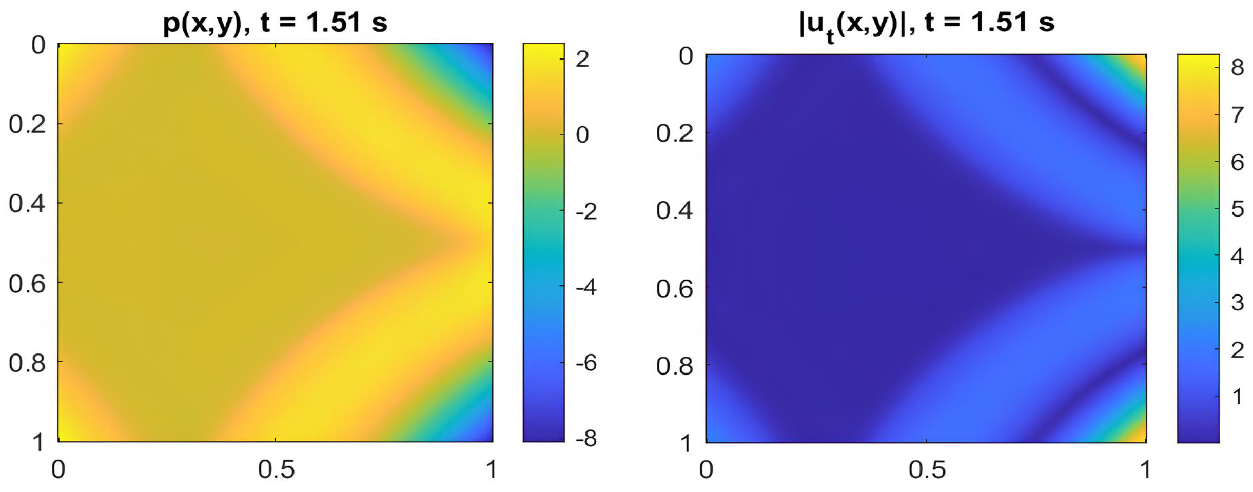
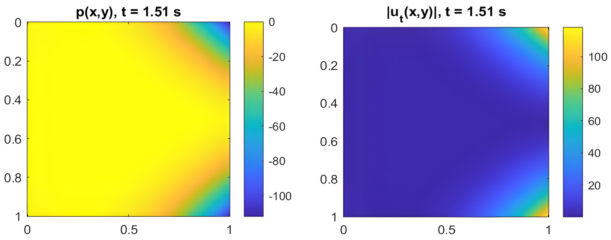
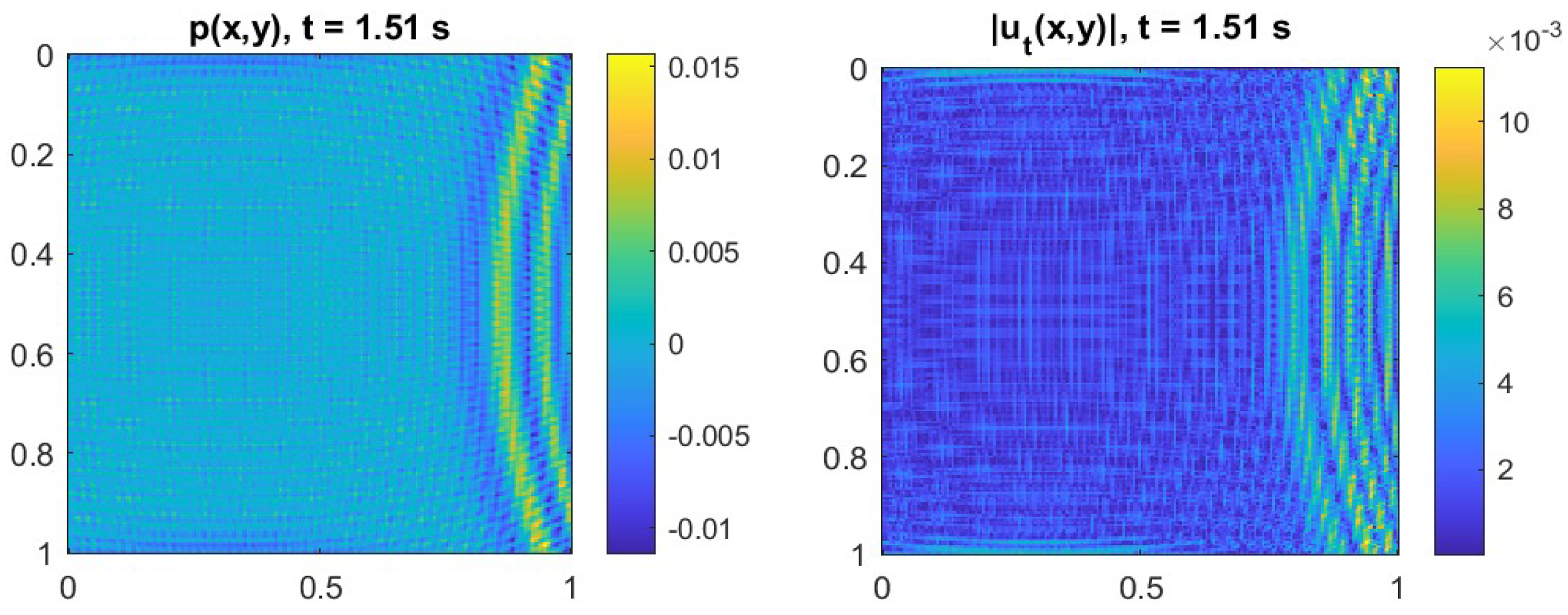
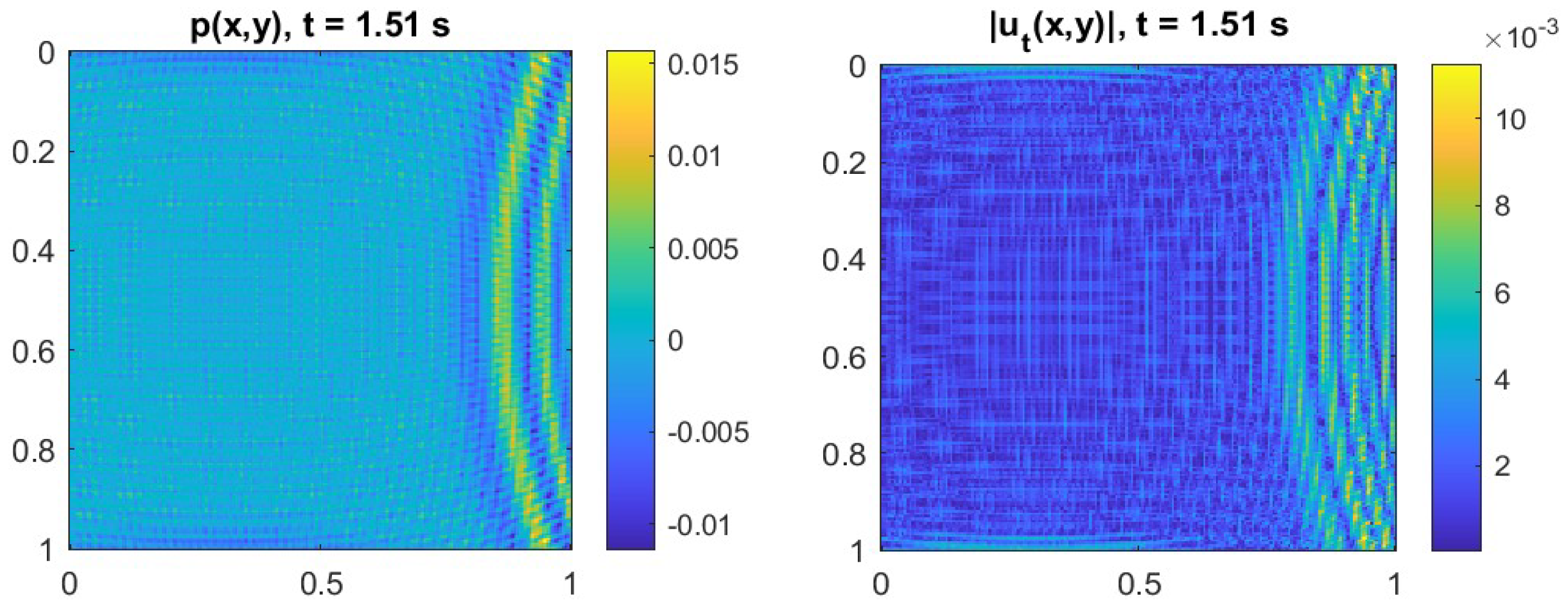
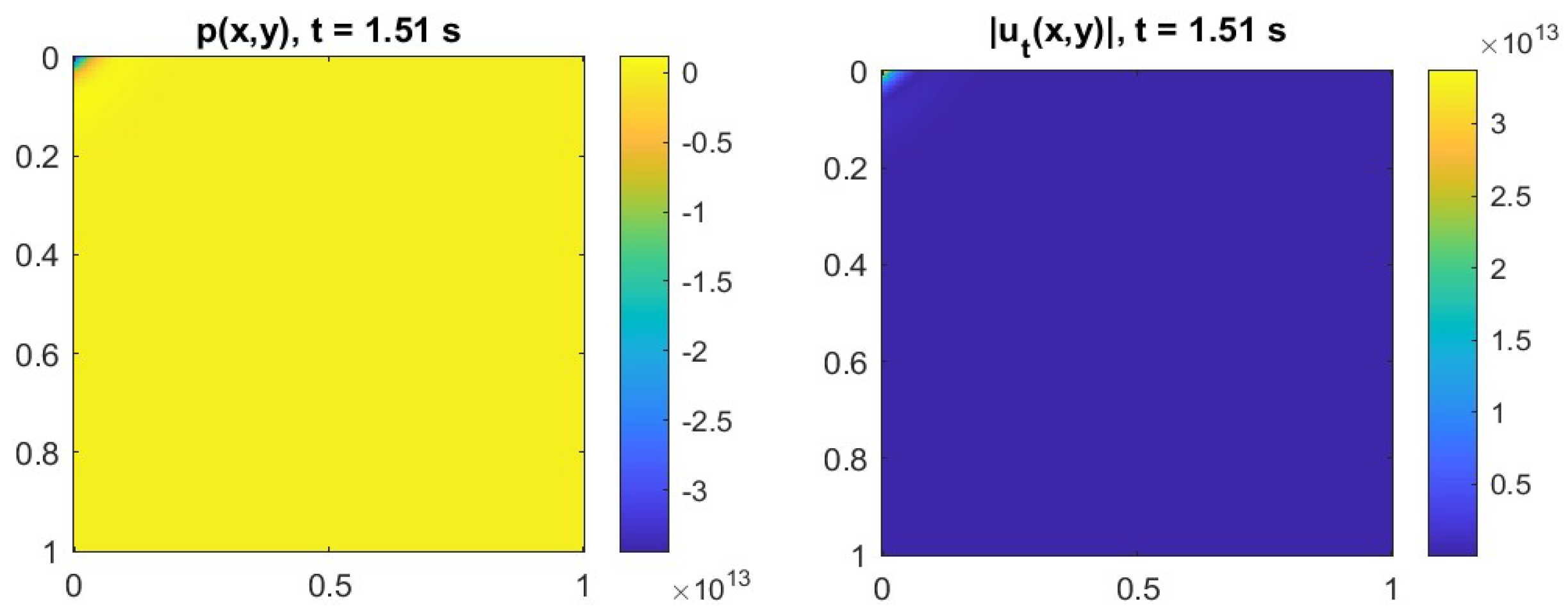
Figure 2 shows the spatial evolution of the pressure field p t ( x , y , t ) and velocity u t ( x , y , t ) in a medium containing a rigid inclusion. The round and compact shape of the defect induces significant reflection of the incident waves, highlighted by the localized pressure accumulation. The velocity remains almost zero inside the inclusion, confirming the restitutive elastic behavior and the energy stabilization theoretically predicted.
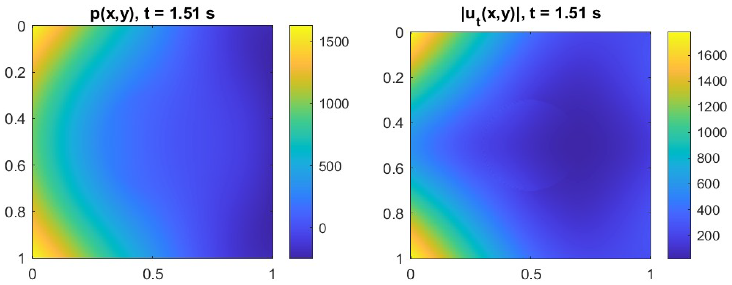
As for the closed cavities, they act as an elastic reservoir (see Figure 3). Pressure accumulates internally but does not dissipate: a regular deformation of the acoustic waves is observed without discontinuities or excessive amplification. Even in this scenario, the term μ i is positive, as suggested by the slight attenuation in energy followed by a recovery, confirming the temporary restitutive behavior of the defect.
Regarding Figure 4 (scarred microcrack), the velocity field shows a slight localized disturbance along the crack, but the pressure is distributed without generating strong gradients, in line with the theoretical interpretation that a healed microcrack does not significantly affect the overall coercivity.
In cases where open microcracks are present (Figure 5), pronounced discontinuities in the u t field are observed near the open crack, which acts as a zone of energy loss. The pressure field exhibits marked inhomogeneities with scattering and rarefaction effects. Energy decreases significantly over time, indicating a net dissipation associated with μ i < 0 . The numerical behavior fully reflects the classification of the defect as destabilizing.
If branched porosities are present in the concrete, the pressure field becomes fragmented by multiple porous zones arranged irregularly. The velocity exhibits complex oscillations, resulting in continuous and pronounced energy decay (see Figure 6). This confirms the highly dissipative nature of such a defect, where the branching amplifies wave dispersion, and μ i 0 .
Finally, in the presence of macroscopic inclusions—as opposed to rigid micro-inclusion—the size of the defect here is comparable to the wavelength. The dynamic behavior exhibits strong reflections and the emergence of local resonances, which negatively interfere with the orderly propagation of the wave. The u t field displays vortices and complex patterns, while the energy shows irregular drops, suggesting that despite the high stiffness, the defect’s scale makes it destabilizing and thus associated with μ i < 0 . Details are shown in Figure 7.
These figures visually confirm the theoretical results presented in the paper concerning the relationship between defect geometry, acoustic field behavior, and the sign of the parameter μ i . Each configuration exemplifies a different physical–mathematical scenario, reinforcing the validity of the proposed criterion for classifying defects based on their influence on the system’s coercivity.
In the present simulations, defects are modeled as regular geometric shapes to ensure computational efficiency and a clear energetic interpretation. Nevertheless, the framework is inherently flexible, as the localized term q t can accommodate arbitrary spatial distributions D i . This makes it possible to incorporate realistic morphologies derived from the X-ray or micro-CT imaging of concrete specimens. Future developments will focus on integrating voxel-based CT data into the numerical grid to enhance the physical realism of defect representation while preserving the same mathematical formulation.
It is recognized that in the present formulation, each defect is treated as an independent localized source term, and possible interactions among adjacent defects are not explicitly modeled. This simplification allows for the isolation of the energetic contribution of each defect and the clarification of its stabilizing or dissipative role within the material. However, the framework is general and can be extended to account for defect–defect interactions by introducing superposed or coupled source terms within the same domain. In such cases, the resulting interference—constructive or destructive—would naturally emerge from the coupled solution of the governing equations. Future developments will focus on investigating these collective effects, particularly in highly damaged or porous materials where multiple disturbances coexist and interact.

5.3. Energy Evolution and Defect Classification

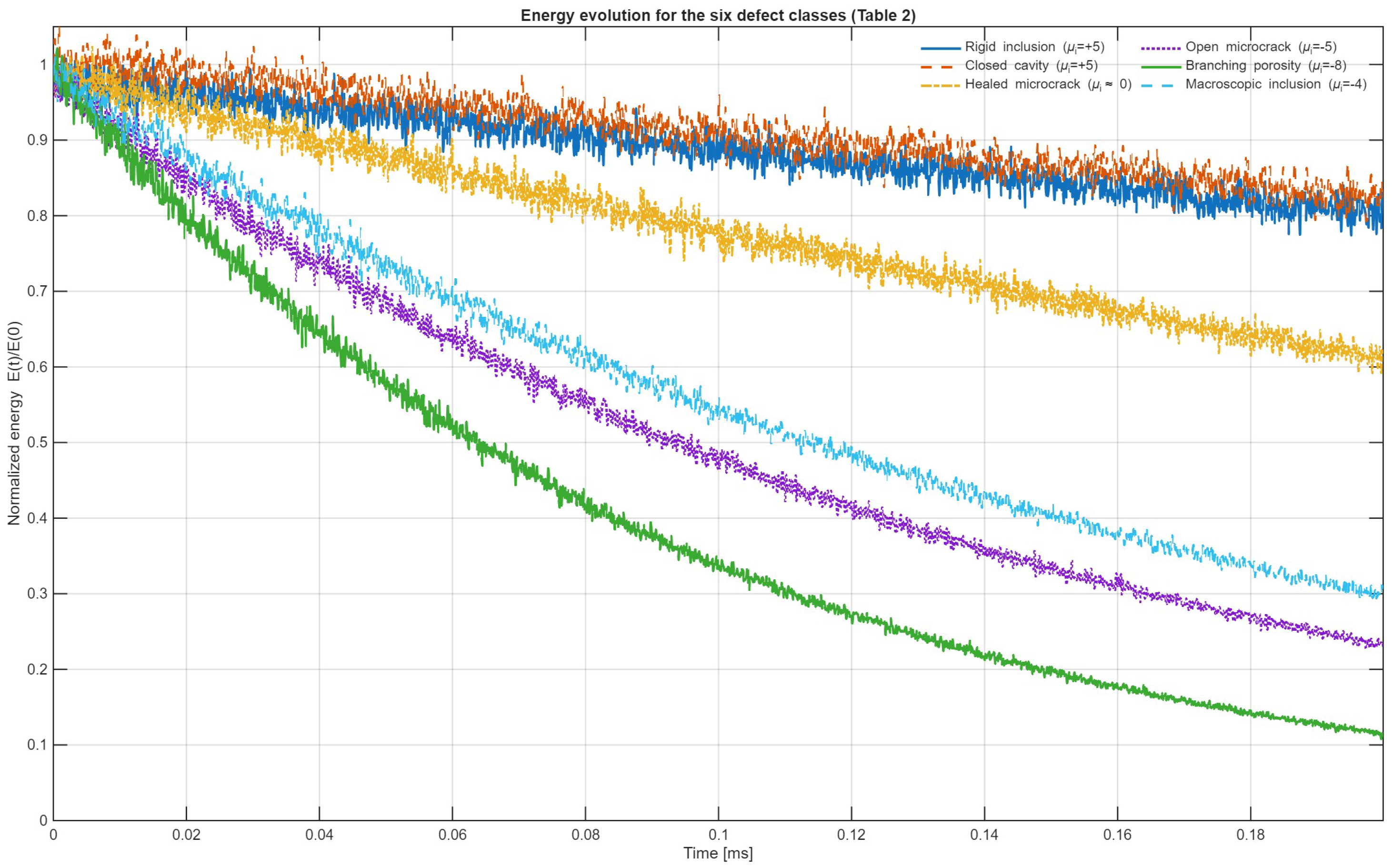
Figure 8 illustrates the temporal evolution of the normalized total energy, E ( t ) / E ( 0 ) , for the six defect configurations summarized in Table 2: rigid inclusion, closed cavity, healed microcrack, open microcrack, branching porosity, and macroscopic inclusion. The discrete total energy E ( t ) is computed at each time step according to Equation (37) as the sum of kinetic and potential contributions over the entire computational domain and is normalized by the initial energy E ( 0 ) evaluated at the first time step immediately after the source excitation.
The results clearly differentiate the energetic behavior associated with each defect class. For stabilizing defects ( μ i > 0 ), such as the rigid inclusion and the closed cavity, the normalized energy remains close to unity throughout the simulation, confirming an almost conservative regime characterized by high coercivity of the bilinear form. The healed microcrack ( μ i 0 ) exhibits a nearly constant energy trend with a very mild decay, indicating a quasi-neutral response and negligible impact on the global energy balance. In contrast, defects with negative μ i show progressively faster energy loss: the open microcrack ( μ i = 5 ) displays a marked monotonic decay; the branching porosity ( μ i = 8 ) produces a steep and continuous attenuation driven by multiple scattering; and the macroscopic inclusion ( μ i = 4 ) yields irregular oscillations and localized drops in energy caused by internal resonances and destabilizing reflections.
Overall, Figure 8 provides a unified energetic overview of all simulated configurations, visually confirming the theoretical classification of defects based on the sign of μ i : stabilizing ( μ i > 0 ) defects preserve coercivity and energy, and quasi-neutral ( μ i 0 ) defects maintain energetic equilibrium, while dissipative ( μ i < 0 ) defects induce attenuation and loss of stability. The correspondence between numerical and analytical trends validates the proposed variational formulation and demonstrates its capability to reproduce, within a single computational framework, the transition from conservative to dissipative regimes as a function of the local coercivity parameter.

5.4. Quantitative Comparison with Classical Models

To further assess the theoretical consistency and predictive capability of the proposed coercivity-based formulation, developed within the framework of the Lions theorem for time-dependent coupled hyperbolic problems, a quantitative comparison was carried out with two well-established reference models, the Biot-type poroelastic formulation [107] and the Kelvin–Voigt viscoelastic model, implemented according to the constitutive relation reported in [108], where E = 30 GPa and η = 1.2 × 10 9 Pa · s .
Both classical approaches describe attenuation as a global or averaged property of the medium—through permeability, porosity, or viscosity—whereas the present formulation introduces a localized energetic description by means of the forcing term q t ( x , t ) and the spatially varying coefficient μ i , which modulates the coercivity of the bilinear form as a dynamic function of the defect distribution. Numerical simulations were performed on a C25/30 concrete specimen with density ρ = 2400 kg / m 3 and wave speed c = 3500 m / s , using a Gaussian pulse centered at 40 kHz . All models were implemented with the same explicit finite-difference time-domain (FDTD) scheme and identical spatial discretization, satisfying the Courant–Friedrichs–Lewy (CFL) stability condition. The nonlinear compressibility coefficient was set to β = 0 to isolate the energetic contribution of defects—represented by μ i —from intrinsic material nonlinearities.
In the Biot-type poroelastic reference model, acoustic propagation in saturated or partially saturated porous media is governed by coupling between the solid skeleton and pore fluid through averaged macroscopic parameters (permeability k = 1.0 × 10 15 m 2 , porosity ϕ = 0.12 , and fluid bulk modulus K f = 2.2 GPa ). This approach reproduces global attenuation and dispersion effects but lacks explicit representation of localized energetic interactions. The Kelvin–Voigt model introduces frequency-dependent damping, assuming spatially homogeneous attenuation across the domain. In contrast, the proposed coercivity-based formulation extends the classical acoustic wave equation into an evolutionary hyperbolic system incorporating both the localized forcing term q t ( x , t ) and the spatially dependent coefficient μ i . This parameter directly modulates the local coercivity of the variational form, allowing defects to behave as energetic sources or sinks: μ i > 0 corresponds to stabilizing behavior, μ i 0 to quasi-neutral response, and μ i < 0 to dissipative conditions characterized by coercivity reduction and energy loss.
The quantitative agreement with the Biot and Kelvin–Voigt formulations, together with the enhanced interpretability provided by the local coefficient μ i , confirms the robustness of the proposed approach for the energetic characterization and classification of defects in concrete. The theoretical framework based on the Lions theorem ensures existence, uniqueness, and weak stability of the evolutionary problem, while the explicit dependence of coercivity on μ i enables the accurate modeling of the transition between conservative and dissipative regimes as a function of the local defect distribution (see Table 3).

6. Conclusions and Perspectives

This study develops a unified theoretical and computational framework for modeling acoustic wave propagation in discontinuous and porous materials, with direct application to structural concrete. The formulation, based on a coupled system of evolutionary equations, explicitly accounts for internal defects represented as localized energetic sources or sinks. A forcing term describing defect position, geometry, and mechanical properties enables a compact and physically consistent representation of their influence on the dynamic response.
The introduction of the coercivity coefficient provides a quantitative measure of each defect’s contribution to the system’s energetic balance and stability, allowing them to be classified as stabilizing, neutral, or dissipative. Numerical simulations confirm the theoretical predictions for typical discontinuities in concrete, such as inclusions, cavities, and microcracks, demonstrating that the coefficient governs the transition between energy confinement and dissipation.
The proposed framework establishes a rigorous mathematical link between microstructure and dynamic behavior, offering a quantitative tool for evaluating defect-induced energetic stability. These results lay the theoretical foundation for future applications in non-destructive testing, material design, and the diagnostic monitoring of concrete structures.
Future research will refine the correlation between defect geometry and coercivity through advanced variational formulations and improved numerical accuracy using higher-order or adaptive finite-element schemes. The model will also be extended to three dimensions and will reintroduce nonlinear terms to simulate progressive damage, hysteresis, and stiffness variations. Experimental validation, already planned within the ongoing CAIUS project, will involve controlled ultrasonic tests on concrete specimens with predefined defect geometries, enabling direct calibration of the coercivity coefficient.
Planned developments include inverse algorithms for defect localization and classification from acoustic measurements, as well as experimental validation on concrete specimens with controlled defects. This will allow for the calibration of the coercivity coefficients, currently defined theoretically, and confirm the model’s applicability to real diagnostic contexts. Integration with artificial intelligence tools will further support automated data interpretation and intelligent structural monitoring.
In summary, the framework establishes a consistent energetic link between defect morphology and acoustic stability through the coercivity coefficient, bridging microstructural irregularities and macroscopic wave behavior. Although experimental benchmarking remains a forthcoming objective, the present numerical validation provides a robust foundation for extending classical Biot-type and viscoelastic formulations toward more predictive and physically interpretable models.

Author Contributions

Conceptualization, M.V., M.C., F.L. and G.A.; methodology, M.V., M.C., F.L. and G.A.; software, M.V., M.C., F.L. and G.A.; validation, M.V., M.C., F.L. and G.A.; formal analysis, M.V., M.C., F.L. and G.A.; investigation, M.V., M.C., F.L. and G.A.; resources, M.V., M.C., F.L. and G.A.; data curation, M.V., M.C., F.L. and G.A.; writing—original draft preparation, M.V., M.C., F.L. and G.A.; writing—review and editing, M.V., M.C., F.L. and G.A.; visualization, M.V., M.C., F.L. and G.A.; supervision, M.V., M.C., F.L. and G.A.; project administration, M.V., M.C., F.L. and G.A.; funding acquisition, M.V., M.C., F.L. and G.A. All authors have read and agreed to the published version of the manuscript.

Funding

The authors acknowledge the support of (a) the research project PRIN 2022 No. 2022AZPLL8—“Integration of Artificial Intelligence and Ultrasonic Techniques for Monitoring Control and Self Repair of Civil Concrete Structures (CAIUS)”—and (b) the project FAIR ”Future Artificial Intelligence Research” (CUP H23C22000860006), funded by the European Union under ”NextGenerationEU”, by the Italian Ministry of University and Research (MUR), and by ”Italia Domani National Recovery and Resilience Plan (PNRR)”.

Institutional Review Board Statement

Not applicable.

Informed Consent Statement

Not applicable.

Data Availability Statement

The data presented in this study are available upon request from the corresponding author. The datasets presented in this article are not readily available because part of an industrial cooperation.

Conflicts of Interest

The authors declare no conflicts of interest.

Appendix A

Appendix A.1. Proof of Proposition 1

Let us consider the domain Ω R d , with H = L 2 ( Ω ) and V = H 1 ( Ω ) . Our goal is to show that V is densely embedded in H, that is, V ¯ H = H . Therefore, every function f H can be approximated in the H-norm by a sequence of functions f n V . To prove that V is dense in H, we show that every function u t H can be approximated by a sequence of functions in V. A well-known result from functional analysis states that the set of functions C c ( Ω ) , that is, smooth functions with compact support in Ω , is dense in L 2 ( Ω ) : C c ( Ω ) ¯ L 2 = L 2 ( Ω ) . Since C c ( Ω ) H 1 ( Ω ) = V , it follows that C c ( Ω ) ¯ H V ¯ H . Since C c ( Ω ) is dense in H, it follows that V is dense in H.
Let u t H . Since C c ( Ω ) is dense in H, there exists a sequence { ϕ n } C c ( Ω ) such that u t ϕ n H 0 for n . Since C c ( Ω ) V , we have that ϕ n V ; thus, the sequence { ϕ n } is a sequence in V that approximates u in the H-norm.

Appendix A.2. Proof of Proposition 2

We define the application T : H H as follows:
T ( f ) = F f , where F f ( v t ) = f , v t H = Ω f ( x ) v t ( x ) d x , v t H .
We prove that T is an isometric isomorphism. f , g H and α , β R , we have that
T ( α f + β g ) ( v t ) = F α f + β g ( v t ) = Ω ( α f ( x ) + β g ( x ) ) v t ( x ) d x = = α Ω f ( x ) v t ( x ) d x + β Ω g ( x ) v t ( x ) d x = α F f ( v t ) + β F g ( v t ) .
By applying the Cauchy–Schwarz inequality, we have that
| F f ( v t ) | = Ω f ( x ) v t ( x ) d x f H v t H .
And considering the sup over all v t H with v t H 1 , we obtain sup v t H 1 | F f ( v t ) | f H , so that the norm of the functional F f in H satisfies
F f H = sup v t H 0 | F f ( v t ) | v t H f H .
The above, with v t = f , becomes as follows:
F f H = sup v t H 0 | F f ( v t ) | v t H = sup v t H = 1 | F f ( v t ) | .
By substituting v t = f f H , we obtain
| F f ( v t ) | = Ω f ( x ) f ( x ) f H d x = f H 2 f H = f H .
Thus, F f H = f H , which proves that T is an isometry.
Let F H be a linear and continuous functional on H. By the Riesz Representation Theorem, there exists a unique f H such that F ( v t ) = f , v t H , v t H . Hence, every F H can be expressed as F f , proving that the map T : H H , f F f is surjective. If T ( f ) = 0 , then f , v t H = 0 for all v t H ; choosing v t = f yields f H 2 = 0 f = 0 , establishing injectivity. Therefore, T is an isometric isomorphism between H and H .

Appendix A.3. Proof of Proposition 3

The goal is to prove that H is densely embedded in V , that is, that Ω p t ρ · u t d x exists { F n } H such that F F n V 0 .
Let F V . By the Riesz Theorem, there exists a unique function g V such that F ( v ) = g , v t V , v t V . Since V is densely embedded in H, we can construct a sequence { g n } H such that g g n H 0 . We define the sequence of functionals F n H as F n ( v ) = g n , v t H . We need to verify that F n F V 0 n . By the definition of the norm in V and by applying the Cauchy–Schwarz inequality in the inner product of H,
F n F V = sup v V 1 | g n g , v H | g n g H v H .
Since V H , there exists a constant C > 0 such that v H C v V , so that
F n F V = sup v V 1 | g n g , v H | C g n g H .
Since g n g in H, we have that g n g H 0 , which implies that F n F V 0 . We have thus proven that every element of V can be arbitrarily well-approximated by a sequence of elements in H . This demonstrates the density of H in V , i.e., H ¯ V = V .

Appendix A.4. Proof of Proposition 5

To verify that a ( U , V ) is a bilinear form, we must check that it satisfies the following properties:
  • For every U , W , V V and for every λ R ,
    a ( U + W , V ) = a ( U , V ) + a ( W , V ) , a ( λ U , V ) = λ a ( U , V ) .
  • For every U , V , Z V and for every μ R ,
    a ( U , V + Z ) = a ( U , V ) + a ( U , Z ) , a ( U , μ V ) = μ a ( U , V ) .
Let U = ( p t , v t , u t ) and W = ( q t , w t , z t ) . Considering U + W = ( p t + q t , v t + w t , u t + z t ) , we get
a ( U + W , V ) = Ω ( ( v t + w t ) v t ) d x + + Ω c 2 ρ · 1 + β ( p t + q t ) ρ c 2 ( u t + z t ) v t d x + Ω ( p t + q t ) ρ · w t d x ,
from which we have
a ( U + W , V ) = Ω ( v t v t ) d x Ω w t v t d x + + Ω c 2 ρ · 1 + β p t ρ c 2 u t v t d x + Ω c 2 ρ · 1 + β q t ρ c 2 z t v t d x + + Ω p t ρ · w t d x + Ω q t ρ · w t d x .
Since each integral separates into two distinct terms, we obtain a ( U + W , V ) = a ( U , V ) + a ( W , V ) .
Let λ R . Consider
a ( λ U , V ) = Ω ( λ v t v t ) d x + Ω c 2 ρ · 1 + β ( λ p t ) ρ c 2 ( λ u t ) v t d x + + Ω ( λ p t ) ρ · w t d x = = λ Ω ( v t v t ) d x + Ω c 2 ρ · 1 + β p t ρ c 2 u t v t d x + Ω p t ρ · w t d x = λ a ( U , V ) .
Now, we prove the linearity with respect to the second argument. Let V = ( v t , w t , z t ) and Z = ( v t , w t , z t ) ; then for every μ R , consider
a ( U , V + Z ) = = Ω ( v t ( v t + v t ) ) d x + Ω c 2 ρ · 1 + β p t ρ c 2 u t ( v t + v t ) d x + + Ω p t ρ · ( w t + w t ) d x = = Ω ( v t v t ) d x Ω v t v t d x + + Ω c 2 ρ · 1 + β p t ρ c 2 u t v t d x + Ω c 2 ρ · 1 + β p t ρ c 2 u t v t d x + + Ω p t ρ · w t d x + Ω p t ρ · w t d x = a ( U , V ) + a ( U , Z ) .
Now, we verify homogeneity with respect to the second argument. For μ R ,
a ( U , μ V ) = = Ω ( v t μ v t ) d x + Ω c 2 ρ · 1 + β p t ρ c 2 u t ( μ v t ) d x + Ω p t ρ · ( μ w t ) d x = = μ Ω ( v t v t ) d x + Ω c 2 ρ · 1 + β p t ρ c 2 u t v t d x + Ω p t ρ · w t d x = μ a ( U , V ) .
Since we have verified additivity and homogeneity with respect to both arguments, we conclude that a ( U , V ) is a bilinear form.
a ( U , V ) is continuous if there exists a constant C > 0 such that
| a ( U , V ) | C U V V V , U , V V ,
where V is equipped with the norm U V = p t H 1 2 + v t L 2 2 + u t H ( div ) 2 1 / 2 , in which H ( div , Ω ) = { u t ( L 2 ( Ω ) ) d | · u t L 2 ( Ω ) } with the norm u t H ( div ) = u t L 2 2 + · u t L 2 2 1 / 2 . H ( div ) ensures that the term containing the divergence of u t is well-defined in the weak sense, allowing us to apply integration by parts without introducing unwanted boundary terms. We verify the continuity of a ( U , V ) by estimating each term separately. From the first term, v t v t , we can write Ω v t v t d x = Ω v t v t d x , from which, by applying the Cauchy–Schwarz inequality and taking into account that v t L 2 ( Ω ) , we obtain Ω v t v t d x v t L 2 V V .
As for the second term, using integration by parts allows us to write
Ω c 2 ρ · 1 + β p t ρ c 2 u t v t d x = Ω c 2 ρ 1 + β p t ρ c 2 u t · v t d x + Γ ( edge ) .
Under the assumption of homogeneous boundary conditions, the boundary term is zero. By applying the Cauchy–Schwarz inequality, it makes sense to write
Ω c 2 ρ 1 + β p t ρ c 2 u t · v t d x C u t H ( div ) v t H 1 .
Therefore,
Ω c 2 ρ · 1 + β p t ρ c 2 u t v t d x C u t H ( div ) V V .
By applying the Cauchy–Schwarz inequality to the third term, we have
Ω p t ρ · w t d x Ω p t ρ | w t | d x .
Since the density ρ is continuous and bounded, there exists a constant C such that p t ρ C p t L 2 . Therefore, since w t L 2 ,
Ω p t ρ · w t d x C p t H 1 V V .
Finally, by summing the results obtained, we get
| a ( U , V ) | C v t L 2 + u t H ( div ) + p t H 1 V V .
Since
U V = p t H 1 2 + v t L 2 2 + u t H ( div ) 2 1 / 2 ,
it follows that there exists a constant C > 0 such that | a ( U , V ) | C U V V V . Thus, a ( U , V ) is a bilinear and continuous form.

Appendix A.5. Proof of Proposition 6

We prove that U 1 , U 2 V and α , β R , A ( α U 1 + β U 2 ) = α A U 1 + β A U 2 . Using the definition of A, we write
A ( α U 1 + β U 2 ) = ( α v t 1 + β v t 2 ) c 2 ρ · 1 + β ( α p t 1 + β p t 2 ) ρ c 2 ( α u t 1 + β u t 2 ) ( α p t 1 + β p t 2 ) ρ = = α v t 1 c 2 ρ · 1 + β p t 1 ρ c 2 u t 1 p t 1 ρ + β v t 2 c 2 ρ · 1 + β p t 2 ρ c 2 u t 2 p t 2 ρ .
verifying the linearity of A.
We now show that A is continuous, that is, there exists a constant C > 0 such that A U V C U V , U V . From the definition of the dual norm, A U V = sup V V 1 | A U , V V , V | , and by substituting A U , we obtain
A U V = sup V V 1 Ω v t v t + c 2 ρ · 1 + β p t ρ c 2 u t v t + p t ρ · w t d x .
Firstly, we note that Ω v t v t d x v t L 2 v L 2 . Moreover, since V L 2 ( Ω ) , there exists a constant C V > 0 such that A U V = sup V V 1 | A U , V V , V | . Therefore,
Ω c 2 ρ · 1 + β p t ρ c 2 u t v t d x C u t H ( div ) V V .
Finally, Ω p t ρ · w d x C p t H 1 V V . By summing all the estimates, we obtain | a ( U , V ) | C U V V V . Therefore, A U V C U V . Therefore, A is continuous. A is dissipative if it satisfies A U , U V , V 0 , U V .
Alternatively, it is quasi-dissipative if there exists a constant λ 0 0 such that
A U , U V , V + λ 0 U H 2 0 , U V .
From definition (39), we can write
A U , U V , V = Ω v t 2 + c 2 ρ · 1 + β p t ρ c 2 u t v t + p t ρ · u t d x .
We observe that the term is always negative or zero, i.e., Ω v t 2 d x 0 . By applying integration by parts to the second term, we obtain
Ω · 1 + β p t ρ c 2 u t v t d x = Ω 1 + β p t ρ c 2 u t · v t d x .
Under homogeneous boundary conditions, the boundary term vanishes. The sign of this term is not guaranteed.
As for the third term, by applying the Cauchy–Schwarz inequality and since ρ is bounded by positive constants, we obtain Ω p t ρ · u t d x p t ρ L 2 u t L 2 . Therefore, there exists a constant C ρ > 0 such that p t ρ L 2 C ρ p t H 1 . So, Ω p t ρ · u t d x C ρ p t H 1 u t H ( div ) . Since the first term is always negative and the other terms have an indefinite sign, A is quasi-dissipative, that is, A U , U V , V + λ 0 U H 2 0 .

Appendix A.6. Proof of Theorem 2

We first prove that F L 2 ( 0 , T ; V ) . By definition, this space consists of functions F : [ 0 , T ] V such that
F L 2 ( 0 , T ; V ) 2 = 0 T F ( t ) V 2 d t < , F ( t ) V = sup V V 1 | F ( t ) , V V , V | .
Given F, the duality pairing reads
F , V V , V = Ω c 2 ρ Q m v t d x + Ω q ρ w t d x .
By applying the Cauchy–Schwarz inequality, we have
| Ω c 2 ρ Q m v t d x | c 2 ρ max Q m L 2 v t L 2 C V c 2 ρ max Q m L 2 V V ,
and
| Ω q ρ w d x | C ρ q t L 2 w t L 2 C ρ C V q t L 2 V V ,
where C V and C ρ depend on the embedding V L 2 ( Ω ) and the bounds on ρ . Hence,
F ( t ) V C V c 2 ρ max Q m L 2 + C ρ q t L 2 .
Squaring and integrating over ( 0 , T ) yield
0 T F ( t ) V 2 d t C V 2 2 c 4 ρ max 2 0 T Q m L 2 2 d t + 2 C ρ 2 0 T q t L 2 2 d t ,
which is finite since Q m , q L 2 ( 0 , T ; L 2 ( Ω ) ) . Thus, F L 2 ( 0 , T ; V ) . Next, we assess coercivity. Setting V = U in (39) gives
a ( U , U ) = Ω v t 2 + c 2 ρ · 1 + β p t ρ c 2 u t v t + p t ρ · u t d x .
The first term is nonpositive, i.e.,
Ω v t 2 d x 0 ,
so a ( U , U ) cannot be strictly positive. Integrating the second term by parts (assuming homogeneous boundary conditions), we have
Ω c 2 ρ · 1 + β p t ρ c 2 u t v t d x = Ω c 2 ρ 1 + β p t ρ c 2 u t · v t d x ,
whose sign is indefinite since v t may change sign. Similarly, for the last term,
| Ω p t ρ · u t d x | C p t H 1 u t H ( div ) ,
which again lacks definite sign. Hence, although a ( U , V ) is continuous, it is not coercive because a ( U , U ) may be nonpositive. Consequently, Theorem 1 cannot be directly applied, despite the fulfillment of the remaining hypotheses.

References

  1. Li, E.D.; Shiying, T.; Wang, Z.; Zerfu, K. Eco-Friendly Fibre Reinforced Geopolymer Concrete: A Critical Review on the Microstructure and Long-Term Durability Properties. Case Stud. Constr. Mater. 2022, 16, e00894. [Google Scholar] [CrossRef]
  2. Wang, J.; Zhu, L.; Wan, D.; Xue, Y. Research Progress and Trend Analysis of Solid Waste Resource Utilization in Geopolymer Concrete. Buildings 2025, 15, 3370. [Google Scholar] [CrossRef]
  3. Burrascano, P.; Di Schino, A.; Versaci, M. Efficient Estimation of Synthetic Indicators for the Assessment of Nonlinear Systems Quality. Appl. Sci. 2024, 14, 9259. [Google Scholar] [CrossRef]
  4. Angiulli, G.; Versaci, M.; Burrascano, P.; Laganá, F. A Data-Driven Gaussian Process Regression Model for Concrete Complex Dielectric Permittivity Characterization. Sensors 2025, 25, 6350. [Google Scholar] [CrossRef]
  5. Zhang, Y.; Dai, S. Algorithm for Acoustic Wavefield in Space–Wavenumber Domain of Vertically Heterogeneous Media Using NUFFT. Mathematics 2025, 13, 571. [Google Scholar] [CrossRef]
  6. Abdollahi-Mamoudan, F.; Ibarra-Castanedo, C.; Maldague, X.P.V. Non-Destructive Testing and Evaluation of Hybrid and Advanced Structures: A Comprehensive Review of Methods, Applications, and Emerging Trends. Sensors 2025, 25, 3635. [Google Scholar] [CrossRef]
  7. Angiulli, G.; Burrascano, P.; Ricci, M.; Versaci, M. Advances in the Integration of Artificial Intelligence and Ultrasonic Techniques for Monitoring Concrete Structures: A Comprehensive Review. J. Compos. Sci. 2024, 8, 531. [Google Scholar] [CrossRef]
  8. Versaci, M.; Laganà, F.; Manin, L.; Angiulli, G. Soft Computing and Eddy Currents to Estimate and Classify Delaminations in Biomedical Device CFRP Plates. J. Electr. Eng. 2024, 76, 72–79. [Google Scholar] [CrossRef]
  9. Simone, G.; Morabito, F.C.; Polikar, R.; Ramuhalli, P.; Udpa, L.; Udpa, S. Feature Extraction Techniques for Ultrasonic Signal Classification. Int. J. Appl. Electromagn. Mech. 2002, 15, 291–294. [Google Scholar] [CrossRef]
  10. Wang, H. Research on Ultrasonic Nondestructive Testing Method Based on Multimodal Sensor Fusion and Deep Learning. In Proceedings of the 8th International Conference on Advanced Algorithms and Control Engineering (ICAACE 2025), Shanghai, China, 21–23 March 2025; pp. 1–6. [Google Scholar] [CrossRef]
  11. Wang, H.; Jongmanns, M. Active Ultrasonic Measurements for Machine Condition Monitoring. In Proceedings of the 2025 IEEE International Instrumentation and Measurement Technology Conference (I2MTC), Chemnitz, Germany, 19–22 May 2025; pp. 1–6. [Google Scholar] [CrossRef]
  12. Lei, Y.; Liu, H.; Wang, W.; Wu, C.; Zhang, M.; He, L.; Liu, P.; Zhou, L.; Li, Y. Fuzzy Logic-Based Control of Superconducting Closed-Loop Current with a Linear-Motor Type Flux Pump. Cryogenics 2025, 150, 104148. [Google Scholar] [CrossRef]
  13. Cacciola, M.; Morabito, F.C.; Polimeni, D.; Versaci, M. Fuzzy Characterization of Flawed Metallic Plates with Eddy Current Tests. Prog. Electromagn. Res. 2007, 72, 241–252. [Google Scholar] [CrossRef]
  14. Gel’atko, M.; Hatala, M.; Botko, F.; Vandžura, R.; Hajnyš, J. Eddy Current Testing of Artificial Defects in 316L Stainless Steel Samples Made by Additive Manufacturing Technology. Materials 2022, 15, 6783. [Google Scholar] [CrossRef]
  15. Versaci, M. Fuzzy Approach and Eddy currents NDT/NDE Devices in Industrial Applications. Electron. Lett. 2016, 52, 943–945. [Google Scholar] [CrossRef]
  16. Fernandes, N.A.T.C.; Sharma, S.; Arieira, A.; Hinckel, B.; Silva, F.; Leal, A.; Carvalho, Ó. Experimental Validation of Time-Explicit Ultrasound Propagation Models with Sound Diffusivity or Viscous Attenuation in Biological Tissues Using COMSOL Multiphysics. Bioengineering 2025, 12, 946. [Google Scholar] [CrossRef] [PubMed]
  17. Bonfiglio, P. A mechanical relaxation test for the determination of the frequency dependent complex modulus of linear viscoelastic materials. npj Acoust. 2025, 1, 21. [Google Scholar] [CrossRef]
  18. Pawlik, L.; Wilk-Jakubowski, J.L.; Frej, D.; Wilk-Jakubowski, G. Applications of Computational Mechanics Methods Combined with Machine Learning and Neural Networks: A Systematic Review (2015–2025). Appl. Sci. 2025, 15, 10816. [Google Scholar] [CrossRef]
  19. Isidori, G.; Wilsch, F.; Wyler, D. The Standard Model Effective Field Theory at Work. Rev. Mod. Phys. 2024, 96, 015006. [Google Scholar] [CrossRef]
  20. Ghasemi, M.; Vetro, C.; Zhang, Z. Dirichlet μ-Parametric Differential Problem with Multivalued Reaction Term. Mathematics 2025, 13, 1295. [Google Scholar] [CrossRef]
  21. Younas, U.; Muhammad, J.; Ismael, H.F.; Sulaiman, T.A.; Emadifar, H.; Ahmed, K.K. The New Combined Kairat-II-X Differential Equation: Diversity of Solitary Wave Structures via New Techniques. J. Nonlinear Math. Phys. 2025, 32, 55. [Google Scholar] [CrossRef]
  22. Izadi, M.; Srivastava, H.M.; Kamandar, M. The LDG Finite-Element Method for Multi-Order FDEs: Applications to Circuit Equations. Fractal Fract. 2025, 9, 230. [Google Scholar] [CrossRef]
  23. Mosquera-Lois, I.; Kavanagh, S.R.; Klarbring, J.; Tolborg, K.; Walsh, A. Imperfections Are Not 0 K: Free Energy of Point Defects in Crystals. Chem. Soc. Rev. 2023, 52, 5812–5826. [Google Scholar] [CrossRef]
  24. Alsuhaibani, E. Nondestructive Testing of Externally Bonded FRP Concrete Structures: A Comprehensive Review. Polymers 2025, 17, 1284. [Google Scholar] [CrossRef]
  25. Elmoghazy, Y.H.; Safaei, B.; Asmael, M.; Sahmani, S.; Zeeshan, Q.; Qin, Z. Computational modelling and analysis of effect of viscoelastic materials on damping and vibrational behaviors of composite structures—An extensive review. Arch. Comput. Methods Eng. 2024, 31, 2611–2662. [Google Scholar] [CrossRef]
  26. Georgievskii, D. Table of Postulates of Continuum Mechanics and Principles of Forming Its Rows. J. Appl. Mech. Tech. Phys. 2024, 65, 1182–1188. [Google Scholar] [CrossRef]
  27. Römer, U.; Hartmann, S.; Tröger, J.A.; Anton, D.; Wessels, H.; Flaschel, M.; De Lorenzis, L. Reduced and all-at-once approaches for model calibration and discovery in computational solid mechanics. Appl. Mech. Rev. 2025, 77, 040801. [Google Scholar] [CrossRef]
  28. Gräßle, B.; Hiptmair, R.; Sauter, S. Stable Skeleton Integral Equations for General-Coefficient Helmholtz Transmission Problems. arXiv 2025, arXiv:2507.00991. [Google Scholar]
  29. Skvortsov, A.; MacGillivray, I.; Godin, O.A. Acoustic Waves in a Perforated Cylinder. J. Acoust. Soc. Am. 2025, 157, 1880–1888. [Google Scholar] [CrossRef]
  30. Raabe, D.; Mianroodi, J.R.; Neugebauer, J. Accelerating the design of compositionally complex materials via physics-informed artificial intelligence. Nat. Comput. Sci. 2023, 3, 198–209. [Google Scholar] [CrossRef]
  31. Hassani, S.; Dackermann, U. A systematic Review of Advanced Sensor Technologies for Non-Destructive Testing and Structural Health Monitoring. Sensors 2023, 23, 2204. [Google Scholar] [CrossRef]
  32. Ribeiro Junior, R.F.; Gomes, G.F. On the Use of Machine Learning for Damage Assessment in Composite Structures: A Review. Appl. Compos. Mater. 2024, 31, 1–37. [Google Scholar] [CrossRef]
  33. Zhang, P.; Ding, J.; Guo, J.; Wang, F. Fractal Analysis of Cement-Based Composite Microstructure and Its Application in Evaluation of Macroscopic Performance of Cement-Based Composites: A Review. Fractal Fract. 2024, 8, 304. [Google Scholar] [CrossRef]
  34. Khan, M.M.; Iqbal, M.A. Dynamic Increase Factor of Concrete Subjected to Compression and Tension by Using Split Hopkinson Pressure Bar Setup: Overview. Mech. Solids 2023, 58, 2115–21231. [Google Scholar] [CrossRef]
  35. Li, S.; Zhang, Z.; Zhang, Q.; Yao, H.; Li, X.; Mi, J.; Wang, H. Breakthrough Underwater Physical Environment Limitations on Optical Information Representations: An Overview and Suggestions. J. Mar. Sci. Eng. 2024, 12, 1055. [Google Scholar] [CrossRef]
  36. Le Clainche, S.; Ferrer, E.; Gibson, S.; Cross, E.; Parente, A.; Vinuesa, R. Improving Aircraft performance using machine learning: A review. Aerosp. Sci. Technol. 2023, 138, 108354. [Google Scholar] [CrossRef]
  37. Siddique, J.L.; Ahmed, A.; Aziz, A.; Khalique, C.M. A Review of Mixture Theory for Deformable Porous Media and Applications. Appl. Sci. 2017, 7, 917. [Google Scholar] [CrossRef]
  38. Giorgio, I.; Galantucci, L.; Della Corte, A.; Del Vescovo, D. Piezo-Electromechanical Smart Materials with Distributed Arrays of Piezoelectric Transducers: Current and Upcoming Applications. Int. J. Appl. Electromagn. Mech. 2015, 47, 1051–1084. [Google Scholar] [CrossRef]
  39. Wang, E.; Carcion, J.M.; Liu, Y. Reflection and Transmission of Plane Elastic Waves at an Interface Between two Double-Porosity Media: Effect of Local Fluid Flow. Surv. Geophys. 2020, 41, 283–322. [Google Scholar] [CrossRef]
  40. Piroddi, L.; Abu Zeid, N.; Calcina, S.V.; Capizzi, P.; Capozzoli, L.; Catapano, I.; Cozzolino, M.; D’Amico, S.; Lasaponara, R.; Tapete, D. Imaging Cultural Heritage at Different Scales: Part I, the Micro-Scale (Manufacts). Remote Sens. 2023, 15, 2586. [Google Scholar] [CrossRef]
  41. Ferrari, A.; Luna, B.Q.; Spickermann, A.; Travelletti, J.; Krzeminska, D.; Eichenberger, J.; van Asch, T.; van Beek, R.; Bogaard, T.; Malet, J.-P.; et al. Techniques for the Modelling of the Process Systems in Slow and Fast-Moving Landslides. Mt. Risks Predict. Manag. Gov. 2014, 34, 82–129. [Google Scholar] [CrossRef]
  42. Aslam, M.A.; Li, Z. A Sustainable Approach to Boost Resilience in Fast-Moving Consumer Goods: The Critical Role of Suppliers and Transportation Capacity Explored Through PLS-SEM and NCA. Sustainability 2025, 17, 2625. [Google Scholar] [CrossRef]
  43. Zhan, L.; Liu, B.; Zhang, Y.; Lu, H. Rock Physics Modeling of Acoustic Properties in Gas Hydrate-Bearing Sediment. J. Mar. Sci. Eng. 2022, 10, 1076. [Google Scholar] [CrossRef]
  44. Smit, T.H. Finite Element Models of Osteocytes and Their Load-Induced Activation. Curr. Osteoporos. Rep. 2022, 20, 127–140. [Google Scholar] [CrossRef]
  45. Fuhg, J.N.; Anantha Padmanabha, G.; Bouklas, N.; Bahmani, B.; Sun, W.; Vlassis, N.N.; Flaschel, M.; Carrara, P.; De Lorenzis, L. A Review on Data-Driven Constitutive Laws for Solids. Arch. Comput. Methods Eng. 2025, 32, 1841–1883. [Google Scholar] [CrossRef]
  46. de Oliveira, D.; Gonçalves, M.V.; Ribeiro, G.M.; da Costa, A.L.S.; Regueiras, L.; Silva, T.; de Jesus, A.; Malcher, L.; Ziberov, M. On the Use of Compressed Air and Synthetic Biodegradable Cutting Fluid to Enhance the Surface Quality of WAAM–CMT Manufactured Low-Alloy Steel Parts During Post-Processing Milling with Different Cooling–Lubrication Strategies. J. Manuf. Mater. Process. 2025, 9, 193. [Google Scholar] [CrossRef]
  47. Liu, L.; Zhou, M.; Li, X.; Jin, L.; Su, G.; Mo, Y.; Li, L.; Zhu, H.; Tian, Y. Research Progress in Application of 2D Materials in Liquid-Phase Lubrication System. Materials 2018, 11, 1314. [Google Scholar] [CrossRef]
  48. Banihashemi, S.; Assadimoghadam, A.; Hajirasouli, A.; LeNguyen, K.; Mohandes, S.R. Parametric design in construction: A new paradigm for quality management and defect reduction. Int. J. Constr. Manag. 2025, 25, 1534–1551. [Google Scholar] [CrossRef]
  49. Faris, N.; Zayed, T.; Fares, A. Review of Condition Rating and Deterioration Modeling Approaches for Concrete Bridges. Buildings 2025, 15, 219. [Google Scholar] [CrossRef]
  50. Hoxha, E.; Feng, J.; Sengupta, A.; Kirakosian, D.; He, Y.; Shang, B.; Gjinofci, A.; Xiao, J. Contrastive Learning for Robust Defect Mapping in Concrete Slabs Using Impact Echo. Constr. Build. Mater. 2025, 461, 139829. [Google Scholar] [CrossRef]
  51. Liu, W.K.; Li, S.; Park, H. Eighty Years of the Finite Element Method: Birth, Evolution, and Future. Arch. Comput. Methods Eng. 2022, 29, 4431–4453. [Google Scholar] [CrossRef]
  52. Hilal, W.; Gadsden, S.A.; Yawney, J. Cognitive Dynamic Systems: A Review of Theory, Applications, and Recent Advances. Proc. IEEE 2023, 111, 575–622. [Google Scholar] [CrossRef]
  53. Laganà, F.; Pullano, S.; Angiulli, G.; Versaci, M. Optimized Analytical-Numerical Procedure for Ultrasonic Sludge Treatment for Agricultural Use. Algorithms 2024, 17, 592. [Google Scholar] [CrossRef]
  54. Versaci, M.; Palumbo, A. Magnetorheological Fluids: Qualitative Comparison Between a Mixture Model in the Extended Irreversible Thermodynamics Framework and an Herschel–Bulkley Experimental Elastoviscoplastic Model. Int. J. Non-Linear Mech. 2020, 118, 103288. [Google Scholar] [CrossRef]
  55. Bilotta, G.; Barrile, V.; Bibbò, L.; Meduri, G.M.; Versaci, M.; Angiulli, G. Enhancing Land Cover Classification: Fuzzy Similarity Approach Versus Random Forest. Symmetry 2025, 17, 929. [Google Scholar] [CrossRef]
  56. Huang, H.; Chen, F.; Cao, K.; Zhang, X.; Li, R. Damage Evolution Characteristics of Steel-Fiber-Reinforced Cellular Concrete Based on Acoustic Emission. Buildings 2025, 15, 229. [Google Scholar] [CrossRef]
  57. Zhang, W.; Liu, D.; Tang, Y.; Jian, Y. Compression Damage Precursors of Silane-Protected Concrete Under Sulfate Erosion Based on Acoustic Emission Characterization. Fractal Fract. 2025, 9, 254. [Google Scholar] [CrossRef]
  58. Mohammad, M.; Paivo, K.; Marjaana, K.; Zahra, A.; Lidija, K.; Vilma, D.; Ahmad, A.; Mirja, I. Im pacts of Casting Scales and Harsh Conditions on the Thermal, Acoustic, and Mechanical Properties of Indoor Acoustic Panels Made with Fiber-Reinforced Alkali-Activated Slag Foam Concretes. Materials 2019, 12, 825. [Google Scholar] [CrossRef] [PubMed]
  59. Zalegowski, K. Pore Structure Influence on Properties of Air-Entrained Concrete. Materials 2025, 18, 2885. [Google Scholar] [CrossRef]
  60. Beskopylny, A.N.; Shcherban’, E.M.; Stel’makh, S.A.; Elshaeva, D.; Chernil’nik, A.; Razveeva, I.; Panfilov, I.; Kozhakin, A.; Madenci, E.; Aksoylu, C.; et al. Porosity Analysis and Thermal Conductivity Prediction of Non-Autoclaved Aerated Concrete Using Convolutional Neural Network and Numerical Modeling. Buildings 2025, 15, 2442. [Google Scholar] [CrossRef]
  61. Singh, M.P.; Singh, R.K. Correlation Between Ultrasonic Velocity, Surface Tension, Density and Viscosity of Ionic Liquids. Fluid Phase Equilibria 2011, 30, 1–6. [Google Scholar] [CrossRef]
  62. Aghaei, H.; Penkov, G.M.; Solomoichenko, D.A.; Toorajipour, A.; Petrakov, D.G.; Jafarpour, H. Density-Dependent Relationship Between Changes in Ultrasonic Wave Velocities, Effective Stress, and Petrophysical-Elastic Properties of Sandstone. Ultrasonics 2023, 132, 106985. [Google Scholar] [CrossRef] [PubMed]
  63. Lay-Ekuakille, A.; Palamara, I.; Caratelli, D.; Morabito, F.C. Experimental Infrared Measurements for Hydrocarbon Pollutant Determination in Subterranean Waters. Rev. Sci. Instruments 2013, 84, 015103. [Google Scholar] [CrossRef] [PubMed]
  64. Ciarlet, P.; Jamelot, E. Explicit T-coercivity for the Stokes problem: A coercive finite element discretization. Comput. Math. Appl. 2025, 188, 137–159. [Google Scholar] [CrossRef]
  65. Mohapatra, A.R.D.; Deka, B. A non conforming temporal stabilizer-free finite element method for non-coercive eddy current problems. J. Comput. Appl. Math. 2026, 474, 116984. [Google Scholar] [CrossRef]
  66. Edwards, K.A.T.; Al-Abed, S.H.; Hosseini, S.; Brake, N.A. Properties of a Magnetic Concrete Core Transformer for Application in Wireless Power Transfer Systems. Constr. Build. Mater. 2019, 227, 117041. [Google Scholar] [CrossRef]
  67. Fomenko, E.V.; Knyazev, Y.V.; Akimochkina, G.V.; Semenov, S.V.; Yumashev, V.V.; Solovyov, L.A.; Anshits, N.N.; Bayukov, O.A.; Anshits, A.G. Mössbauer Research and Magnetic Properties of Dispersed Microspheres from High-Calcium Fly Ash. Magnetochemistry 2025, 11, 72. [Google Scholar] [CrossRef]
  68. Mustafa Mohamed, A.; Tayeh, B.A.; Ahmed, T.I.; Bashir, M.O.; Tobbala, D.E. Influence of nano-silica and nano-ferrite particles on mechanical and durability of sustainable concrete: A review. Nanotechnol. Rev. 2025, 14, 20250151. [Google Scholar] [CrossRef]
  69. Tabish, M.; Zaheer, M.M.; Baqi, A. Effect of nano-silica on mechanical, microstructural and durability properties of cement-based materials: A review. J. Build. Eng. 2023, 65, 105676. [Google Scholar] [CrossRef]
  70. Ventura, G.; Díaz, C.; Morales, H.; Brigola, R. Application Examples for Distributions. In Fourier Analysis and Distributions; Texts in Applied Mathematics; Springer: Cham, Switzerland, 2025; Volume 79. [Google Scholar] [CrossRef]
  71. Vala, J.; Tomáš, J. Damage Behaviour of Quasi-Brittle Composites: Mathematical and Computational Aspects. Appl. Sci. 2025, 15, 4214. [Google Scholar] [CrossRef]
  72. Spalvier, A.; Sánchez, J.; Pérez, N. 3D Modeling of Ultrasonic Wave Propagation in Pervious Concrete. J. Nondestruct. Eval. 2025, 44, 104. [Google Scholar] [CrossRef]
  73. Liu, C.; Hao, H.; Liu, J. Mesoscopic numerical investigation on wave attenuation in meta-concrete with cubic engineered aggregates. Eng. Struct. 2025, 344, 121360. [Google Scholar] [CrossRef]
  74. Korjakins, A.; Sahmenko, G.; Lapkovskis, V. A Short Review of Recent Innovations in Acoustic Materials and Panel Design: Emphasizing Wood Composites for Enhanced Performance and Sustainability. Appl. Sci. 2025, 15, 4644. [Google Scholar] [CrossRef]
  75. Wilk-Jakubowski, J.L.; Pawlik, L.; Frej, D.; Wilk-Jakubowski, G. The Evolution of Machine Learning in Vibration and Acoustics: A Decade of Innovation (2015–2024). Appl. Sci. 2025, 15, 6549. [Google Scholar] [CrossRef]
  76. Rostampour, M.A.; Mostofinejad, D.; Bahmani, H.; Mostafaei, H. Crack Assessment Using Acoustic Emission in Cement-Free High-Performance Concrete Under Mechanical Stress. J. Compos. Sci. 2025, 9, 380. [Google Scholar] [CrossRef]
  77. Nitka, M.; Rucka, M. 3D DEM Modelling of Acoustic Emission in Concrete: Insights into Elastic Waves Initiated by Microcracks. Ultrasonics 2025, 150, 107599. [Google Scholar] [CrossRef] [PubMed]
  78. Baktheer, A.; Aguilar, M.; Chudoba, R. Comprehensive Review of the Microplane Framework for Constitutive Modeling Focused on Homogenization Approaches. Arch. Comput. Methods Eng. 2025. [Google Scholar] [CrossRef]
  79. Kabantsev, O.; Kovalev, M. Failure Mechanisms and Parameters of Elastoplastic Deformations of Anchorage in a Damaged Concrete Base under Seismic Loading. Buildings 2022, 12, 78. [Google Scholar] [CrossRef]
  80. Al-Mistarehi, B.; Al-Omari, A.; Taamneh, M.; Imam, R.; Khafaja, D.A.-D. The effects of adding nano clay and nano zinc oxide on asphalt cement rheology. J. King Saud Univ.-Eng. Sci. 2023, 35, 260–269. [Google Scholar] [CrossRef]
  81. Bacharz, M.; Bacharz, K.; Trąmpczyński, W. Impact of Early-Age Curing and Environmental Conditions on Shrinkage and Microcracking in Concrete. Materials 2025, 18, 3185. [Google Scholar] [CrossRef]
  82. Alshoaibi, A.M.; Fageehi, Y.A. Advances in Finite Element Modeling of Fatigue Crack Propagation. Appl. Sci. 2024, 14, 9297. [Google Scholar] [CrossRef]
  83. Ruiz Martínez, J.D.; Ríos, J.D.; Pérez-Soriano, E.M.; Cifuentes, H.; Leiva, C. Enhancing the matrix–fiber bond in ultra-high-performance fiber-reinforced concrete using a high performance plasticizer. Impact on the flowability, physical and mechanical properties. Constr. Build. Mater. 2025, 470, 140683. [Google Scholar] [CrossRef]
  84. Demiral, M. Strength in Adhesion: A Multi-Mechanics Review Covering Tensile, Shear, Fracture, Fatigue, Creep, and Impact Behavior of Polymer Bonding in Composites. Polymers 2025, 17, 2600. [Google Scholar] [CrossRef] [PubMed]
  85. Li, J.; Chen, Z. Research on Dry Coupling Technology in the Ultrasonic Non-Destructive Testing of Concrete. Micromachines 2025, 16, 72. [Google Scholar] [CrossRef] [PubMed]
  86. Scavone, M.; Katicha, S.W.; Flintsch, G.W.; Amarh, E. On the TSD Deflection Velocity Measurements: A Revision to the Current State of the Art and Discussion over Its Applicability for Concrete Pavement Assessment. Int. J. Pavement Eng. 2023, 24, 2138881. [Google Scholar] [CrossRef]
  87. Zhang, J.; Pang, H.; Xing, Y. Mechanistic Analysis of Electromagnetic Ultrasonic Transverse Wave Detection of Steel Plates in High-Temperature Multi-Physical Environments. Measurement 2025, 245, 116601. [Google Scholar] [CrossRef]
  88. Aksoy, A.G.; Almira, J.M. Using the Baire Category Theorem to Explore Lions Problem for Quasi-Banach Spaces. Adv. Oper. Theory 2025, 10, 34. [Google Scholar] [CrossRef]
  89. Chakraborty, T.; Chakravarty, J.; Godet, V.; Paul, P.; Raju, S. The Hilbert Space of De Sitter Quantum Gravity. J. High Energy Phys. 2024, 2024, 132. [Google Scholar] [CrossRef]
  90. Versaci, M.; Laganà, F.; Morabito, F.C.; Palumbo, A.; Angiulli, G. Adaptation of an Eddy Current model for characterizing subsurface defects in CFRP plates using FEM Analysis based on Energy functional. Mathematics 2024, 12, 2854. [Google Scholar] [CrossRef]
  91. Fellah, Z.E.A.; Fellah, M.; Lauriks, W.; Depollier, C.; Chapelon, J.-Y.; Angel, Y.C. Solution in Time Domain of Ultrasonic Propagation Equation in a Porous Material. Wave Motion 2003, 38, 151–163. [Google Scholar] [CrossRef]
  92. Salvi, N.; Tan, J. A Model-Based method for Sound Speed Measurement in Time-Variant Media. Measurement 2025, 244, 116524. [Google Scholar] [CrossRef]
  93. Biswas, M.; Guha, S. Influence of dynamic fiber volume fraction on Love wave velocity in PFRC plate imperfectly bonded with piezoelectric–viscoelastic substrate. Acta Mech. 2025, 236, 321–341. [Google Scholar] [CrossRef]
  94. Di Bella, C.; Wyrzykowski, M.; Lura, P. Evaluation of the ultimate drying shrinkage of cement-based mortars with poroelastic models. Mater. Struct. 2017, 50, 52. [Google Scholar] [CrossRef]
  95. Sabtiwu, M.; Dhandapani, Y.; Drewniok, M.; Adu-Amankwah, S.; Bernal, S.A. Carbonation induced changes in the mechanical performance, water and chloride permeability of Portland cement–slag–limestone ternary cement concretes. Cem. Concr. Compos. 2025, 163, 106222. [Google Scholar] [CrossRef]
  96. Bukhari, S.J.S.; Khanzadeh Moradllo, M. Multicriteria performance assessment of ‘low w/c + low cement + high dosage admixture’ concrete: Environmental, economic, durability, and mechanical performance considerations. J. Clean. Prod. 2025, 523, 146419. [Google Scholar] [CrossRef]
  97. Umar, I.H.; Tarauni, Z.A.; Bello, A.B.; Lin, H.; Hassan, J.I.; Cao, R. Performance Prediction and Optimization of High-Plasticity Clay Lime–Cement Stabilization Based on Principal Component Analysis and Principal Component Regression. Appl. Sci. 2025, 15, 7150. [Google Scholar] [CrossRef]
  98. Sharma, S.; Rathor, A.P.S.; Sharma, J.K.; Bhatia, D. Prediction of Settlement of Embankment on Soft Soil Using Machine Learning. Transp. Infrastruct. Geotech. 2025, 12, 211. [Google Scholar] [CrossRef]
  99. Lin, H.W. The Bulk Hilbert Space of Double Scaled SYK. J. High Energ. Phys. 2022, 2022, 60. [Google Scholar] [CrossRef]
  100. Hayotov, A.R.; Khayriev, U.N. Construction of an Optimal Quadrature Formula in the Hilbert Space of Periodic Functions. Lobachevskii J. Math. 2022, 43, 3151–3160. [Google Scholar] [CrossRef]
  101. Mashaan, N.S.; Ouano, C.A.E. An Investigation of the Mechanical Properties of Concrete with Different Types of Waste Plastics for Rigid Pavements. Appl. Mech. 2025, 6, 9. [Google Scholar] [CrossRef]
  102. Huang, Z.; Ding, M.; Hu, Z.; Long, Q.; Luo, Y. Mechanical Behavior of Discontinuous Cavity Structures in Prefabricated Tunnels. Results Eng. 2025, 26, 105400. [Google Scholar] [CrossRef]
  103. Yang, M.; Zhang, S.; Wang, M.; Qin, J.; Fan, W.; Wu, Y. Experimental Study on Grouting Seepage Characteristics in Rough Single Microfissure Under Triaxial Stress States. Materials 2025, 18, 3746. [Google Scholar] [CrossRef]
  104. Shi, H.; Li, H.; Huang, F.; Li, L.; Dong, H.; Yang, Z. Study on Uniaxial Compressive Properties and Microfracture Toughness of Interface Transition Zones in Recycled Sand Concrete. Constr. Build. Mater. 2025, 477, 141365. [Google Scholar] [CrossRef]
  105. Wu, F.; Chen, J. Water and Fertilizer Retention Characteristics of Sustainable Bio-Based Aggregate Concrete for Vegetative Applications. Constr. Build. Mater. 2025, 493, 143266. [Google Scholar] [CrossRef]
  106. Pan, G.; Song, T.; Li, P.; Jia, W.; Deng, Y. Review on Finite Element Analysis of Meso-Structure Model of Concrete. J. Mater. Sci. 2025, 60, 32–62. [Google Scholar] [CrossRef]
  107. Yue, Z.Q. Matrix Solutions of Biot’s Poroelasticity in Saturated Multilayered Media. J. Elast. 2025, 157, 24. [Google Scholar] [CrossRef]
  108. de Castro Motta, J.; Rajagopal, K.; Saccomandi, G. Extensions of the Constitutive Relations to Describe the Response of Compressible Nonlinear Kelvin–Voigt Solids. Meccanica 2025. [Google Scholar] [CrossRef]
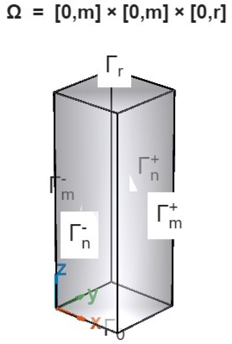
Figure 1. Geometry of the concrete specimen used for acoustic modeling. Ω = [ 0 , m ] × [ 0 , m ] × [ 0 , r ] is a concrete prism with a square cross-section and wave propagation along the z-axis. The boundary Γ = Γ 0 Γ r Γ m ± Γ n ± defines the six faces where different boundary conditions are applied.
Applsci 15 11378 g001
Figure 2. Visualization of acoustic wave propagation in a medium containing a rigid inclusion. The compact shape of the defect causes a clear reflection of the incident waves and a highly localized pressure distribution. The velocity inside the inclusion is nearly zero, indicating a restitutive behavior typical of rigid materials.
Applsci 15 11378 g002
Figure 3. Behavior of the acoustic field in the presence of a closed cavity. The incident waves are partially trapped, generating a symmetric and localized deformation of the wavefront. The pressure accumulates internally without significant dispersion.
Applsci 15 11378 g003
Figure 4. Pressure and velocity distribution near a healed microcrack. The disturbance introduced by the discontinuity is limited and does not generate significant variations in the velocity field.
Applsci 15 11378 g004
Figure 5. Dynamic effects of an open microcrack on the acoustic field. The defect introduces pronounced discontinuities in velocity and irregularities in wave propagation. A significant reduction in energy over time is observed, highlighting a dissipative behavior that weakens the stability of the system.
Applsci 15 11378 g005
Figure 6. Acoustic response of a medium affected by distributed and irregularly connected porosity. The pressure field appears fragmented, and the velocity exhibits complex fluctuations, with rapid and persistent energy decay. The defect structure amplifies wave dispersion within the material.
Applsci 15 11378 g006
Figure 7. Simulation in the presence of a large inclusion, comparable to the acoustic signal wavelength. The defect generates multiple reflection phenomena and internal resonance, significantly altering wave propagation and causing localized energetic instability.
Applsci 15 11378 g007
Figure 8. Time evolution of E ( t ) / E ( 0 ) for the six defect configurations listed in Table 2: rigid inclusion, closed cavity, healed microcrack, open microcrack, branching porosity, and macroscopic inclusion. E ( t ) is computed according to Equation (37) as the sum of kinetic and potential contributions over the computational domain and is normalized by the initial energy E ( 0 ) evaluated at the first time step immediately after source excitation.
Applsci 15 11378 g008
Table 1. Classification of defects according to the sign of the local coefficient μ i and their corresponding energetic and physical interpretation. The three representative categories analyzed in the simulations are summarized.
Defect TypeSign of μ i Energetic/Physical Behavior
Rigid inclusion or sealed crack μ i > 0 Stabilizing: It promotes local energy confinement and limits dissipation, enhancing coercivity.
Neutral or homogeneous region μ i 0 Neutral: Negligible influence on the global energy balance, corresponding to homogeneous propagation.
Open crack or porous cavity μ i < 0 Dissipative: It induces scattering, attenuation, and loss of coercivity through increased heterogeneity.
Table 2. Numerical configuration of the considered defects, reporting domain D i , local coefficient μ i , energetic classification, and observed physical behavior (C25/30 concrete, Gaussian excitation at 40 kHz, absorbing boundaries).
Defect TypeGeometry/Size μ i Energetic ClassificationObserved Physical Behavior
Rigid inclusionDisk, R = 0.05 m + 5 StabilizingStrong reflection of the wavefront, local pressure accumulation, and nearly zero internal velocity. Total energy remains almost constant over time.
Closed cavityDisk, R = 0.05 m + 5 StabilizingTemporary storage and elastic restitution of energy; slight and reversible attenuation in total energy.
Healed microcrackThin line 0 NeutralMinimal field disturbance; pressure and velocity nearly homogeneous; energy remains constant over time.
Open microcrackOpen thin line 5 DissipativeStrong velocity discontinuities and scattering; rapid energy decay due to leakage and attenuation.
Branching porosityFractal network 8 Highly dissipativeFragmented pressure field, complex velocity fluctuations, and pronounced and continuous energy loss.
Macroscopic inclusionDisk, R = 0.2 m 4 DestabilizingMultiple reflections and internal resonances; irregular drops in total energy and local energetic instability.
Table 3. Quantitative comparison among models: normalized energy decay after 200 μ s , maximum pressure amplitude, and phase delay.
ModelEnergy Decay (%)Max. Press. Ampl. (Pa)Phase Delay ( μ s)
[107]27.48.3 × 1043.1
[108]24.68.5 × 1042.9
Proposed approach (local coercivity)22.18.7 × 1042.8
Disclaimer/Publisher’s Note: The statements, opinions and data contained in all publications are solely those of the individual author(s) and contributor(s) and not of MDPI and/or the editor(s). MDPI and/or the editor(s) disclaim responsibility for any injury to people or property resulting from any ideas, methods, instructions or products referred to in the content.