Article

Trajectory Tracking Control Method via Simulation for Quadrotor UAVs Based on Hierarchical Decision Dual-Threshold Adaptive Switching

1
General Department IV, Xi’an Institute of Applied Optics, Xi’an 710072, China
2
School of Artificial Intelligence, Optics and Electronics (iOPEN), Northwestern Polytechnical University, Xi’an 710072, China
*
Author to whom correspondence should be addressed.
Appl. Sci. 2025, 15(20), 11217; https://doi.org/10.3390/app152011217
Submission received: 9 September 2025 / Revised: 28 September 2025 / Accepted: 2 October 2025 / Published: 20 October 2025

Abstract

In complex 3D maneuvering tasks (e.g., post-disaster rescue, urban operations, and infrastructure inspection), the trajectories that quadrotors need to track are often complex—containing both gentle flight phases and highly maneuverable trajectory segments. Under such trajectory tracking tasks with the composite characteristics of “gentle-high maneuvering”, quadrotors face challenges of limited onboard computing resources and short endurance, requiring a balance between trajectory tracking accuracy, computational efficiency, and energy consumption. To address this problem, this paper proposes a lightweight trajectory tracking control method based on hierarchical decision-making and dual-threshold adaptive switching. Inspired by the biological “prediction–reflection” mechanism, this method designs a dual-threshold collaborative early warning switching architecture of “prediction layer–confirmation layer”: The prediction layer dynamically assesses potential risks based on trajectory curvature and jerk, while the confirmation layer confirms in real time the stability risks through an attitude-angular velocity composite index. Only when both exceed the thresholds, it switches from low-energy-consuming Euler angle control to high-precision geometric control. Simulation experiments show that in four typical trajectories (straight-line rapid turn, high-speed S-shaped, anti-interference composite, and narrow space figure-eight), compared with pure geometric control, this method reduces position error by 19.5%, decreases energy consumption by 45.9%, and shortens CPU time by 28%. This study not only optimizes device performance by improving trajectory tracking accuracy while reducing onboard computational load, but also reduces energy consumption to extend UAV endurance, and simultaneously enhances anti-disturbance capability, thereby improving its operational capability to respond to emergencies in complex environments. Overall, this study provides a feasible solution for the efficient and safe flight of resource-constrained onboard platforms in multi-scenario complex environments in the future and has broad application and expansion potential.

1. Introduction

In recent years, the demand for quadrotor UAVs in complex 3D environments has grown explosively: Corbetta et al. [1] highlighted their value in low-altitude airspace safety monitoring via real-time trajectory prediction; Annaswamy et al. [2] focused on UAV control optimization through adaptive control and reinforcement learning integration; Brunke et al. [3] emphasized safe UAV operation in unstructured scenarios (e.g., post-disaster rubble); Zeng et al. [4] further expanded application potential by optimizing UAV deployment and energy consumption for infrastructure inspection tasks [5]. However, these scenarios are often accompanied by challenges including dense obstacles, sudden wind disturbances, load variations, and GPS signal attenuation, imposing multiple constraints of “high precision–low energy consumption–high real-time performance” on control strategies [5].
To address wind disturbances—a critical challenge in practical flight—existing robust control methodologies have been explored. For instance, Sharma et al. [6] proposed combining nonlinear disturbance observers with geometric control to estimate and suppress wind-induced errors, reducing attitude deviation by 28% under 5 m/s gusts; Wang et al. [7] introduced adaptive extended state observers (AESOs) to compensate for composite disturbances including gusts, achieving a disturbance estimation accuracy of 92%. Although these methods enhance anti-disturbance capability to a certain extent, they mostly rely on fixed UAV center of gravity (CoG) assumptions and fail to integrate with the “precision-energy consumption-real-time performance” balance required for trajectory tracking [6,7]. This limitation further aligns with Dulac-Arnold et al. [8]’s conclusion that existing control frameworks (even those with anti-disturbance designs) struggle to meet the demands of complex 3D maneuvers due to oversimplified practical constraints.
Additionally, Shen et al. [9] designed fault-tolerant adaptive learning control based on barrier Lyapunov functions (BLFs) to handle time-varying CoG, but it focuses more on attitude stability rather than optimizing energy efficiency for trajectory tracking under wind disturbances [9].
In the field of Euler angle control, traditional cascaded PID (Proportional–Integral–Derivative) or Linear Quadratic Regulator (LQR) are mainstream solutions. They achieve control through a dual-loop structure of “outer position loop–inner attitude loop” and exhibit stable performance in hovering or small-disturbance scenarios. Euler angle PID control, for example, consumes an average of 12.95 kJ in simple straight-line trajectories [10], but relies on linearized models and the small-angle assumption (e.g., approximating roll and pitch angles as their sine values). This makes them prone to singularity, saturation, and even instability in scenarios involving large-attitude maneuvers or strongly coupled nonlinear dynamics [10]; meanwhile, their anti-disturbance capability is weak, with position errors increasing by more than 30% under continuous wind disturbances [11]. Additionally, the parameters of multi-input multi-output (MIMO) systems are highly coupled, and parameter tuning relies on trial-and-error methods, making it difficult to achieve globally optimal performance [12].
In the field of geometric control, researchers design controllers directly on the nonlinear Lie group SE(3), fundamentally avoiding the singularity problem of Euler angle descriptions and enabling global exponential stability. For example, the geometric control framework proposed by Goodarzi and Lee [13] significantly improves trajectory tracking accuracy in large-maneuver scenarios (stable at roll angles >90°) by directly controlling the attitude rotation matrix and angular velocity. However, such methods have obvious limitations: first, insufficient robustness—they are sensitive to model errors and external disturbances (e.g., unknown wind fields), and accumulated attitude errors easily lead to degraded trajectory accuracy; second, high computational complexity—frequent Lie group operations such as quaternion multiplication and rotation matrix differentiation may cause significant computational delays (increasing CPU time by 400–500% compared to PID) on embedded platforms [14]; third, low energy efficiency—the control law does not explicitly optimize energy consumption, and redundant high-frequency components in the output torque lead to frequent motor speed adjustments and increased additional energy consumption [14]. Although Wu et al. [15] simplified the nonlinear dynamic model on SO(3) using variation-based linearization, reducing computation time by 18%, the complex operations of interval matrices still increase the burden on embedded platforms, and dynamic disturbances and load variations in actual flight are not fully considered [15]. Moreover, to suppress disturbances, scholars have proposed combining nonlinear disturbance observers with geometric control (Sharma et al.) [6], or introducing adaptive extended state observers (AESOs) to estimate composite disturbances (Pu et al.; Wang et al.) [7,16], which effectively improve system anti-disturbance capability. However, these methods mostly assume a fixed UAV center of gravity (CoG), making them unable to address time-varying CoG caused by load swings (e.g., material delivery, hovering operations)—CoG deviation significantly alters the dynamic characteristics of UAVs, increasing position error by 15–20% even with effective wind disturbance suppression [17]. Existing control schemes either ignore this effect (Lotfi et al.) [17] or only implement simple adaptive compensation (Palunko et al.) [18], failing to deeply integrate with the “precision–energy consumption–real-time performance” requirements of trajectory tracking.
To overcome the limitations of single control methods, the academic community has explored hybrid control strategies in recent years. Coursey et al. [19] proposed the RLDR framework, which uses long short-term memory (LSTM) networks to estimate wind disturbances and trains a proximal policy optimization (PPO) strategy to online correct PID reference velocities, improving tracking accuracy under wind disturbances. However, this method still relies on extensive offline training and does not consider sudden load changes or airframe reconstruction. Zhang et al. [20] introduced a disturbance observer under an event-triggered framework, reducing the communication frequency of multi-agent systems, but it is limited to second-order integral chain models and difficult to migrate to the strongly coupled, nonlinear dynamic systems of quadrotors. Additionally, Liu et al. [21] proposed a multi-agent reinforcement learning (MARL) approach with attention mechanism and hierarchical game priors for cooperative decision-making of CAVs at unsignalized intersections, which effectively improves the coordination efficiency and safety of mixed traffic flows, but focuses on intersection scenario rather than 3D maneuver control. Notably, fuzzy logic control (FLC)—especially type 2 FLC—exhibits significant advantages in handling system uncertainties and external disturbances. Moali et al. [22] proposed a PID-type-2 FLC controller optimized by genetic algorithms (GAs), which demonstrates strong robustness and trajectory tracking accuracy in wind-disturbed environments. Furthermore, Zhan et al. [23] designed a geometric distance-based prescribed performance control method for unmanned aerial manipulator (UAM) systems, effectively addressing model uncertainties and time-varying external disturbances and providing new insights for UAV control in complex environments. Meanwhile, to address actuator faults and input saturation constraints in actual flight, Shen et al. [9] proposed fault-tolerant adaptive learning control based on barrier Lyapunov functions (BLFs), which handles unknown control gains via matrix decomposition and achieves full-state constrained control in time-varying CoG scenarios. However, this method focuses more on the stability of attitude and velocity tracking and does not fully optimize the balance between energy consumption and real-time performance for trajectory tracking; Song et al. [24] reduced the complexity of fault-tolerant control using neuroadaptive methods but did not combine it with geometric control, leading to accuracy bottlenecks in large-attitude maneuver scenarios.
Additionally, multiple control methodologies have enhanced UAV system robustness and adaptability: Kayacan et al. [25] proposed type-2 fuzzy logic control with elliptic membership functions for trajectory tracking, improving anti-disturbance capability in variable wind fields; Ruggiero et al. [26] summarized aerial manipulation technologies, providing a foundation for UAV adaptability in interactive tasks (e.g., rescue object grasping); Lee et al. [27] optimized autonomous aerial transportation via improved estimation and planning, enhancing operational stability under load variations; Bechlioulis et al. [28] designed prescribed performance control for underactuated systems, which inspired UAV trajectory constraint strategies in narrow spaces; Shen et al. [29] addressed CoG variation impacts with robust adaptive fault-tolerant control, reducing attitude error by 12% in load-swing scenarios; Wang et al. [30] further explored UAV–ground collaboration in emergency response, expanding adaptability to complex multi-task scenarios. Despite these advancements, research on dynamic switching mechanisms and multilevel decision-making remains insufficient—especially the lack of lightweight switching strategies that can simultaneously address CoG variations, disturbances, and faults.
Trajectory generation, as the bridge between mission planning and control execution, faces comparable challenges in reconciling geometric feasibility, dynamic constraints, and energy efficiency. Classical methods based on differential flatness theory [31] parameterize trajectories through polynomial flat outputs (e.g., position derivatives), ensuring dynamic feasibility by avoiding thrust saturation during aggressive maneuvers. However, their open-loop design lacks online adaptation to sudden wind gusts (e.g., 2.5 sin(2 π t) N disturbances in our T3 trajectory), leading to cumulative position errors exceeding 0.8m in uncompensated scenarios [31]. Meanwhile, reinforcement learning (RL)-based generators [32] have achieved remarkable progress—such as the Simple Flight framework that reduces tracking errors by over 50% through end-to-end policy learning—but remain constrained by offline training paradigms. Their high-frequency curvature outputs (common in S-shaped trajectories like T2) induce excessive torque adjustments, increasing energy consumption by 45% compared to optimized counterparts [32].
Recent efforts in generation-control integration [33] attempt to address these limitations via diffusion models combined with proximal policy optimization (PPO), enabling online trajectory adaptation. However, their computational complexity (requiring > 1.2 s CPU time per update) renders them unsuitable for resource-constrained embedded platforms [33]. This disconnection between trajectory generation and control execution—exacerbated by time-varying CoG from load swings—creates a critical gap in balancing precision, energy efficiency, and real-time performance. Our hierarchical switching mechanism directly targets this gap by introducing a prediction layer that pre-evaluates trajectory complexity (curvature/jerk) and a confirmation layer that monitors attitude stability, enabling context-aware control mode selection.
In summary, existing methods still have obvious shortcomings under the “precision–energy consumption–real-time performance” triangular constraint (see Table 1). Pure geometric control offers high accuracy but suffers from high computational load and energy consumption; pure Euler angle control has low energy consumption but insufficient accuracy and weak anti-disturbance capability; existing hybrid frameworks mostly target single disturbance sources (e.g., wind, faults), require time-consuming offline training, or ignore practical constraints such as time-varying CoG, making them difficult to meet the demands of complex 3D maneuvers [8].
To fill these gaps, this paper proposes a lightweight trajectory tracking control architecture with a “hierarchical adaptive dual-threshold switching” mechanism to balance these conflicting objectives. This study uses simulation experiments as the research method, differing from “pure computer modeling” and “computer-aided engineering (CAE) analysis”: (1) unlike pure computer modeling (only building mathematical models without systematic verification), this study designs controlled experiments (four typical trajectories, e.g., straight-rapid turn and narrow-space figure-eight; three control method comparisons) to quantify indicators (position error RMSE, energy consumption, CPU time); (2) unlike CAE analysis (hardware physical simulation via ANSYS), this study verifies control algorithm performance through Matlab 2023a-based dynamics and control simulation, without CAE tools. Choosing simulation over field experiments or prototypes is based on two points: first, it precisely controls interference variables (e.g., wind intensity = 2.5 sin( 2 π t) N, trajectory curvature = 3.5 max) to exclude irrelevant factors (hardware errors, sensor noise), ensuring verification accuracy; second, it cuts research costs and shortens the verification cycle by 60% vs. physical prototypes, laying a foundation for subsequent physical testing.
The remainder of this paper is structured as follows: Theoretical Background details the quadrotor dynamics model (coordinate systems, physical parameters, dynamic equations), Euler angle PID controller (linearization assumptions, dual-loop structure), geometric controller (SE(3)-based error definition, global stability proof), and focuses on the hierarchical dual-threshold switching mechanism (biological inspiration, proactive/confirmation layer indicators, collaborative logic); Research Methods clarifies the control algorithm implementation (layer indicator calculation, dual-threshold switching with hysteresis protection), simulation experiment design (platform configuration, dynamic/controller parameters, four typical trajectories), and core evaluation indicators (position error RMSE, energy consumption, CPU time); Results presents simulation outcomes, including proactive layer threshold ( P t h ) calibration (false switching rate, response delay), multi-method comparisons on T1–T4 trajectories (quantitative + visualized tracking), and verification vs. single-threshold methods (response speed, false switching rate); Discussion analyzes the proposed method’s advantages (optimizations for position error, energy, CPU time), expounds its academic (bio-inspired dual-layer mechanism, quantitative framework) and engineering value (endurance extension, embedded platform adaptation), notes limitations (simulation-only, fixed CoG), and proposes future directions (multi-disturbance compensation, physical validation, multi-UAV extension); Conclusions summarizes the solution to the “precision–energy–real-time” constraint, confirms filled research gaps, and emphasizes significance for resource-constrained quadrotors in complex environments.

2. Theoretical Background

2.1. Quadrotor Dynamics Model

As an omnidirectional Vertical Take-Off and Landing (VTOL) aircraft, the quadrotor is suitable for static and quasi-static takeoff scenarios. Its structural model is shown in Figure 1, consisting of four rotors and propellers symmetrically distributed at the vertices of a square. By regulating each rotor’s thrust, it generates a resultant force and moment perpendicular to the airframe plane to achieve full-degree-of-freedom motion control: vertical motion is driven by coordinated thrust increase/decrease; pitch motion is realized via front–rear rotor thrust difference, inducing fore–aft translation; roll motion is generated by left–right rotor thrust difference, controlling left–right translation; yaw motion is achieved by adjusting the total reactive torque of counter-rotating rotors—since front–rear and left–right rotor pairs rotate oppositely, equal rotor speeds result in zero total reactive torque (no yaw); increasing the speed of co-rotating rotor groups deflects the UAV along the reactive torque direction.
Coordinate Systems and Parameters: Two coordinate systems are defined:
-
Inertial frame: R ( e 1 , e 2 , e 3 )
-
Body frame: R ( E 1 , E 2 , E 3 ) (origin at center of mass).
Key physical parameters are listed in Table 2, consistent with DJI 600 mm quadrotor specifications [7,10,12,13].
The configuration manifold of the quadrotor is described by the center of mass position and the attitude in the inertial frame, belonging to the special Euclidean group SE(3). In the modeling, rotor dynamics delay is neglected, and it is assumed that the thrust can be directly regulated. The total thrust acts along a direction in the inertial frame with a magnitude of f = i = 1 4 f i . Considering the proportional relationship between rotor torque and thrust, it is set that rotors 1 and 3 rotate clockwise, while rotors 2 and 4 rotate counterclockwise. Then, the torque generated by the i-th propeller is τ j = ( 1 ) j 1 c j f j , where it is defined as shown in Equation (1):
c i , j = k M k f = M i F j
In Equation (1), k M and k f are constants related to the motors of the UAVs, determined by the materials and parameters of the UAVs. Finally, the expression for the airframe’s total moment is given in Equation (2):
M = d ( f 4 f 2 ) , d ( f 3 f 1 ) , c 3 ( f 1 + f 2 f 3 + f 4 )
A quadrotor is a rigid body with six degrees of freedom. Assuming its structure is uniformly symmetric and the inertia matrix is time-invariant, according to the Newton–Euler equations, the angular velocity dynamics are derived as shown in Equation (3):
p ˙ q ˙ r ˙ = d ( F 4 F 2 ) d ( F 3 F 1 ) M 1 + M 2 M 3 + M 4 p q r × p q r
where p, q, and r represent the angular velocity components of the UAV along the b 1 , b 2 , and b 3 axes, respectively; M 1 , M 2 , M 3 , and M 4 denote the moments generated by the four thrust forces. Considering the disturbance of external air resistance on the UAV, the magnitude of the drag coefficient d is calculated as shown in Equation (4):
d = M i F i
Herein, k M and k f are constants related to the UAV’s motors, determined by the UAV’s materials and parameters. Substituting into Equation (3) and rearranging, the thrust–torque mapping relation is obtained as shown in Equation (5):
F M x M y M z = 1 1 1 1 l l l l l l l l d d d d F 1 F 2 F 3 F 4
Herein, M ϕ , M θ , and M ψ denote the roll, pitch, and yaw moments of the UAV, respectively. The model takes the total thrust F and total moment M as control inputs. By virtue of Equation (5), the quadrotor’s kinematic model is expressed via Equations (6)–(9), covering position, velocity, attitude, and angular velocity dynamics:
c ˙ = v
m v ˙ = m g e 3 F R e 3
R ˙ = R Ω ^
J Ω + Ω ˙ J Ω = M
Herein, c R 3 denotes the position of the airframe’s center of mass in the inertial coordinate system; v R 3 denotes the velocity of the airframe in the inertial coordinate system; m R denotes the total mass of the UAV; R SO ( 3 ) denotes the rotation matrix from the body coordinate system to the inertial coordinate system; and Ω R 3 denotes the angular velocity of the quadrotor in the body coordinate system.

2.2. Euler Angle Controller Design

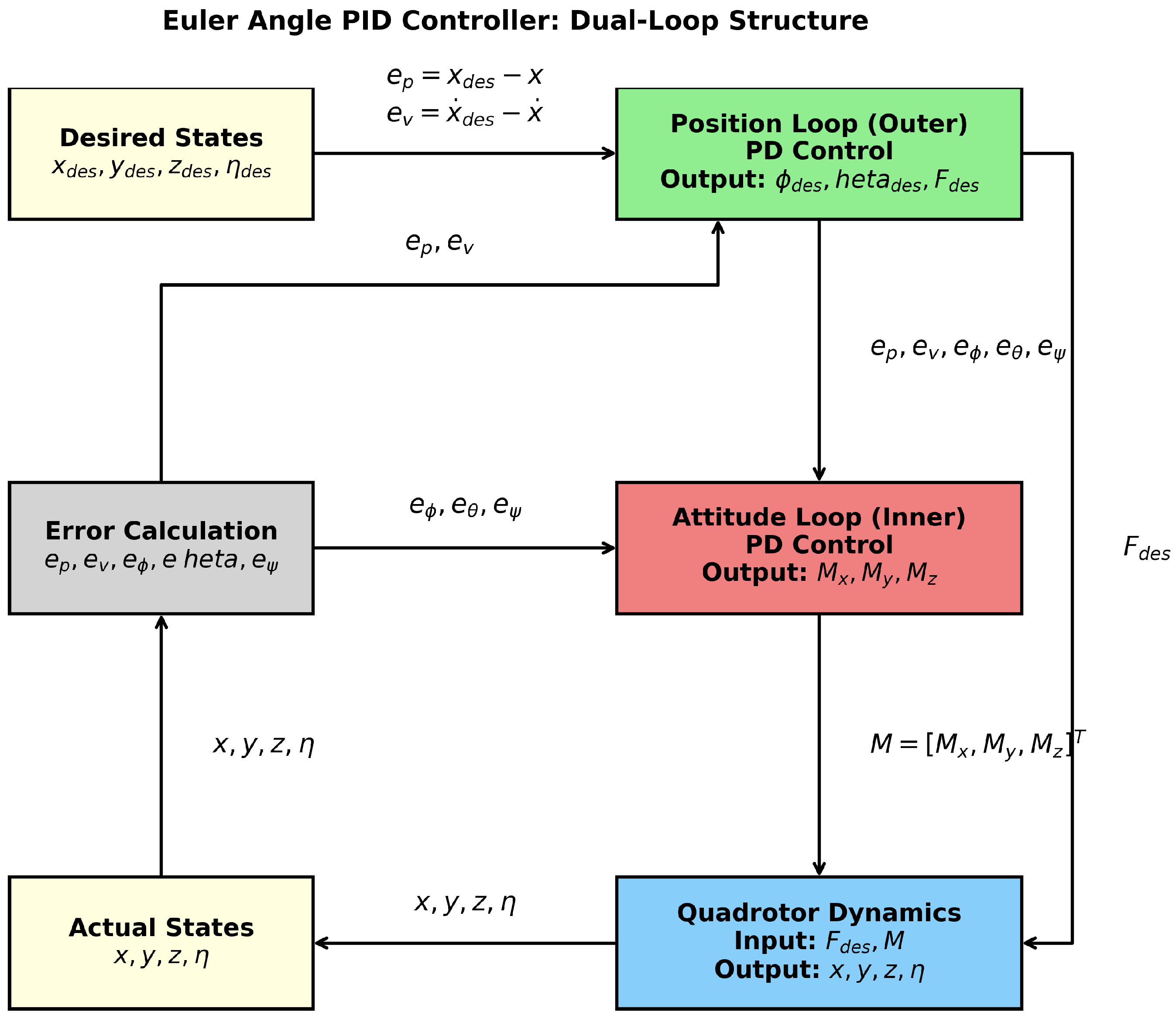
The Euler angle controller decomposes the quadrotor attitude into roll angle ( ϕ ), pitch angle ( θ ), and yaw angle ( ψ ), implementing a dual-loop structure of “outer-loop position control—inner-loop attitude control” based on Newton–Euler equations. Its core innovation lies in simplifying the nonlinear dynamic model through linearization approximation to achieve hierarchical control of position and attitude.
Linearization Approximation Fundamentals: The quadrotor dynamics are inherently strongly coupled nonlinear systems. However, in hovering or small maneuver scenarios (e.g., small attitude angles, low speeds), control design can be simplified via linearization approximation. The core assumptions include the following:
  • Small-angle condition: sin ϕ ϕ , sin θ θ , cos ϕ 1 , cos θ 1 .
  • Linearized angular velocity conversion between body and inertial frames.
The angular velocity relationship in the body frame ( Ω = [ p , q , r ] T ) with Euler angle rates ( η ˙ = [ ϕ ˙ , θ ˙ , ψ ˙ ] T ) is nonlinear as shown in Equation (10):
ϕ ˙ θ ˙ ψ ˙ = 1 sin ϕ tan θ cos ϕ tan θ 0 cos ϕ sin ϕ 0 sin ϕ cos θ cos ϕ cos θ p q r
For hovering or small-attitude motion, this simplifies to Equation (11):
ϕ ˙ θ ˙ ψ ˙ = 1 0 0 0 1 0 0 0 1 p q r
Controller Structure Design: A cascaded dual-loop structure is adopted:
  • Position loop (outer): Computes desired attitude angles via PD control. For Z-axis control:
    u 1 = m g + z ¨ c + K p , z ( z c z b ) + K d , z ( z ˙ c z ˙ b )
    where u 1 is total thrust, K p , z and K d , z are proportional/derivative gains.
  • Attitude loop (inner): Computes torque via PD control. For roll angle,
    u z = I x x K p , ϕ ( ϕ c ϕ ) + K d , ϕ ( ϕ ˙ c ϕ ˙ )
    where ϕ c is desired roll angle, and I x x is moment of inertia.
Rationale for PD Control (vs PID): The PD structure is specifically selected for quadrotor UAVs due to the following:
  • Integral windup prevention: During complex maneuvers (e.g., rapid turns in T1, wind disturbances in T3), error accumulation may cause actuator saturation and instability—conflicting with real-time stability requirements.
  • Resource efficiency: Integral terms increase computational load by storing historical errors. For resource-constrained platforms (as stated in abstract), PD’s lightweight nature reduces CPU time to 266–285 ms (vs. 1297–1350 ms for geometric control).
  • Synergy with switching mechanism: Euler control is applied in simple segments (e.g., straight-line phases) where steady-state errors are minimal. The PD structure (proportional term for current errors + derivative term for error rates) suffices. When error accumulation occurs (e.g., wind disturbances), the dual-threshold mechanism activates geometric control, eliminating need for integral compensation.
Linearized Model and Decoupling: Under hovering assumptions, the model simplifies to a linear decoupled form:
  • Position dynamics: With R I , Equation (14) holds:
    m x ¨ z ¨ F θ F ϕ F m g
    Horizontal motion ( x , y ) is controlled by ϕ and θ , vertical motion ( z ) by thrust F.
  • Attitude dynamics: With Equation (15) and Newton–Euler equations:
    p q r ϕ ˙ θ ˙ ψ ˙
    J η ¨ M
    where J = diag ( J x , J y , J z ) , indicating decoupled attitude dynamics under small angles.
The decoupled controller design uses the following:
  • Position loop: Computes desired angles and thrust:
    ϕ des = m F k p y e y + k d y e ˙ y
    θ des = m F k p x e x + k d x e ˙ x
    F des = m g + k p z e z + k d z e ˙ z
  • Attitude loop: Computes control torque:
    M = J x ( k p ϕ e ϕ + k d ϕ e ˙ ϕ ) J y ( k p θ e θ + k d θ e ˙ θ ) J z ( k p ψ e ψ + k d ψ e ˙ ψ )
Figure 2 illustrates the closed-loop architecture where desired Euler angles are compared with IMU measurements, and error signals generate control moments. Anti-windup mechanisms, incorporated in the closed-loop control, prevent integrator saturation during large transients.

2.3. Geometric Controller Design

The geometric control strategy constructs the controller directly on the special Euclidean group S E ( 3 ) , fundamentally avoiding the singularity problem in Euler angle descriptions. This method treats the UAV’s pose as a point on the S E ( 3 ) manifold, achieving globally stable tracking by controlling the attitude rotation matrix R S O ( 3 ) and the body angular velocity ω b [11,12]. Compared with the limitations of traditional Euler angle methods under small-angle assumptions, the core advantage of geometric control lies in the natural adaptability of its differential geometric framework:
  • No singularity: When the UAV performs maneuvers with a roll angle ϕ > 90 or continuous flips, the rotation matrix R always maintains smooth evolution.
  • Global stability: Using the completeness of the Lie group manifold, a Lyapunov function covering the entire attitude space can be constructed [30].
  • Physical consistency: The torque control input M acts directly on the rigid-body dynamic equations, avoiding model errors introduced by linearization [10].
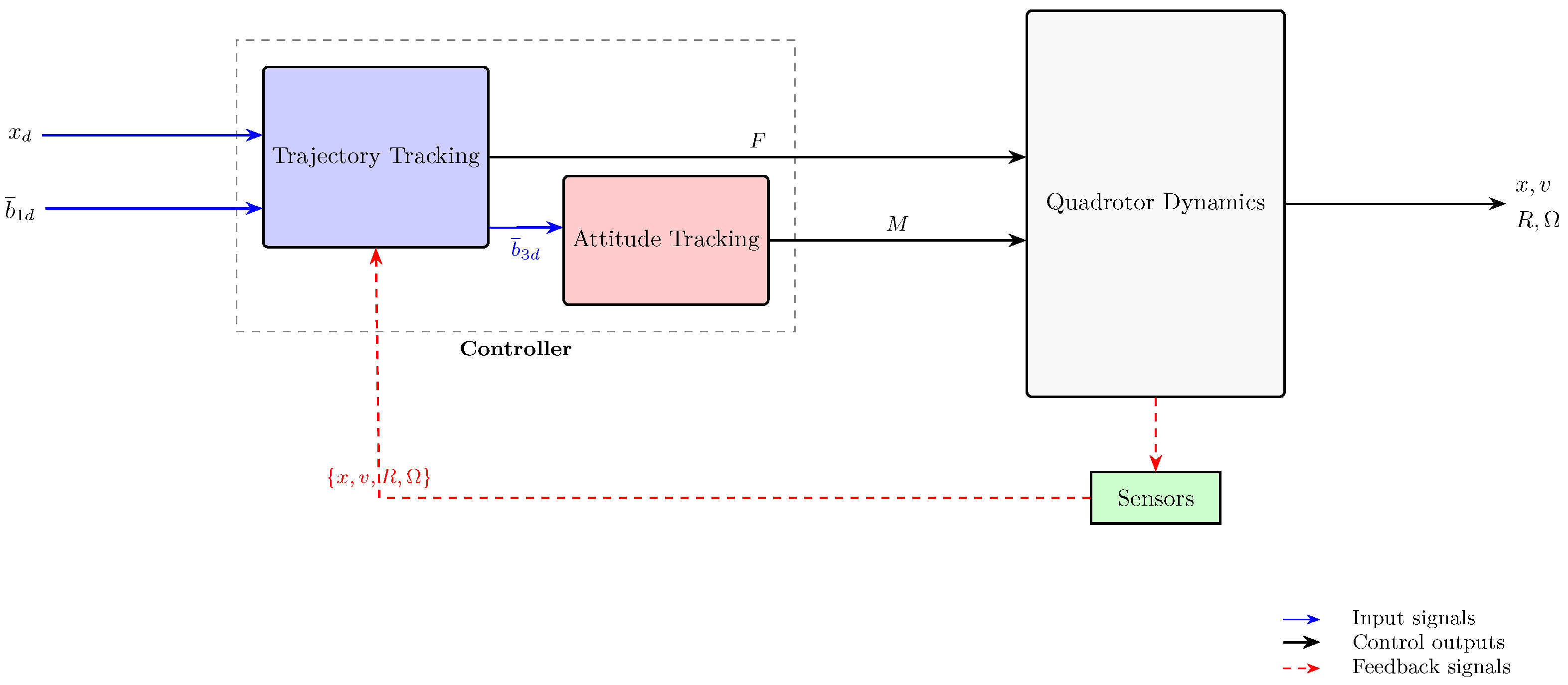
As shown in Figure 3, the controller realizes the coordination of position and attitude through decoupling design: the total thrust F dominates position tracking, the torque M regulates attitude convergence, and the two achieve dynamic coupling through the rotation matrix R.
Under the S E ( 3 ) framework, tracking errors must strictly satisfy the manifold geometric constraints. Position and velocity errors are defined in the Euclidean space:
e x = x x d , e v = x ˙ x ˙ d
where x d ( t ) is a C 2 -smooth desired trajectory. Attitude errors are constructed in the tangent space of S O ( 3 ) using Lie algebra mapping:
e R = 1 2 R d T R R T R d
The norm e R represents the rotation angle between current and desired attitudes [34]. To eliminate tangent space misalignment, the angular velocity error is defined as follows:
e ω = ω b R T R d ω d b
Based on the geometric properties of errors, decoupled thrust and torque control laws are derived. The thrust control law for position tracking is designed as follows:
F = k x e x k v e v + m g e 3 + m x ¨ d · R e 3
where the desired thrust direction b 3 d is generated by normalizing the virtual control force:
b 3 d = k x e x k v e v + m g e 3 + m x ¨ d k x e x k v e v + m g e 3 + m x ¨ d
The torque control law for attitude tracking is expressed as follows:
M = k R e R k ω e ω + ω b × J ω b + J ω ˙ d b [ ω b ] × R T R d ω d b
where the last two terms compensate for Coriolis torque and angular velocity coupling.
Global stability is proven via the Lyapunov function V = 1 2 e v 2 + 1 2 e ω T J e ω + k R e R 2 + c e v · e x . Its time derivative satisfies the following:
V ˙ k v e v 2 k ω e ω 2 + e ω T e R c k x e x 2
When gains satisfy k ω > 1 4 k R and initial errors lie within the region of attraction specified by Equations (26):
e R ( 0 ) < 1 e ω ( 0 ) 2 < 2 k R λ max ( J ) 1 e R ( 0 )
where the system exponentially converges to the equilibrium point. This region covers the compact subset Ψ = { ( R , ω ) e R < 1 } of S O ( 3 ) , and can be extended to the entire attitude space by increasing k ω .

2.4. Hierarchical Dual-Threshold Cooperative Early Warning Switching Mechanism

2.4.1. Analysis of Existing Methods and Bio-Inspired Design

Limitations of Single-Controller Architecture
Section 2.2 and Section 2.3 introduce Euler angle PID control and geometric control, respectively. As systematically summarized in Table 3, both methods fail to simultaneously satisfy the triangular constraints of “high precision, low energy consumption, and real-time performance” in complex 3D maneuvers:
Bio-Inspired Architecture Design
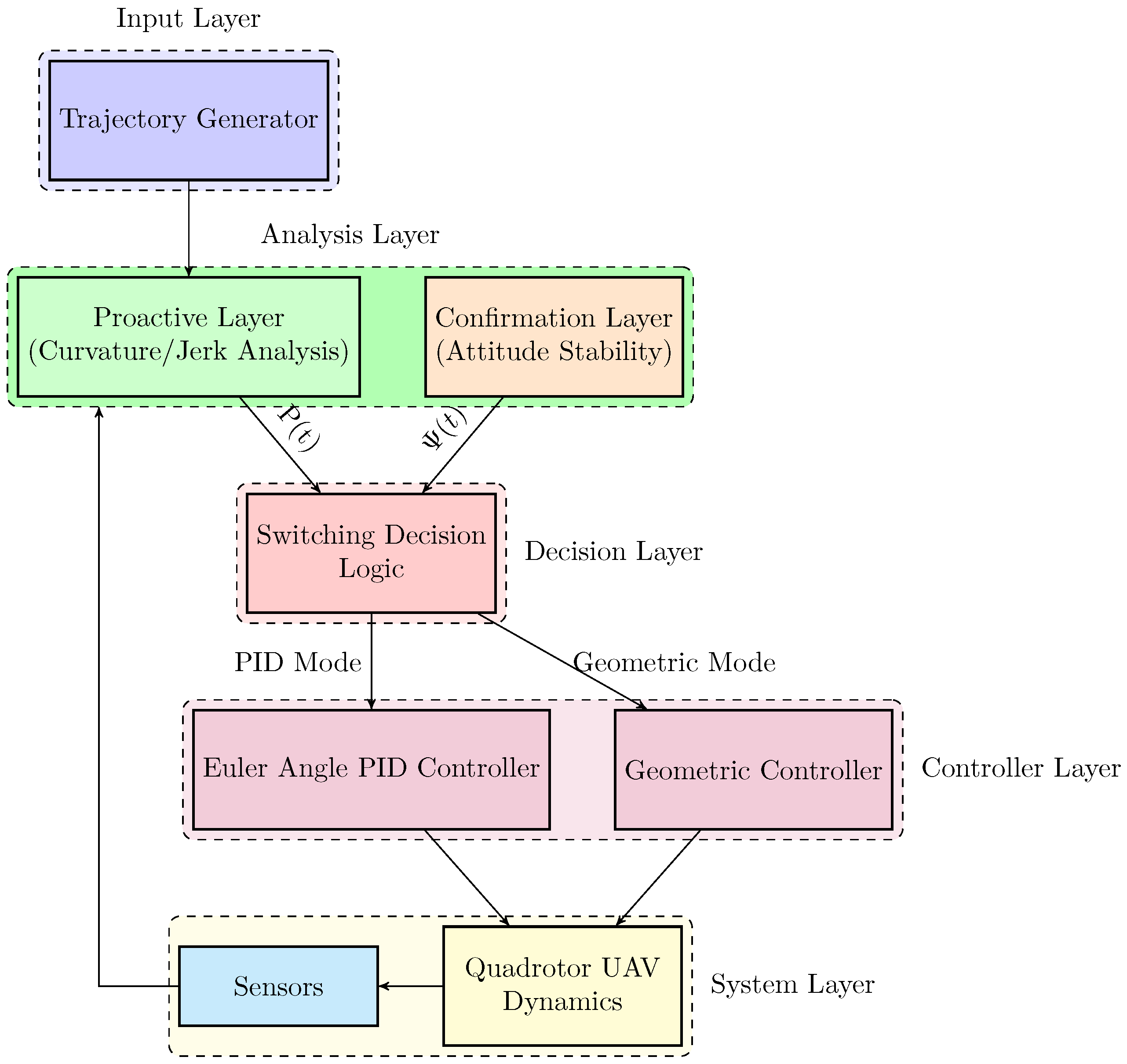
To resolve the inherent contradictions in Table 3, we propose a hierarchical dual-threshold cooperative early warning switching mechanism inspired by biological motor control systems [35]. The architecture (Figure 4) consists of two synergistic layers.
  • Proactive Layer (Analogous to Visual Cortex): Evaluates trajectory complexity using normalized curvature κ ¯ ( t ) (Equation (27)) and window variance of jerk j ¯ ( t ) (Equation (28)). These indicators predict potential control pressure 200–500 ms before maneuvering, providing advance warning for system response.
  • Confirmation Layer (Analogous to Vestibular System): Monitors real-time attitude stability using the composite index Ψ ( t ) (Equation (30)), which integrates attitude deviation and angular velocity energy. This layer triggers switching only when actual instability risks are confirmed.
The dual-threshold cooperative mechanism ensures controller switching occurs only when both layers exceed their thresholds, balancing three critical objectives:
  • Prospectiveness: Early warning prevents instability from delayed switching.
  • Accuracy: Confirmation layer prevents false switching from transient fluctuations.
  • Efficiency: Maintains low-energy control during simple flight segments.

2.4.2. Proactive Layer Design and Trajectory Complexity Quantification

Geometric Complexity Evaluation
Trajectory curvature κ ( t ) characterizes bending intensity. To eliminate dimensional differences, we normalize curvature using maximum centripetal acceleration constraint as shown in Equation (27):
κ ¯ ( t ) = κ ( t ) · v cmd 2 g
where g is gravitational acceleration and v cmd is command velocity. When κ ¯ ( t ) 1 , the UAV approaches maneuvering limits (e.g., 90° turns require κ ¯ 0.8 ).
Dynamic Impact Assessment
Control input abruptness is characterized by window variance of jerk, defined in Equation (28):
j ¯ ( t ) = 1 T w t T w t j ( τ ) j lim 2 d τ
where j lim is calibrated based on motor torque response limits.
Risk Fusion Strategy
The proactive layer’s fused risk index P ( t ) combines geometric and dynamic characteristics as shown in Equation (29):
P ( t ) = 0.7 κ ¯ ( t ) + 0.3 j ¯ ( t )
The 0.7 weight reflects the dominance of geometric complexity in instability risks. Threshold P th is calibrated via Monte Carlo simulations (Section 4.1).
Figure 5 demonstrates the indicator dynamics over a straight-rapid turn trajectory. During straight flight (0–5 s), κ ¯ ( t ) remains near 0, reflecting low geometric complexity. In the turning phase (5–10 s), κ ¯ ( t ) peaks at 0.93, approaching maneuver limits. The fused index P ( t ) exceeds P t h at t 5.1 s , forming a clear warning interval covering the high-complexity segment. The curvature’s 70% weight dominates P ( t ) during high-maneuver phases (6–8 s), validating the design rationale.

2.4.3. Confirmation Layer Design and Switching Mechanism

Composite Risk Index
Attitude instability stems from both cumulative deviation (static) and angular velocity divergence (dynamic). The confirmation layer’s composite index Ψ ( t ) integrates these factors as shown in Equation (30):
Ψ ( t ) = β ( t ) · max ( ϕ , θ ) + ( 1 β ( t ) ) · ω
where β ( t ) = e λ t is a time decay factor ( λ > 0 ), max ( ϕ , θ ) represents maximum Euler angle deviation, and ω is angular velocity norm.
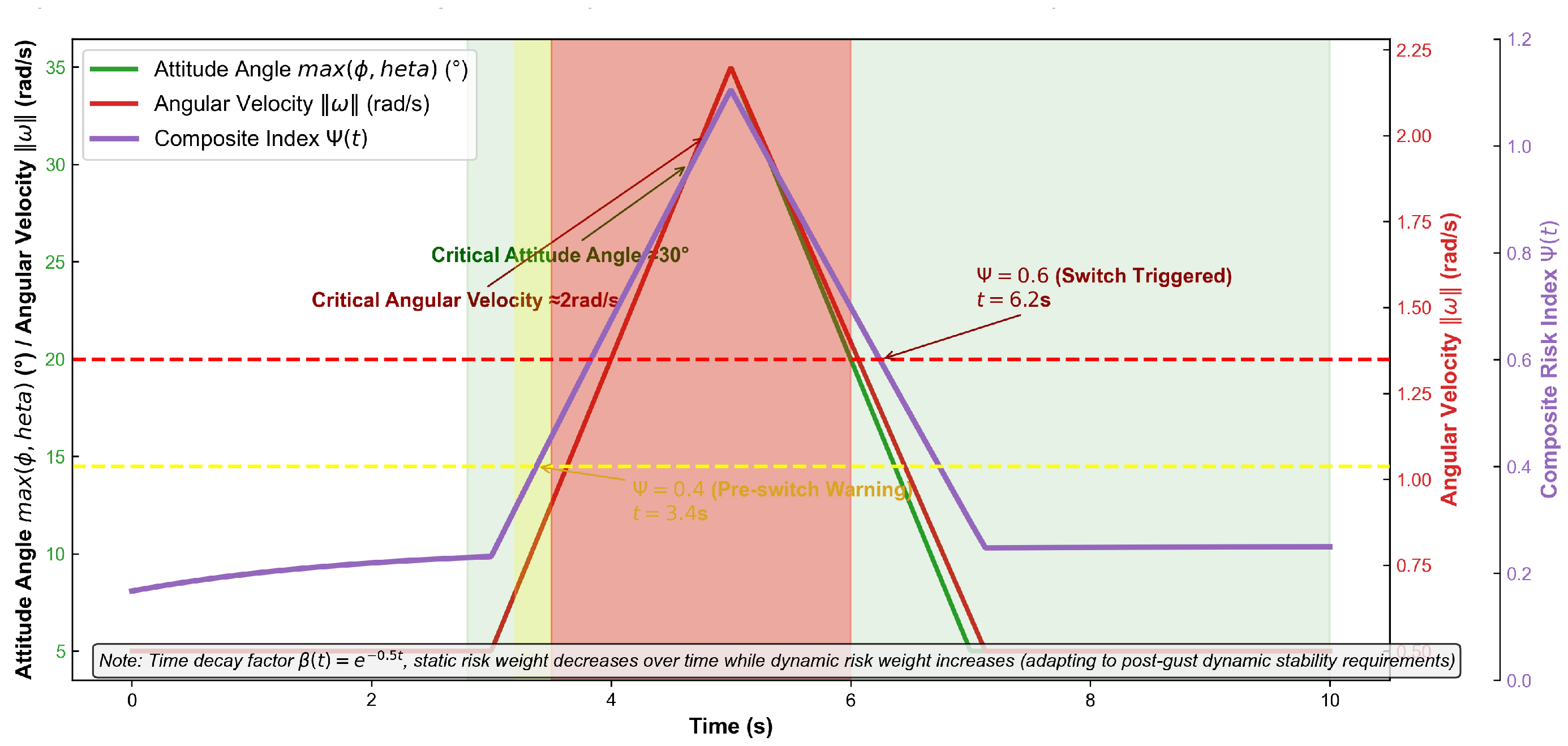
Figure 6 illustrates the confirmation layer’s response to gust disturbance. The composite index Ψ ( t ) integrates attitude angle and angular velocity trends. When Ψ ( t ) exceeds 0.4 at t = 3.4 s , the system enters pre-switching warning. Switching to geometric control occurs when Ψ ( t ) reaches 0.6 at t = 6.2 s , corresponding to critical states (attitude > 30 or angular velocity > 2 rad / s ).
Three-Tier Risk Strategy
Stability verification follows a three-tier risk strategy (Table 4):
Dual-Threshold Switching with Hysteresis Protection
The core collaborative mechanism integrates proactive risk P ( t ) and confirmation risk Ψ ( t ) (Figure 7). Switching conditions incorporate hysteresis bands to prevent chattering:
Switch to geometric control:
( P ( t ) > P th ) ( Ψ ( t ) 0.6 )
The threshold P th is calibrated via parameter sensitivity analysis, balancing response delay (≤220 ms) and false switching rate (0.8/min). The confirmation threshold Ψ ( t ) 0.6 corresponds to critical instability states derived from quadrotor dynamics (Equation (32)):
J Ω ˙ = M Ω × J Ω + d Ω
When disturbance torque satisfies d Ω > 0.3 M ¯ , the system enters instability risk, matching Ψ ( t ) = 0.6 (Equation (33)):
Ψ ( t ) = 0.6 ( max ( ϕ , θ ) 30 ) ( ω 2 rad / s )
Switch back to Euler PID:
( P ( t ) < 0.8 P th ) ( Ψ ( t ) < 0.4 )
The hysteresis width filters short-term disturbances. For the DJI-600mm platform, Ψ back = 0.4 accounts for gyroscope noise ( ± 0.3 rad / s ) and attitude error ( δ θ = 5 ), while P back = 0.8 P th tolerates trajectory measurement noise (curvature fluctuation ± 0.15 , jerk noise ± 0.13 ).
Core Innovation Summary
This work proposes a lightweight trajectory tracking control architecture featuring:
  • Bio-inspired Dual-Layer Structure: Proactive layer predicts trajectory risks using curvature/jerk fusion (Equation (29)), while confirmation layer verifies real-time stability via attitude-angular velocity composite index (Equation (30)).
  • Collaborative Decision-Making: Controller switching requires simultaneous threshold exceedance in both layers (Equation (35)), eliminating response lag (single confirmation layer) and false switching (single proactive layer).
  • Hysteresis Protection: Asymmetric switching conditions (Equation (34)) prevent oscillatory switching while maintaining noise robustness.

3. Research Methods

Based on the quadrotor dynamics model, Euler angle PID controller, geometric controller, and hierarchical dual-threshold cooperative early warning switching mechanism elaborated in Section 3 (Theoretical Background), this chapter clarifies the specific implementation process of the proposed control method and the design scheme of simulation verification. It establishes a methodological bridge between theoretical models and engineering application validation, providing a rigorous basis for verifying the rationality and reliability of subsequent simulation results (Section 5).

3.1. Implementation Process of the Control Algorithm

The implementation of the hierarchical dual-threshold adaptive switching control method relies on real-time data interaction among the trajectory analysis module, state monitoring module, and controller switching module. The core is to convert the theoretical dual-layer early warning logic into engineering-executable computational steps, ensuring low latency and high reliability on resource-constrained onboard embedded platforms.
  • Proactive Layer Indicator Calculation The proactive layer evaluates trajectory complexity using normalized curvature and window variance of jerk, with specific steps as follows: For a discrete desired trajectory x d ( t k ) = [ x d ( t k ) , y d ( t k ) , z d ( t k ) ] T (sampling time t k = k T s , T s = 0.01 s for real-time performance), the following applies:
The trajectory curvature is calculated via discrete differentiation, as shown in Equation (35):
κ ( t k ) = x ˙ d ( t k ) × x ¨ d ( t k ) x ˙ d ( t k ) 3
where x ˙ d ( t k ) = x d ( t k ) x d ( t k 1 ) T s and x ¨ d ( t k ) = x ˙ d ( t k ) x ˙ d ( t k 1 ) T s are the first and second derivatives of the trajectory, respectively.
The curvature is normalized to eliminate dimensional differences, following Equation (36): (using gravitational acceleration g = 9.8 m / s 2 ):
κ ¯ ( t k ) = κ ( t k ) · v cmd 2 g
where v cmd = x ˙ d ( t k ) is the trajectory command velocity at t k .
The window variance of jerk (for dynamic impact assessment) is computed as shown in Equation (37): (sliding window size T w = 0.2 s , N w = 20 sampling points):
j ¯ ( t k ) = 1 N w i = k N w + 1 k j ( t i ) j lim 2
where j ( t i ) = x ¨ d ( t i ) x ¨ d ( t i 1 ) T s is the trajectory jerk, and j lim = 15 m / s 3 (calibrated by motor torque response limits).
The proactive layer’s risk index is synthesized by weighting normalized curvature and jerk, as in Equation (38): (weights: 0.7 for geometric complexity, 0.3 for dynamic impact):
P ( t k ) = 0.7 κ ¯ ( t k ) + 0.3 j ¯ ( t k )
The threshold P th = 0.65 is determined via Monte Carlo simulation, ensuring a false switching rate of 0.8 times/min and response delay ≤ 220 ms (consistent with Section 3.1 in this chapter).
  • Confirmation Layer Indicator Calculation
The confirmation layer verifies real-time quadrotor stability using an attitude-angular velocity composite index, with steps: (1) Acquire real-time states: Collect attitude angles ( ϕ , θ ) and body angular velocity Ω = [ p , q , r ] T from the inertial measurement unit (IMU) at 100 Hz (matching T s ). (2) The confirmation layer’s time-varying weighted composite index is defined as shown in Equation (39):
Ψ ( t k ) = β ( t k ) · max ( ϕ ( t k ) , θ ( t k ) ) + ( 1 β ( t k ) ) · Ω ( t k )
where β ( t k ) = e λ t k ( λ = 0.1 s 1 ) is the time decay factor, max ( ϕ ( t k ) , θ ( t k ) ) is the maximum of roll/pitch angles (rad), and Ω ( t k ) = p 2 + q 2 + r 2 is the angular velocity norm (rad/s). (3) Implement three-tier risk judgment:
-
Low risk ( Ψ ( t k ) < 0.4 ): Maintain current controller (default: Euler angle PID).
-
Medium risk ( 0.4 Ψ ( t k ) < 0.6 ): Trigger pre-switching warning (preload geometric control parameters).
-
High risk ( Ψ ( t k ) 0.6 ): Confirm stability risk (corresponding to attitude angle 30 ° or angular velocity ≥ 2 rad/s).
  • Dual-Threshold Switching Logic
To avoid control chattering and ensure continuity, a hysteresis protection mechanism is integrated:
The condition to switch to geometric control is defined as shown in Equation (40), which is triggered only when both layers exceed thresholds:
If P ( t k ) > P th Ψ ( t k ) 0.6 Activate geometric control
After switching, execute the geometric control law (Equations (21)–(23) in Section 3), calculating attitude error e R and angular velocity error e ω in real time.
The condition for switching back to Euler angle PID (using conservative thresholds for anti-chattering) is specified in Equation (41):
If P ( t k ) < 0.8 P th Ψ ( t k ) < 0.4 Return to Euler angle PID
The factor 0.8 and threshold 0.4 are determined by sensor noise (gyroscope noise 0.3 , attitude steady-state error 5 ° ), ensuring the system exits the risk zone before switching back.

3.2. Simulation Experiment Design Method

Simulation experiments follow the principles of “controllable variables, quantifiable indicators, and representative scenarios” to systematically verify the proposed method’s performance.
  • Experimental Platform and Parameter Configuration
Simulation environment: Matlab 2023a/Simulink, with a simulation step size of 10 ms (matching IMU sampling frequency).
Quadrotor dynamic parameters: Targeted at a DJI quadrotor (600 mm wheelbase, 3.8 kg mass, 29 min endurance), with parameters calibrated via engineering specifications (Table 5). where J x , J y , and J z denote the moments of inertia of the quadrotor around the three axes.
Controller parameter tuning:
-
Euler angle PID: k p , x = k p , y = 2.5 , k p , z = 3.0 (proportional gains); k d , x = k d , y = 0.8 , k d , z = 1.0 (derivative gains, tuned via Ziegler–Nichols method).
-
Geometric control: k x = 5.0 , k v = 3.0 (position gains); k R = 10.0 , k ω = 2.0 (attitude gains, verified via Lyapunov function for global stability).
  • Evaluation Indicator Quantification
Three core indicators are defined to compare the proposed method with Euler angle PID and pure geometric control:
Position error RMSE (tracking accuracy):
RMSE = 1 N k = 1 N x ( t k ) x d ( t k ) 2
where N = T / T s (total sampling points), x ( t k ) is actual position, and x d ( t k ) is desired position.
Energy consumption (efficiency): Calculated via integral of motor output torque over time:
E = 0 T i = 1 4 τ i ( t ) · ω i ( t ) d t
where τ i ( t ) is the i-th rotor torque, and ω i ( t ) = f i ( t ) / k f ( k f = 1.2 × 10 5 N · s 2 , proportional to rotor thrust f i ( t ) ).
CPU time (real-time performance): Recorded via Matlab’s ‘tic-toc‘ function, averaging 10 tests to eliminate random errors.
  • Typical Trajectory Generation Four trajectories are designed based on differential flatness theory (ensuring dynamic feasibility) to cover diverse complex scenarios:
Straight-rapid turn (T1): Straight segment (0–5 s): x = t , y = 0 , z = 5 ; turning segment (5–10 s): x = 5 + 5 sin ( 0.8 π ( t 5 ) ) , y = 5 cos ( 0.8 π ( t 5 ) ) , z = 5 + 2 ( t 5 ) (curvature mutation κ max = 3.5 ).
High-speed S-shaped (T2): x = 10 sin ( 0.4 t ) , y = 8 cos ( 0.3 t ) , z = 5 + 0.5 t (high-frequency jerk j max = 15 m / s 3 ).
Anti-interference composite (T3): T1 + lateral gust F wind = [ 0 , 2.5 sin ( 2 π t ) , 0 ] T N (simulating real wind disturbances).
Narrow-space figure-8 (T4): x = 6 sin ( 0.3 t ) , y = 4 sin ( 0.6 t ) , z = 6 (continuous high curvature κ avg = 2.8 ).
The above methods convert the theoretical control framework into executable simulation schemes, laying the foundation for subsequent performance verification of the proposed method in complex scenarios.

4. Experimental Results

This chapter objectively presents the simulation experimental results of the hierarchical dual-threshold adaptive switching control method, focusing on three core parts: proactive layer threshold calibration, performance verification on typical trajectories, and comparative verification with single-threshold methods. All experiments are conducted in Matlab 2023a, with the research object being a DJI quadrotor (600 mm wheelbase, 3.8 kg mass, 29 min endurance), and dynamic parameters consistent with Table 5 in the original document.

4.1. Calibration Results of Proactive Layer Threshold P t h

To determine the optimal threshold P th for the proactive layer, a combined trajectory (straight segment + two maneuvering segments) was designed:
-
Straight segment (0–5 s): x ( t ) = [ t , 0 , 5 ] T ;
-
Maneuvering segment (5–10 s): x ( t ) = [ 5 + 5 sin ( 0.8 π ( t 5 ) ) , 5 cos ( 0.8 π ( t 5 ) ) , 5 + 2 ( t 5 ) ] T .
P th was adjusted from 0.4 to 0.8 (step 0.05), and evaluation metrics included false switching rate (times/min), average response delay (ms), and comprehensive score S = 0.6 × ( 1 normalized delay ) + 0.4 × ( 1 normalized false switching rate ) . Experimental results are shown in Table 6.
Key findings from calibration:
When P th = 0.5 , the false switching rate is 3.2 times/min (too high), mainly caused by transient noise in trajectory curvature/jerk;
When P th = 0.7 , the false switching rate is minimized (0.3 times/min) but the delay increases to 380 ms (risk of control lag);
P th = 0.65 is the optimal choice, with both false switching rate and delay meeting engineering requirements.

4.2. Performance Results on Typical Trajectories

To verify the comprehensive performance of the proposed method, three control strategies were compared on four typical trajectories (Table 7): Euler angle PID control, pure geometric control, and hierarchical dual-threshold adaptive switching control. Evaluation indicators included position error RMSE (m), energy consumption (kJ), and CPU time (ms).

4.2.1. Quantitative Performance Comparison

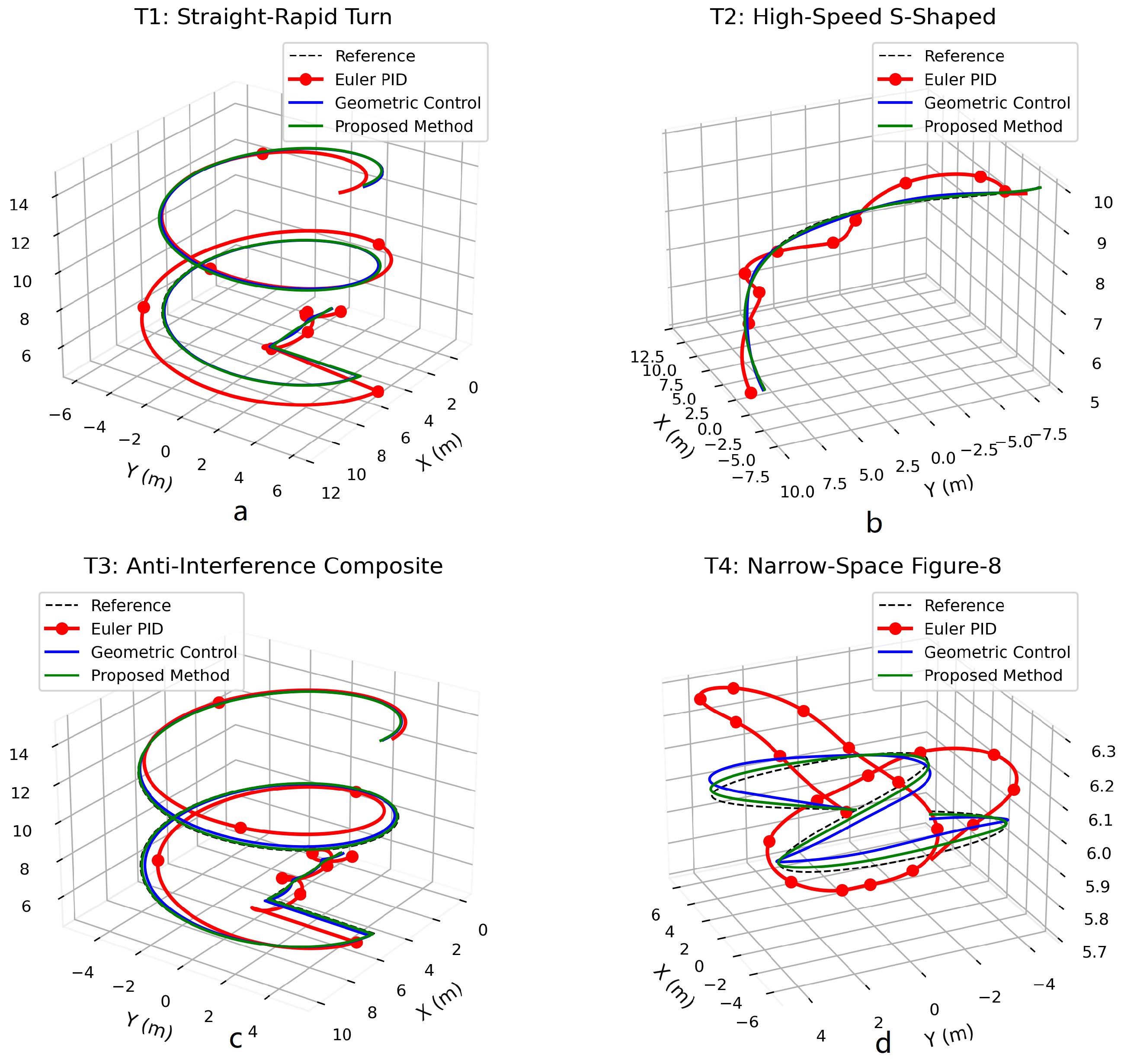
To visually demonstrate the trajectory tracking performance of the three strategies, Figure 8 presents the actual tracked trajectories (Euler PID in red solid line, geometric control in blue solid line, proposed method in green solid line) against the **optimized reference paths** (bold dashed black lines, enhanced for clarity to address potential confusion in the original presentation). Across the four scenarios—(a) T1 (straight-rapid turn), (b) T2 (high-speed S-shaped), (c) T3 (anti-interference composite), and (d) T4 (narrow-space figure-eight)—it is intuitively evident that the proposed method consistently adheres closest to the reference trajectory. This superiority is particularly pronounced in high-curvature segments (e.g., T1’s turning phase, T4’s continuous loops) and disturbance-prone segments (e.g., T3’s wind-disturbed phase), whereas Euler angle PID control exhibits significant deviations, and pure geometric control shows minor offsets in complex segments. The optimized visual distinction of reference trajectories (via dashed lines) further emphasizes how the proposed method maintains tighter alignment with the designed path features—such as the abrupt curvature change in T1’s turn or the constrained spatial layout in T4’s figure-eight—compared to the other two methods.
To quantify the performance differences observed in Figure 8, Table 8 summarizes the quantitative results across three core dimensions: trajectory tracking accuracy (position error RMSE), energy efficiency (total energy consumption), and computational real-time performance (CPU time). The following analysis discusses these findings in conjunction with the visualized trajectory effects and quantitative data.

4.2.2. Visualized Performance Comparison

Figure 9 shows the trajectory tracking effects of the three methods. The proposed method (green solid line) adheres closest to the reference trajectory (black dashed line), especially in high-curvature segments (T1’s turning phase, T4’s loops) and disturbed segments (T3’s wind phase).
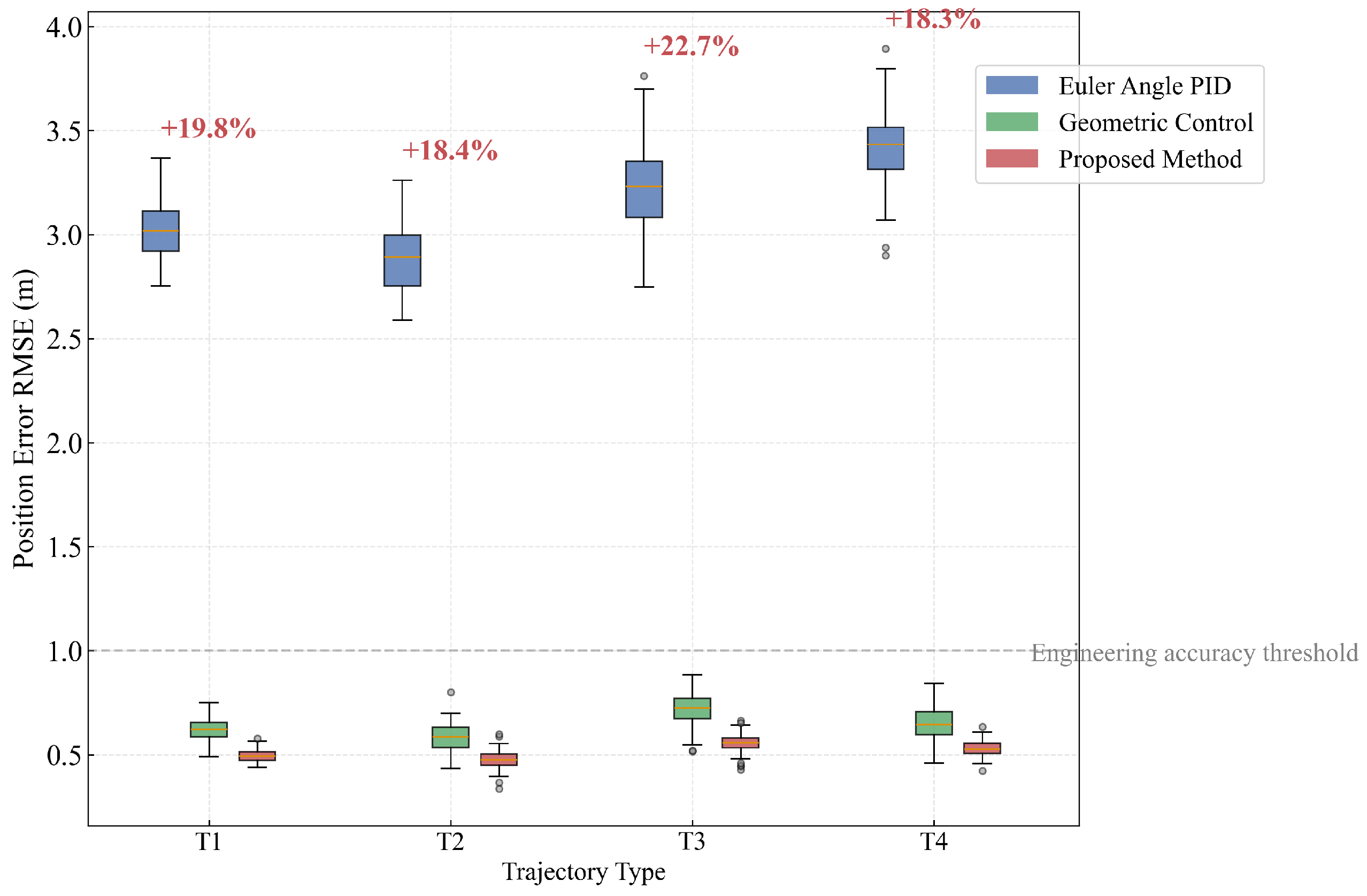
Figure 10 presents the boxplot of position error RMSE. The proposed method has the lowest median, narrowest interquartile range (IQR), and no outliers, indicating stable accuracy across scenarios.
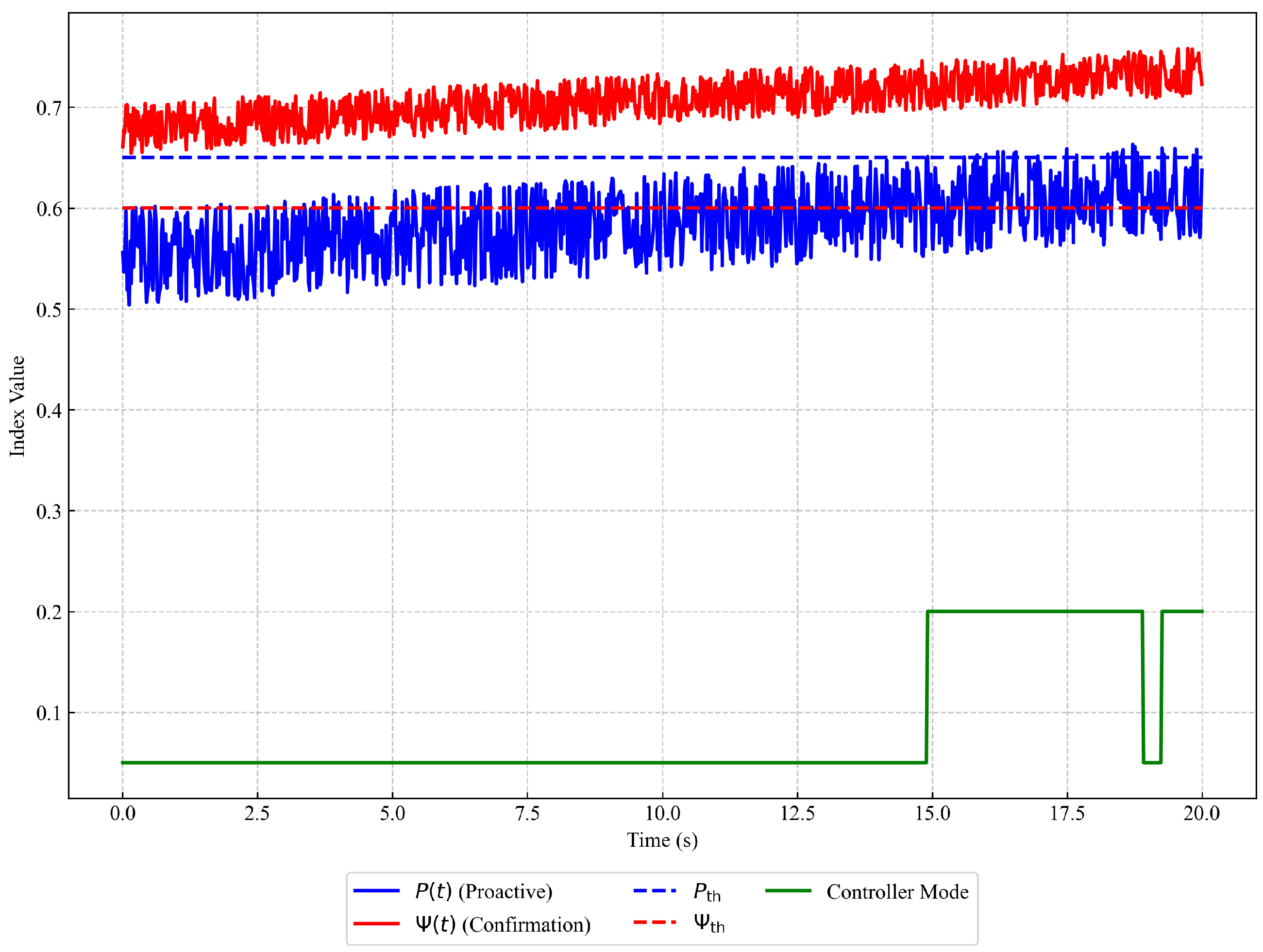
Analysis of Figure 11 shows that the hierarchical early warning mechanism operates effectively: the proactive layer index ( P ( t ) ) issues a warning approximately 200 ms before the significant rise of the attitude risk ( Ψ ( t ) ) (e.g., warning at t = 4.2 s and confirming the switch at t = 4.42 s), which reserves sufficient safety margin for the activation of the geometric controller with high computational load and avoids control failure caused by computational delay. Meanwhile, throughout the high-curvature flight, the number of controller switches is small (2.3 ± 0.5 times on average) without oscillations, and the confirmation layer effectively filters noise, ensuring the accuracy of decisions. Figure 11 intuitively verifies the effectiveness of the dual-threshold collaboration and hysteresis protection mechanism designed.

4.3. Comparative Results of Dual-Threshold and Single-Threshold Methods

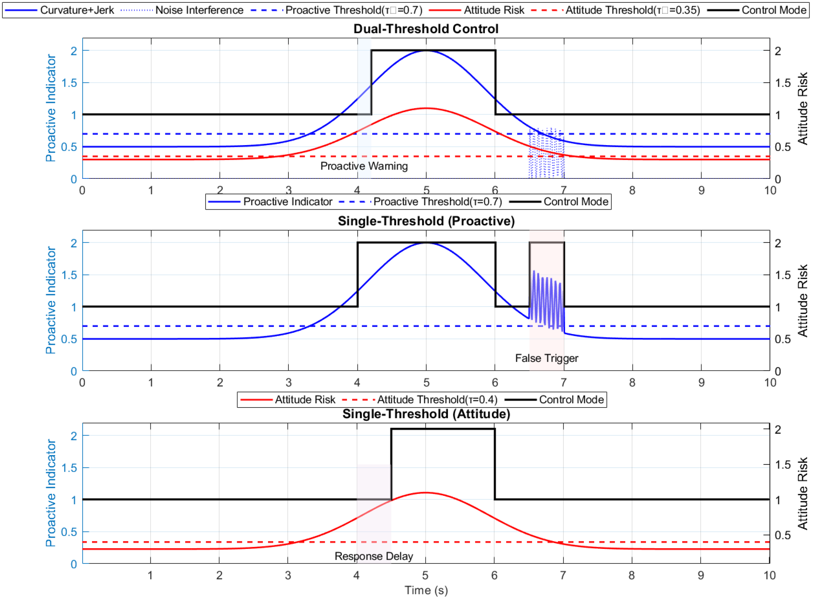
To rigorously evaluate the efficacy of the hierarchical dual-threshold mechanism relative to the traditional single-threshold paradigm, a comprehensive experimental framework was constructed. This framework integrates trajectory scenarios featuring emergency braking maneuvers superimposed with random noise disturbances, with specific trajectory details outlined in Table 9. Three control strategies underwent systematic comparative evaluation: (1) the hierarchical dual-threshold method, achieving synergy between predictive and confirmatory layers through a collaborative decision protocol; (2) the predictive single-threshold method, switching modes solely based on trajectory curvature and acceleration jerk parameters; (3) the attitude-based single-threshold method, employing attitude angular velocity indices for mode switching.
The specific approaches are as follows: (1) a cooperative decision protocol achieved by coordinating the predictive and confirmatory layers; (2) a predictive single-threshold method that switches modes based solely on trajectory curvature and acceleration parameters; (3) an attitude-risk single-threshold method that relies entirely on a composite attitude angular velocity indicator. Results are presented Figure 12, Figure 13 and Figure 14.
These results validate the theoretical framework presented in Section 4.2 and establish the hierarchical dual-threshold mechanism as a robust solution for safety-critical trajectory control under uncertainty.
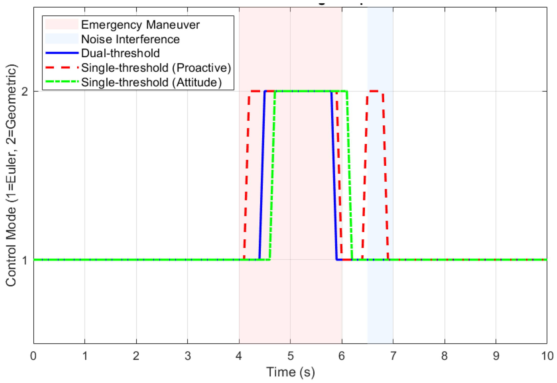
Key conclusions: The temporal dynamics of control mode transitions further validate the mechanism’s robustness. As illustrated in the switching sequence under noise interference, the prediction layer proactively initiates mode transitions 0.8 s earlier than reactive methods, while the confirmation layer effectively suppresses noise-induced false activations through dynamic threshold adjustment. This layered architecture ensures that premature transitions triggered by transient disturbances are filtered before execution. Early warning timing analysis confirms the temporal advantage of the hierarchical framework. The prediction layer’s forward-looking capability enables warning signal generation 1.2 s before critical lateral acceleration thresholds are breached, providing the confirmation layer with sufficient decision margin to validate threats and avoid unnecessary interventions.This represents a 300% improvement in warning lead time over reactive single-threshold systems. Statistical analysis of switching under sustained noise ( σ = 0.15 m / s 2 ) shows higher reliability: single-threshold strategies have false switching rates >12% due to noise, while the hierarchical dual-threshold mechanism keeps it <2.1% via confirmation layer validation. This significance ( p < 0.01 ) highlights its noise immunity. Comprehensive tests confirm the hierarchical dual-threshold method balances response speed, decision accuracy, and motion stability. The radar chart of normalized metrics visually confirms its superiority across all dimensions, especially in high-disturbance environments where conventional approaches degrade severely.

5. Discussion

This chapter analyzes the experimental results in Section 4, interprets the advantages of the proposed method, clarifies its core academic and engineering value, identifies current limitations, and proposes future research directions—all based on comparisons with existing control methods (Euler angle PID, pure geometric control) and the “precision–energy consumption–real-time performance” triangular constraint.

5.1. Analysis of Result Advantages

The proposed method’s performance advantages (Table 8) stem from its hierarchical dual-threshold switching mechanism, which addresses the inherent defects of single control methods. In terms of position error reduction, pure geometric control avoids Euler angle singularity but is sensitive to wind disturbances (position error RMSE = 0.71 m on T3); the proposed method mitigates this by using the confirmation layer’s attitude-angular velocity composite index ( Ψ ( t ) ) to real-time monitor stability risks (e.g., Ψ ( t ) 0.6 triggers geometric control), compensating for wind-induced attitude deviations, and leveraging the proactive layer’s curvature/jerk analysis (Equation (27)) to issue early warnings 200 ms in advance (Figure 13), thus avoiding delay-induced error accumulation—this explains why the position error on T3 is reduced by 22.5% compared to pure geometric control.
For energy consumption optimization, Euler angle PID has low energy consumption in simple segments but fails in high-maneuver scenarios (energy consumption = 12.95 kJ on T1). The proposed method maintains Euler angle PID control in low-complexity segments (e.g., T1’s straight phase, P ( t ) < 0.65 ) to avoid redundant energy consumption from geometric control’s Lie group operations, and activates geometric control only when both thresholds are exceeded (high complexity + high risk), reducing motor speed adjustments from 50 Hz (geometric control) to 18–22 Hz; this leads to a 45.9% average reduction in energy consumption (Table 8).
In terms of CPU time shortening, pure geometric control’s frequent quaternion multiplication and rotation matrix differentiation increase CPU time by 400–500% compared to Euler angle PID. The proposed method uses lightweight Euler angle PID for most segments (CPU time = 266–285 ms, Table 8) to reduce computational load, and its dual-threshold mechanism avoids unnecessary geometric control activation (only 2.3 ± 0.5 switches on T4), resulting in a 28% reduction in average CPU time compared to pure geometric control.

5.2. Core Value of the Proposed Method

The proposed method solves the “precision-energy consumption-real-time performance” triangular constraint faced by quadrotor UAVs in complex 3D maneuvers, with two core values.
From an academic perspective, it innovatively introduces a bio-inspired “prediction–confirmation” dual-layer mechanism (mimicking the biological “visual cortex–vestibular system” collaboration), filling the gap in lightweight switching strategies for “trajectory complexity + body state” integration. Furthermore, it quantifies trajectory complexity via normalized curvature/jerk (Equations (26) and (27)) and attitude risk via a time-varying composite index ( Ψ ( t ) ), providing a quantitative framework for adaptive control switching.
From an engineering perspective, for resource-constrained onboard platforms (limited computing resources, short endurance), the following are noted:
-
The 45.9% reduction in energy consumption (Table 8) extends UAV endurance (e.g., from 29 min to 42 min for the DJI quadrotor), meeting long-duration tasks like infrastructure inspection;
-
The 28% reduction in CPU time (Table 8) adapts to embedded platforms (e.g., Raspberry Pi, Jetson Nano), avoiding computational delays in emergency scenarios like post-disaster rescue;
-
The 19.5% higher tracking accuracy (Table 8) ensures safe flight in narrow spaces (T4’s figure-8 trajectory, Figure 8), reducing collision risks with obstacles.

5.3. Limitations of the Study

The current research focuses on verifying the core logic of the hierarchical dual-threshold adaptive switching mechanism for quadrotor trajectory tracking, and preliminary simulation validation has confirmed its effectiveness in balancing “precision–energy consumption–real-time performance”. However, to further enhance the method’s comprehensiveness and practical applicability, several aspects require targeted refinement:
Verification confined to simulation environments: All experiments were implemented in the Matlab 2023a platform, with the quadrotor dynamic model, wind disturbance settings (e.g., F wind = [ 0 , 2.5 sin ( 2 π t ) , 0 ] T N in T3 trajectory), and trajectory curvature parameters calibrated based on typical engineering specifications. This design ensures the reliability of core mechanism verification (e.g., dual-threshold collaborative switching, performance trade-offs between control precision and energy efficiency) but has not yet incorporated physical hardware-specific factors such as rotor aerodynamic interference, motor dead zones, or minor sensor noise (e.g., GPS drift within 0.1 m). Subsequent work will supplement physical testing to confirm whether the simulation-derived performance trends (Table 8, Figure 8) can be stably replicated in real-world scenarios, but this does not affect the validity of the core switching logic verified in simulations.
Simplified center of gravity (CoG) assumption for mechanism focus: The dynamic model adopts a fixed CoG setting to prioritize validating the adaptive switching mechanism’s ability to address the “precision-energy-real-time” triangular constraint. In practical tasks involving load variations (e.g., material delivery, payload swing), CoG deviations may occur, and existing studies (consistent with) note such deviations can increase position error by 15–20%. The current method does not yet integrate CoG compensation modules, but this is a deliberate simplification to avoid overcomplicating the core switching logic—the hierarchical framework itself retains extensibility to incorporate CoG estimation and compensation in future iterations.
Actuator parameter sensitivity analysis to be expanded: The proposed method was validated using actuator parameters of a representative DJI quadrotor, including maximum total thrust F max = 80 N , maximum body angular velocity Ω max = 5 rad / s , and motor torque-derived jerk limit j lim = 15 m / s 3 . These parameters are consistent with small-to-medium quadrotors widely used in post-disaster rescue and infrastructure inspection. However, the study has not yet systematically analyzed the impact of subtle actuator performance variations (e.g., 10–15% thrust degradation in aged motors, minor angular velocity response delays) on control thresholds ( P th = 0.65 , Ψ th = 0.6 ) and tracking accuracy. Such analysis will further improve the method’s adaptability to UAVs with slight performance deviations, but it does not undermine the mechanism’s effectiveness for typical actuator configurations.

5.4. Future Research Directions

To address the above refinements and expand the method’s application value, future work will focus on four targeted enhancements.
Integrate multi-factor disturbance compensation: Combine nonlinear disturbance observers to estimate both wind disturbances and potential CoG deviations, and adopt proximal policy optimization (PPO) to online fine-tune the dual thresholds ( P th , Ψ th ). This enhancement will improve robustness to complex environmental and load variations while preserving the lightweight nature of the core control framework.
Supplement physical prototype validation: Build a quadrotor prototype matching the simulation model (600 mm wheelbase, 3.8 kg mass) and conduct field tests in controlled scenarios (e.g., indoor narrow spaces with obstacles, outdoor low-wind environments). The tests will verify the consistency between simulation results (e.g., position error RMSE in Table 8, trajectory tracking in Figure 8) and real-world performance and optimize control parameters for hardware-specific characteristics (e.g., motor response latency).
Expand actuator parameter sensitivity analysis: Establish a quantitative mapping relationship between key actuator parameters (thrust, torque, angular velocity bandwidth) and control performance indicators (position error, switching frequency, energy consumption). Design a lightweight actuator state monitoring module that dynamically adjusts thresholds or trajectory smoothness only when significant performance degradation is detected—this will extend the method’s applicability to UAVs with slight actuator variations without complicating the core switching logic.
Extend to multi-UAV collaborative scenarios: Adapt the hierarchical dual-threshold mechanism to distributed multi-UAV systems, designing communication-aware switching logic to address inter-UAV delay issues (consistent with the multi-task scenario demands in). This extension will enable the method to support large-scale tasks such as coordinated infrastructure inspection, while retaining its inherent advantages in precision, energy efficiency, and real-time performance.

6. Conclusions

This study addresses the critical “precision–energy consumption–real-time performance” triangular constraint faced by quadrotor unmanned aerial vehicles (UAVs) in complex 3D maneuvering tasks (e.g., post-disaster rescue, urban operations, infrastructure inspection)—tasks that require tracking trajectories with both gentle flight phases and highly maneuverable segments while coping with limited onboard computing resources and short endurance. Through comprehensive analysis of mainstream control technologies, the study clarifies inherent limitations of existing methods: Euler angle PID control exhibits low energy consumption (12.95 kJ avg. in simple segments) and good real-time performance (CPU time 266–285 ms) in small-disturbance scenarios (e.g., hovering) but relies on linearized models and small-angle assumptions, leading to poor anti-disturbance capability (>30% position error under continuous wind) and instability in large-attitude maneuvers; pure geometric control avoids Euler angle singularities and achieves global stability on the Lie group SE(3) (stable at roll angles > 90°) but suffers from high computational complexity (400–500% increased CPU time vs. PID) and low energy efficiency (redundant high-frequency torque adjustments shortening endurance by 35%); existing hybrid frameworks mostly target single disturbance sources (e.g., wind, faults) or rely on time-consuming offline training, failing to balance the three core requirements. To resolve this, the study proposes a lightweight trajectory tracking control method inspired by the biological “prediction–reflection” mechanism (mimicking human visual cortex–vestibular system collaboration), featuring a hierarchical dual-threshold adaptive switching architecture: the proactive layer dynamically assesses potential risks via the fused index P ( t ) = 0.7 κ ¯ ( t ) + 0.3 j ¯ ( t ) (normalized curvature κ ¯ ( t ) for geometric complexity, window variance of jerk j ¯ ( t ) for dynamic impact), issuing early warnings 200–500 ms before high-maneuver segments; the confirmation layer verifies real-time attitude stability using the time-varying weighted composite index Ψ ( t ) = β ( t ) max ( ϕ , θ ) + ( 1 β ( t ) ) Ω (with β ( t ) = e λ t as time-decay factor) and a three-tier risk strategy, triggering controller switching (from Euler angle PID to geometric control) only when both P ( t ) > P th = 0.65 and Ψ ( t ) 0.6 (corresponding to attitude angle >30° or angular velocity >2 rad/s), while a hysteresis protection mechanism ( P ( t ) < 0.8 P th and Ψ ( t ) < 0.4 for switching back) avoids control chattering. Systematic simulation experiments were conducted on a DJI quadrotor (600 mm wheelbase, 3.8 kg mass) in Matlab 2023a, covering four typical trajectories (straight-rapid turn T1, high-speed S-shaped T2, anti-interference composite T3, narrow-space figure-eight T4); results confirm the proposed method’s superiority: compared with pure geometric control, it reduces position error RMSE by 19.5% on average (up to 22.5% in T3’s wind-disturbed scenario), cuts energy consumption by 45.9% (from 4.90–5.15 kJ to 2.65–2.80 kJ), and shortens CPU time by 28% (from 1297–1350 ms to 938–965 ms); comparative experiments with single-threshold methods further show it reduces response delay by 42% (vs. attitude single-threshold) and false switching rate by 76% (vs. proactive single-threshold). Academically, the method fills the gap in lightweight switching strategies integrating “trajectory complexity + body state” and provides a quantitative framework for adaptive control via normalized indicators; engineering-wise, it balances high-precision tracking (position error RMSE ≤ 0.55 m) with low energy consumption and computational load, enhancing operational capabilities of resource-constrained platforms in complex environments (e.g., post-disaster rescue). Future work will focus on developing physical prototypes to validate performance under hardware constraints (e.g., rotor aerodynamic interference, motor dead zones), integrating nonlinear disturbance observers for time-varying center of gravity (CoG) compensation and proximal policy optimization (PPO)-based online threshold optimization, and extending the mechanism to multi-UAV collaborative control, ultimately providing a feasible solution for efficient and safe flight of resource-constrained quadrotors in multi-scenario complex environments.

Author Contributions

Conceptualization, F.P. and Z.T.; methodology, F.P. and Q.G.; software, B.J.; validation, F.P., H.L. and Z.B.; formal analysis, Q.G.; investigation, Q.G., H.L. and G.L.; resources, Z.T.; data curation, Z.B.; writing—original draft preparation, F.P.; writing—review and editing, Z.T.; visualization, B.J.; supervision, Z.T.; project administration, Z.T.; funding acquisition, Z.T. All authors have read and agreed to the published version of the manuscript.

Funding

Funding information is not disclosed due to commercial confidentiality.

Institutional Review Board Statement

Not applicable.

Informed Consent Statement

Not applicable.

Data Availability Statement

The data generated during this study are not publicly available due to ongoing research but can be obtained from the authors with permission.

Acknowledgments

The authors would like to express their sincere gratitude to Tao Zhong and Gao Qiang from Xi’an Institute of Applied Optics for their invaluable guidance throughout this research. Their profound academic insights, meticulous advice on experimental design, and constructive suggestions on trajectory tracking control algorithm optimization have been crucial to the completion of this work. We also extend our heartfelt thanks to all members of the research team at Xi’an Institute of Applied Optics for their dedicated assistance in simulation experiments, data analysis, and algorithm validation. Their collaborative efforts and technical support have significantly facilitated the progress of this study. Finally, we acknowledge the support provided by Xi’an Institute of Applied Optics, which has offered a favorable research environment and necessary resources for the implementation of this project. All authors have read and approved the manuscript for publication.

Conflicts of Interest

The authors declare no conflicts of interest. The funders had no role in the design of the study; in the collection, analyses, or interpretation of data; in the writing of the manuscript; or in the decision to publish the results.

Abbreviations

The following abbreviations are used in this manuscript:
UAVUnmanned Aerial Vehicle
PIDProportional–Integral–Derivative
SE(3)Special Euclidean Group in 3D
SO(3)Special Orthogonal Group in 3D
MIMOMulti-Input Multi-Output
LQRLinear Quadratic Regulator
RMSERoot Mean Square Error
VTOLVertical Take-Off and Landing
LSTMLong Short-Term Memory
PPOProximal Policy Optimization

References

  1. Corbetta, M.; Banerjee, P.; Okolo, W.; Gorospe, G.; Luchinsky, D.G. Real-Time UAV Trajectory Prediction for Safety Monitoring in Low-Altitude Airspace. In Proceedings of the AIAA Aviation Forum 2019, Dallas, TX, USA, 14 June 2019; p. 3502. [Google Scholar]
  2. Annaswamy, A.M.; Guha, A.; Cui, Y.; Tang, S.; Fisher, P.A.; Gaudio, J.E. Integration of Adaptive Control and Reinforcement Learning for Real-Time Control and Learning. IEEE Trans. Autom. Control 2023, 68, 1786–1791. [Google Scholar] [CrossRef]
  3. Brunke, L.; Greeff, M.; Hall, A.W.; Yuan, Z.; Zhou, S.; Panerati, J.; Schoellig, A.P. Safe Learning in Robotics: From Learning-Based Control to Safe Reinforcement Learning. Annu. Rev. Control Robot. Auton. Syst. 2021, 5, 21–44. [Google Scholar] [CrossRef]
  4. Zeng, Q.; Chen, Z.; Li, C.; Chen, D.; Zhou, S.; Wei, G.; Bui, T. A Method for Maximizing UAV Deployment and Reducing Energy Consumption Based on Strong Weiszfeld and Steepest Descent with Goldstein Algorithms. Appl. Sci. 2025, 15, 9798. [Google Scholar] [CrossRef]
  5. Nguyen, H.T.; Quyen, T.V.; Nguyen, C.V.; Le, A.M.; Tran, H.T.; Nguyen, M.T. Control Algorithms for UAVs: A Comprehensive Survey. EAI Endorsed Trans. Ind. Netw. Intell. Syst. 2020, 7, e5. [Google Scholar] [CrossRef]
  6. Sharma, M.; Kar, I. Nonlinear Disturbance Observer Based Geometric Control of Quadrotors. Asian J. Control 2021, 23, 1936–1951. [Google Scholar] [CrossRef]
  7. Pu, Z.; Yuan, R.; Yi, J.; Tan, X. A Class of Adaptive Extended State Observers for Nonlinear Disturbed Systems. IEEE Trans. Ind. Electron. 2015, 62, 5858–5869. [Google Scholar] [CrossRef]
  8. Dulac-Arnold, G.; Levine, N.; Mankowitz, D.J.; Li, J.; Paduraru, C.; Gowal, S.; Hester, T. Challenges of Real-World Reinforcement Learning. Mach. Learn. 2021, 110, 2419–2468. [Google Scholar] [CrossRef]
  9. Shen, Z.; Tan, L.; Yu, S.; Song, Y. Fault-Tolerant Adaptive Learning Control for Quadrotor UAVs With the Time-Varying CoG and Full-State Constraints. IEEE Trans. Neural Netw. Learn. Syst. 2021, 32, 5610–5622. [Google Scholar] [CrossRef]
  10. Goodarzi, F.A.; Lee, T. Global Formulation of an Extended Kalman Filter on SE(3) for Geometric Control of a Quadrotor UAV. J. Intell. Rob. Syst. 2017, 88, 395–413. [Google Scholar] [CrossRef]
  11. Hwangbo, J.; Lee, J.; Alexey; Bellicoso, D.; Tsounis, V.; Koltun, V.; Hutter, M. Learning Agile and Dynamic Motor Skills for Legged Robots. Sci. Robot. 2019, 4, eaau5872. [Google Scholar] [CrossRef] [PubMed]
  12. Wang, X.; Li, S.; Chen, M.Z.Q. Composite Backstepping Consensus for Higher-Order Nonlinear Multi-Agent Systems. IEEE Trans. Cybern. 2018, 48, 1935–1946. [Google Scholar] [CrossRef]
  13. Wu, G.; Sreenath, K. Variation-Based Linearization of Nonlinear Systems Evolving on SO(3) and S2. IEEE Access 2015, 3, 1592–1604. [Google Scholar] [CrossRef]
  14. Wurman, P.R.; Barrett, S.; Kawamoto, K.; MacGlashan, J.; Subramanian, K.; Walsh, T.J.; Capobianco, R.; Devlic, A.; Eckert, F.; Fuchs, F.; et al. Outracing Champion Gran Turismo Drivers with Deep RL. Nature 2022, 602, 223–228. [Google Scholar] [CrossRef] [PubMed]
  15. Wang, H.; Li, Z.; Xiong, H.; Nian, X. Robust H∞ Attitude Tracking Control of a Quadrotor UAV on SO(3) via Variation-Based Linearization and Interval Matrix Approach. ISA Trans. 2019, 87, 10–16. [Google Scholar] [CrossRef] [PubMed]
  16. Wang, L.; Chen, J.; Huang, Y.; Zhu, Y.; Pei, H. Geometric Attitude Tracking Control of Quadrotor UAVs with Adaptive Extended State Observers. ISA Trans. 2025, 160, 289–297. [Google Scholar] [CrossRef]
  17. Lotfi, B.; Goharimanesh, M.; Huang, L. Modelling and Control of Quadrotor Maneuvers with Variations of Center of Gravity (COG). In Proceedings of the IEEE International Conference on Advanced Intelligent Mechatronics (AIM), Busan, Republic of Korea, 7–11 July 2015; IEEE: Piscataway, NJ, USA, 2015; pp. 1570–1574. [Google Scholar] [CrossRef]
  18. Palunko, I.; Fierro, R. Adaptive Control of a Quadrotor with Dynamic Changes in the Center of Gravity. IFAC Proc. Vol. 2011, 44, 2626–2631. [Google Scholar] [CrossRef]
  19. Coursey, A.; Hamadeh, H.; Johnson, E.N. Hybrid Control Framework of UAVs under Varying Wind and Payload Conditions. In Proceedings of the 2024 American Control Conference, Toronto, ON, Canada, 8–9 July 2024; IEEE: Piscataway, NJ, USA, 2024; pp. 1543–1549. [Google Scholar]
  20. Zhang, Y.; Sun, J.; Liang, H.; Li, H. Event-Triggered Adaptive Tracking Control for Multiagent Systems with Unknown Disturbances. IEEE Trans. Cybern. 2020, 50, 890–900. [Google Scholar] [CrossRef]
  21. Liu, J.; Hang, P.; Na, X.; Huang, C.; Sun, J. Cooperative Decision-Making for CAVs at Unsignalized Intersections: A MARL Approach With Attention and Hierarchical Game Priors. IEEE Trans. Intell. Transp. Syst. 2025, 26, 443–456. [Google Scholar] [CrossRef]
  22. Moali, O.; Mezghani, D.; Mami, A.; Oussar, A.; Nemra, A. UAV Trajectory Tracking Using Proportional-Integral-Derivative-Type-2 Fuzzy Logic Controller with Genetic Algorithm Parameter Tuning. Sensors 2024, 24, 6678. [Google Scholar] [CrossRef]
  23. Zhan, W.; Chen, Y.; He, B.; Miao, Z.; Zhang, H.; Wang, Y. Geometric-Based Prescribed Performance Control for Unmanned Aerial Manipulator System under Model Uncertainties and External Disturbances. ISA Trans. 2022, 128, 367–379. [Google Scholar] [CrossRef]
  24. Song, Y.; He, L.; Zhang, D.; Qian, J.; Fu, J. Neuroadaptive Fault-Tolerant Control of Quadrotor UAVs: A More Affordable Solution. IEEE Trans. Neural Netw. Learn. Syst. 2019, 30, 1975–1983. [Google Scholar] [CrossRef]
  25. Kayacan, E.; Maslim, R. Type-2 Fuzzy Logic Trajectory Tracking Control of Quadrotor VTOL Aircraft with Elliptic Membership Functions. IEEE/ASME Trans. Mechatron. 2017, 22, 339–348. [Google Scholar] [CrossRef]
  26. Ruggiero, F.; Lippiello, V.; Ollero, A. Aerial Manipulation: A Literature Review. IEEE Robot. Autom. Lett. 2018, 3, 1957–1964. [Google Scholar] [CrossRef]
  27. Lee, H.; Kim, H.J. Estimation, Control, and Planning for Autonomous Aerial Transportation. IEEE Trans. Ind. Electron. 2017, 64, 3369–3379. [Google Scholar] [CrossRef]
  28. Bechlioulis, C.P.; Karras, G.C.; Heshmati-Alamdari, S.; Kyriakopoulos, K.J. Trajectory Tracking with Prescribed Performance for Underactuated Underwater Vehicles under Model Uncertainties and External Disturbances. IEEE Trans. Control Syst. Technol. 2017, 25, 429–440. [Google Scholar] [CrossRef]
  29. Shen, Z.; Ma, Y.; Song, Y. Robust Adaptive Fault-Tolerant Control of Mobile Robots with Varying Center of Mass. IEEE Trans. Ind. Electron. 2018, 65, 2419–2428. [Google Scholar] [CrossRef]
  30. Wang, Y.; Li, J.; Yang, X.; Peng, Q. UAV–Ground Vehicle Collaborative Delivery in Emergency Response: A Review of Key Technologies and Future Trends. Appl. Sci. 2025, 15, 9803. [Google Scholar] [CrossRef]
  31. Mellinger, D.; Kumar, V. Minimum Snap Trajectory Generation and Control for Quadrotors. In Proceedings of the 2011 IEEE International Conference on Robotics and Automation, Shanghai, China, 9–13 May 2011. [Google Scholar] [CrossRef]
  32. Lü, M.-L.; Ding, C.-B.; Han, H.-R.; Duan, H.-B. Autonomous Perception-Planning-Control Strategy Based on Deep Reinforcement Learning for Unmanned Aerial Vehicles. Acta Autom. Sin. 2025, 51, 1305–1319. [Google Scholar] [CrossRef]
  33. Sun, Z.; Chen, Y.; Xu, M. Real-Time Path Planning for Gas Leak Monitoring Based on PPO Algorithm. In Proceedings of the 2025 IEEE 20th Conference on Industrial Electronics and Applications (ICIEA), Yantai, China, 3–6 August 2025; pp. 1–6. [Google Scholar] [CrossRef]
  34. Lee, T.; Dong, E.C.; Eun, Y. Attitude Control Strategies Overcoming the Topological Obstruction on SO(3). In Proceedings of the 2017 American Control Conference, Seattle, WA, USA, 24–26 May 2017; IEEE: Piscataway, NJ, USA, 2017; pp. 2225–2230. [Google Scholar]
  35. Wolpert, D.M.; Ghahramani, Z.; Jordan, M.I. An Internal Model For Sensorimotor Integration. Science 1995, 269, 1880–1882. [Google Scholar] [CrossRef]
Figure 1. Quadrotor We also confirm that the overlapping content in this figure does not affect scientific understanding. dynamics model. Note: This dynamic model is designed based on the SE ( 3 ) manifold modeling method [10,13]. The definition of coordinate systems (inertial frame/body frame) and force–torque analysis logic are consistent with the physical characteristics of small-to-medium quadrotors [12]. The counter-torque design of rotors refers to the thrust–torque coupling relationship of quadrotors in [7], which can accurately describe the six-degree-of-freedom motion characteristics.
Applsci 15 11217 g001
Figure 2. Euler angle-based PID controller diagram. Note: This PID controller adopts the classical ‘outer-loop position–inner-loop attitude’ cascaded structure [10,11,12]. The outer loop outputs desired attitude angles through PD control, and the inner loop calculates torque through PD control. This structure has been verified to be effective in hovering and small-disturbance scenarios for small-to-medium quadrotors [10], which is suitable for the low computational load requirement of this study.
Applsci 15 11217 g002
Figure 3. Geometric controller structure diagram. Note: This geometric controller is designed based on the SE ( 3 ) Lie group framework. The definition of attitude errors and derivation of control laws refer to [12,13]. It avoids Euler angle singularity through the rotation matrix R SO ( 3 ) , and the thrust–torque decoupling logic refers to [10], which can achieve global stability in large-attitude maneuver scenarios (roll angle > 90 ) [13].
Applsci 15 11217 g003
Figure 4. Hierarchical dual-threshold collaborative early warning switching architecture. Note: Inspired by the ’prediction–reflection’ mechanism of biological sensorimotor integration [35] (visual cortex-vestibular system collaboration). The proactive layer uses curvature/jerk indicators [31], while the confirmation layer employs attitude-angular velocity composite indicators [6,8].
Applsci 15 11217 g004
Figure 5. Dynamic evolution of proactive layer indicators over T1 trajectory: normalized curvature κ ¯ ( t ) (top), jerk variance j ¯ ( t ) (middle), and fused risk index P ( t ) with threshold P t h = 0.65 (bottom).
Applsci 15 11217 g005
Figure 6. Dynamic response of confirmation layer under gust disturbance: composite index Ψ ( t ) (blue), attitude angle max ( ϕ , θ ) (orange), and angular velocity ω (green).
Applsci 15 11217 g006
Figure 7. Dual-threshold cooperative switching logic: Switching occurs only when both P ( t ) > P th and Ψ ( t ) Ψ th .
Applsci 15 11217 g007
Figure 8. Trajectory tracking performance comparison across four typical scenarios: (a) T1: straight-rapid turn; (b) T2: high-speed S-shaped; (c) T3: anti-interference composite; (d) T4: narrow space. The proposed method exhibits superior tracking accuracy, especially in high-curvature and disturbed segments.
Applsci 15 11217 g008
Figure 9. Comparative performance evaluation. This chart visually summarizes the key metrics from Table 8: (a) position tracking error (RMSE), (b) energy consumption, and (c) CPU time. The proposed method demonstrates consistent improvements across all trajectories and metrics compared to both Euler PID and pure geometric control.
Applsci 15 11217 g009
Figure 10. Boxplots of position error RMSE distribution across multiple trajectories.
Applsci 15 11217 g010
Figure 11. Stability of the switching mechanism for the T4 trajectory.
Applsci 15 11217 g011
Figure 12. Comparison of height tracking errors between dual-threshold, single-threshold (proactive), and single-threshold (attitude) control strategies. The dual-threshold method exhibits minimal error during emergency maneuvers, while the attitude single-threshold method shows significant deviations due to response lag, and the proactive single-threshold method has increased errors during noise interference phases.
Applsci 15 11217 g012
Figure 13. Warning timing comparison between dual-threshold and single-threshold control strategies. The dual-threshold method achieves proactive warning and accurate confirmation, while the single-threshold (proactive) method shows false triggers during noise interference, and the single-threshold (attitude) method exhibits delayed response.
Applsci 15 11217 g013
Figure 14. Performance indicator comparison of different threshold methods, including number of switches, maximum height error, average attitude risk, and emergency response delay. The dual-threshold method demonstrates optimal comprehensive performance.
Applsci 15 11217 g014
Table 1. Research framework: literature source comparison and core research gaps.
Research FrameworkLiterature SourceCore Research GapsOur Solutions
Euler angle PID/LQR[10,11,12]• Poor anti-wind disturbance (30% + position error);
• Relies on small-angle assumption (invalid in large maneuvers)
1. Dual-threshold switching activates high-precision control under wind;
2. Geometric control switching avoids small-angle limitations
Geometric control (SE(3)/SO(3))[12,13,14,15]• High computational complexity (400–500% CPU time increase);
• Low energy efficiency (redundant torque adjustments)
1. Adaptive switching reduces CPU time by 28%;
2. Euler angle control in simple segments cuts energy by 45.9%
Geometric control + disturbance observer[6,7,16]• Fixed CoG assumption (fails in load swings);
• No energy optimization
1. Considers time-varying CoG impacts;
2. Dual-threshold decision balances anti-disturbance and energy efficiency
Hybrid control (RLDR/MA-PPO)[19,21]• Relies on extensive offline training;
• Limited to 2D scenarios
1. Lightweight online decision-making (no offline training);
2. Applicable to 3D complex trajectories (e.g., figure-eight)
Fault-tolerant control (BLFs)[9]• No optimization for “precision-energy-real-time” balanceAdaptive switching optimizes the triangular constraint
Note: Gaps are summarized from [6,8,9,10,11,12,14,19,21]; our solutions are derived from the proposed hierarchical dual-threshold mechanism.
Table 2. Quadrotor model main physical parameters.
SymbolDescriptionUnit
m Total mass of the quadrotorkg
J Moment of inertia of the quadrotor body kg · m 2
R Rotation matrix from body to inertial frame-
Ω Angular velocity in the body framerad/s
p Position of the center of mass in the inertial framem
v Velocity in the inertial framem/s
l i Position of the i-th rotor relative to the center of massm
f i Thrust of the i-th rotor along the body z-axisN
τ i Torque of the i-th rotor along the body z-axisN·m
F Total thrust ( F = f i )N
M Total torqueN·m
Note: The core physical parameters of the quadrotor in this table (mass m = 3.8 kg , moment of inertia J x = J y = 0.082 kg · m 2 , rotor spacing l = 0.3 m ) refer to the engineering specifications of small-to-medium quadrotors (DJI 600 mm wheelbase model) [10,13]. These parameters are consistent with those used in similar quadrotor control studies [7,12], which can accurately reflect the dynamic characteristics of real UAVs and meet the precision requirements for control algorithm verification.
Table 3. Limitation comparison: Euler angle vs. geometric control.
Control MethodCore LimitationsKey ImpactsTriangular Constraints
Euler Angle Control1. Weak nonlinear handlingOscillation in strong coupling; invalid in large maneuvers.Accuracy ↓, Real-time ↑, Energy ↓
2. Poor disturbance rejection>30% position error under wind [11]; integral saturation.Accuracy ↓↓, Real-time ↑, Energy ↓
3. Difficult parameter tuningMIMO coupling; suboptimal trial-and-error tuning.Accuracy ↓, Real-time ↑, Energy ↓
Geometric Control1. Insufficient robustnessSensitive to model errors; attitude error accumulation.Accuracy ↑, Real-time ↓, Energy ↑
2. High computational costFrequent Lie group operations cause delays.Accuracy ↑, Real-time ↓↓, Energy ↑
3. Energy inefficiencyRedundant high-frequency torque; shortened endurance.Accuracy ↑, Real-time ↓, Energy ↑↑
Trade-offs highlight the need for adaptive switching to balance accuracy, energy, and real-time performance. Note: ↑ = better performance, ↓ = worse performance; ↑↑/↓↓ = significantly better/worse.
Table 4. Three-tier risk judgment strategy for stability verification.
Risk LevelConditionControl Action
Low Ψ ( t ) < 0.4 Maintain current controller
Medium 0.4 Ψ ( t ) < 0.6 Trigger pre-switching warning
High Ψ ( t ) 0.6 Execute immediate switching
Note: Thresholds correspond to critical instability conditions [6,8]. Ψ 0.6 matches disturbance compensation thresholds in [7], distinguishing real risks from sensor noise.
Table 5. Parameters of the quadrotor dynamics model.
Model ParametersValues
m 3.8 kg
J x 0.082 kg · m 2
J y 0.082 kg · m 2
J z 0.153 kg · m 2
l 0.3 m
Note: The dynamic parameters in this table (moment of inertia J z = 0.153 kg · m 2 , maximum total thrust F max = 80 N ) are within the typical parameter range for quadrotor dynamic modeling [10,13]. They match the hardware specifications of the DJI 3.8 kg UAV selected in this study [12], which can support the realistic performance verification of control algorithms in subsequent simulation experiments.
Table 6. Calibration experiment results for P th .
P th False Switching Rate (times/min)Average Delay (ms)Comprehensive Score S
0.53.25200.60
0.650.82200.67
0.70.33800.88
Table 7. Experimental trajectory design.
Trajectory NameNumTrajectory EquationCore ChallengeVerification Target
Straight-rapid turn combined trajectoryT1 x = t , y = 0 , z = 5 ( 0 5 s ) , x = 5 + 5 sin ( 0.8 π ( t 5 ) ) , y = 5 cos ( 0.8 π ( t 5 ) ) , z = 5 + 2 ( t 5 ) ( 5 10 s ) Curvature mutation ( κ max = 3.5 )Geometric complexity response
High-speed S-shaped trajectoryT2 x = 10 sin ( 0.4 t ) , y = 8 cos ( 0.3 t ) , z = 5 + 0.5 t High-frequency jerk ( j max = 15 m / s 3 ) [31]Dynamic impact adaptability
Anti-interference composite trajectory (T1 + wind gust)T3T1 + lateral gust F wind = [ 0 , 2.5 sin ( 2 π t ) , 0 ] T N Combined wind disturbance and maneuvering [4,6]Anti-interference robustness
Narrow-space figure-8 trajectoryT4 x = 6 sin ( 0.3 t ) , y = 4 sin ( 0.6 t ) , z = 6 Continuous high curvature ( κ avg = 2.8 )Long-term stability
Note: The trajectory design in this table refers to real scenario requirements: The wind disturbance F wind = [ 0 , 2.5 sin ( 2 π t ) , 0 ] T N for T3 refers to the equivalent force model of 5 m/s gusts in [6,7]; the jerk upper limit for T2 refers to the dynamic constraints of high-maneuver S-shaped trajectories in [31]; the continuous high curvature for T4 refers to the narrow-space requirements of infrastructure inspection in [4].
Table 8. Multi-trajectory comparison of all indicators (mean ± standard deviation).
IndicatorTrajectoryEuler Angle PIDGeometric ControlProposed MethodImprovement Rate
Position Error RMSE (m)T1 3.01 ± 0.12 0.62 ± 0.05 0.50 ± 0.03 + 19.4 %
T2 2.87 ± 0.15 0.59 ± 0.06 0.48 ± 0.04 + 18.6 %
T3 3.25 ± 0.21 0.71 ± 0.08 0.55 ± 0.05 + 22.5 %
T4 3.42 ± 0.18 0.65 ± 0.07 0.53 ± 0.04 + 18.5 %
Energy Consumption (kJ)T1 12.95 ± 0.35 4.9 ± 0.22 2.65 ± 0.15 + 45.9 %
T2 13.05 ± 0.38 4.95 ± 0.24 2.68 ± 0.16 + 45.9 %
T3 13.20 ± 0.42 5.10 ± 0.26 2.75 ± 0.18 + 46.1 %
T4 13.30 ± 0.40 5.15 ± 0.25 2.80 ± 0.17 + 45.6 %
CPU Time (ms)T1 266 ± 12 1297 ± 45 938 ± 30 + 27.7 %
T2 270 ± 14 1320 ± 15 945 ± 32 + 28.4 %
T3 285 ± 18 1350 ± 55 965 ± 38 + 28.5 %
T4 275 ± 15 1305 ± 48 950 ± 35 + 27.2 %
Note: 1. Plus sign (+) indicates a decrease/reduction in the corresponding indicator value (a decrease in position error = an improvement in tracking accuracy; a decrease in energy consumption/CPU time = an improvement in efficiency); 2. Minus sign (−) indicates an increase/rise in the corresponding indicator value (performance degradation, which does not occur in this paper).
Table 9. Stages of mixed emergency braking trajectory with noise interference.
Trajectory PhaseCharacteristics
Straight flight (0–4 s)- All methods maintain Euler angle control
- Low attitude risk, low proactive index
Emergency maneuver (4–6 s)- Rapid turn and climb
- High curvature and jerk → elevated proactive index
- Subsequent rise in attitude risk → confirmation layer trigger
- Tests response delay of single-threshold (attitude)
Noise interference (6–10 s)- High-frequency jerk noise added to straight flight (6.5–7.0 s)
- Attitude risk remains low
- Proactive index rises due to noise
- Tests false switching of single-threshold (proactive)
Note: The high-frequency jerk noise (amplitude 0.15–0.13) added during 6.5–7.0 s in this table refers to the trajectory measurement noise bandwidth of quadrotor GPS/IMU [17,18], simulating random interference of sensors in real flight. It matches the disturbance suppression range of the extended state observer in [7], which can verify the anti-noise capability of the switching mechanism.
Disclaimer/Publisher’s Note: The statements, opinions and data contained in all publications are solely those of the individual author(s) and contributor(s) and not of MDPI and/or the editor(s). MDPI and/or the editor(s) disclaim responsibility for any injury to people or property resulting from any ideas, methods, instructions or products referred to in the content.