1. Introduction
Recent advancements in radar systems have resulted in a significant enhancement in the capacity to detect aircraft at an early stage. The radar cross section (RCS) of an object is a key factor in determining its visibility to radar systems. Reducing the RCS, a critical component of stealth technology, can provide a significant tactical advantage. The concept of low visibility is realized through the integration of design, materials, and technologies that absorb or deflect radar waves [
1]. Thus, aircraft become more difficult to detect, reducing enemy response times and enhancing mission effectiveness. It is evident that a low RCS has a direct impact on survivability and operational success in modern airspace [
2].
A frequency-selective surface (FSS) is an important technology for reducing RCS. It allows the transmission of specific frequencies while blocking others. Hence, it is highly advantageous for the purpose of targeted radar signature control [
3]. Unlike basic methods such as shaping [
4], absorbing materials [
5], or cancellation techniques [
6], FSSs offer frequency-specific performance and can redirect reflected waves away from threat directions. They also support functions like improving antenna performance, which is valuable for multi-purpose military platforms. Their ability to conform to existing aircraft designs without affecting aerodynamics enhances their practicality. Within the context of dynamic electronic warfare environments, an FSS can be tuned to adapt to changing threats. For this reason, an FSS is a reasonable choice in modern defense applications [
7].
It is important to note that an FSS is typically designed for flat structures. However, performance may decline when it is applied to curved forms [
8]. This limitation, along with production and simulation difficulties, could limit its overall effectiveness. While the electromagnetic behavior of flat surfaces is relatively easy to predict, sloped or complex shapes introduce greater modeling difficulty. Yet, the increasingly intricate geometry of modern aircraft necessitates conformal implementations. Conformal FSSs, which match the surface shape, can enhance electromagnetic interaction and improve performance. Therefore, their development and integration are essential for the future design and operational success of advanced aircraft platforms [
9].
On the other hand, due to its superior filtering capabilities, FSSs are widely applied in various applications, including radomes [
10], lenses [
11], and reflectors [
12]. In military applications, airborne radomes are particularly significant as they shield radar components from environmental effects [
13]. To meet the demands of modern radar systems, radomes incorporating FSSs with bandpass characteristics have been introduced, enabling transmission at desired frequencies while suppressing out-of-band signals [
14]. Despite the existence of numerous bandpass FSS designs, the majority are confined to planar configurations [
15,
16]. In practice, radomes often possess curved surfaces, necessitating the use of FSSs to maintain stable transmission under conformal conditions. Importantly, angular stability under such curvature is also critical, as it contributes to reducing the RCS by minimizing undesired scattering [
17]. Therefore, researchers developing a conformal-bandpass FSS should aim not only to maintain consistent electromagnetic performance but also to overcome fabrication challenges by providing cost-effective and easily manufacturable solutions suitable for practical integration [
18].
In this study, a simulation design for a conformal bandpass FSS in radome applications is proposed to address the aforementioned challenges. In this context, a bandpass FSS operating in the 8–12 GHz range was designed and subsequently integrated into a conical radome geometry to evaluate its electromagnetic performance. The FSS-integrated radome was then compared with a conductive counterpart through monostatic RCS analyses to assess the impact on radar visibility. The results confirm that the proposed design effectively reduces radar reflections while maintaining signal transparency within the operational band. This demonstrates that the proposed design offers a practical and novel perspective on RCS-aware FSS radome development.
The remainder of this paper is structured as follows. The following section provides an overview of existing work in the literature and outlines the contributions of this study. Then, the proposed design for a conformal-bandpass FSS is introduced in
Section 3. In
Section 4, the effectiveness of the integrated FSS in reducing the RCS of the conical radome structure is analyzed in detail. Next, in
Section 5, the results are discussed, along with the limitations and directions for future work. In
Section 6, conclusions are drawn.
2. Related Work and Contributions
In recent years, FSSs have gained significant attention in the development of advanced radome structures due to their capability to manipulate electromagnetic wave transmission and reflection characteristics. Numerous FSS designs have been proposed to improve parameters such as bandwidth, angular stability, and mechanical conformability, particularly for radar and airborne applications. Researchers have explored diverse unit cell geometries, optimization techniques, and fabrication methods to achieve high-performance bandpass behavior while maintaining structural compatibility with planar and conformal surfaces [
7]. This section reviews recent studies that highlight key contributions in conformal-bandpass FSS design, modeling, and implementation for radome applications.
In ref. [
19], a conformal triangular cone-like bandpass FSS radome was designed using annular apertures as unit structures. By analyzing the effects of unit size, grating lobes, arrangement, and dielectric thickness, an optimized configuration was obtained. The resulting design exhibited high transmittance and gain within the 750 MHz antenna bandwidth, while effectively reflecting out-of-band signals, demonstrating strong bandpass filtering characteristics.
A broadband A-sandwich radome wall structure incorporating a bandpass FSS composed of dual square conducting rings for airborne radar applications was proposed in ref. [
20]. The structure that features a Nomex honeycomb core and Quartz skin layers, achieved a 40.8% impedance bandwidth (7.8–11.8 GHz) with sharp roll-off, under various incidence angles and polarizations. Both unit cell and conformal analyses confirmed its high electromagnetic performance and suitability for airborne radome design.
The study presented in ref. [
21] was devoted to investigate RCS of an aircraft by incorporating the electromagnetic characteristics of an FSS radome. High-frequency methods such as the shooting and bouncing rays (SBR), physical theory of diffraction (PTD), and flat modeling were employed for computational efficiency. Monostatic and bistatic RCSs were analyzed for different radome types and polarizations, and the results were validated against commercial electromagnetic (EM) simulation tools. The findings highlighted the importance of accounting for radome EM effects to achieve accurate RCS predictions.
In ref. [
22], the performance of an airborne antenna using an FSS as a bandpass filter was analyzed in both planar and conformal configurations. Unit cell simulations with Floquet boundary conditions revealed polarization-independent behavior and strong angular stability. A 3 × 3 FSS array was implemented to evaluate antenna gain and insertion loss across the frequency band, showing improved gain performance with FSS integration.
A rapid modeling method for airborne FSS radomes was introduced in ref. [
23], using customizable primitives supported by parametric entity features. The approach automates modeling of dielectric layers, the FSS layer, and the complete structure, enabling flexible and precise radome contour representation. The simulation results showed that the method could significantly reduce modeling time and improve efficiency compared to traditional techniques.
A finite conformal FSS design was presented in ref. [
24] based on equivalent circuit modeling. The study investigated the stability of different FSS elements and resulted in a compact wideband FSS optimized for the X-band. Both simulations and experimental results confirmed stable performance under bending and at varying incidence angles.
In ref. [
25], a bandpass FSS design for X-band radar communication applications was proposed. In its design, three resonators were used to extend the bandwidth, covering the entire X-band with 70% transmittance. The Fireflies-based metaheuristic optimization algorithm was employed to optimize geometric parameters, achieving wide fractional bandwidth, low insertion loss, and high return loss. The FSS has been shown to be angularly stable up to 60° and to maintain its performance under bending conditions.
A mapping technique for placing unit cells uniformly on double-curved FSS surfaces was introduced in ref. [
26]. The method was demonstrated by designing a paraboloid-shaped bandpass FSS for radome applications. A complementary circular Jerusalem Cross was used as the unit cell, showing a narrowband response at 10 GHz with 0.4 dB insertion loss. The curved structure was analyzed using the finite element boundary integral method, which was then fabricated using 3D printing. Measured results aligned well with simulations and showed stable performance up to a 75° incident angle.
A comparative summary of recent studies on conformal-bandpass FSS radomes is provided in
Table 1. As observed, these studies have primarily emphasized electromagnetic performance indicators such as bandwidth, insertion loss, and angular stability. Many of the designs presented in the studies, however, rely on multilayered or configurations. While these configurations may offer high electromagnetic performance, they typically result in increased fabrication complexity, cost, and potential limitations in real-world manufacturability.
In contrast, the FSS design proposed in this study focuses on both electromagnetic efficiency and practical feasibility. The ring-and-patch structure used in the proposed FSS design employs a simpler, more manufacturable unit cell geometry that enables easier integration into conformal radome forms. More specifically, as can be seen from the table, the structure offers low insertion loss (0 dB) and stable performance within the 8–12 GHz range, while maintaining structural simplicity and low fabrication complexity. Compared to existing designs, it can be more suitable for scalable and cost-effective production, which is a critical consideration for deployment in aerospace and defense applications.
On the other hand, RCS analysis to assess radar visibility reduction is rarely addressed in existing studies on conformal-bandpass FSS radomes [
21], although minimizing radar visibility is one of the key requirements for low-observable platforms. In this study, the effectiveness of the proposed design in minimizing radar visibility is demonstrated by integrating it into a conical radome geometry and conducting monostatic RCS simulations. Therefore, the major contribution of this study is integration of the designed FSS into a realistic radome of next generation aircrafts, featuring challenging conical geometry, while maintaining stable electromagnetic performance across the entire X-band (8–12 GHz) during this integration. We believe that the combined focus on design manufacturability and RCS performance may fill an important gap in the literature, offering a balanced and application-oriented solution for advanced radome development.
3. Design
The ring and patch geometries were chosen for the FSS design due to their several advantages in conformal and high-frequency applications. These geometrical elements directly affect the electromagnetic performance and adaptability of the FSS, both of which are critical to the intended application areas. Owing to their structural simplicity and inherent flexibility, ring and patch configurations provide an optimal solution for conformal implementations. These designs can conform to non-planar surfaces, such as cylindrical or spherical geometries, with minimal electromagnetic performance degradation [
3]. This characteristic makes them highly suitable for FSS implementations that must operate reliably within narrow or predefined frequency bands.
The advantages of ring and patch structures in conformal applications primarily arise from the flexibility of both their geometry and the materials commonly employed in their fabrication. This flexibility facilitates the integration of antennas and other electromagnetic components onto curved or irregular surfaces without requiring significant modifications to the design. Moreover, these structures play a pivotal role in the manipulation and filtering of electromagnetic waves, which is crucial for enhancing system performance. The resonant frequencies of ring and patch elements can be readily tuned by altering their physical dimensions, making them particularly advantageous for applications such as satellite communications, radar systems, and other high-frequency technologies [
27].
In practice, another reason for choosing ring and patch elements is their manufacturing efficiency. Compared to complex frequency selective surface configurations, such as fractal or multilayer structures, ring and patch designs are easier and more cost-effective to fabricate. This is especially important for large-scale or industrial deployments, where both production speed and cost control are essential. As a result, using ring and patch geometries may improve electromagnetic performance. Moreover, their simplicity may accelerate the prototyping and deployment process, enhancing the scalability of the system in real-world applications.
The following sections present the unit cell design methodology in detail, followed by the implementation and analysis of the conical FSS radome configuration.
3.1. Unit-Cell Design
The configuration of the proposed FSS unit cell is illustrated in
Figure 1, along with the excitation directions and the applied boundary conditions. The unit cell is designed as a square frame patterned on a Rogers RO4003C substrate manufactured by Rogers Corporation, headquartered in Chandler, AZ, USA. It is metallized with copper on one side and incorporates a centrally positioned circular patch. The substrate has a thickness (
) of 0.508 mm and a relative permittivity
of 3.55. Besides, the side length (
) of the dielectric substrate is 10 mm, the diameter (
) of the circular copper patch is 3.15 mm, and the width of the metallic patch (
) is 0.4 mm. The copper cladding used in the design has a thickness (
) of 35 µm. A list of the design parameters is presented in
Table 2.
The determination of these parameters was not arbitrary but the result of a comprehensive design and optimization process. Electromagnetic simulations were performed using a commercial design suit (CST Studio Suite) to systematically investigate the influence of each geometrical parameter on the resonant frequency and bandwidth. Through this iterative analysis, the optimal parameter set was identified to achieve the desired bandpass behavior in the X-band.
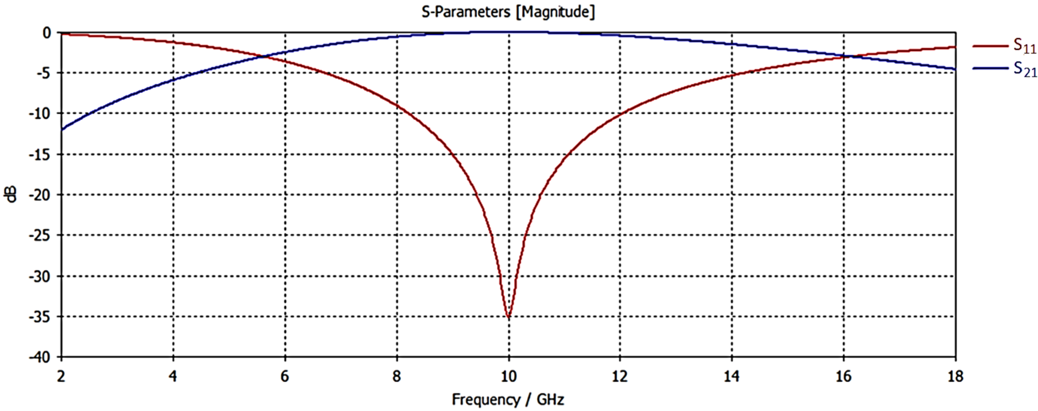
Figure 2 shows the reflection (
) and transmission (
) coefficients obtained from the simulations, confirming the frequency-selective behavior of the structure. As shown in the figure, the designed unit cell demonstrates bandpass characteristics, with a 10-dB bandwidth of approximately 4 GHz within the X-band.
The simulations were performed using periodic boundary conditions and Floquet ports in CST Studio Suite. Since the periodicity of the proposed structure is smaller than half of the free-space wavelength across the 8–12 GHz range, only the zeroth-order Floquet modes (specular reflection and transmission) are propagating, while all higher-order modes remain evanescent. Therefore, the and parameters represent the specular components of the scattered field. This assumption is consistent with conventional FSS analyses, where subwavelength periodicity ensures that higher-order modes remain below their cutoff frequencies and can be neglected.
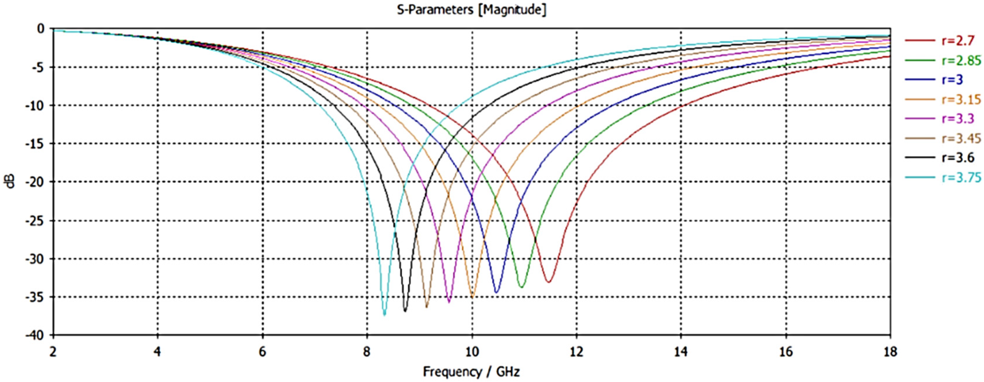
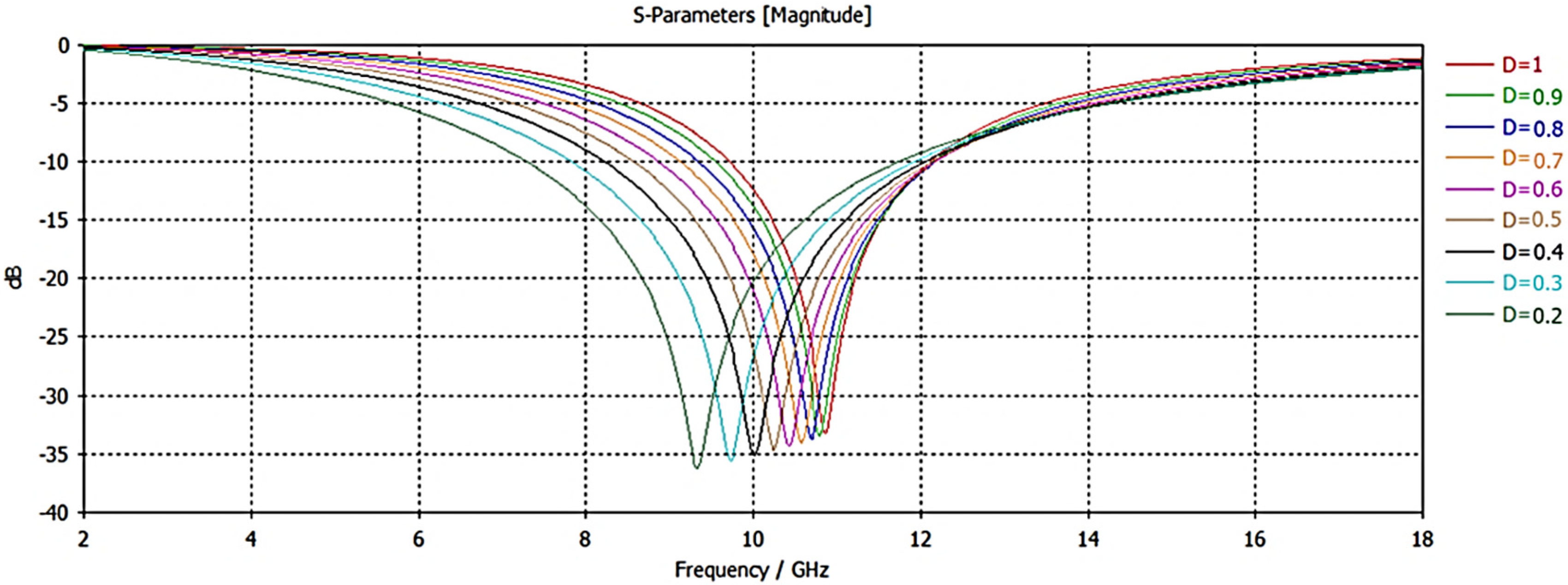
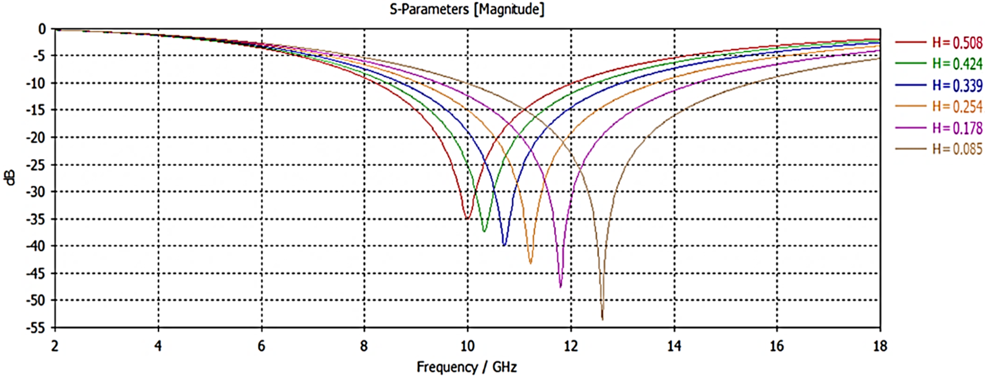
During the design phase, the effect of geometrical variations on the resonant frequency and bandwidth was thoroughly investigated. Specifically, the influence of the circular patch diameter, patch width, and dielectric thickness on the
response was analyzed (
Figure 3,
Figure 4 and
Figure 5) to achieve the target performance characteristics. These parametric studies ensured that the final design parameters were selected based on a rigorous assessment of trade-offs between resonant stability, bandwidth control, and fabrication feasibility.
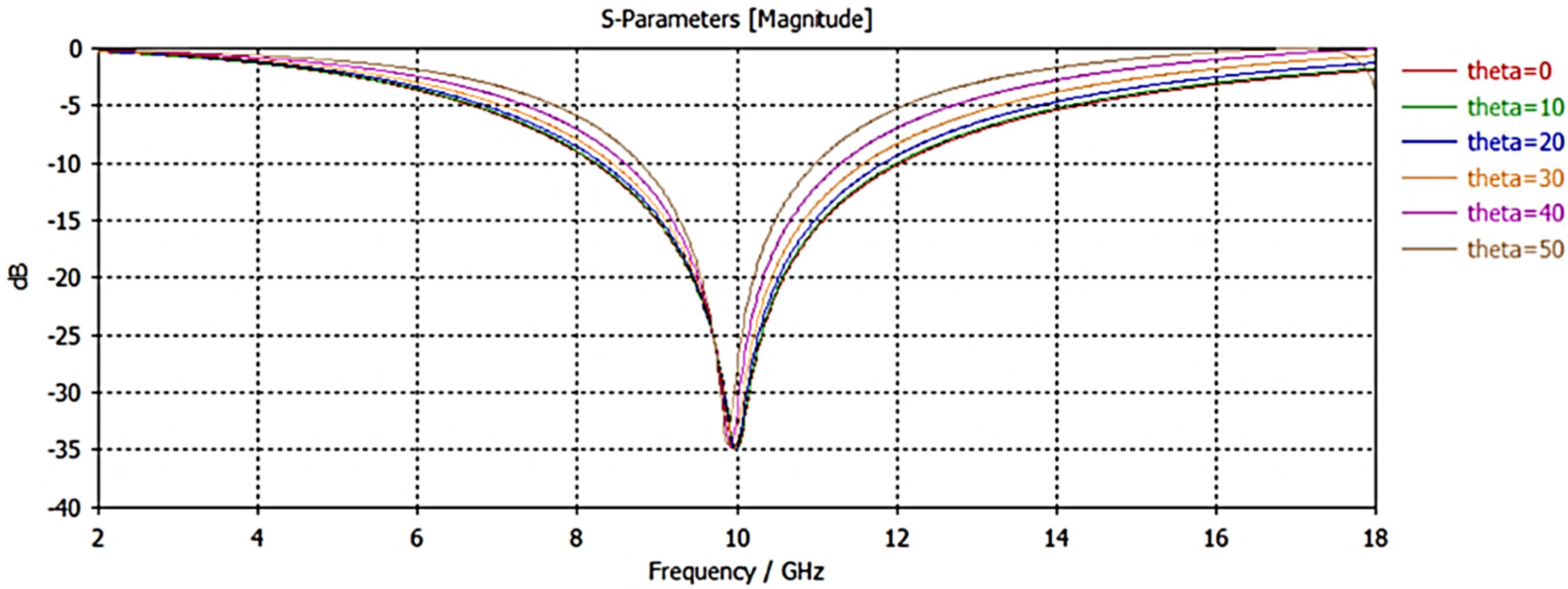
Moreover, the angular stability of the unit cell was examined by evaluating the reflection characteristics at various incidence angles (
). As illustrated in
Figure 6, the structure maintains stable reflection properties up to
50°. This offers that the unit cell maintains high performance over a wide angular range. The reflection characteristics observed within this range indicate that the design has strong potential for use in conformal applications, as it can be effectively integrated onto various curved surfaces. Therefore, the combination of broadband filtering, angular stability, and structural simplicity highlights the proposed unit cell as both an effective and practically manufacturable solution for conformal FSS radome applications.
3.2. Conical FSS Radome Design
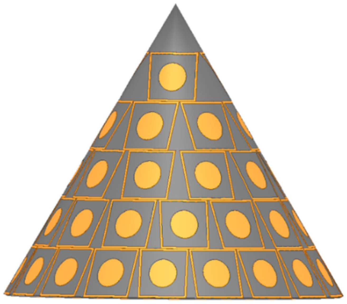
Due to the complex interaction between incident electromagnetic waves and the curved geometry of the structure, the design of a conformal FSS radome requires electromagnetic simulations. These simulations are critical for improving radar system performance and ensuring efficient spectral management, especially in scenarios involving broadband operation and varying incidence angles. In this study, the bandpass FSS, designed to operate effectively within the 8–12 GHz frequency range, was conformally mapped onto a conical radome to evaluate its functional viability in realistic, non-planar applications.
The FSS unit cells were arranged on the conical surface while maintaining approximate periodicity to ensure consistent electromagnetic behavior across the structure. The cone has a base diameter of 70 mm and a height of 60 mm. It was modeled using the same material configuration as the planar unit cell design, consisting of a Rogers RO4003C substrate and copper metallization, in order to preserve the dielectric and conductive properties. The layout was designed to accommodate the curvature while minimizing distortions to the unit cell geometry.
Figure 7 illustrates the final conformal configuration, where the circular patch elements are clearly visible on the segmented metallic frames distributed across the conical surface. This visual representation demonstrates the structural uniformity and integration fidelity of the unit cells on the cone surface, thus validating the feasibility of the proposed conformal approach.
4. Analysis of RCS Reduction
In this section, the RCS characteristics of the proposed conformal FSS radome are analyzed in detail. The aim is to evaluate the effectiveness of the integrated FSS in reducing the RCS of the conical radome structure over a broad frequency range. To this end, the RCS of the designed conformal radome structure integrated with the FSS was analyzed using the SBR technique [
28]. The SBR technique incorporates physical optics (PO), geometric optics (GO), and ray-tracing algorithms. Thus, it provides more realistic analysis results compared to other high-frequency techniques.
In the SBR technique, incident rays are first traced to their intersection points on the target surface using GO principles. At these points, the induced surface currents are determined by applying PO integrals, and the resulting currents are then employed to compute the scattered fields. This iterative process continues until the predefined maximum number of bounces for the SBR simulation is reached. Therefore, owing to its capability to account for multiple reflections and diffractions as well as its computational efficiency, the SBR method was adopted to evaluate the RCS performance of the proposed conformal FSS radome design.
In the following sections, the validation of the adopted RCS analysis method is presented, ensuring the reliability of the simulation framework. Then, the RCS performance of the conductive radome and the FSS-integrated radome is comparatively investigated through monostatic analyses to provide insights into the influence of the proposed design on radar visibility.
4.1. Validation of the RCS Analysis Method
The geometrical NASA Almond model [
29] is a widely adopted benchmark for RCS calculations. This model provides a consistent framework for conducting RCS simulations and measurements. It can be used as a reference to assess the accuracy of different techniques and algorithms. For instance, in ref. [
30], RCS results were evaluated using the NASA Almond model in the context of the SBR approach and the multi-level fast multipole method (MLFMM).
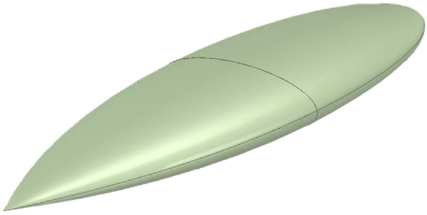
In this study, the applied RCS analysis method was validated by calculating the RCS of the NASA Almond model using the SBR+ technique. The geometry of NASA Almond model that was used in this study shown in
Figure 8. Simulations were performed in ANSYS HFSS (version 2024 R1), and the obtained results were compared with the measurement data of the NASA Almond model reported in the literature. This comparison constitutes a critical step in verifying the accuracy and reliability of the adopted RCS analysis procedure. Since the NASA Almond model is considered a standard benchmark for RCS computations, achieving close agreement between the simulation results and the reference measurement data is essential to validate the study and ensure the reliability of the findings.
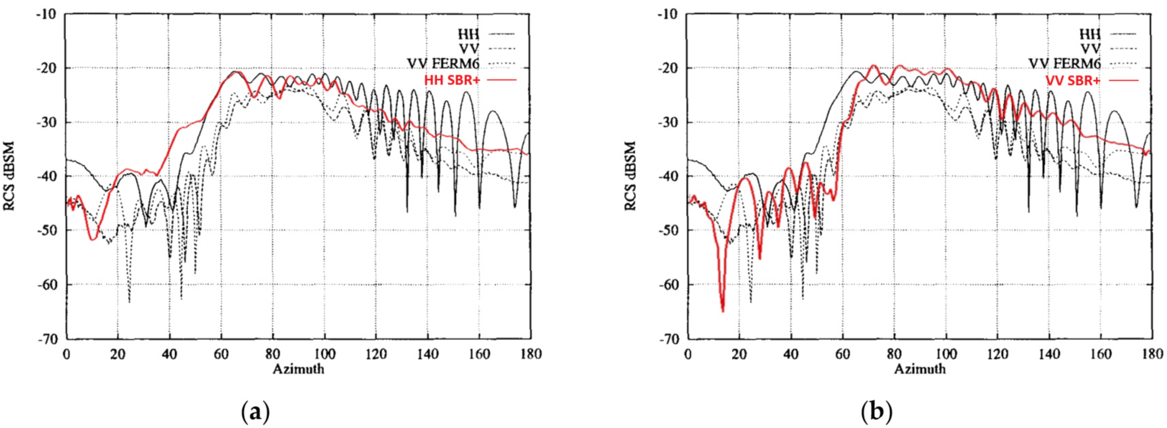
Figure 9 presents the comparison between the simulated and measured RCS of the NASA Almond model at 9.92 GHz [
29]. The results indicate that although discrepancies can be observed in both HH and VV polarizations, particularly in the azimuth range of 0–20°, the average values exhibit strong agreement. Moreover, beyond 60° azimuth, the simulated and measured results align more closely for both polarizations, providing further evidence of the robustness of the SBR+ method. It should also be noted that parameters such as ray density, the maximum number of bounces, PTD and uniform theory of diffraction (UTD) settings, and mesh resolution have an effect on the accuracy of the SBR+ simulations.
4.2. RCS Reduction
The RCS of a conducting cone can vary with increasing frequency according to the geometrical structure of the cone and the relationship of the wavelength to the cone dimensions. At low frequencies, when the wavelength is much larger than the dimensions of the cone, the RCS generally tends to increase with increasing frequency. At medium frequencies, it exhibits a more complex behaviour as the wavelength approaches the dimensions of the cone and the RCS may fluctuate due to resonance effects. At high frequencies, when the wavelength is much smaller than the dimensions of the cone, the RCS generally approaches a constant value depending on the geometrical properties of the cone. These variations can also be influenced by the surface properties and material structure of the cone.
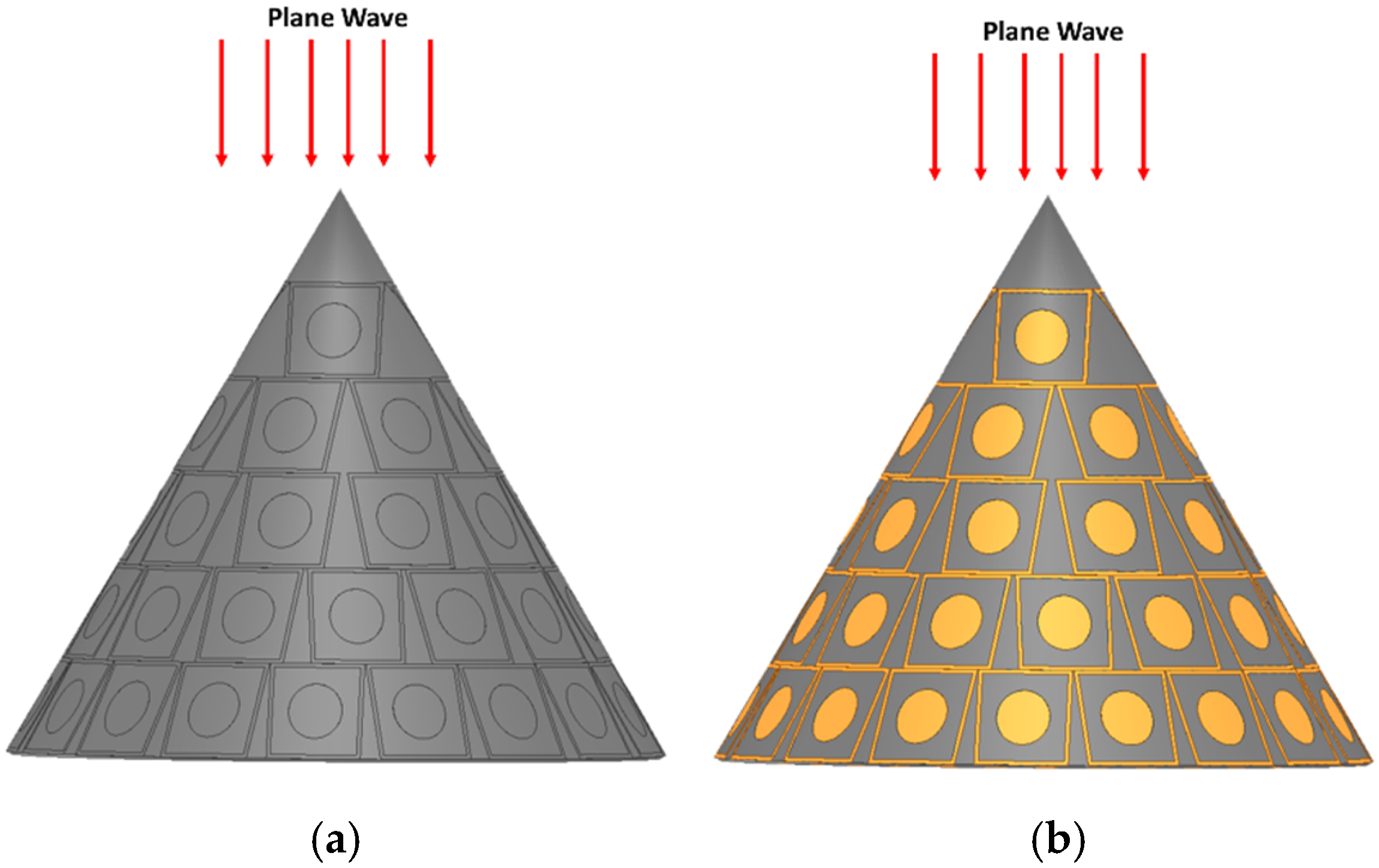
In this study, ANSYS HFSS software was used to perform monostatic RCS analyses of the conductive radome and the FSS-integrated radome. As shown in
Figure 10, the conducting radome and the FSS radome were excited by plane wave to simulate the monostatic RCS. Here, it is important to note that the unit cell simulations were performed in CST Studio Suite, which provides an efficient framework for periodic boundary and Floquet port analyses. The RCS computations and the validation using the NASA Almond model were conducted in ANSYS HFSS to take advantage of its advanced implementation of the SBR+ technique, which is particularly suitable for electrically large and conformal geometries. Although minor numerical discrepancies can exist between these two solvers, as also reported in the literature [
20], both CST and HFSS are based on full-wave electromagnetic formulations. Consistent frequency responses and scattering trends were observed in our simulations, confirming the reliability of the adopted analysis process.
Figure 11 presents a comparative analysis of the monostatic RCS performance of the conductive and FSS-based radomes across the frequency range of 2–14 GHz. Since the designed conical radome corresponds to a millimeter-scale structure, only a slight increase in the RCS of the conductive radome is observed up to the X-band frequencies, with no significant variation across the overall frequency range. In contrast, the RCS values of the FSS-integrated radome remain consistently lower than those of the conductive radome at all analyzed frequencies.
At approximately 10 GHz, the RCS of the FSS radome shows a noticeable increase, approaching that of the conductive radome. This behavior can be attributed to the resonant characteristics of the FSS, where the bandpass behavior allows part of the incident electromagnetic energy to be transmitted through the structure. Some of the transmitted energy interacts with the inner surface of the radome, resulting in a slight enhancement in backscattered energy. Outside the resonant region, the FSS behaves predominantly as a reflective surface, redirecting most of the scattered energy away from the backscattering direction, which leads to the observed RCS reduction.
Furthermore, the observed RCS behavior is consistent with the expected physical mechanisms of conformal FSS structures. The reduction in RCS outside the operating band reflects the ability of the FSS to suppress backscattering by redirecting non-specular Floquet components. Minor discrepancies near the cone tip may also arise from the inherent limitations of the SBR technique, which tends to be less accurate for sharply curved geometries due to edge diffraction effects.
Overall, these results confirm that the incorporation of the proposed bandpass FSS enables a notable reduction in the monostatic RCS of the conical radome. This highlights the potential of the proposed approach in optimizing electromagnetic transparency within the operational band while effectively suppressing unwanted scattering at out-of-band frequencies, thereby improving the stealth performance of radome systems.
5. Discussion
5.1. Dual Functionality
The results presented in this study demonstrate the effectiveness of integrating the proposed conformal-bandpass FSS into a conical radome for RCS reduction. Compared to a conventional conductive radome, the proposed FSS-based design consistently exhibits lower RCS values across a broad frequency range, with reductions exceeding several decibels at most frequencies. These findings emphasize the capability of the proposed structure to maintain electromagnetic transparency within the operational frequency band while effectively suppressing backscattering at out-of-band frequencies. This dual functionality also demonstrates its suitability for both radome performance and stealth enhancement.
5.2. Practical Design Considerations
In addition to its electromagnetic advantages, the proposed unit cell geometry offers significant practical benefits. Unlike many existing conformal FSS radome designs that rely on multilayered or highly complex geometries, this work employs a simpler and more manufacturable configuration. This approach not only facilitates large-scale production but also reduces cost and fabrication complexity, which are critical considerations for aerospace and defense applications. Thus, the study presented in this article is expected to contribute to the literature by proposing a balanced design approach that combines electromagnetic efficiency with manufacturability.
5.3. Limitations and Future Work
Despite these promising outcomes, it should be emphasized that the present work is entirely simulation-based. While advanced numerical techniques such as the SBR method provide reliable predictions, practical validation through fabrication and experimental measurements is essential for further verification. The absence of experimental data currently constitutes the main limitation of the study. As part of future work, efforts will focus on the fabrication of the proposed FSS radome and the experimental characterization of its transmission, reflection, and RCS properties. Such measurements will not only validate the simulation results but also reveal the impact of real-world factors such as fabrication tolerances, material inhomogeneities, and assembly imperfections.
Additionally, during the conformal mapping of the square FSS unit cells onto the conical surface, small triangular gaps naturally appeared between adjacent cells due to curvature. This effect was considered acceptable in the current stage since the square geometry offered fabrication simplicity and preserved the optimized electromagnetic response demonstrated in planar analysis. However, future studies may explore the implementation of alternative lattice configurations, such as triangular or hexagonal arrangements, to perform a comparative assessment of their electromagnetic and structural behaviors under conformal conditions. Such studies could provide additional insights into the geometric adaptability of conformal FSS structures.
Furthermore, the current RCS analysis considered only normal plane-wave incidence to establish a consistent comparison between the conductive and FSS-integrated radomes. While this provides valuable baseline insight, real-world radar scenarios often involve varying incident angles and polarization states. Therefore, future work will also include angular- and polarization-dependent RCS analyses to evaluate the scattering performance of the proposed conformal structure under more realistic electromagnetic conditions. In addition, the RCS behavior across different observation directions within the X-band will be examined to better capture the effects of bistatic scattering and angular redistribution of energy, which are highly relevant for radar stealth applications. This extension is expected to provide a more comprehensive understanding of the electromagnetic behavior and operational performance of the radome in realistic aerospace and defense applications.
The insights gained from these analyses will guide the forthcoming experimental validation phase and support the continued refinement of conformal FSS radome technologies, paving the way for their practical implementation in next-generation stealth systems.
6. Conclusions
This study proposes a simulation design for a conformal-bandpass FSS in radome applications within the 8–12 GHz frequency range. The proposed design was achieved by optimizing the geometry of the unit cell through electromagnetic simulations. When integrated into a conical radome configuration, the FSS was shown to significantly reduce the monostatic RCS compared to a conventional conductive radome. Furthermore, it was able to maintain acceptable transmission characteristics within the operational frequency band. These results confirm that the proposed conformal FSS radome design can satisfy the requirements of electromagnetic transparency and radar signature reduction. This highlights its potential as a promising approach to advanced radome development.
The simplicity and manufacturability of the proposed unit cell geometry make the design particularly attractive for real-world applications. Unlike multilayered or highly complex FSS configurations, the presented approach offers a cost-effective and scalable solution for aerospace and defense platforms, where both electromagnetic transparency and reduced radar visibility are critical.
The current work was limited to full-wave simulations. The next step will be to fabricate the designed FSS radome and experimentally characterize its transmission and RCS performance. Such measurements are expected to validate the simulation results and provide deeper insights into the effect of fabrication tolerances and material properties on the overall system performance.

