1. Introduction
Due to its low permeability, high plasticity, and ability to self-heal after damage, salt rock is considered an ideal geological medium for energy storage and nuclear waste disposal [
1,
2]. At present, nearly 100 underground salt rock storage facilities have been constructed and put into operation worldwide [
3].
Damage in salt rock primarily causes two issues: first, under long-term cyclic loads, it develops microcracks that compromise the stability and sealing of salt cavern gas storage facilities [
4,
5,
6], allowing gas to escape along fractures [
7,
8]; second, the further development of microcracks may result in through-going fractures, seriously threatening the safe operation of gas storage caverns [
9,
10]. For example, the collapses of the Stratton Ridge salt cavern in Texas in 1992 and the Yaggy salt cavern in Kansas in 2001 [
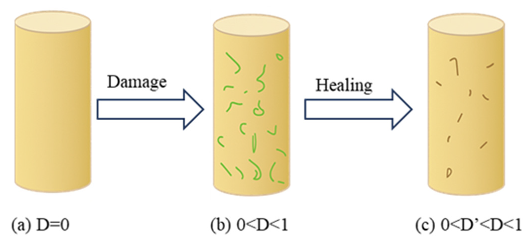
11]. However, the unique self-healing property of salt rock allows microcracks to heal under the action of pressure and other factors, thereby restoring its mechanical properties and enhancing the stability of the storage cavern (
Figure 1) [
12,
13].
Laboratory tests have shown that the self-healing of salt rock involves three mechanisms: mechanical closure, diffusion, and recrystallization [
14,
15]. Building on research into these self-healing mechanisms, numerous scholars have investigated the influencing factors of salt rock healing. Existing studies indicate that the healing of salt rock is mainly affected by physical factors such as moisture, temperature, confining pressure, initial fracture state, and mineral purity [
16,
17,
18,
19,
20,
21,
22]. Among them, Brodsky [
16,
17] demonstrated that the healing rate of salt rock is proportional to confining pressure and temperature, but inversely proportional to the degree of initial fractures. Chen et al. [
22] also conducted related research on the effect of humidity on salt rock healing, while [
15] through humidity cycling treatment, revealed that humidity cycles exert a positive influence on the healing of damaged zones in the salt cavern surrounding rock. Fuenkajorn et al. [
18] argued that impurities in salt rock significantly reduce the healing effect. These studies provide fundamental support for a deeper understanding of the healing mechanisms of salt rock.
Although laboratory experiments have revealed the self-healing mechanisms of salt rock and provided parameter support for engineering design, they are limited by sample size, loading method, and environmental conditions, and thus fail to fully reflect actual working conditions. As an important complement, numerical simulation enables systematic analysis of fracture evolution and mechanical response processes at the mesoscopic scale.
Among various numerical methods, the finite element method (FEM), owing to its well-established theoretical system and wide engineering applications, has become one of the primary approaches for numerical simulation of salt rock damage–healing. For instance, Fuenkajorn and Serata [
23] developed a numerical model based on FEM to evaluate the long-term stability of underground structures in brittle–ductile media and simulated the mechanical behavior of salt rock specimens in laboratory tests. Yang et al. [
24] used FEM to simulate the dissolution of salt rock in dynamic water. Ngo et al. [
2], based on fracture mechanics theory, adopted the extended finite element method to simulate the cracking process of rock salt caused by rapid cooling. Mahnken et al. [
25] proposed a coupled FEM strategy and a flow–solid phase strategy to study the deformation of rock salt under long-term stress together with the simultaneous occurrence of fluid seepage. Wu et al. [
26] established a Split Hopkinson Pressure Bar (SHPB) based on the coupling of FLAC3D and PFC3D. Subsequently, the fracture characteristics of shale specimens with different bedding tensile strengths were investigated. However, as FEM is based on the assumption of a continuous medium, it still faces limitations in dealing with problems such as discontinuous fracture propagation, microstructural damage, and reconstruction.
PFC(Particle Flow Code, 6.0 version), as a particle flow–based discrete element numerical simulation software, has gradually become an important tool for modeling the microscopic fracture behavior of salt rock, owing to its outstanding advantages in simulating discontinuous medium rupture, fracture initiation and propagation, and the dynamic transmission of contact forces between particles [
27]. Zhao et al. [
28] employed the particle flow method, combined with the Burgers model and the linear parallel bond contact model (LPB), to research the damage and failure of salt rock under creep–fatigue conditions. Li and Müller [
29,
30] proposed a three-dimensional grain-based model constructed through Voronoi tessellation, and validated its effectiveness by comparing laboratory experiments with numerical simulations. Li et al. [
31] constructed a thermo-mechanical coupling model to investigate the influence of temperature on the mechanical properties of salt rock; Liang et al. [
32] developed a multiscale polycrystalline salt rock model to analyze the effect of particle size distribution on macroscopic mechanical responses; Gutiérrez-Ch et al. [
33] improved the simulation of rock shear creep by employing the DEM + RPT method.
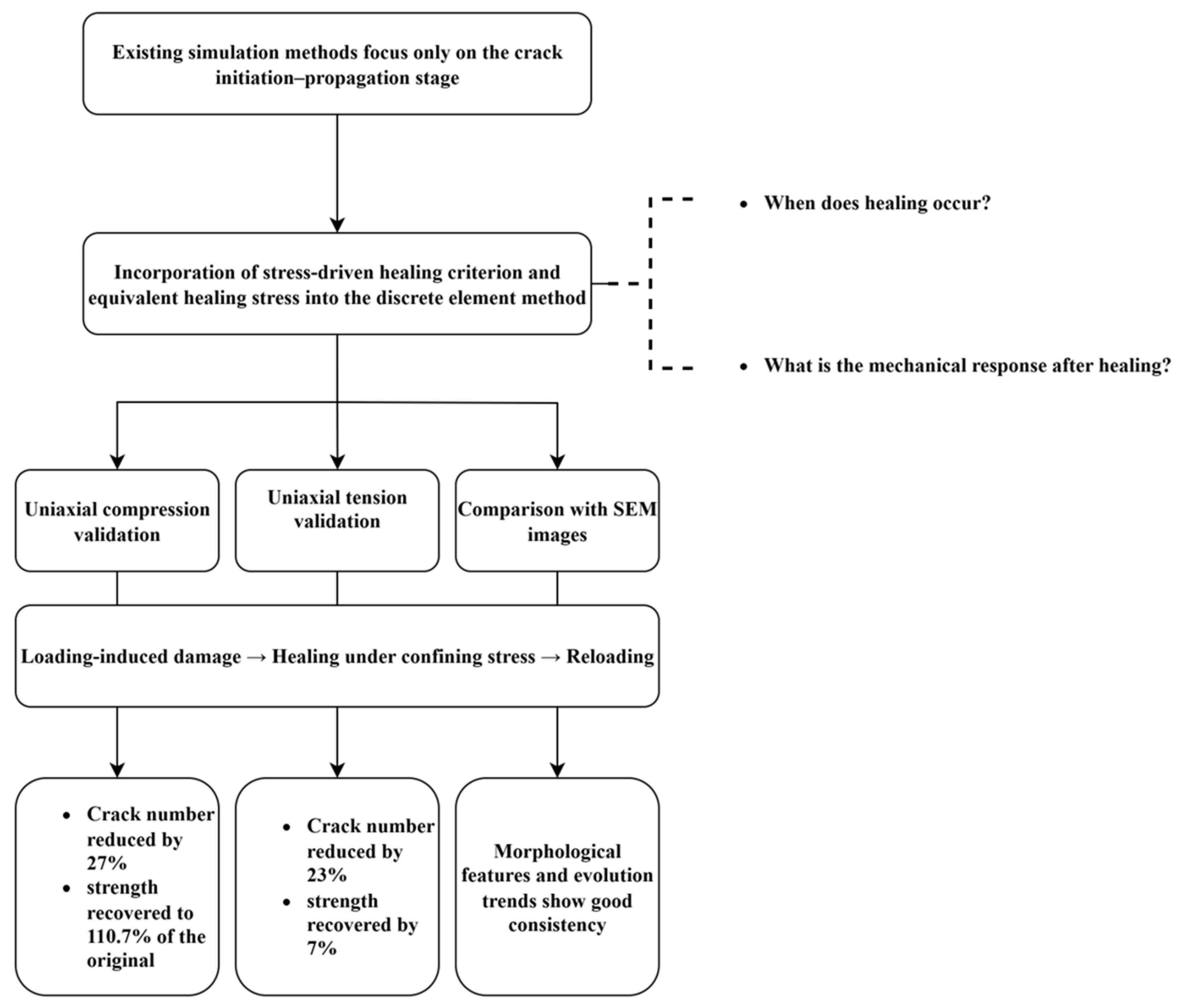
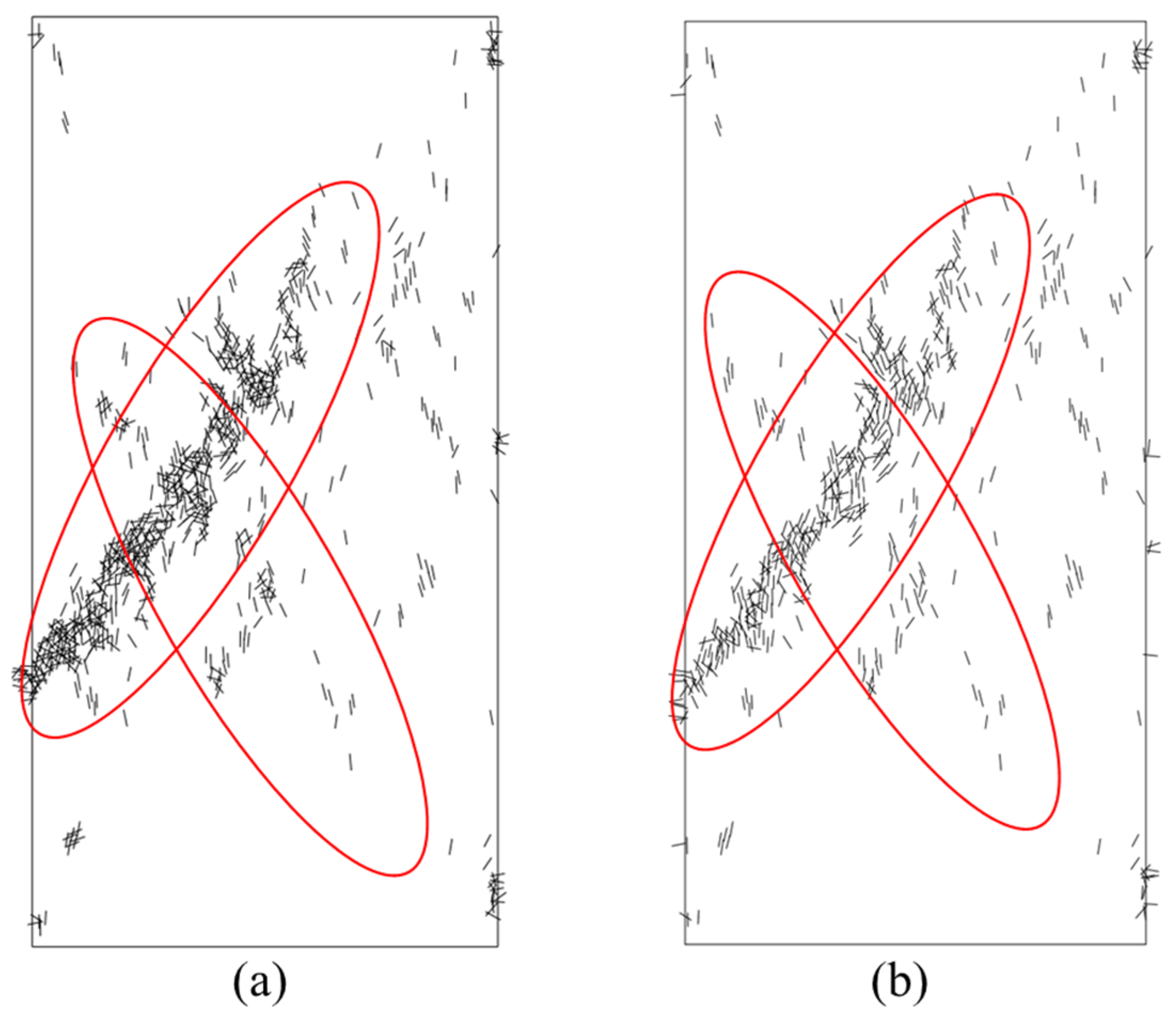
These studies have achieved significant progress in revealing the meso-scale damage evolution of salt rock. However, most of them remain focused on the stages of crack initiation and propagation (
Figure 2), while lacking criteria for processes such as crack closure, contact bond recovery, and microstructural reconstruction, as well as the post-healing mechanical response. This limits the application of discrete element numerical simulation methods in studying salt rock “damage–healing”.
To address this critical gap, this study successfully constructs a damage–healing numerical model for salt rock within the Discrete Element Particle Flow Code (PFC2D) framework by introducing the Hou/Lux healing criterion and the MDCF equivalent stress mechanism. This model not only clearly reveals the mechanical driving mechanism of microcrack closure and achieves the unification of mesoscopic damage evolution and macroscopic mechanical response but also provides strong theoretical support for optimizing gas storage cavern operational parameters (e.g., internal pressure control, injection–production rate).
2. DEM for Damage Self-Healing
This section proposes a PFC2D-based discrete element method for simulating the entire process of salt rock fracture “damage–healing.” In terms of physical mechanisms, salt rock healing is primarily manifested as crack closure, interface re-contact, and structural densification; in terms of numerical implementation, the traditional parallel bond model (PBM) is extended by introducing the Hou/Lux healing criterion to describe stress-driven crack closure, incorporating the MDCF equivalent stress mechanism to characterize the microscopic mechanical response after healing, and embedding the healing logic through FISH programming to enable the dynamic reconstruction of contact bonds between particles. In this way, the physical processes of closure and recrystallization are numerically represented as a reduction in crack number, restoration of contact chains, and recovery of mechanical properties, thereby effectively reproducing the structural recovery behavior of salt rock after failure.
To enhance informativeness, the model records not only the macroscopic stress–strain response, but also the microscopic indicators such as crack initiation, propagation, and closure events. Furthermore, the proposed healing criterion is formulated at the micromechanical level, ensuring that the damage–healing process is represented as a kinetic model consistent with the discrete element framework.
2.1. Damage–Healing Method
2.1.1. Micromechanical Criteria for Crack Initiation and Propagation
In this study, the onset of microcracking was modeled using the standard parallel bond model (PBM) failure criteria implemented in PFC. Each parallel bond is treated as a finite-sized cementitious contact, capable of transmitting both forces and moments until its strength limits are exceeded.
Tensile failure occurs when the average normal stress across the bond cross-section
, exceeds the tensile strength
σcShear failure is evaluated if tensile breakage does not occur. The shear strength is given by:
where
c is the bond cohesion,
ϕ the internal friction angle, and σ =
n/A the average normal stress on the bond cross-section. If the average shear stress
exceeds this strength,
then the bond fails in shear.
Once a bond has broken, a bond break event is triggered, and the corresponding contact is recorded as a microcrack initiation site. The accumulation and coalescence of such broken bonds leads to the formation of localized crack bands, thereby linking the particle-scale bond mechanics to emergent macrocrack propagation.
The preceding damage stage establishes the primary condition for the salt rock self-healing process: healing can only occur when bonds are broken, creating repairable spaces and interfaces. Consequently, the position of the cracks, the contact state of the particles, and the micro-stress distribution (all determined by the damage stage) collectively constitute the prerequisites for the healing action. Thus, this model uses the post-damage microscopic state as the input for the healing stage. The following sections will detail the kinetic criteria for salt rock healing, specifically under which stress-driven conditions these broken contact bonds can be reconstructed and their mechanical properties restored.
2.1.2. Damage–Healing Criterion
Hou/Lux Model [
34,
35] combines the damage theory of continuum mechanics and integrates the processes of damage and healing in salt rock deformation in a phenomenological manner. In this model, the volumetric shrinkage induced by healing is expressed as:
where
εvol is the dilatancy strain,
Qh is the flow potential function,
F* is the stress reference value, here taken as
F*
= 1 Mpa [
34],
Fh is the plastic potential function induced by damage healing,
σij is the stress tensor, and
a11,
a12,
a13 are model parameters.
The flow potential function
Fh determines whether the strain rate induced by healing is activated. Therefore, it is considered as the criterion of damage healing in PFC, expressed as:
where
σ3 is the minimum principal stress,
a5,
a6 are model parameters, here
a5 = 0.055 Mpa
−1,
a6 = 67.0 MPa [
34], and
σv is the von Mises stress. When
Fh > 0, healing occurs; when
Fh < 0, healing does not occur.
Since PFC is a discrete particle system, the continuous stress state of the particle assembly must be redefined. The stress state of the particle system is expressed using the Representative Elementary Volume (REV) method [
36].
where
V is the size of the REV,
is the set of contacts within the REV,
is the contact force, and
is the branch vector. This method is implemented in PFC through the measurement circle, with the stress calculated as:
where
is the average stress,
is the contact force vector,
is the branch vector connecting the centroids of the two contacting particles, and
is the number of contacts within the measurement region.
2.1.3. Healing Equivalent Stress
Chan et al. [
37], in the Multimechanism Deformation Coupled Fracture (MDCF) model, proposed a formula for the healing equivalent stress:
where
I1 is the first invariant of stress, and
x10 is the equivalent healing parameter.
To apply the healing equivalent stress from the MDCF model in PFC simulations, the macroscopic stress state must be linked with the microscopic contact forces. Assuming that two spheres interact microscopically through a circular flat contact area with radius
, the normal bond force after healing is expressed as follows:
where
is the area of the contact region, and in the two-dimensional case,
. Substituting into Equation (5) yields:
Consequently, the total parallel bond force after healing is:
where
ks is the parallel bond shear stiffness, and
δs is the shear displacement.
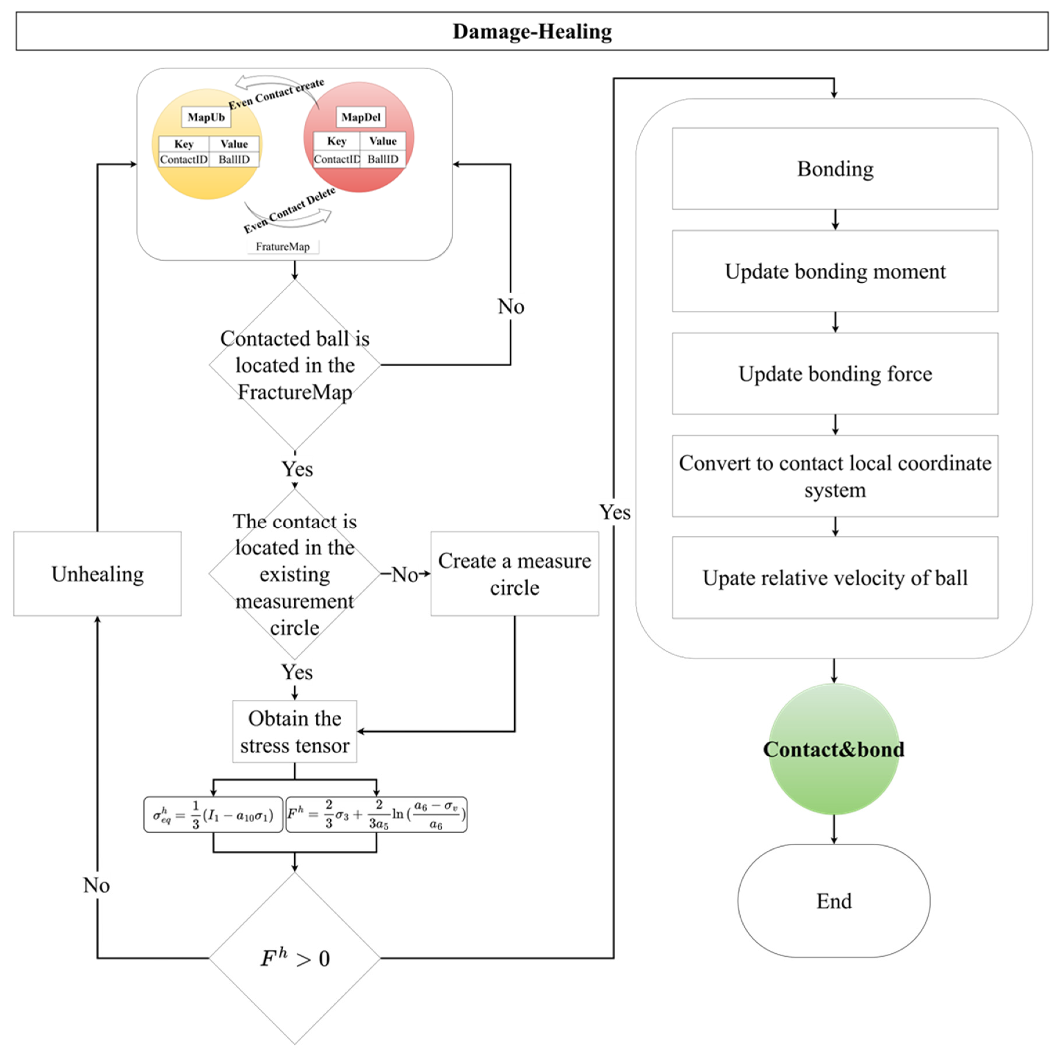
The healing process is illustrated in
Figure 3.
2.2. Damage–Healing Simulation Scheme
To validate the effectiveness of the proposed simulation method, numerical tests of salt rock damage–healing were conducted under different damage conditions, including uniaxial compression and uniaxial tension. The specific steps are as follows:
(1) A rectangular specimen with dimensions consistent with the laboratory tests, 50 × 100 mm, was established. The maximum-to-minimum particle radius ratio was set to 1.3 [
38], with particle radii ranging from 0.6 to 0.84 mm. Resulting in a final model containing 7863 particles of varying sizes (
Figure 4).
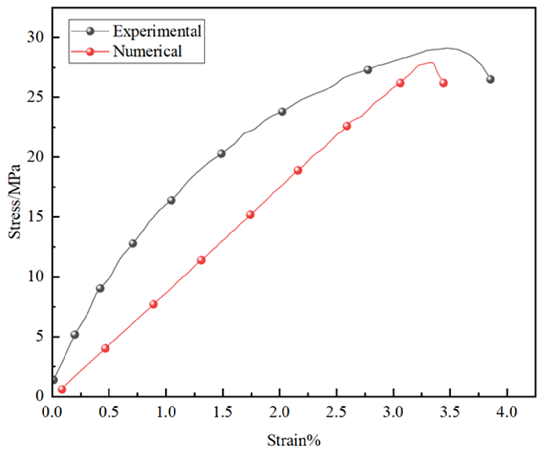
The contact model and meso-scale parameters were assigned: based on the parallel bond contact model and the experimental studies of Li and Zhao [
39,
40], the parameters for different specimens were calibrated using a trial-and-error method (
Figure 5), as shown in
Table 1:
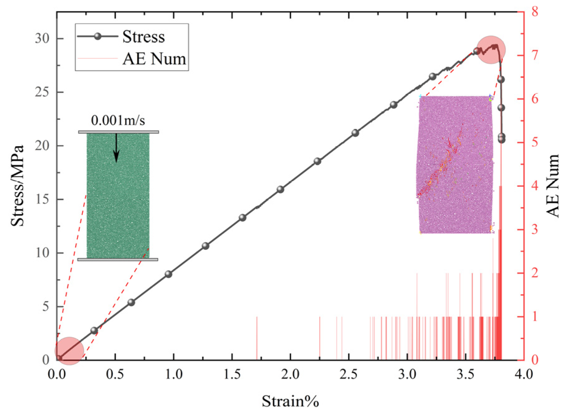
(2) Damage Loading: During uniaxial compression, displacement-controlled loading was applied at a rate of 0.001 m/s, and the specimen was loaded beyond the peak stress to induce additional damage (
Figure 6).
Previous studies have shown that under cyclic loading, a strong correspondence exists between fracture evolution and acoustic emission (AE) activity in fractured rocks [
41].Analogous to AE experiments, the present study uses the change in the number of microcracks (the number of broken bonds, ct) within a certain time interval to represent the AE ringing count
in the specimen [
42]:
At the initial stage of loading, the number of events is relatively small; as the stress increases and microcracks initiate and propagate, the number of AE events increases significantly. This is particularly evident near the peak strength and during the subsequent stress drop phase, where AE events increase sharply (
Figure 6).
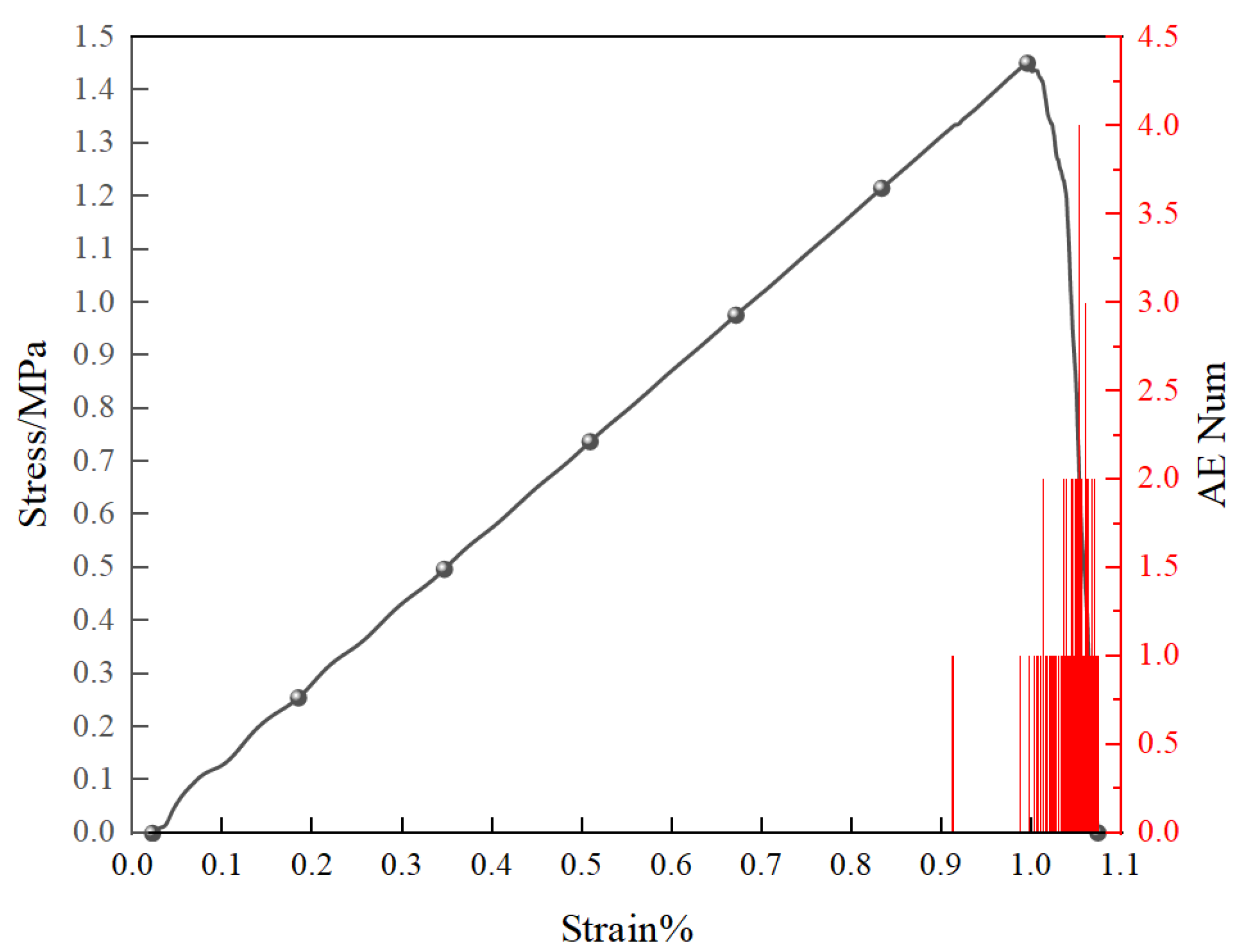
During uniaxial tension, flexible loading was applied by imposing a constant velocity on the particles at the upper and lower boundaries of the specimen. The loading rate was set to 0.003 m/s, and the specimen was loaded until failure (i.e., tensile strength reduced to zero) (
Figure 7 and
Figure 8).
(3) Damage-Healing: Based on the initially damaged state, healing was performed according to the methods described in
Section 2.1.2 and
Section 2.1.3. This study focuses on the differences in mechanical behavior before and after stress-driven healing, and the following criteria were proposed for terminating the healing process:
- ①
No significant change in volumetric strain over 1 × 10⁵ time steps, i.e.,
- ②
No change in the number of cracks over 1 × 10⁵ time steps;
- ③
The ratio of the average unbalanced force in the particle system is less than 1 × 10⁻⁴
(4) Secondary Loading: For the healed specimens, secondary loading was applied under the same conditions as in Step (2) to investigate the differences in the mechanical behavior of salt rock before and after healing.
3. Results and Validation
3.1. Uniaxial Compression
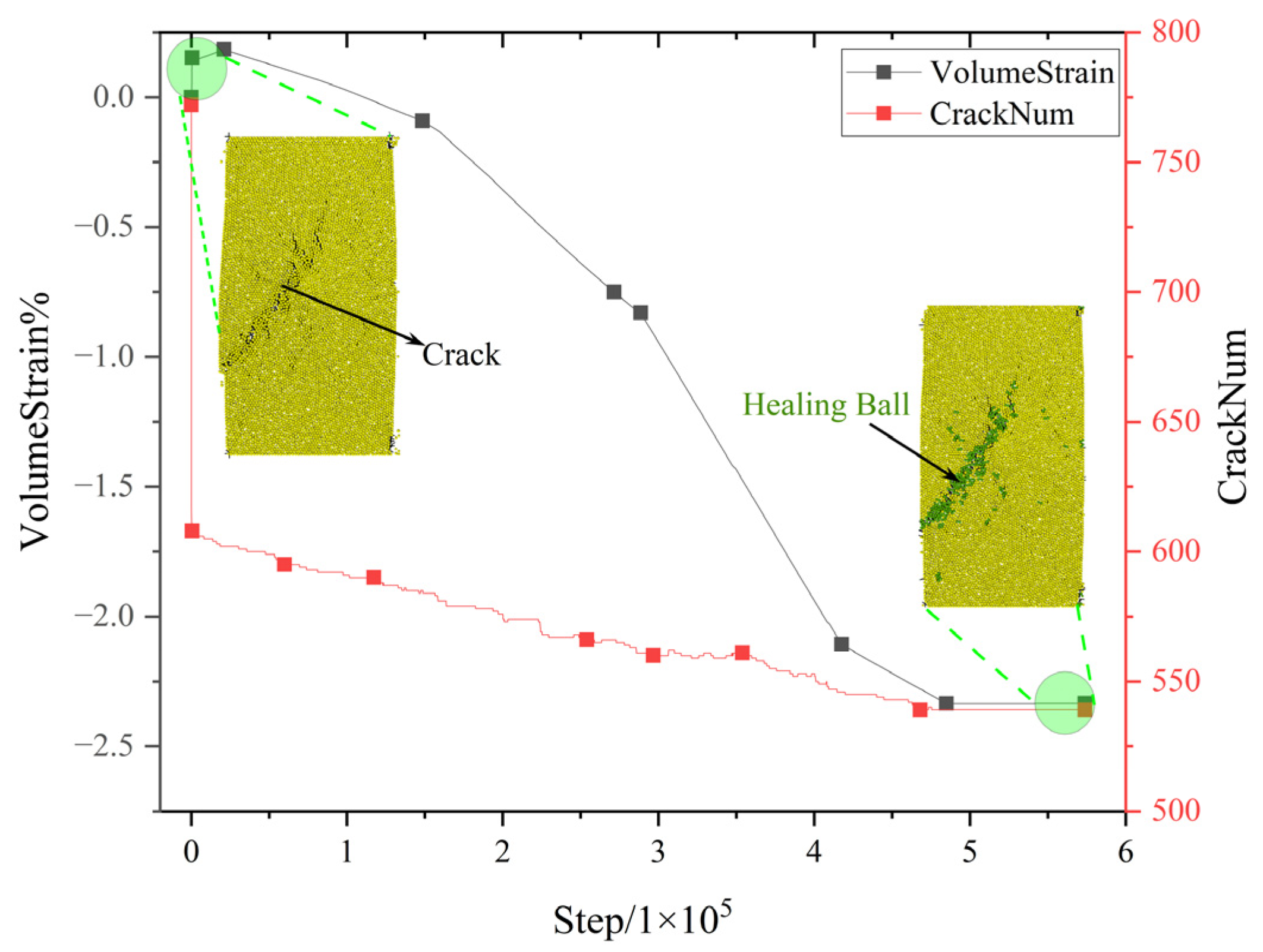
As shown in
Figure 9, during the healing process, the number of cracks decreased continuously from approximately 750 to 550, indicating that part of the damaged region had closed through re-bonding. At the same time, the volumetric strain continuously decreased and gradually stabilized, reflecting the densification effect of the particle system during the healing stage. The coordinated evolution of cracks and strain suggests that the healing process involves not only local structural reconstruction but also macroscopic volumetric changes.
It is noteworthy that the number of cracks decreased rapidly at the initial stage of healing, whereas the change in volumetric strain was relatively delayed, exhibiting an asynchronous evolution characterized by “cracks close first, structure densifies later.” This mechanism can be attributed to two stages: in the first stage, once the healing criteria between particles are satisfied, broken bonds are rapidly reconstructed, resulting in a reduction in crack number; in the second stage, as mechanical connections are restored, stress is redistributed within the system, triggering particle rearrangement and volumetric compression.
From a simulation perspective, crack closure manifests as abrupt changes in discrete variables, whereas volumetric strain results from the gradual evolution of the geometric structure, with differing response rates. This temporal relationship not only reflects the mesoscopic realism of the model but also reveals the intrinsic linkage between microstructural recovery and macroscopic deformation during the healing of salt rock.
In terms of the failure pattern, cracks predominantly developed along the shear direction, forming through-going failure zones, and healing primarily occurred in these regions (
Figure 9 and
Figure 10). After healing, the crack density was significantly reduced, the boundaries of the failure zones became less distinct, and many cracks were transformed into isolated, discontinuous microcracks, indicating that the continuity of the failure zones was substantially weakened.
From the perspective of macroscopic mechanical performance (
Figure 11), the strength of the healed specimen reached approximately 110.7% of the original strength, while the elastic modulus decreased by 15%. This indicates that both the strength and plasticity of the specimen were enhanced to varying degrees after healing, which is consistent with experimental observations [
40]. These results demonstrate that the proposed method is feasible and effective for simulating damage–healing behavior in salt rock.
3.2. Uniaxial Tension
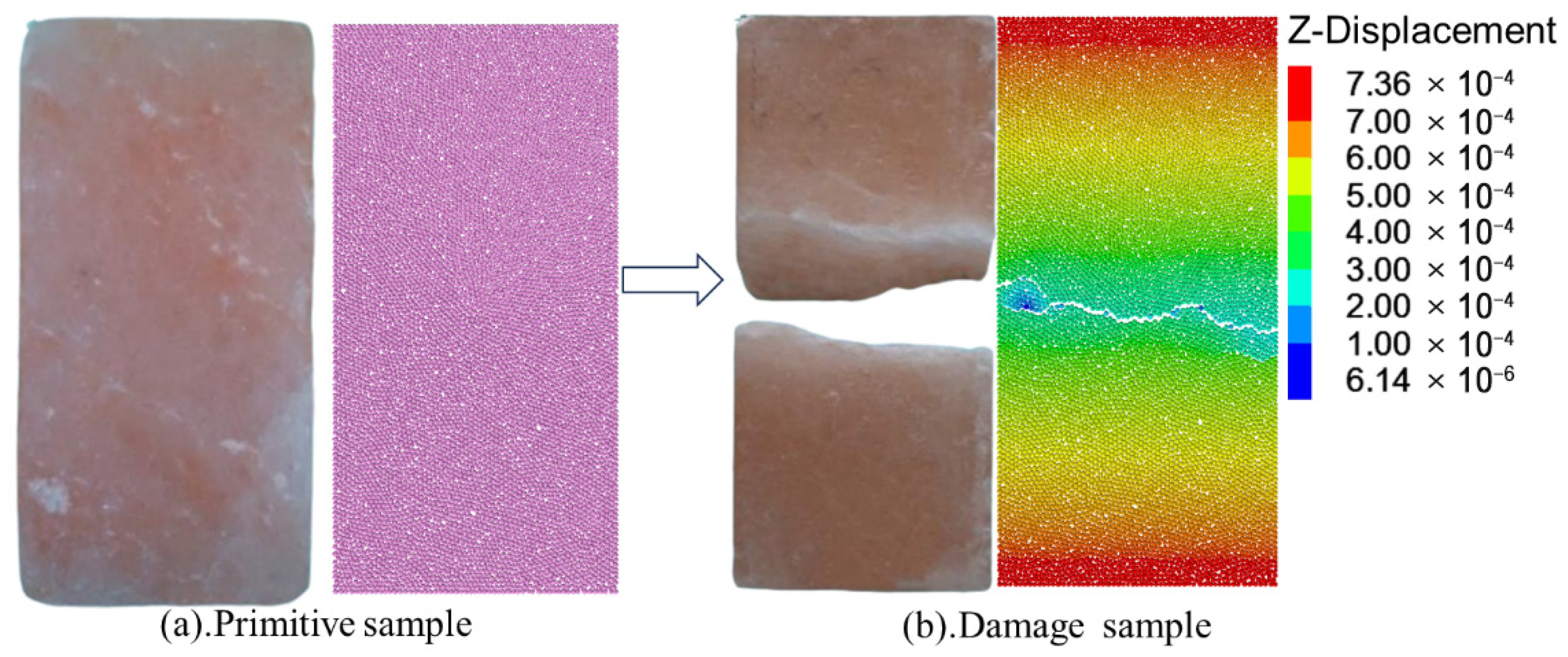
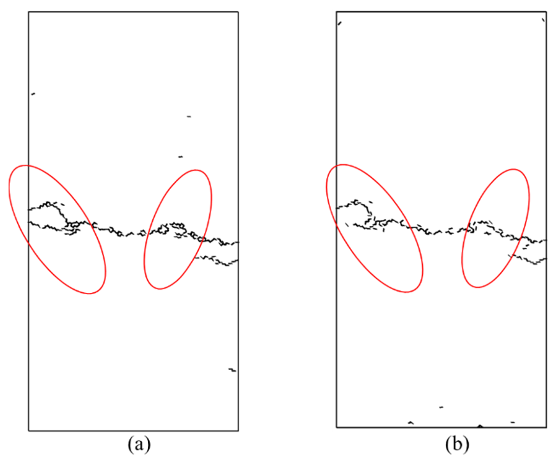
Under uniaxial tension, the specimen rapidly fractured due to tensile stress concentration between particles, with cracks propagating vertically to form a primary fracture zone (
Figure 12a). At this stage, all bonds were broken, and the model’s tensile strength dropped to zero, representing complete failure. After initial damage, the total number of cracks in the specimen was 185; following the healing treatment, this number decreased to 142, with a significant reduction in crack density and the fracture surfaces tending toward discontinuity (
Figure 12b and
Figure 13). The corresponding volumetric strain exhibited approximately 0.35% contraction (
Figure 14), indicating that crack closure induced local densification between particles.
After the healing process, the specimen was subjected to secondary tensile loading. The maximum stress reached approximately 7% of that in the intact specimen. Although the strength recovery was limited, it was noticeably higher than the damage-limit state, indicating that the healing process partially reconstructed the mechanical connection chains in the cracked zone and achieved partial re-bonding.
Overall, under uniaxial tension, the healing process was primarily characterized by a reduction in the number of cracks, volumetric densification, and partial recovery of strength. Compared with compressive loading, tension-induced failure is more instantaneous and through-going, resulting in crack geometries that are more difficult to close, thereby limiting the degree of healing.
3.3. Microscopic Comparison Between Simulation and SEM Images
To verify the microstructural rationality of the PFC damage–healing model constructed in this study, the numerical simulation results were compared with existing SEM images of salt rock [
39].
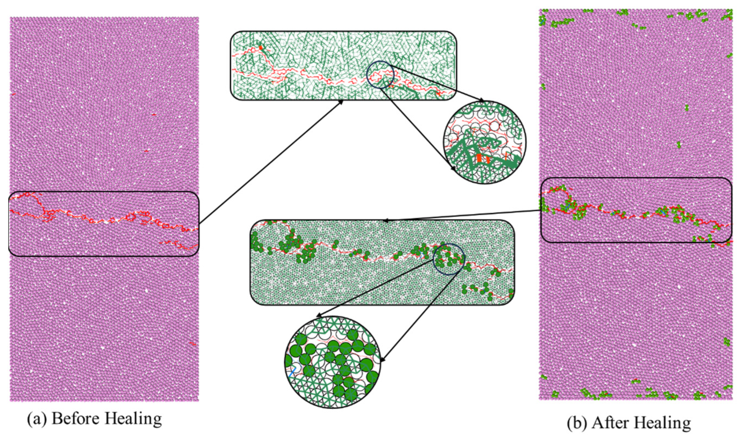
As shown in
Figure 15, in the PFC simulations, damage-induced cracks formed open fractures along the shear bands. After healing, some particles re-established contacts, forming a bond network analogous to “crystal bridges” [
43,
44], exhibiting a clear tendency for local closure.
Previous SEM analyses of healed salt rock specimens [
39] have similarly revealed crystal re-deposition and re-bonding phenomena at crack interfaces, confirming that the model reasonably reproduces the key morphological characteristics of the damage–healing process.
The structural evolution paths show a strong agreement between the simulation and experimental observations reported in the literature: cracks evolve from through-going → reconnected → locally closed, with healing preferentially occurring in stress-concentrated regions. Although the underlying micro-mechanisms differ—manifesting as force-chain reconstruction of the bonded network in the simulation versus crystal re-contact and growth observed in SEM studies—the simulated localized bridging structures display qualitative consistency in morphology and evolution trends with the experimentally observed crystal bridges.
Overall, the numerical model successfully captures the crack closure and structural recovery of salt rock from damage to healing, and the morphological evolution demonstrates the physical feasibility of the proposed method at the microstructural level.
4. Conclusions
Based on PFC2D, this study proposed a discrete element model capable of simulating the full process of damage–healing in salt rock. By incorporating the Huo/Lux criterion and the MDCF equivalent stress mechanism, the model enables continuous simulation of crack initiation, propagation, and closure. The main conclusions are as follows:
(1) Effectiveness of stress-driven healing: The proposed healing criterion effectively triggers crack closure and structural densification. In uniaxial compression and tension, the number of cracks decreased by approximately 27% and 23%, respectively, with a noticeable improvement in mechanical performance.
(2) Consistency between microscopic and macroscopic responses: The reconstruction of particle contact chains during healing closely corresponds to the crystal-bridge phenomena observed in experiments. After compressive healing, the recovered strength reached 110.7% of the original value, while after tensile healing, it reached about 7%, confirming the model’s capability to reproduce realistic macroscopic mechanical responses.
(3) Temporal characteristics of healing: The rapid decrease in crack number precedes the change in volumetric strain, indicating an evolution characterized by “structural closure first, macroscopic densification later”.
(4) Engineering relevance: The proposed model can capture the closure and strength recovery of salt rock fractures at the micromechanical scale. It provides a useful reference and theoretical basis for evaluating the sealing performance and structural stability of underground salt caverns used for gas or energy storage.
In summary, the developed model serves as an effective numerical tool for quantitatively characterizing the healing behavior of salt rock and for assessing the long-term sealing performance and mechanical integrity of salt cavern repositories.
5. Discussion
This study presents a preliminary yet comprehensive investigation of the dynamic damage–healing process in salt rock. AE was only considered during the damage stage, where simulated bond breakage trends were compared with typical AE patterns from the literature; the healing stage did not incorporate AE effects, and quantitative validation will be performed in future experiments.
The current work focused on a single loading–damage–healing cycle to verify the model’s fundamental feasibility. Future research will extend to multi-cycle and multi-condition simulations (e.g., varying confining pressure, temperature, and salt rock types) to evaluate long-term sealing performance and improve model generality.
Several idealizations remain. The simulation time steps do not correspond to real healing durations, and the stress-driven healing criterion does not explicitly include micro-environmental factors such as humidity, temperature, or interfacial curvature. In addition, key empirical parameters (e.g., a5, a6, x10) were taken from previous studies without DEM-specific sensitivity analysis. Crystallite size and mineral phase verification were not performed, and future work will incorporate XRD and thermo-mechanical coupling to enhance physical realism.
The proposed DEM framework will be further developed to include chemo–thermo–mechanical coupling and adaptive bond-healing algorithms to capture time-dependent evolution under cyclic stress. Integrating AE monitoring and CT-based microstructural imaging with simulation will enable more quantitative assessment of damage–healing mechanisms and long-term stability in underground energy storage and nuclear waste disposal.
