1. Introduction
Despite substantial funds from the European Union spent over the past twenty years on Polish road infrastructure, a significant portion of Poland’s bridge stock remains relatively old. It requires regular maintenance to guarantee adequate structural safety and serviceability. Structural safety is a key assessment parameter for existing bridges, guiding decisions on their continued use. Bridges built after World War II, during the reconstruction of war-damaged transport infrastructure, are now especially approaching the end of their service life. Efficient and reliable safety assessments are crucial for maintaining and managing the bridge stock. The condition of bridges directly affects traffic safety and transportation costs, which tend to decline over time due to physical damage such as corrosion, fatigue, overloading, or accidental impacts. Meanwhile, increasing traffic volumes necessitate upgrading the load-bearing capacity of existing bridges. To prevent the high costs of repairs, strengthening, or replacements, accurate assessments of bridge safety are becoming increasingly important worldwide [
1,
2,
3,
4,
5,
6]. Road authorities can make informed maintenance decisions and implement effective measures based on structural safety evaluations. Hence, there is a need for a systematic, cost-effective, quick, and precise method for assessing bridge safety to support effective management.
A key part of bridge management is assessing the safety of bridge structures. In simple terms, a bridge is considered safe if its load-bearing capacity exceeds the traffic load it carries. It can be regarded as safe when there is a sufficiently low chance that the traffic load will exceed its capacity. Extensive research has been conducted on methods to evaluate the structural safety of bridges and their associated uncertainties, ranging from basic approaches such as performance observation and design standards to more advanced techniques, including the analytical hierarchy process (AHP), fuzzy assessment, and neural networks. Recent assessment methods were briefly described, with their characteristics summarised and compared, by Lu et al. [
7] and Ferrara et al. [
8]. Comparing various bridge safety assessment methods shows both similarities and differences. For instance, the design standard method has a solid theoretical foundation and has been widely used in Poland until now [
8,
9,
10,
11,
12]. However, notable differences exist between design standards and assessment, especially in terms of information availability and updating, structural condition, reliability requirements, verification procedures, and decision options. These differences, briefly outlined in the contribution [
13], can often lead to a high level of conservatism when applying design standards for assessment. Typically, bridge safety assessments are based on calculation methods, where inspection findings on local damages, supported by non-destructive testing (NDT), are used to develop a realistic numerical model for finite element analysis (FEA). In a standard assessment process, condition surveys, material testing, and NDT provide valuable data for calibrating models, which in turn leads to a comprehensive structural analysis [
14,
15,
16,
17]. A combined, rational approach to these steps enables the detection, characterisation, and quantification of useful reserves in load-carrying capacity or the identification of the weakest structural points. Nonetheless, a calculation-based analysis begins with a deterministic calculation. A more advanced method becomes necessary if the structural safety standards are not met. Probabilistic methods are among such options [
18,
19,
20,
21]. Using a probabilistic approach involves an analysis tailored to the specific bridge, incorporating information on load and material property variations into the calculations. This method is well-suited for evaluating the structural safety of existing bridges.
The field-loading test method is the most direct and reliable approach for assessing bridge structural safety [
22,
23,
24,
25,
26]. Strain data obtained from static load testing of the bridge, together with modal information identified from the measured acceleration responses under operational traffic, are used simultaneously to update the numerical bridge model’s material properties and dynamic characteristics. Based on this revised model, the load-bearing capacity is calculated to evaluate the bridge’s performance under the current design traffic loading specified in various national guidelines or standards. However, the field-loading test method’s cost is relatively high, and the technique is not very widespread. Additionally, it may disrupt regular traffic, limiting its frequent application on highway bridges. It may also cause severe structural damage, particularly for existing bridges that lack essential original data. Another approach is to implement the structural health monitoring (SHM) system [
27,
28,
29,
30] on a bridge. Through monitoring and evaluating the structure’s condition, early warning signals are issued in cases of extreme climate conditions, severe traffic, or operational issues. This provides the basis and guidance for maintenance and management decisions. However, due to its high cost, SHM is mainly used for critical bridges and is rarely applied to small and medium-span bridges. To lower the costs of SHM in such cases, Jamali et al. [
31] suggest a multi-level assessment procedure for evaluating the load-bearing capacity of existing bridges, combining SHM techniques, advanced nonlinear analysis, and probabilistic approaches to address safety effectively. Recently, Ko et al. [
32] proposed a framework for assessing bridge structural safety using AI technology. This method allows evaluation of bridges with limited information, such as missing design documents, and does not require field tests. The framework relies on computational design strength and includes procedures for calculating calibration factors to reflect current conditions. Meanwhile, Liu & Zhang [
33] have developed a deep learning-based method to model bridge condition ratings using selected data from the National Bridge Inventory (NBI) database. This research aims to develop a data-driven approach that predicts the future conditions of highway bridge components based on archival inspection data, trained using an online-accessible NBI dataset.
Over the past twenty years, extensive research efforts have been undertaken worldwide to develop new assessment methods for existing bridges. The primary outcomes of this research are recent standards and manuals for existing bridges approved for use in the USA [
34], Canada [
35], China [
36], Italy [
37], Switzerland [
38], and the UK [
39]. There are also two international standards [
40,
41]. For a review and discussion of most of these standards, guidelines, and their frameworks, see [
42,
43]. These various national standards and guidelines particularly include key elements such as: (a) the possibility of directly applying probability-based methods, (b) the inclusion of structural system redundancy and robustness criteria, (c) the use of site-specific live loads and dynamic amplification factors, (d) the integration of field measurements and diagnostic test data, and (e) the consideration of proof load testing. Wisniewski et al. [
42] review how these key elements are addressed in existing assessment standards and suggest possible improvements. Allaix & Bigaj-van Vliet [
43] recommend amending Eurocode design rules for assessment situations, including the use of measured strengths and imperfections in calculations. Actions and their combination formats are also examined, with recommendations for adjustments to these aspects in bridge assessments. Ultimately, an overall evaluation of the scope of work needed to develop an assessment suite based on Eurocodes is presented. However, the new Eurocode prEN 1990-2 [
44] for assessment only establishes principles for specific reliability aspects. The consistent application of these general assessment rules in practice requires further assumptions or even case-specific developments. Therefore, practical applications are essential for identifying relevant issues in the future development of assessment methods and standards. This paper describes a new national method for the structural safety assessment of existing bridges that combines condition surveys, material testing, NDT, FE analysis, and Eurocodes’ calculation-based verification of ULS/SLS. The new method is the national implementation of the provisions of the new Eurocode prEN 1990-2 [
44], to be published on 30 January 2026, which extends the basis of structural design for new structures, as specified in standard EN 1990 [
45], to existing structures. The assessment framework is presented within the context of a case study involving a steel road bridge that has been in service for half a century. In the 1960s, a unique and modern thin-walled steel shell superstructure for highway bridges was designed and implemented for several road bridges in Poland. The fully welded superstructure consisted of a thin-walled external shell in a basket curve shape, stiffened with longitudinal trapezoidal ribs, and internal longitudinal and transverse trusses that stiffened the shell and ensured its overall stability. However, the superstructure has several structural and technological weaknesses that, in a short time, have led to severe structural damage, as observed in these bridges just a few years after service (e.g., weld cracks, local buckling, etc.). The national framework for the structural safety assessment, as applied to the bridge in question, is presented in the article. The research work confirmed, on the one hand, the need for quick maintenance decisions regarding other bridges of this type, and on the other hand, the usefulness of the new framework for assessing the structural safety of existing road bridges.
2. The National Framework for Structural Safety Assessment of Existing Road Bridges
A common issue in bridge management in Poland is determining the structural safety of existing, deteriorated bridges and their actual load-bearing capacity. It is crucial to make timely decisions on whether to continue, limit, or stop traffic operations, as this is vital for effective maintenance and management of bridges. However, Poland has lacked a consistent methodology for assessing the structural safety of road bridges. Consequently, developing a simple, fast, cost-effective, and reliable method to evaluate the safety of existing bridges, especially those that are damaged or deteriorated, has become increasingly important and urgent.
The origins of the Polish system for assessing the technical condition of road bridges date back to 1985, when the Act on Public Roads was enacted. This Act outlines the responsibilities of the road authority, including conducting periodic inspections of the technical state of road bridges. Following Poland’s political transformation, a new “Construction Law Act” came into force in 1994, which mandated and clarified the road authority’s obligation to carry out regular inspections, primarily to assess the technical condition of bridges. However, neither Act provided detailed rules for how these inspections should be performed. It was not until the 2004 regulation by the Minister of Infrastructure that the fundamental requirements regarding the scope and criteria for assessing the technical condition of key components and the entire bridge were defined.
Based on the regulation of the Minister of Infrastructure, the Polish national road authority, the General Directorate for National Roads and Motorways (GDDKiA), commissioned Rzeszów University of Technology to develop an instruction for conducting road bridge inspections, which came into force in 2005 [
46]. The instruction introduced a comprehensive inspection system for road bridges managed by GDDKiA, including current inspections, basic inspections, extended inspections, detailed inspections, and expert assessments. It also outlined, among other things, the frequency, purpose, methods, and documentation procedures for these inspections. To standardise the process of assessing road bridges by different bridge inspectors, in 2008, GDDKiA implemented rules for using a scale to rate the technical condition and suitability for continued use of road bridges, which were also developed by the Rzeszów University of Technology. The document provides guidelines and examples that, considering the inspector’s knowledge and experience, should be followed when assessing individual elements of road bridges during inspections (basic, extended, and detailed). The authors of both primary documents, which contain the Polish system for evaluating the technical condition of road bridges (instructions and rules), revised them in 2011 and 2020, respectively.
The system for assessing the technical condition of road bridges, which remains in use in Poland today, is based on a six-point scale aligned with the criteria in
Table 1 [
46]. Elements of a road bridge evaluated under these criteria include, in particular: main girders, deck slab, cables and their anchorages, expansion joints, road and pavement surfaces, drainage system, kerbs, railings, protective barriers, cornices, abutments and pillars, bearings, embankments and slopes of approach roads, riverbed and underbridge space, and environmental protection devices. The exception is the insulation of the deck slab, which is assessed on a three-point scale as specified in
Table 2 [
46]. Besides assessing the technical condition of individual bridge elements as detailed in
Table 1 and
Table 2, two additional evaluations are performed: the average bridge rate and the main bridge rate, as described in
Table 3 [
46]. This assessment system is supplemented by annual bridge inspection training organised by the Rzeszów University of Technology on behalf of the road authority. Bridge inspections and evaluations of the technical condition of road bridges in Poland can only be carried out by qualified bridge inspectors who hold an appropriate training certificate and a construction licence.
As in other countries, the Polish system for evaluating the technical condition of road bridges serves as the basis for planning the funds required for bridge maintenance (repairs, rehabilitation, strengthening, and reconstruction), as well as for planning investments related to the replacement or construction of new bridges. This system is also frequently used to assess the load-carrying capacity and the safe operational lifespan of the bridge. The construction authority in Poland typically makes decisions on the further use of the bridge (and, in extreme cases, on decommissioning the bridge) solely based on the average or primary bridge rating (a single score).
However, the current Polish system for evaluating the technical condition of road bridges, as presented in Refs [
9,
46], is increasingly criticised for being imprecise. The final assessment does not account for all necessary criteria or their relative weights when evaluating the condition of individual elements or the entire bridge. It is suggested that the weights assigned to criteria related to load-bearing capacity or traffic safety should be higher, while those associated with durability or aesthetics should be lower. Additionally, a single overall score should not be the only criterion for determining whether a bridge can continue to be used or under what conditions. Instead, each subsequent inspection should be based on the assessments and conclusions from the previous one. The rating should be considered only as an auxiliary tool. The primary evaluation of a bridge’s technical condition should be a professional opinion issued by an experienced bridge inspector holding a valid certificate and a building licence. This is especially important for large bridges, often with unusual structures.
To meet the bridge administration’s expectations, the Ministry of Infrastructure commissioned the Rzeszów University of Technology to develop a national method for assessing the structural safety of existing road bridges. This method aims to complement the current rating system and reflect the current state-of-the-art and latest trends in assessing existing bridges. The technique is used to evaluate the safety of future operations of existing bridges, considering actual service live loads and the condition survey, and to assess the structural adequacy and fitness for the intended use of existing bridges, particularly in light of increased traffic volumes. An assessment of structural safety involves a series of activities carried out to ensure that relevant limit states are not exceeded, thereby demonstrating, with sufficient reliability, the safety of an existing bridge. Such an assessment should verify that the structure maintains adequate reliability without necessarily calculating the reliability index; this can, for instance, be achieved through verification using partial factors or qualitative methods. The assessment method for an existing bridge at relevant limit states can be: a quantitative assessment based on calculations, a qualitative evaluation based on past performance, or a combination of both approaches.
The method, which forms the basis for the new national guidelines [
47], is based on general recommendations and principles outlined in Eurocodes and is intended to be used in conjunction with other Eurocodes. Existing structures designed and constructed according to withdrawn standards may have material properties, detailing arrangements, and execution tolerances that do not comply with, or are not covered by, current standards. The Eurocodes primarily provide rules for designing new structures; however, the principles of EN 1990 [
45] can also be applied to existing structures, with additional provisions. The new standard prEN 1990-2 [
44] offers further provisions that enable the structural assessment of existing structures, including updates to basic data and structural models. The method covers general principles regarding actions for assessment, complementing standard EN 1991-2 [
48], and the rules for determining the ultimate load-bearing capacity of existing elements are based on the provisions of design standards, i.e., EN 1992-2 [
49], EN 1993-2 [
50], and EN 1994-2 [
51], applied according to the type of material from which the existing bridge is built. The method assumes that an existing bridge’s structural safety (as required by the Eurocodes) is guaranteed when the ultimate limit states, verified through the partial safety factors method, are satisfied. The procedure allows checking whether all vehicles approved for use on public roads in Poland can cross the existing road bridge without total weight and axle load restrictions, without risking a reduction in the structural safety level, and with a minimised likelihood of severe structural damage or loss of the bridge’s basic functions.
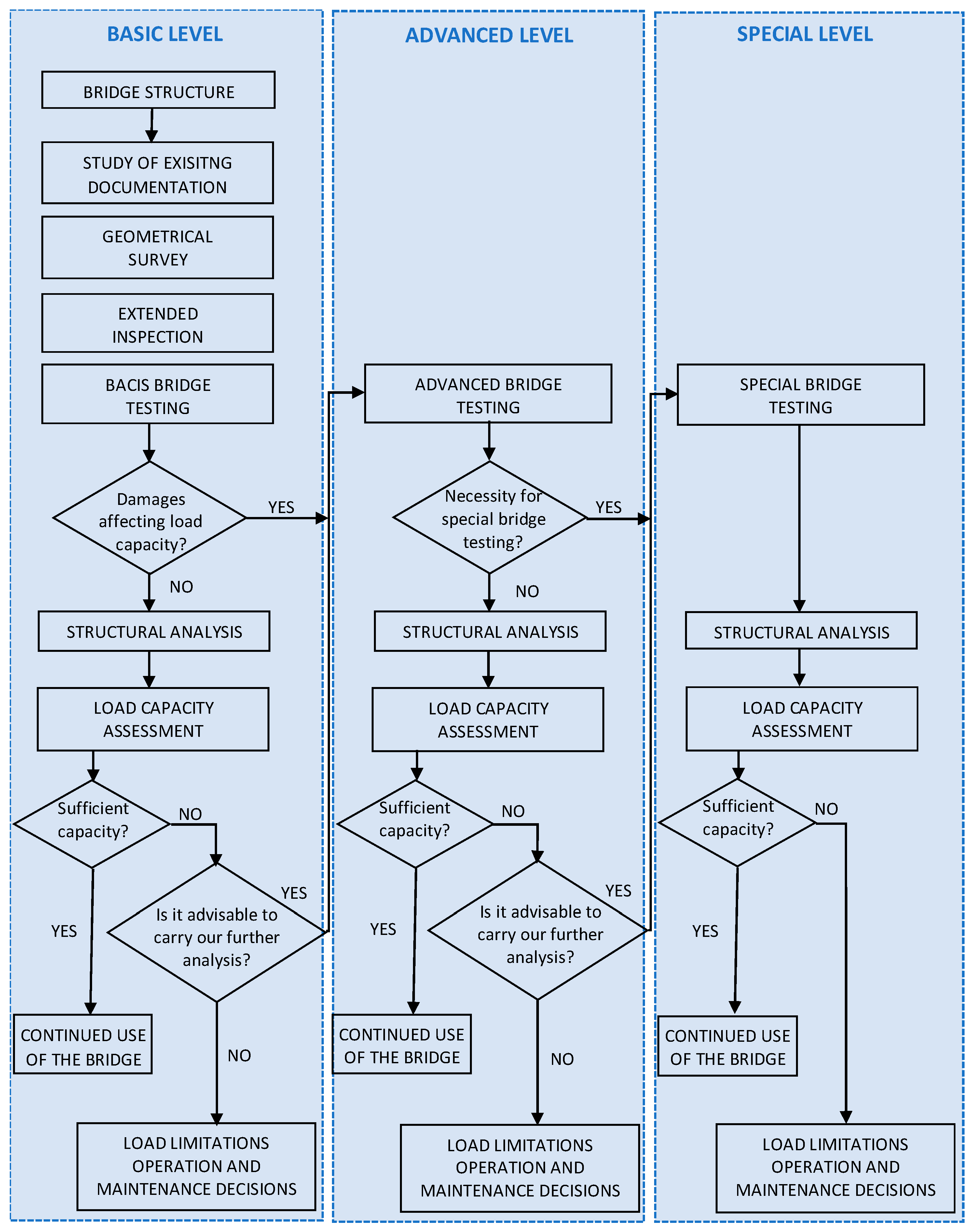
The assessment of the structural safety of the existing bridge should follow a stepwise framework with increasing levels of detail and accuracy (
Figure 1). The first level involves analysing archival documents, inventorying the bridge’s geometry (if necessary), conducting a condition survey (inspection), performing basic diagnostic tests, and executing simple computational analyses. Additional information, such as historical standards, construction strategies, and operation & maintenance experiences, is also essential. The assessment must consider the current condition of the bridge. Initial material properties can be derived from historical standards for different materials. Computational analysis involves re-evaluating the existing structure based on action forces and material parameters. At the second level, advanced diagnostic tests are required to identify detailed damage, among other things. Generally, updated characteristic values of materials are defined according to EN 1990, Appendix D [
44], based on material testing. Structural safety and serviceability verifications are carried out using these updated characteristic material values and modified partial factors, in accordance with the primary design equations of prEN 1990-2 [
43] within the partial factor framework. The advanced analysis (usually performed using the finite element method, FEM) considers the impact of identified failures on the bridge’s structural safety. The third level involves specialised diagnostic tests of the bridge under proof or service loads to evaluate its performance. The outcomes of these tests are primarily used to update and validate the FEM model employed in the final assessment of structural safety. Throughout each assessment level, the structural safety is evaluated to determine if it is adequate for continued use or if further analysis is advisable. Based on this, the bridge authority can decide on additional maintenance actions (e.g., traffic or service load restrictions, repairs, strengthening). Any interventions should, where possible, be designed in accordance with standards (Eurocodes) for new structures.
The criteria for selection and the scope of application for the appropriate assessment levels are as follows:
Basic level—used in the safety assessment of bridges where no damage could compromise the structure’s safety.
Advanced level—used in safety assessments of bridges where some failures might threaten the structure’s safety, and these failures can be fully detected using standard non-destructive or mildly destructive diagnostic tests, regardless of loads.
Special level—used in the safety assessment of bridges where some failures might impact the structure’s safety, and their detection requires non-standard diagnostic tests, including tests under proof and/or service loads (bridge performance tests).
The decision regarding which level of assessment to select should be based on the results of the initial condition survey of the bridge (inspection), conducted in consideration of the analysis of archival documentation and basic diagnostic tests. The recommendations for analysing the archival documentation of the bridge, as well as the methods and techniques used in diagnostic tests within the framework of assessing structural safety, complement the framework outlined in the specific guidelines [
47].
3. Bridge Description
The paper discusses a 55-year-old road bridge with a superstructure made from a steel-welded shell structure. In the 1960s, it was an innovative steel shell design inspired by shipyard structural solutions. It served as a load-bearing structure for belt conveyors, supported industrial installations, and was used in road bridge construction. Between 1970 and 1989, several similar bridges were constructed in southern Poland, with two still in operation today. Despite their innovative structural concept at the time, these steel shell bridges exhibited numerous structural and quality issues, which led to cracks in welded joints and local deformations after some years of service. For example, the superstructure of the first bridge, built in 1970, exhibited numerous cracks in the welded joints of the stiffening trusses within the shell just one year after its completion. Additionally, minor local deformations were observed in some truss elements, indicating possible overloading. Analysis revealed that vibrations from the tram rolling stock on the bridge caused these cracks. After two years, a new tram track with vibration isolation was installed, and the cracks were repaired. Nevertheless, similar damages occurred later in other bridges of this type, primarily due to their location on less busy roads. The extreme form of these issues is evident in the structure of the bridge discussed in this paper.
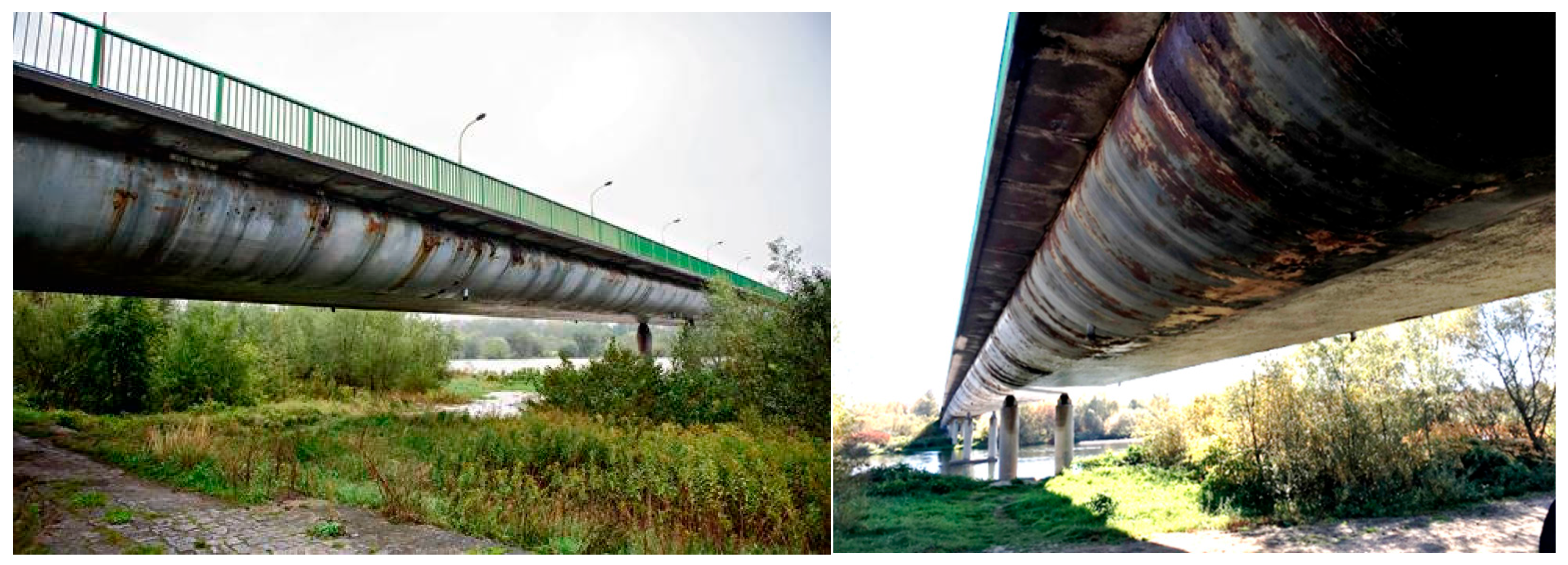
The bridge was constructed in 1970 and designed to withstand live loads according to the old Polish bridge standard from the early 1960s. It has a total length of 288.0 m and a static scheme of a five-span continuous beam with span lengths of 48.0 m, 60.0 m, 72.0 m, 60.0 m, and 48.0 m (
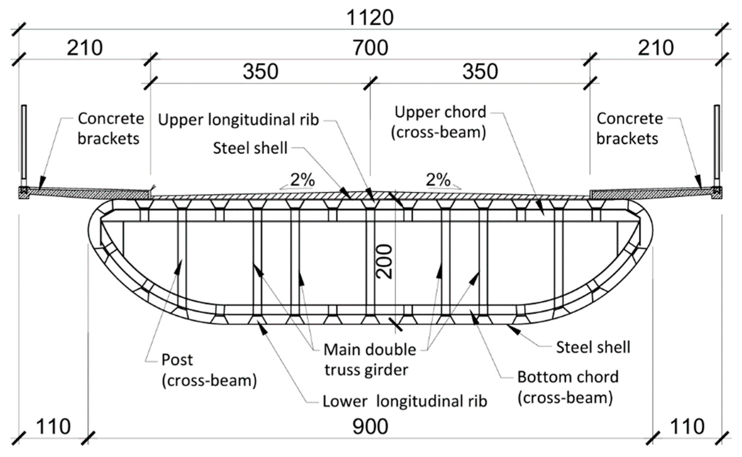
Figure 2). The overall width is 11.20 m, comprising a roadway with two lanes (2 × 3.50 m) and two sidewalks (2 × 2.10 m). The spans of the bridge were constructed as a steel shell structure, with a depth of 2.0 m and a width of 9.0 m (
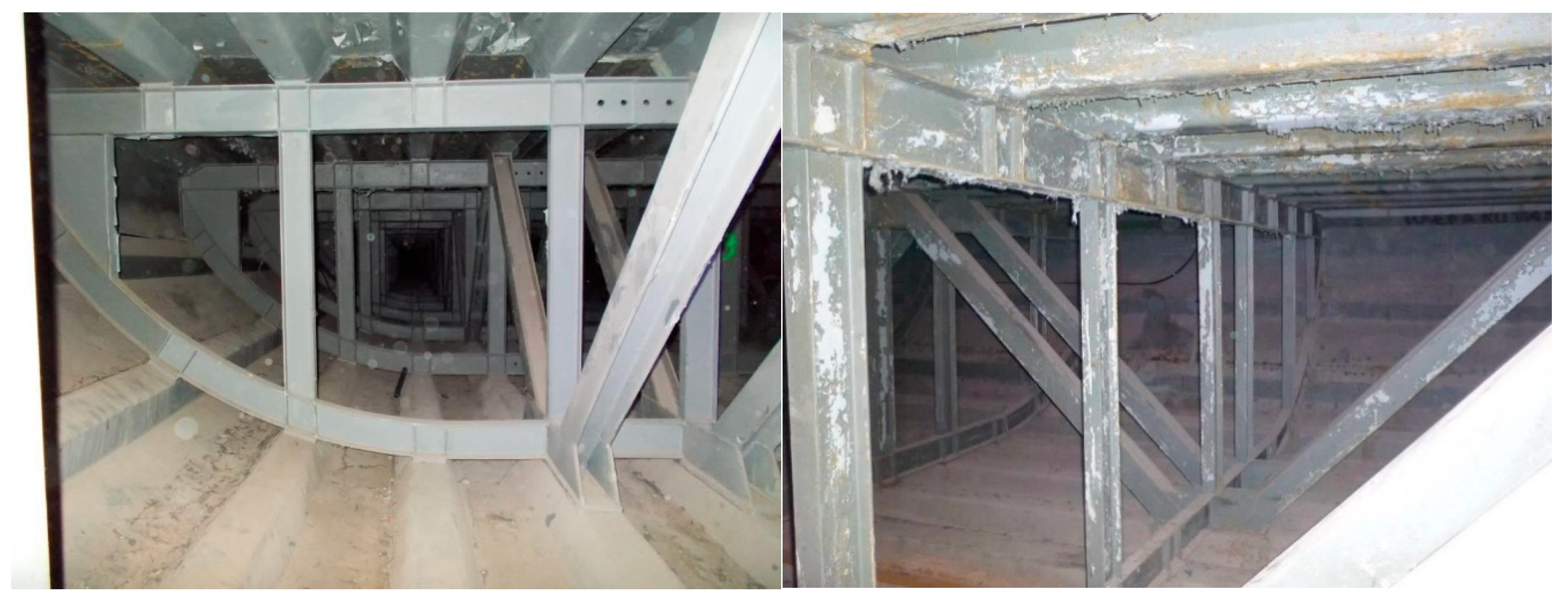
Figure 3). The shell, shaped like a basket curve, is made of steel sheets stiffened with longitudinal trapezoidal ribs. The top steel sheet with ribs forms an orthotropic steel deck. The shell superstructure is internally stiffened with steel trusses: four longitudinal trusses (arranged as two pairs) and numerous transverse trusses spaced every 2.0 m (
Figure 4). The first type of trusses features a standard triangulated system, acting both as longitudinal stiffeners for the shell and as the main load-bearing girders. The other, a Vierendel truss (or rigid frame), functions as a cross-beam. Both types are made from rolled or welded I-beams, with welded joints connecting all elements of the steel superstructure. Reinforced concrete prefabricated slabs are attached atop the steel sheets on both sides to form the bridge sidewalks.
4. Basic Level of Assessment Framework
The initial stage of the bridge assessment involved analysing archival documents. All available information was included in the evaluation, such as the original design and construction (including workshop) documentation (i.e., calculations and drawings from 1969) and subsequent inspections and previous assessment reports conducted during the structure’s service life. The inventory of the structure’s geometry confirmed that it was built strictly in accordance with the archival drawings. No structural modifications were made after the original construction, nor were any documented or discovered on site. Material or product properties were determined based on relevant documents from the time of construction. The bridge was designed for live loads according to the old Polish bridge standard, dated 1966, and the basic load-bearing capacity and safety conditions for the steel structure were checked using the allowable stress method, as outlined in the Polish standard for steel structures from 1958. Therefore, the existing steel structure did not meet modern safety standards for bridges based on limit states and partial safety factors. In particular, welded joints were designed and inspected using outdated methods, and the designer at that time did not evaluate the fatigue limit state of these connections. Furthermore, the static analysis of the complex spatial superstructure was performed using simple (one-dimensional) calculation models.
The current condition of the existing steel structure, including ongoing deterioration processes and present defects, was determined based on available information from inspection reports. A condition survey was conducted to update the understanding of the structure’s technical state, focusing on aspects critical to load capacity, safety, and reliability. The primary emphasis was on the structural elements that most significantly affect the safe performance of the steel structure. During the survey, the accuracy of as-built information was verified, and the superstructure’s actual main dimensions and boundary conditions were confirmed. All data collected during the study were incorporated into the modelling for structural analysis.
The condition survey showed that the steel shell, some longitudinal ribs, and parts of the trusses were superficially corroded (
Figure 2 and
Figure 4), mainly near equipment elements such as expansion joints, drainage inlets, and where the lighting lantern is attached to the structure, as well as at points where the prefabricated concrete slabs connect to the orthotropic bridge deck. Measurements of the thickness of these steel sheets and components indicated significant corrosion losses, reaching up to 3.0 mm in critical areas. The inspection also identified numerous (more than 100) severe plastic local deformations of the elements forming the trussed cross-beams (
Figure 5). These deformations reduce both the load-bearing capacity of the cross-beams and the overall stiffness of the spans. Their high number, plastic deformation, and localisation mainly in the support zones of the spans may point to overloading as the primary cause of their occurrence.
The most serious damage to the steel structure, identified during the condition survey of the bridge, was cracks in the welds (
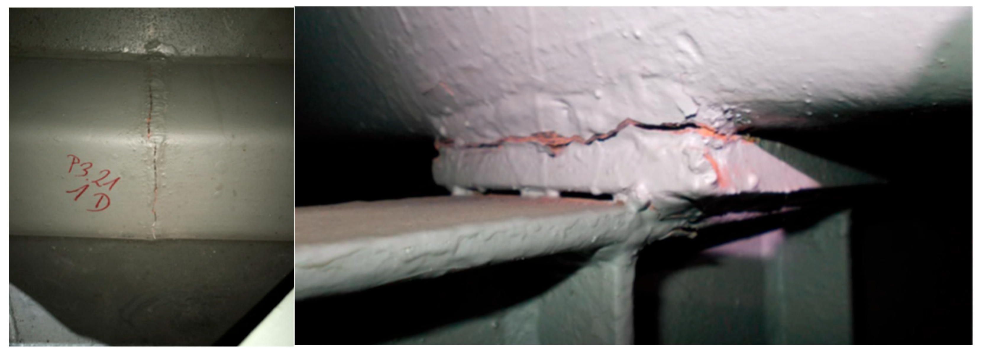
Figure 6). At this assessment level, most superstructure welds were examined using a combination of visual inspection and penetrant tests. The inspection revealed the poor condition of the butt welds of the shell’s longitudinal stiffening ribs. More than 40 cracks were discovered in the butt joints of the trapezoidal ribs, particularly located in the orthotropic deck at the support zones of the spans. These cracks disrupt the continuity of the longitudinal ribs, alter their static scheme and local internal force distribution, and negatively impact other structural elements, ultimately leading to their deterioration. For example, they caused cracks in adjacent fillet welds connecting the deck ribs to the upper chords of the cross-beams. More than 100 cracks (!) were found in these locations. The cracks varied in development, from hairline cracks that initiated weld destruction to complete joint break.
In most cases, the cracking of these joints was progressive, occurring 10 years after the initial repair of the welds, which revealed a permanent structural defect in this type of connection. Finally, several cracks were discovered in the welded joints between the upper cords of the main truss girders and cross-beams, particularly in the zones where the spans are supported. The primary cause of most cracks in welded joints is their poor quality, along with overloading and fatigue in some instances.
Following the assessment framework (
Figure 1), it was necessary to determine whether the observed failures of the steel structure had affected the safety of individual elements or the entire superstructure of the bridge. As is well known, cracks, plastic deformations, and severe corrosion are the leading causes of performance degradation in steel bridges. Cracks threaten the safety of the bridge and can even lead to collapse. In this case, most cracks in welded joints resulted from poor and faulty quality (many initial defects) and distortion caused by overloading or restraint issues. Furthermore, steel bridges, especially those with orthotropic decks, are susceptible to fatigue cracking due to prolonged wheel loading and high cyclic stresses. The significance of the crack for the bridge’s structural safety is of primary importance. If the crack is perpendicular to the tension direction induced by the service load, as shown in
Figure 6, it may compromise the bridge’s load-bearing capacity. Additionally, extensive plastic deformations in the cross-beams and local corrosion damage to the shells can substantially reduce the load-carrying ability. In summary, the damages observed in the steel superstructure, particularly their type and extent, may impact the structural safety of the bridge. Therefore, advancing to the second (more detailed) level of the assessment framework was necessary, as shown in
Figure 1.
5. An Advanced Level of Assessment Framework
An advanced assessment should be undertaken if the basic assessment has not demonstrated the bridge’s adequacy. According to the standard prEN-1990-2 [
43], an advanced assessment may include: detailed documentary searches and reviews; further structural investigations to update information about the structural system, actions and influences—including possible damage and deterioration mechanisms, material properties, ground conditions, etc.; structural analysis and verifications; recommendations for immediate interventions; and other suggestions such as additional assessment stages, potential future interventions, and future use of the structure. All these measures are encompassed in the new national framework (
Figure 1), with nearly all being applied in the case of the bridge in question. Since all archival documents found were used in the basic assessment, no detailed documentary search or review was necessary. Using archival static calculations, it was identified which elements and connections bear the most significant loads, and the structure’s load-bearing capacity was established. Identifying these critical points limited the scope of advanced inspections. The advanced assessment started with further structural investigations (such as measurements or tests) to update information about the structural system, including possible damage and deterioration mechanisms, covering aspects like structural conditions, behaviour, actions, and influences.
5.1. Advanced Bridge Testing
The purpose of the material tests was to determine the grade of structural steel (confirming compliance with the design documentation in this respect), its mechanical parameters necessary for structural analysis, and to assess the degree of steel weldability in case it would be required to strengthen the structure. The steel grade was determined using a spectral examination of the material composition with the Spectroport F emission spectrometer. The tests revealed that the structure was made of low-carbon steel type St3m (formerly the national steel designation), corresponding to the modern steel type S235 according to the standard EN 10025-2:2017-03 [
52]. Based on this, the characteristic yield strength of steel was assumed to be 235 MPa. The maximum carbon equivalent for the tested steel was calculated at 0.323%, which is below the threshold of 0.4%, indicating that the structural steel used to construct the bridge is easily weldable.
The advanced testing of welds aimed to identify damage that could affect the bridge’s load-carrying capacity. Welds without visible defects were selected for testing. Two types of welds were fully identified using NDT methods: the transverse butt welds in the longitudinal trapezoidal ribs of the orthotropic deck and the fillet welds connecting the longitudinal ribs of the deck with the upper chords of transverse cross-beams. Based on weld type and size, the first were tested using ultrasound, while the latter were tested using the magnetic-particle method. Ultrasonic testing of the selected transverse butt welds was conducted using an ultrasonic flaw detector, type Epoch 600, in accordance with the standard EN ISO 1764:2018-01 [
53]. The purpose was to detect subsurface discontinuities in the welds. The entire surface of the transverse joints was examined along their length. A total of 23 welds were tested, and no cracks were observed during visual inspection. However, all tested welds revealed severe discontinuities such as cracks and/or lack of penetration, indicating very low quality. The most extensive cracks reached up to three-quarters of the weld’s length. The poor quality of the welds was mainly responsible for the large cracks. Additionally, numerous structural notches and cyclic loading of the bridge decks contributed to fatigue, which accelerated the growth of cracks.
Magnetic particle tests on selected welds were performed using a magnetic jet flaw detector AC42 K+D Flux Technic type, following standards EN ISO 9934-1:2017-02 [
54] and EN ISO 17638:2017-01 [
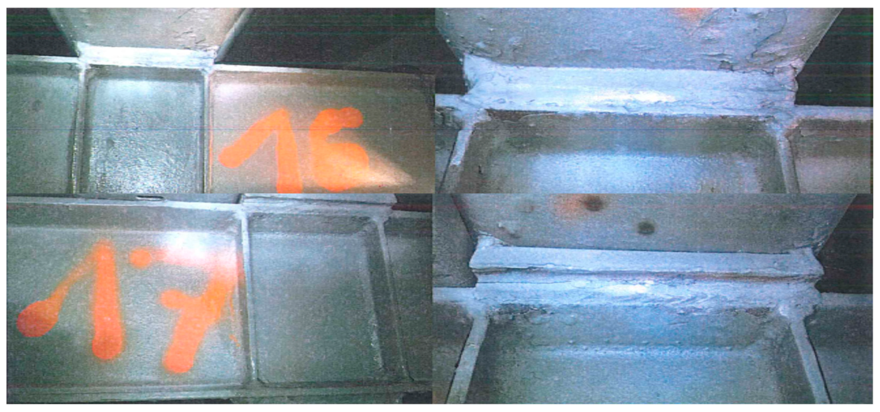
55]. The purpose was to detect surface and subsurface discontinuities in the fillet welds connecting the longitudinal ribs of the deck to the upper chords of the transverse cross-beams. The examination covered 22 welds, which showed no cracks based on visual inspection. The surface and subsurface of the joints were inspected over an approximately 20 mm area. On all tested welds, several inadmissible indications (i.e., flaws with l > 2 mm and/or d > 1 mm) were found on the surface, indicating very low weld quality (
Figure 7).
The observed discontinuities in the fillet-welded joints connecting the orthotropic deck and the cross-beams may lead to a lack of composite action between these elements, as assumed in the original design. Consequently, it was also investigated whether these discontinuities had a significant impact on the overall stiffness of the superstructure. The potential change in stiffness was evaluated by measuring the permanent deflection at the midpoint of the longest span (L = 72.0 m) using precision levelling. The average measured permanent deflection was 105 mm (L/686), which is considered substantial after 55 years of bridge operation, especially since the superstructure was initially built with reverse deflection. This indicates that the flaws found in the welded joints of the steel structure considerably reduce the overall stiffness of the spans.
5.2. Structural Analysis
The next step in the advanced-level assessment framework is the structural analysis (assessment by calculation). If an evaluation by calculation is performed, the values of actions and resistances should be considered for the limit states in the calculation situations being assessed. The rules for action combinations should also be consistent with the assessment situations relevant to the structure. The combination rules were taken from EN 1990 [
44]. The identified damage and deterioration rates, along with their impact on structural performance and load-carrying capacity, are incorporated into the calculation models based on the available information obtained to date.
The structural analysis of the steel superstructure was conducted using the finite element method with a three-dimensional numerical model created in SOFISTIK version 2024 software. Information related to the structural system—such as the layout of the structure, arrangement of individual structural elements, and overall dimensions—was obtained from design documents. The numerical model accurately reflected the structure’s geometry and components based on these documents, which, in some cases, were verified through inspection data (e.g., thickness of steel sheets). If the records did not contain the necessary information or if there were doubts about their accuracy, the structural model was updated during the initial inspection of the inventory. The assumptions regarding the static and kinematic boundary conditions of the structural system, including those related to support conditions, were confirmed to be valid.
Shell (quad) and beam finite elements were used to model the superstructure. Depending on the structure’s geometry, the appropriate type of finite elements and meshing techniques were selected to generate the mesh. A general meshing approach was employed to ensure all nodes in contact areas converged. An ordered reticulation method was applied. The four-node shell elements discretised the superstructure shell with a maximum size of 300 × 500 mm. Mesh refinement using shell elements of size 150 × 500 mm was carried out for the longitudinal trapezoidal ribs. Various shell sheet thicknesses, as well as different types and sizes of ribs and truss sections, were considered. Two-node beam elements were used to model the internal trusses of girders (posts, diagonals, and both transverse chords). The actual thicknesses of individual truss elements, which vary across the cross-section of the bridge span and along its length, were incorporated into the model. The truss connections were modelled as rigid, transmitting the bending moment, on a standard grid of nodes. In the key connections between the transverse upper chords and the trapezoidal longitudinal ribs, restrictions were introduced using spring elements (spri). The spring elements connecting the nodes of the upper chord with those of the longitudinal ribs were given maximum rigidity by modelling the welded joint. Axial stiffnesses of 10
16 kN/m
3 were assumed in three orthogonal directions. Additionally, the spring elements in the three orthogonal bending planes have flexible stiffnesses of 10
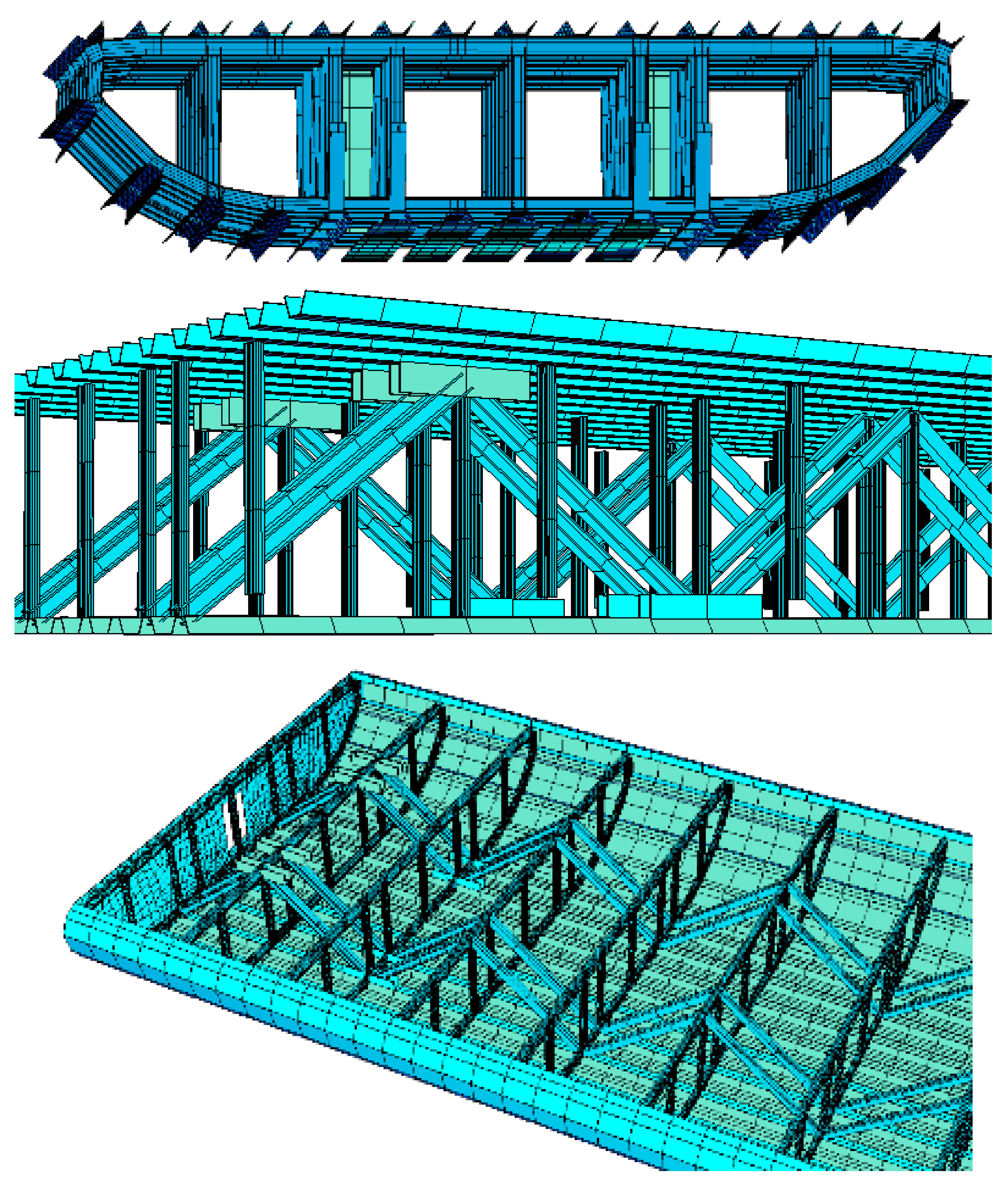
16 kN/rad/m in each plane. This node model represented a welded joint with full rigidity, free from damage. The visualisation of the numerical model of the steel superstructure is shown in
Figure 8.
The results of the condition survey and advanced bridge testing were integrated into the model, including corrosion losses of deteriorated elements and cracks in the fillet welds between the longitudinal ribs of the deck and the upper chord of the cross-beams. The latter failures were simulated by removing the axial stiffness in the (x) and (y) directions, along with the corresponding bending stiffnesses in the same planes. An axial stiffness of 1 kN/m3 in these two directions and a matching bending stiffness of 1 kN/rad/m in the same planes were introduced. In the (z) direction, the full axial stiffness, namely 1016 kN/m3, and the corresponding full bending stiffness of 1016 kN/rad/m were retained, thereby modelling the pressure in the gravitational direction.
The material properties of the finite elements were assumed to be derived from and updated based on analysis of design specifications and construction records, corroborated by the condition survey and material testing results. Based on the material tests conducted, the parameters of the structural steel were found to align with those of modern S-235 steel. At this stage of the structural analysis, steel was modelled as a linear-elastic isotropic material using two engineering constants: E and ν. The material constants for steel and strength parameters were assumed to be E = 210 GPa, ν = 0.3, and fy = 235 MPa.
According to prEN-1990-2 [
43], traffic loads on existing bridges should be assumed using the same live load models established in EN 1991-2 [
48] for designing new bridges. However, case-specific traffic load models may be specified by the relevant authority, based on the actual traffic characteristics and the traffic forecast over the remaining service life. In our case, the traffic load models used to evaluate the bridge’s load-bearing capacity were adopted in accordance with the requirements of the Polish road administration [
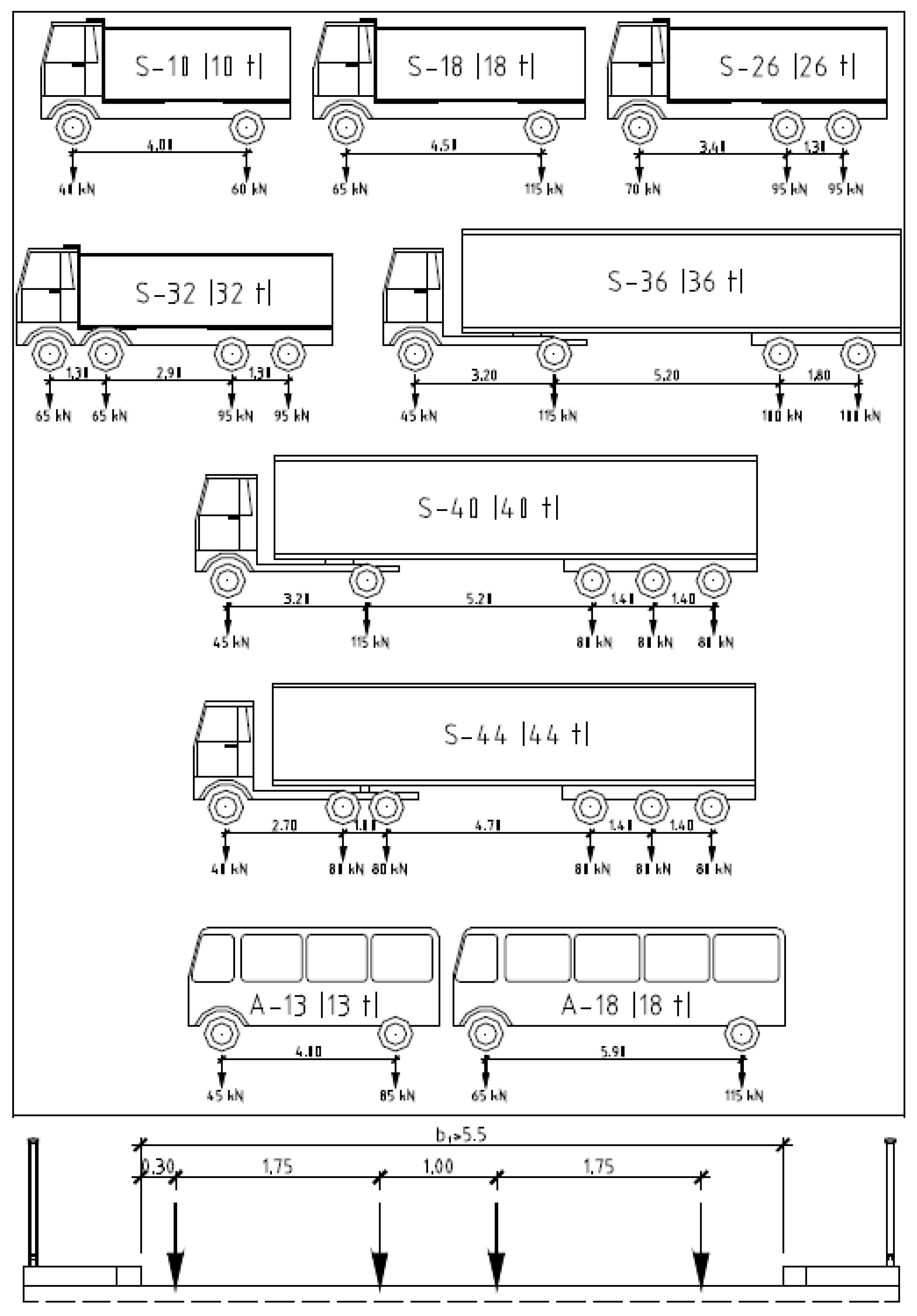
9]. The vehicle schemes, loads, and markings, as adopted as actual traffic loads in the structural analysis, are shown in
Figure 9.
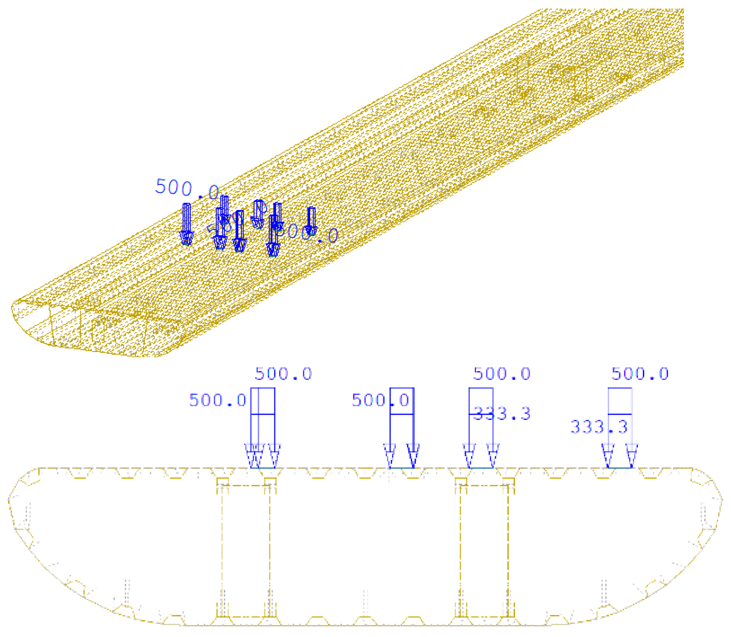
The single vehicles, as shown in
Figure 9, were used in the numerical analysis as a surface load (pressure) of a single wheel, acting on the actual surface of the upper deck plate, considering a wheel load area of 0.30 × 0.40 m. An example of the load position of the traffic vehicle, marked as 2×S10, is shown in
Figure 10.
The following traffic vehicles, according to
Figure 9, were set to move along the length of the bridge spans, assuming two possible combinations:
Unrestricted traffic: single vehicles moving individually in both directions on each lane of the bridge roadway, occupying the most disadvantageous position from the perspective of the calculated static value.
Shuttle traffic: individual vehicles moving separately in one direction on a single lane of the bridge road, occupying the least favourable position from the calculated static value’s perspective.
The analysis also assumed that no other vehicles were on the bridge roadway apart from the single vehicles of each type.
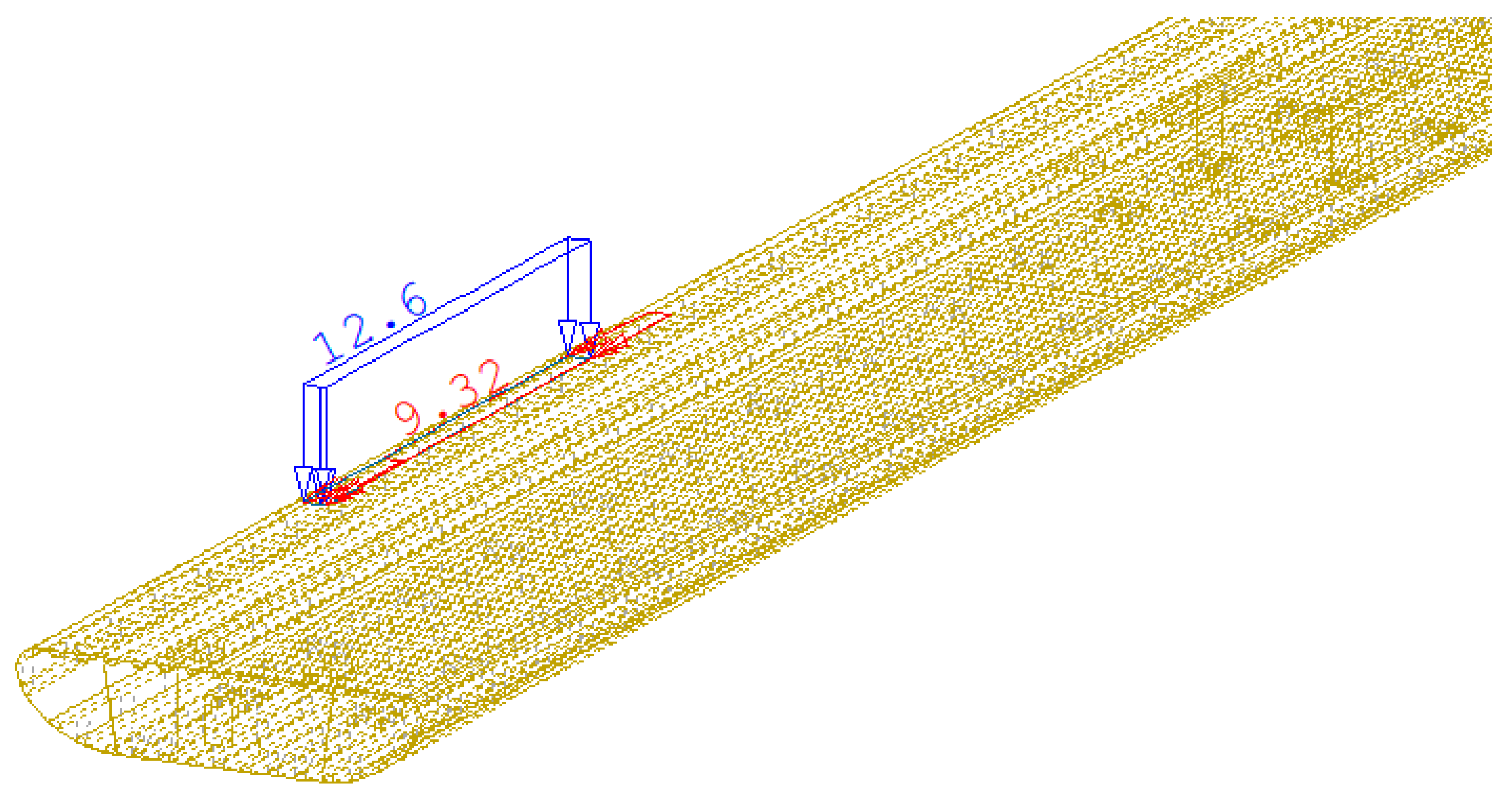
Other actions were implemented in accordance with the relevant Eurocodes. The self-weight of the structure or its elements, as well as other permanent actions, was determined based on the relevant geometrical properties and material densities. The pedestrian load, with a characteristic value of 5.00 kN/m
2, was applied to the actual contact area between the prefabricated concrete slabs and the orthotropic deck, spanning a width of 0.50 m and the entire length of the bridge. The pedestrian load was modelled as a surface load on the top plate of the steel deck, acting in the gravitational direction with the corresponding bending moment related to the transfer of the load’s centre of gravity (
Figure 11). The load was modelled separately for both sidewalks, varying along the length of the bridge. The analysis also included the effect of temperature changes at the depth of the steel structure. The temperature difference for the simplified model at the extreme fibres was assumed to be 18 °C for heating and 13 °C for cooling (
Figure 12). The scenario of uniform heating and cooling actions on the structure was not considered in the calculation.
The action combinations followed EN 1990 [
44], using the partial safety and combination factors shown in
Table 4. These combinations were created to simulate the most severe conditions of the considered actions.
5.3. Structural Safety Verification
The ultimate limit state (ULS) verification (or structural safety verification) was performed using the limit state method with the inequality given by Formula (1):
where
Ea is the assessment value of the effect of actions;
Ra is the assessment value of the resistance.
Ea and
Ra can be expressed as functions of the assessment values of the basic variables, including the relevant partial safety factors and combination factors. In our case, the equivalent stress according to the Huber-Mises-Hencky strength criterion (H-M-H) was taken as the assessment value of the effect of actions
Ea, while the design strength of structural steel, determined based on material tests and archival documents, was used as the assessment value of the resistance
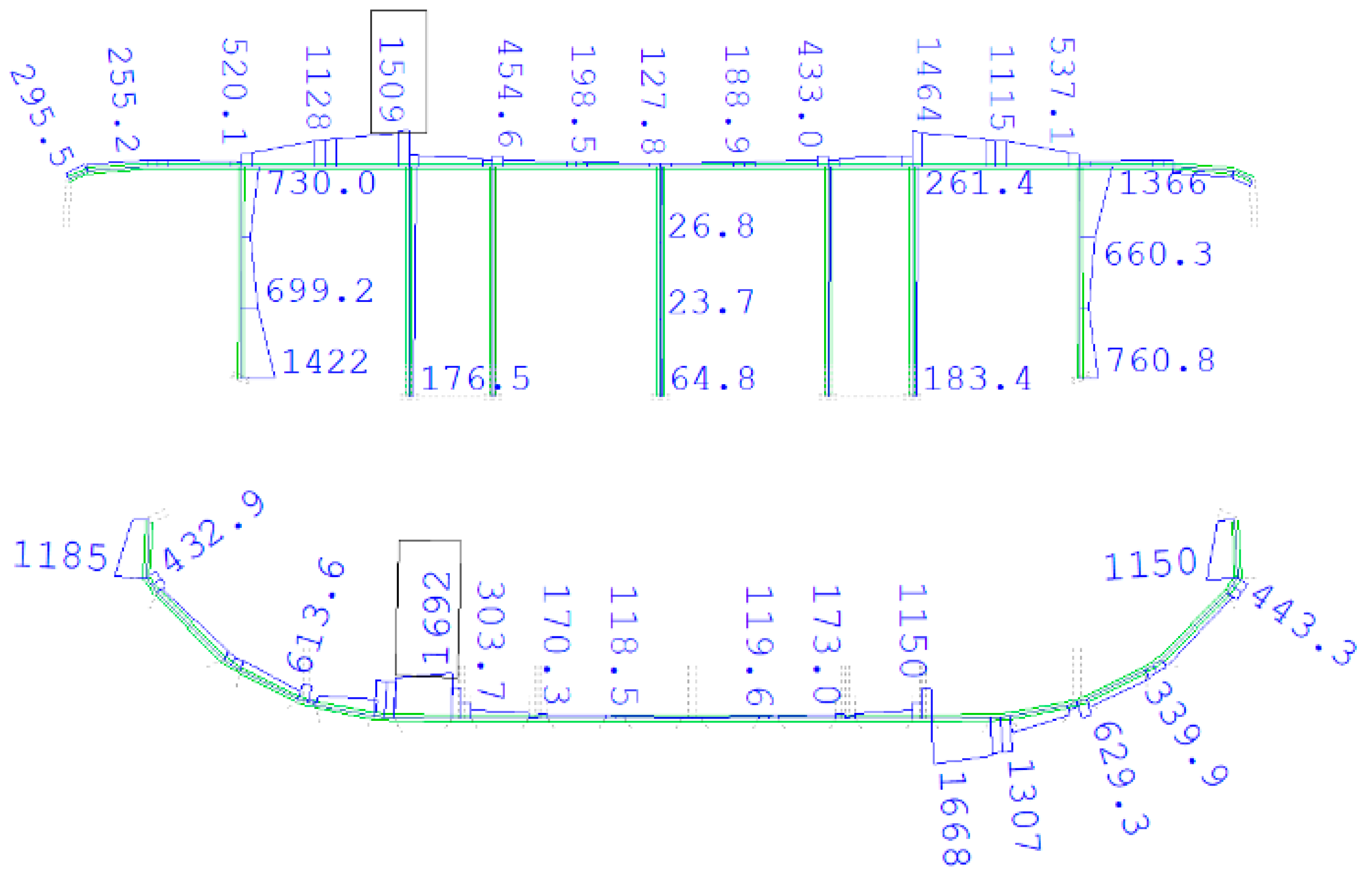
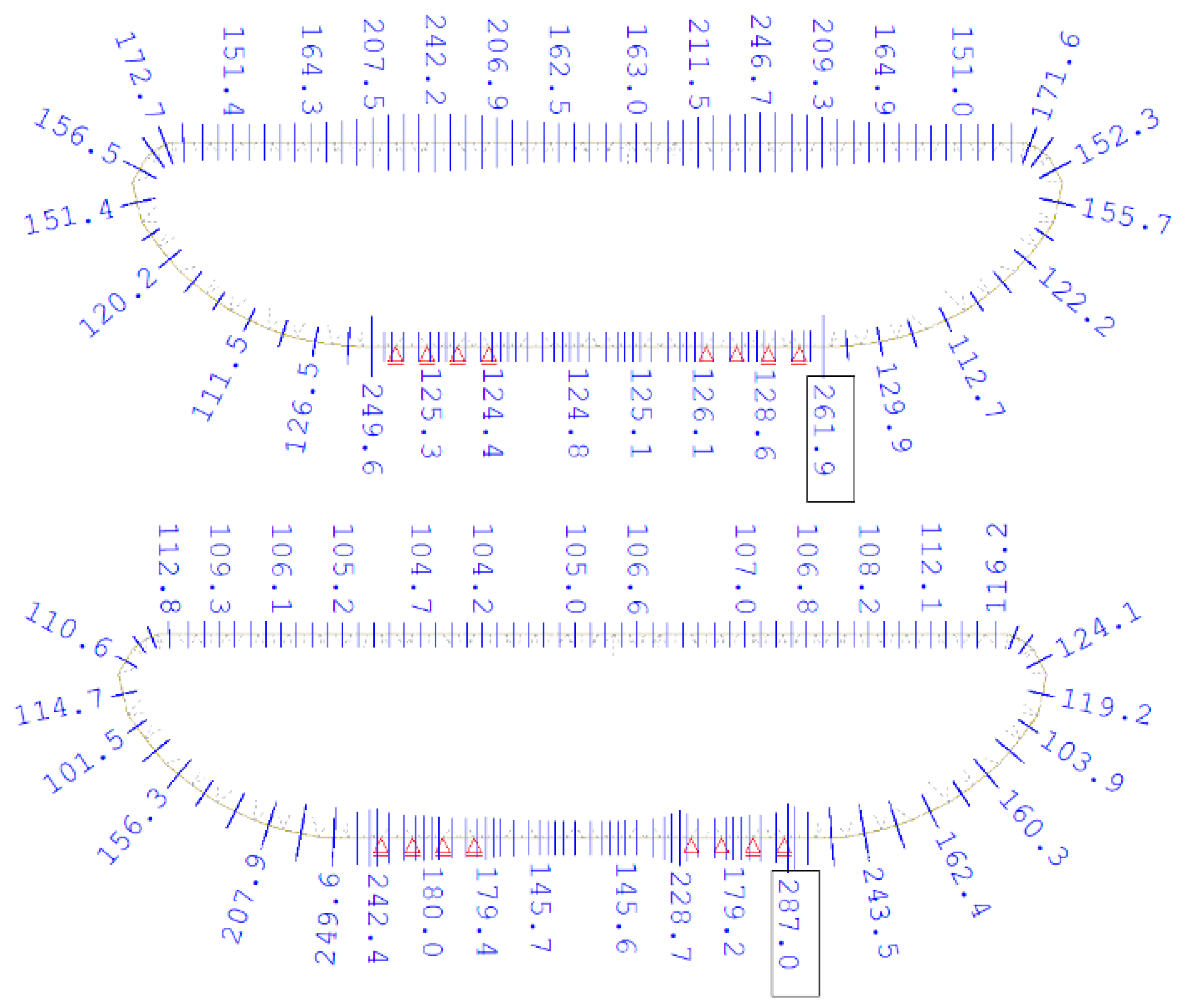
Ra. The relevant load and material partial safety factors, as well as combination factors, were applied to both assessment values in accordance with the Eurocodes. Consequently, using Formula (1), the ultimate limit state (ULS) of individual superstructure elements was verified. Since the structure lacked sufficient ductility for the required deformations (due to cracks), plastic redistribution was not considered for assessment at the ultimate limit state. The selected results of the ULS analysis, presented as H-M-H stress plots, are shown in
Figure 13,
Figure 14 and
Figure 15.
Although the FEA results are displayed visually in the figures above, tabulated stress values or safety margins for key elements would enhance transparency and clarity. Therefore, in
Table 5, these values are additionally provided for selected elements of the steel superstructure.
The assessment of the steel superstructure revealed that the structure lacks a sufficient safety margin regarding the ultimate limit state (ULS), even when subjected to the weight of a traffic vehicle of the lowest class, 2 × S-10 (a vehicle with a total weight of 10 tonnes). The main steel elements responsible for the superstructure’s insufficient safety are as follows:
Longitudinal truss diagonals—the assessment value of the resistance (Ra) is exceeded by up to 5%; number of deficient elements—4;
Upper chord of cross-beams—the assessment value of the resistance (Ra) is exceeded by up to 550% (!!!); number of deficient elements—20;
Lower chord of cross-beams—the assessment value of the resistance (Ra) is exceeded by up to 620% (!!!); number of deficient elements—20;
Cross-beam posts—the assessment value of the resistance (Ra) is exceeded by up to 505% (!!!); the number of deficient elements is 120.
The shell sheets of the superstructure, its longitudinal stiffening ribs, and its upper part, the orthotropic deck, have sufficient safety regarding ULS; however, only for the lowest class 2 × S-10 traffic vehicle. Additionally, the analysis showed that the resistance values of some of the elements mentioned above were exceeded under self-weight and permanent load (by up to 200%). A comparison between analysis results and the condition survey indicated the same elements, where local plastic deformations were observed (
Figure 5). The structural analysis revealed that more than 180 superstructure elements are insufficiently safe to carry the actual minimum traffic loads with the safety level required by the new national guidelines [
47] and the European standard prEN 1990-2 [
43].
5.4. Maintenance Decisions
According to the European standard EN 13306:2010 [
56], the general definition of maintenance is given as the “
combination of all technical, administrative, and managerial actions throughout the life cycle of an item intended to keep it in, or restore it to, a state in which it can perform the required function”. It is clear that determining appropriate maintenance actions is a complex decision-making process; that is, several decisions must be made regarding which actions are relevant, how they should be implemented, when they should be executed, who should be responsible, and how many resources should be allocated. To optimise these decisions, they need to be supported by information about the actual technical condition (including load-carrying capacity) of the specific asset.
Considering the poor technical condition of the steel superstructure (corrosion, numerous cracks in welds, and local deformations) and the results of the structural safety assessment, which essentially disqualified the continued use of the steel structure for the bridge’s operation, the fatigue life analysis (typically conducted in such cases, see [
57]) and the special bridge testing were deemed unnecessary. Because of the very low structural safety of the superstructure (even under self-weight and permanent load) revealed during the assessment, the bridge authority decided not to impose any traffic restrictions (such as vehicle load or speed limits, or operational constraints). Instead, they ordered the immediate closure of the bridge until a decision was made on whether to repair/strengthen or replace the superstructure. However, repairing or strengthening the steel structure would involve extensive work and high direct costs. Furthermore, the life cycle cost analysis comparing repair versus replacement convinced the road authority to replace the superstructure completely. Over the following two years, the old steel superstructure will be replaced with a modern steel–concrete composite structure supported on new piers with reinforced existing foundations.
6. Conclusions
The structural safety assessment of the existing steel bridge, considering the technical condition of the structure and current traffic loads, showed that the steel superstructure did not meet the required safety standards according to the new national Polish guidelines, based on the prEN-1990-2 standard for assessing existing structures. The following detailed conclusions were drawn from the assessment:
More than 180 superstructure elements are insufficiently safe to support the actual minimum traffic loads with the safety level required by the new national guidelines and the European standard prEN 1990-2.
The resistance values of some structural elements were exceeded even under self-weight and permanent load (by up to 200%).
The condition survey indicated local plastic deformations in the same elements, demonstrating a lack of load-bearing capacity based on the assessment.
The remaining superstructure elements have sufficient safety concerning ULS; however, only for the lowest class 2 × S-10 traffic vehicle.
The structural analysis revealed a very low level of structural safety, significantly below the standards established by the Eurocodes. This is primarily due to the inadequate structural analysis of the highly complex steel structure conducted during the bridge’s design in 1969. Additionally, observed failures such as cracks in welds and local deformations significantly compromise the bridge’s safety. In this situation, permitting any traffic load on the bridge would pose a direct threat to its safety and that of its users. Therefore, it was recommended that the bridge be closed to public traffic and replaced with a new structure.
The new guidelines for the structural safety assessment of existing road bridges act as a tool to support decision-making by road authorities. According to the initial assumptions of the Ministry of Infrastructure, the guidelines may be utilised, among other things, in cases such as (needs): lack of maintenance information from the previous operational period of the bridge; doubts or irregularities observed during bridge monitoring; an increase in service load due to changes in road classification; determining the military load class (MLC) for bridges on public roads; evaluating the extent of structural modifications needed for rehabilitation or strengthening of existing structures; and so on.
The application of the new guidelines has eased the assessment of the complex steel bridge in accordance with the unified principles introduced across the European Union through the implementation of the prEN 1990-2 standard. This new standard represents a significant step forward, as it is among the first international design codes to specifically focus on assessment. The new Polish guidelines standardise, at a European level, methods for evaluating existing structures and outline the criteria to consider when investigating and appraising existing bridges, while also establishing differences compared to conventional design for new structures. The authors emphasise that particular importance was given to understanding the structural configuration and the most probable failure modes in existing structures, as this provides a crucial basis for planning and conducting verifications most suitable and necessary for each case to evaluate the safety, durability, and functionality of the structure.
The application of these new national guidelines to assess the structural safety of an existing 55-year-old bridge, as discussed in the paper, highlights their practical significance. The scientific significance of the paper lies in presenting new Polish national guidelines for assessing existing bridges, developed with the authors’ participation as a national implementation of the new Eurocode prEN 1990-2. The paper illustrates the application of these guidelines using a complex steel bridge structure with poor technical condition. This example could serve as a benchmark for similar assessments carried out in accordance with the new Eurocode, making it of considerable practical importance. However, it should be noted that the assessment procedure was not completed (i.e., the special level was not used) due to the critical condition of the bridge and the urgent need to close it.
