1. Introduction and Literature
A continuum robot is a sophisticated robotic system distinguished by its unique design featuring a flexible and bendable section. This advanced robot’s form is dynamically controlled by manipulating its bendable segment, enabling it to adapt and conform to various shapes and contours. The distinct advantages continuum robots offer in comparison to conventional rigid-link robots are profound. One of the primary benefits lies in its remarkable ability to traverse along the intricate curves and surfaces of objects by manoeuvring its tip within confined spaces. This exceptional manoeuvrability opens up a new dimension of possibilities for applications requiring precision and agility in constrained environments. Moreover, the inherent softness of continuum robots, attributed to their bendable structure, plays a pivotal role in their operational superiority. This softness ensures gentle interactions with delicate and fragile objects, thereby minimizing the risk of damage—a critical feature when working in open spaces or handling sensitive materials.
Continuum robots possess a remarkable advantage in their infinite degrees of freedom and the abundance of joints, enabling them to dynamically adjust and reshape themselves at any position along their length [
1]. This unique capability empowers continuum robots to navigate and function effectively in tight, intricate environments that are beyond the reach of traditional rigid-link robots. The versatility of continuum robots in adapting their form to suit the requirements of diverse tasks makes them a promising solution for a wide range of applications. In the field of medical devices, continuum robots are poised to revolutionize procedures requiring precise and minimally invasive interventions [
2]. Their ability to manoeuvre through intricate pathways with ease makes them ideal candidates for applications such as endoscope sheaths and catheters, where delicate control and access to hard-to-reach areas are paramount. The flexibility and dexterity of continuum robots offer healthcare professionals a level of precision and control that can enhance diagnostic accuracy and therapeutic outcomes. Furthermore, the adaptability of continuum robots extends beyond medical settings to encompass extreme work environments, including search and rescue missions [
3]. Their capacity to navigate through complex terrains and confined spaces with agility makes them invaluable assets in scenarios where human access is limited or hazardous. By leveraging the unique capabilities of continuum robots, rescue teams can enhance their efficiency and effectiveness in locating and extricating individuals in challenging conditions.
The actuation of continuum robots remains a significant challenge, prompting the development of diverse actuation mechanisms to tackle this obstacle [
4]. Two primary categories based on the location of actuation mechanisms have emerged: extrinsic actuation and intrinsic actuation systems. Extrinsically actuated robots rely on external actuators to drive the robot’s movements, whereas intrinsically actuated robots integrate actuators within the robot’s structure, enhancing compactness and efficiency [
5,
6].
In addition to these conventional actuation methods, some continuum robots leverage the unique properties of materials or fluids to achieve control and manipulation. By harnessing the inherent characteristics of specific substances, these robots exhibit novel modes of actuation that expand their operational capabilities and adaptability to varying tasks and environments [
7]. Furthermore, within the realm of continuum robotics, geared-based and motor-based systems represent alternative approaches to actuation. While geared mechanisms offer precision and power transmission, they may be deemed unsuitable for certain applications due to concerns such as size constraints and complexity [
8]. Motor-based systems, on the other hand, provide a versatile and direct means of actuation, enabling controlled and efficient movement in a variety of scenarios. The exploration of diverse actuation mechanisms underscores the ongoing innovation and evolution within the field of continuum robotics, paving the way for enhanced performance, versatility, and applicability across a broad spectrum of industries and applications.
Numerous endeavors have been dedicated to enhancing the design and actuation systems of continuum robots, with a particular focus on refining wire actuation mechanisms. Wire actuation has emerged as a prominent method, undergoing multiple developmental iterations. This mechanism allows for the external control of individual segments or clusters of segments at specific points by manipulating the tension in the wire. An example of such innovation can be found in patent WO2019055701A1 [
9], showcasing the ongoing exploration and experimentation within this domain.
Moreover, the work in patent JP2019058648A [
10] reveals an innovative continuum robot configuration that incorporates multiple curved sections, such as a distal curve part and a proximal curve part, each of which is curved using at least one wire. This design includes a drive body responsible for wire actuation, a controller tasked with regulating the wire’s actuation level, and a movable base that can facilitate the robot’s movement.
In the described system, when the base imparts a displacement value to the continuum robot, the distal curve part initiates a rotary motion. This rotary motion spans an angle equal to or greater than a specific degree. Notably, the controller ensures that the proximal curve part does not undergo rotary motion exceeding a defined degree. Instead, it monitors the curvature state of the distal curve part upon the completion of its rotary movement and orchestrates the proximal curve part to mirror the movements of the distal curve part accordingly, thus ensuring synchronized and coordinated motion within the continuum robot design.
Nevertheless, the wire-actuated approach continues to grapple with a notable drawback concerning the resolution of bending movements. Achieving fine control over the bending behaviour demands either a significant quantity of wires dedicated to individual segment manipulation or a compromise in resolution by employing a single wire to govern multiple segments simultaneously. This dilemma underscores a key challenge in the wire actuation domain, where striking a balance between control precision and practicality remains a persistent concern.
An alternative actuation mechanism in the realm of continuum robots involves the utilization of pre-curved tubes, leveraging pre-shaped components for telescopic extension and axial rotation. For instance, patent US10737398B2 [
11] introduces a device featuring an elastic support member, one or more rods pre-bent in their resting state, and a series of support discs, each equipped with multiple apertures. These apertures are designed to accommodate the pre-curved rods, which are composed of material with differing stiffness compared to the elastic support member.
The elastic support member is affixed to the support discs to uphold the spacing between them. As the pre-curved rod slides within the apertures, it adjusts the positioning of the support discs and coerces the elastic support member to conform to a specific shape dictated by the rod’s placement. This mechanism offers a distinctive approach to actuation, showcasing the potential for intricate and controlled movements within continuum robotics through the manipulation of pre-curved components.
Furthermore, within the realm of robotics research, a plethora of studies have been dedicated to advancing multi-degree-of-freedom robots and manipulators capable of achieving continuum deformation and enhanced stability. One notable innovation in this domain is the development of flexible bio-tensegrity manipulators.
Moreover, researchers have explored synthetic methodologies to design and deploy multi-degree-of-freedom tuned mass dampers, specifically targeting the damping of bending motions. Despite these advancements, the inherent challenge persists: the pre-curvature of tubes imposes constraints on the path-following capabilities of these systems and complicates the control of multi-degree-of-freedom bending actions. This limitation underscores the ongoing need for novel solutions to address the complexities associated with achieving precise and versatile bending movements in continuum robotics.
Recent developments in robotics have witnessed a significant shift towards the exploration of magnetically driven mechanisms for the precise control of multi-degree-of-freedom bending. This shift is primarily motivated by the remarkable capabilities of magnetically driven actuator systems to produce substantial actuation forces by harnessing remotely generated magnetic fields effectively [
12]. The magnetically driven actuator mechanism typically relies on the integration of soft flux actuator modules, which are commonly associated with two conventional electromagnetic coils, enabling intricate and versatile control over complex robotic movements [
13]. Soft, flexible, and stretchable materials have emerged as pivotal elements in the domain of magnetically driven actuation, exhibiting their adaptability as soft actuators tailored for a diverse range of soft robotic applications [
14]. These materials exhibit intrinsic characteristics that enable seamless incorporation into robotic structures, facilitating dynamic transformations and responsive behaviors to external stimuli.
Polydimethylsiloxane (PDMS) robots are made from a flexible silicone material that can stretch or be deformed, allowing them to engage delicate objects or environments. These robots take their design cues from biological organisms in terms of flexibility and contribute to applications such as soft robotics research, models of medical procedures, and studies of human–robot interaction. The advantages of PDMS robots include compliance, usability in complex environments, and the ability to perform operations that are difficult for rigid robots. For evaluating an electromagnetic continuum robot by forming PDMS-based robots, there are specific advantages along with limitations. While the robot design so developed with its specific dimensions and other components can induce many advantages, including higher precision in control due to well-defined structures, the system components coupled with driving circuitry include more intricate movements with functionalities ranging from simpler to more complex designs and add an obvious level of complexity in the capabilities of the robot. The PDMS robots’ disadvantages include limited holding capacity by soft PDMS, difficulties in controlling movement in an external magnetic field, durability and wear and tear, sensor integration for feedback and autonomous action, and environmental limitations of material properties. The process of manufacturing PDMS-based robots can also be more complicated than that of rigid-on structures and introduce problems arising from limited rigidity affecting stability and precision together with the likelihood of interference by external magnetic fields. Thus, the choice between the two designs depends on the application requisites and parameters like accuracy, maneuverability, flexibility, and ease of fabrication.
In a notable illustration of the magnetically driven mechanism, patent US2022143817A1 [
15] describes an electromagnetically actuated robotic system. This system integrates electromagnetic coils, a charge storage unit, one or more processors, multiple electrically conductive pathways, and, optionally, sensor elements, all precisely embedded within or mounted on an elastomeric body. This innovative design allows for the alteration of the shape, movement pattern, and electrical characteristics of the robotic device through the selective activation of one or more electromagnetic coils. The patent application further delves into methods for the fabrication and utilization of such electromagnetically actuated robotic devices, offering insights into their construction and operational strategies.
Nonetheless, there remains a pressing need for the advancement of enhanced magnetically driven robotic systems capable of achieving multi-degree-of-freedom bending while maintaining controlled motion at any desired angle. This imperative underscores the ongoing quest for innovations that can effectively combine the benefits of magnetic actuation with precise angle control, paving the way for more sophisticated and versatile robotic applications [
12,
16,
17].
The technical challenge highlighted above underscores the objectives of the present work. One primary aim is to introduce a controlled motion system leveraging electromagnets and springs, enhancing the precision and predictability of movements within the robotic system. Another key goal of this innovation is to devise a mechanism tailored for a multi-segmented continuum robot. This mechanism is designed to enable independent bending of each segment, thereby collectively granting the robot increased degrees of freedom in its motion trajectory. By empowering individual segments to flex autonomously, the robot gains enhanced adaptability and versatility in navigating complex environments and executing tasks with greater agility and efficiency. Our initial design concept, along with its corresponding proof of concept, has successfully secured a patent under registration number SA14960B1 [
18]. In this work, we present an in-depth exploration of the design intricacies and provide a comprehensive overview of the simulation results obtained from the prototype model. In the following sections, we introduce the design details for the proposed continuum robot, providing a comprehensive overview of its novelty, functionality, results, and analysis of its movement mechanism.
2. Description and Methodology
A continuum robot is a type of robot which has been used for inspection or treatment in many fields such as industry and medicine. This type of robot usually consists of small segments where each segment or multiple segments can be controlled for advancing rotation by either internal or external actuation systems. Also, different methods are used for control which are basically either mechanical or change the properties of the materials. One popular type is the wire-actuated type where each segment or multiple segments of a chosen point can be controlled externally. By controlling the tension of the wire, the segment or multiple segments will bend. The disadvantage of this type is the resolution of the bending such that, to control each segment, it is required to have a large number of wires or lose the resolution and use only one wire for multiple segments. Pre-curved tubes are another type of continuum robot which uses pre-curved realistic parts for telescopically extension and axially rotation. An extrinsic actuation robot basically uses external actuators to perform the movement of the robot whereas in an intrinsic actuation robot, the actuators are within the robot. Other types of continuum robots are using the property of the materials or fluids for controlling the robot. Geared-based and motor-based are other types of continuum robots. However, there are some applications where gears are considered undesirable. So this patent aims to create an area of possible application by a new method of controlled motion using electromagnets and springs. The robot is described in
Figure 1, and there are five segments. Each segment can bend in any angle across
. So the invention in this patent is the mechanism of bending in each segment, which cumulatively can give the robot more freedom in the direction of the motion.
A block diagram of the entire robotic system is shown below as
Figure 1a. The microcontroller receives commands from the user and translates them into driving signals for the actuator control circuit. The actuation mechanism of the robot is activated with a permanent magnet and coils. The driving circuit regulates and controls the current flow through the coils using a special MOSFET transistor array, illustrated in
Figure 1b, which energizes the coils in each segments, shown in
Figure 1c. The communication between the microcontroller and the driving circuit holds a great deal of importance. With the aid of this pulsed signal, the microcontroller tunes the bending angle and time of movement of the robot by sending pulsed signals to the transistor array. The robot will then be able to perform movements with great accuracy as soon as it receives the required movement commands. The front part of the robot is fitted with an elaborate camera system mainly used to inspect the movement path. The camera is significant in the functionality of the robot since it provides real-time visual feedback for path inspection and real-time navigation. By obtaining high-resolution pictures or video footage, the camera allows the robot to understand its environment, identify obstacles, and make decisions over the trajectory of movements.
The robot’s system is powered either by a DC power supply or a rechargeable battery. Therefore, this dual power supply allows the robot to connect its power in any setting or situation, combining different sources based on what is available for any application, allowing versatility and portability in its operation.
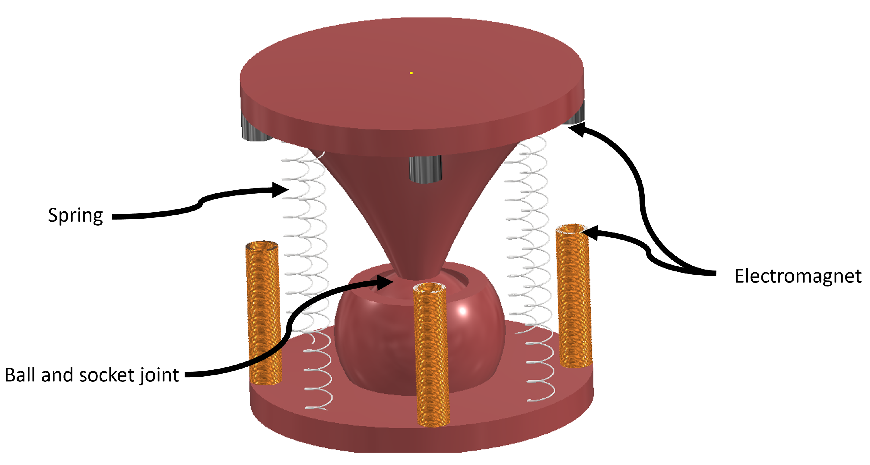
As illustrated in
Figure 2, each segment has a number of springs and a number of electromagnets. The forces must be balanced between these parts. Fewer than 3 springs and 3 electromagnets reduce the available bending angles that the segment can achieve.
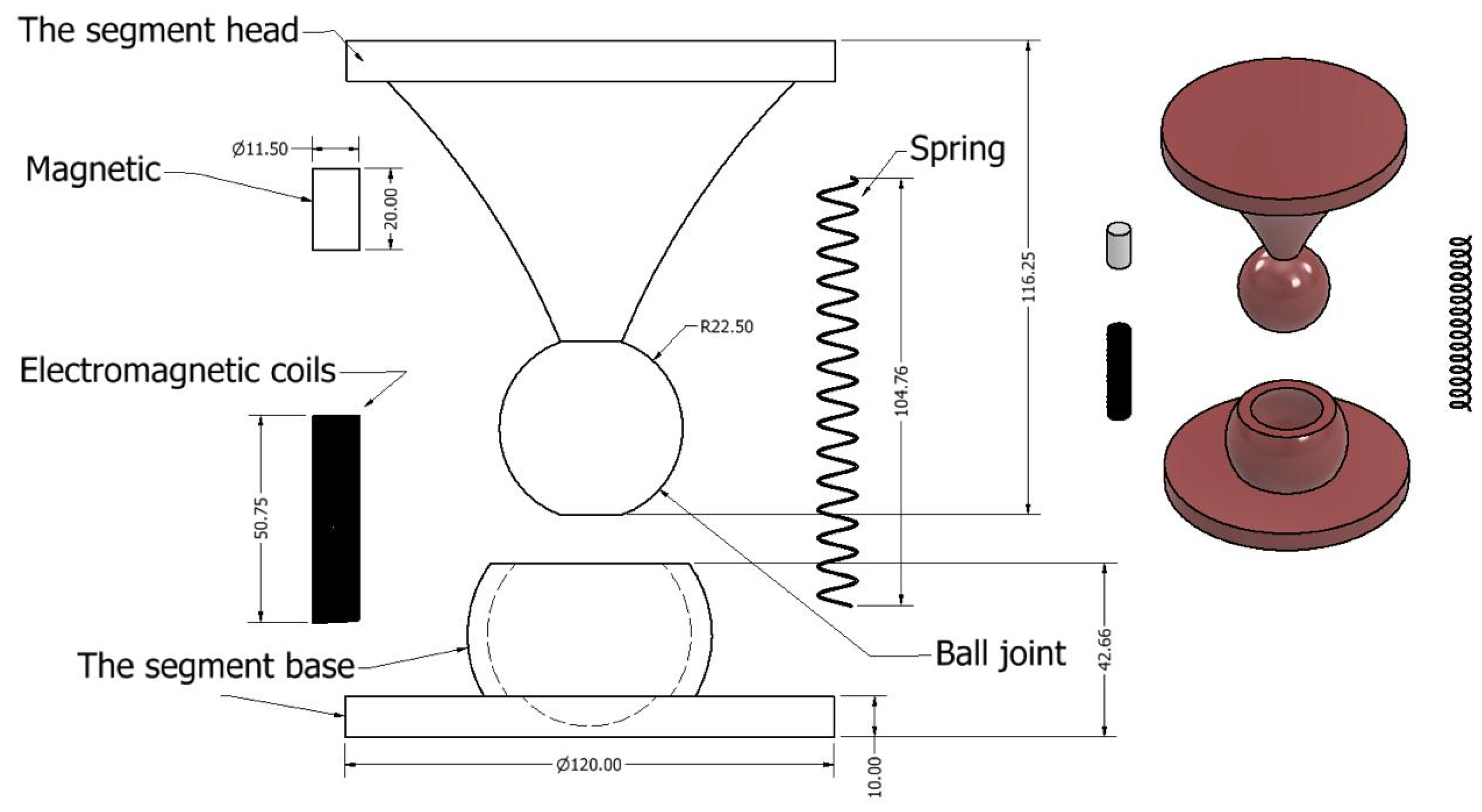
The assembled part for a single segment is shown in
Figure 2 and The disassemble part is described in the drawing shown below in
Figure 3.
3. Modelling and Kinematics
Fundamentally, there are two main forces that affect the net force
which is required to bend the segment into the desired angle. The first force is the magnetic force which is basically considered as an attractive force. The second force is the repulsive force from the spring
which is responsible for maintaining the equilibrium status of the segment once no other forces are applied, as described in Equation (
1).
-
i represents the number of coils or springs, ;
-
represents the force direction;
-
;
-
k represents the number of segments in the robot;
-
M represents the force of the electromagnets and S is the force of the springs.
So if we consider one segment of the report,
as shown in Equation (
2).
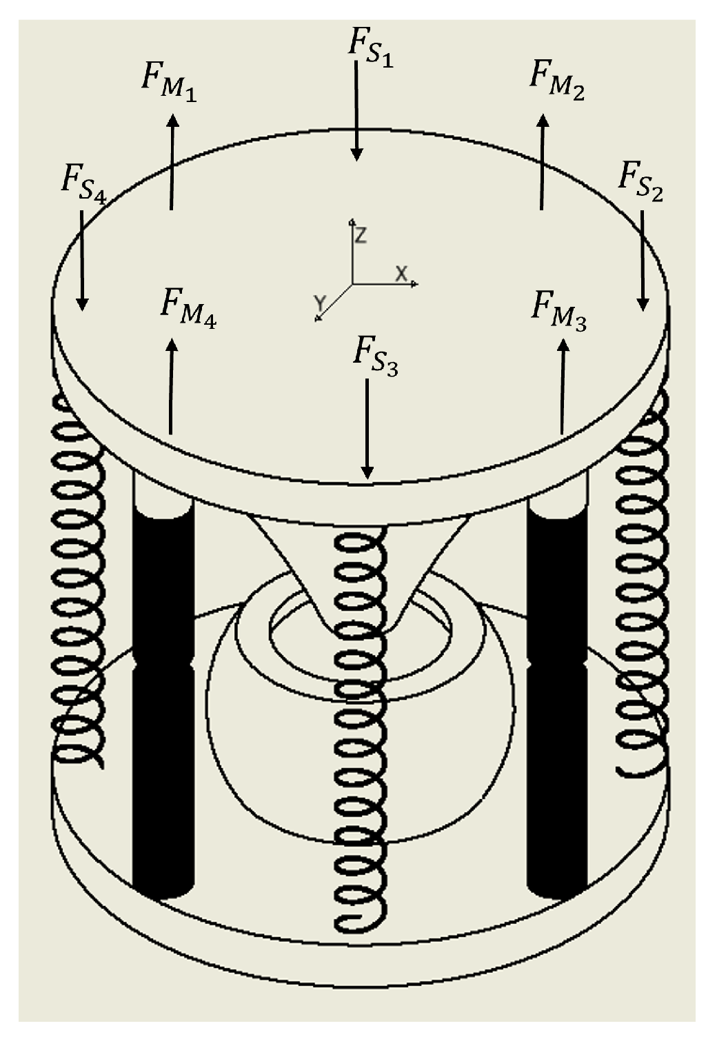
The direction of the forces for four springs and four electromagnets is shown in
Figure 4:
Thus, the equation for one segment, which has three axes to move in, is shown in Equation (
3):
Since the balancing force is the spring force, the input force of the electromagnet will be set according to the force of the desired deflection of the spring.
The magnetic force
consists of two main components. The first component is the force produced by the electromagnet
, shown in Equation (
4), and the other component is from the permanent magnet
. The force between the electromagnetic coil and the permanent magnet can be found with:
where
B is the magnetic flux density of the electromagnetic coil,
V is the volume of the permanent magnet
, and
is the magnetization of the
.
To find the magnetic field of the electromagnet, a cylindrical coordinate system
is introduced. As the electromagnet is azimuthally symmetric
, the magnetic field can be shortened into radial component
and axial component
as shown in Equation (
5):
Also, the electromagnetic field B produced by an electromagnet can be found as vector potential
, as shown in Equation (
6):
Then, by calculating the curl of the vector potential
,
and
can found, as shown in Equation (
7):
The magnetic vector potential for an electromagnet with radius
a, a number of turns per unit length
n, current running in the electromagnet
i, and permeability can then be expressed as Equation (
8):
where
r and
z are the radial and axial distances,
, and
L is the length of the electromagnet. The electromagnetic field components
and
can be found using Equation (
9) and Equation (
10), respectively:
Based on the above equations, the total electromagnetic field of each electromagnet is
and the direction angle
is
. The electromagnetic field can then be calculated precisely at any chosen point
by using the finite element method (FEM) or the above equations. However, it is important to know that the design is restricted to move only in the axial direction. Hence, the calculation for the magnetic field will be considered only for the axial component.
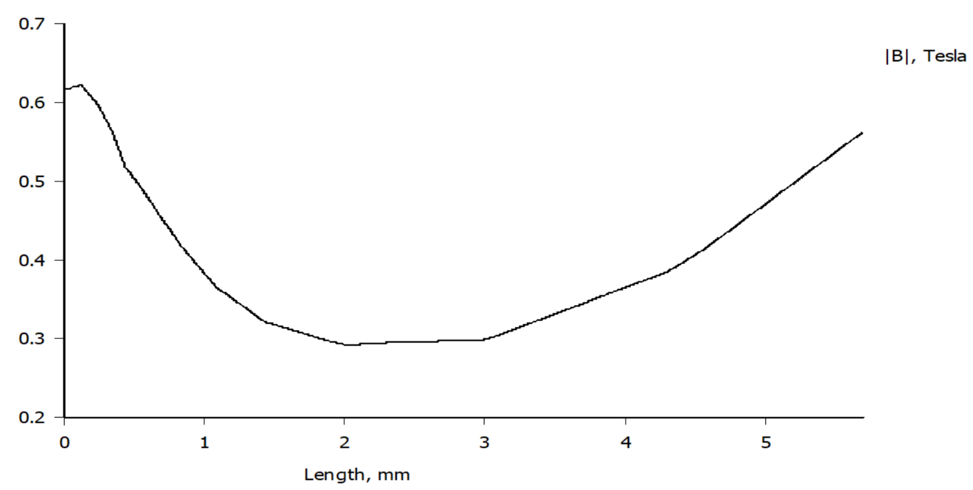
Figure 5 shows the simulation of the magnetic field between electromagnet and PM whereas
Figure 6 shows the magnetic field patterns on a permanent magnet with its magnitude and direction using the finite element method.
It is more suitable to adopt the above equations due to the sudden changes in the parameters of the segment and in case of real-time implementation. A favourable way to eliminate the computation effort is to define the magnetic field produced by the electromagnet by means of the current running through as the relationship between them is linear. Nevertheless, in this system, an iron core is presented in order to enhance the magnetic field, which makes the relation between the magnetic field and the current nonlinear.
There are several mathematical methods to estimate the magnetization of the iron core; however, these methods are either imprecise or excessively complex. In this work, numerical data provided by the core manufacturer were used in an analytical approach as a lookup table combined with piecewise linear approximation to calculate the magnetization of the electromagnet core at any specified current.
As shown in the 3D design, each segment can consist of four electromagnets. When bending the segment at any chosen angle, one of the electromagnets will produce an attractive force and the opposite electromagnet will produce a repulsive force. As a result, two main forces will contribute to the bending mechanism each time, such that
. In the case of the bending angle between two electromagnets, the contribution of each electromagnet depends on the bending angle
, such that the total magnetic field will be shaped to the required direction. The resulting dynamic magnetic force can be found as the sum of the static field components applied to the PM, as illustrated below:
where
is the magnetization component of the PM, and
is the axial magnetic field of the individual electromagnet applied to the PM.
The other part of the force which achieves the balance and rotates the segment to the desired angle are the spring forces, as described in Equations (
1) and (
2). The spring repulsive and attractive forces can be represented by Equation (
12); these springs are placed to stabilize the system and return it to the balancing phase.
and the deflection
y is represented by Equation (
13):
where the parameters are
G = modulus of rigidity;
d = wire diameter;
D = mean spring coil diameter; and
N = number of active coils; and the equation can be reduced by using the scale of the spring
k, which is described in Equation (
14):
And the new version of the equation is
or
in the case of compression, and
or
in the case of extension.
If there is no force in
or
, the force of the spring will be calculated as shown in Equation (
15):
If the spring parameters are fixed, assuming that the spring will not create any shear force at the base of the spring at both ends, the force is normal to the base. But it has two angles depends on the segment rotation in 2D motion. So the equation will be as described in Equations (
16) and (
17). The distances that the angles create are shown in
Figure 7.
Thus, the robot’s desired angles will be chosen by the operator, and then the force of the spring can be calculated. And by placing Equation (
19) into Equation (
3) with the substitution of all the known terms from the electromagnetic forces, the current input can be calculated to bend the segment into the desired angle. In the end, the input is going to be the angle and the output is the current value.
4. Movement Analysis
This section presents a proof of concept for the bending mechanism of a single robot segment. At the system level, the segment has a single input—the desired bending angle—and an output, which is the current needed to achieve that angle. This current driven through the coil is designed to generate either a repulsive or attractive electromagnetic force relative to the permanent magnet. This magnetic interaction disrupts the segment’s initial force equilibrium, governed by Equation (
3), where the forces of the spring and permanent magnet are balanced in a neutral state. And their behavior can be represented by Equations (
11) and (
19) for a single segment for proof of concept.
When one of the coils shown in
Figure 3 is active, the segment’s equilibrium forces shown in Equation (
1) will be disrupted or imbalanced to create more force at a specific angle of interest. This imbalance creates an angle of interest that causes the segment to bend in a particular direction based on the position of the active coil and polarity. When the bending angle increases, the current increases in the active coil and vice versa. This relationship ensures that the bending mechanism is responsive and precise, with fine adjustments to the current enabling accurate control over the angle.
As the segment bends, its radial position changes due to the angle adjustment. As shown in
Figure 8, the radial distance component also rises based on the change in the angle of motion. Moreover,
Figure 8 shows the variations in the angle by around 60 degrees, which can cause a radial shift of the segment by around 0.8 cm.
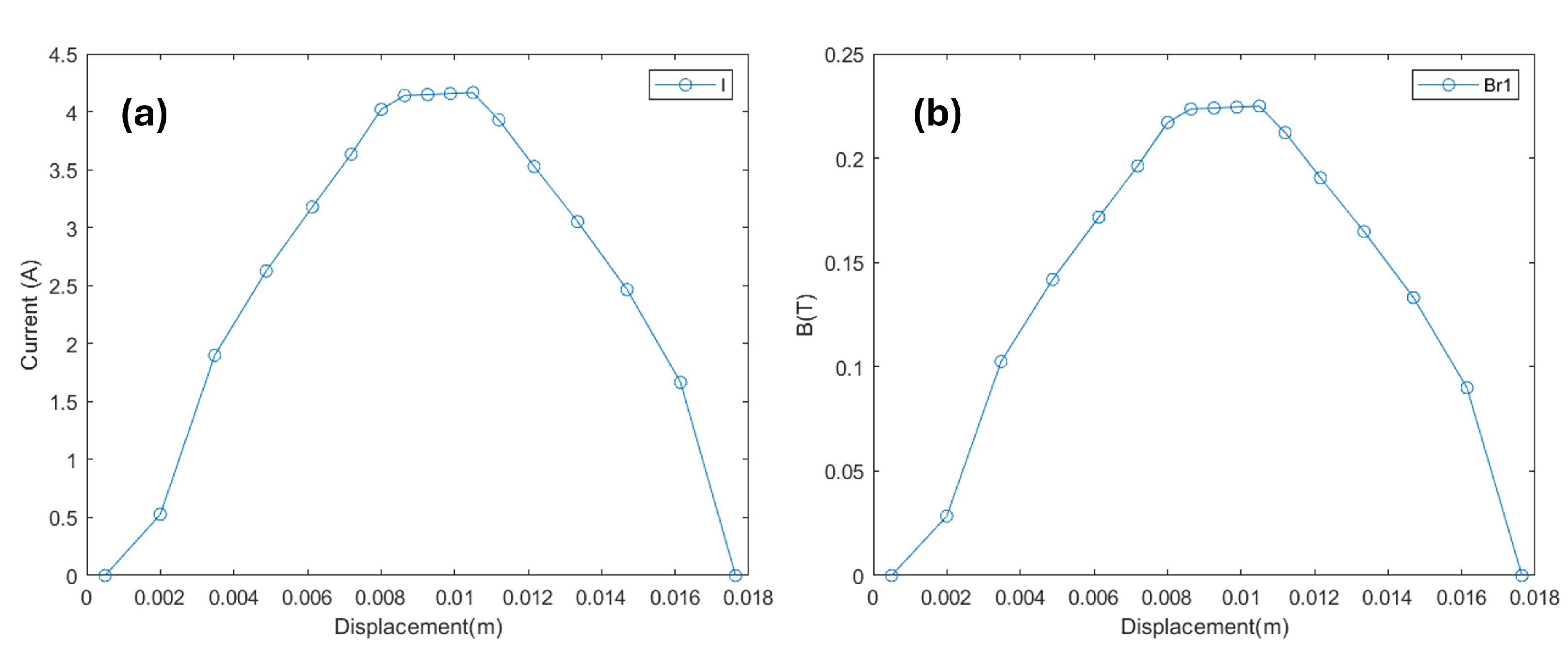
The current and electrical flux density required to opt for this bending in this segment are depicted in
Figure 9. Both of them rise if the angle increases. For the system to achieve this 60-degree bend, a current of approximately
is needed in the active coil, as illustrated in
Figure 9. Additionally, this amount of current passing through the coil will generate around
. This increase in current and flux disrupts the balance between the electromagnetic force, the permanent magnet, and the spring, creating the extra force needed for bending.
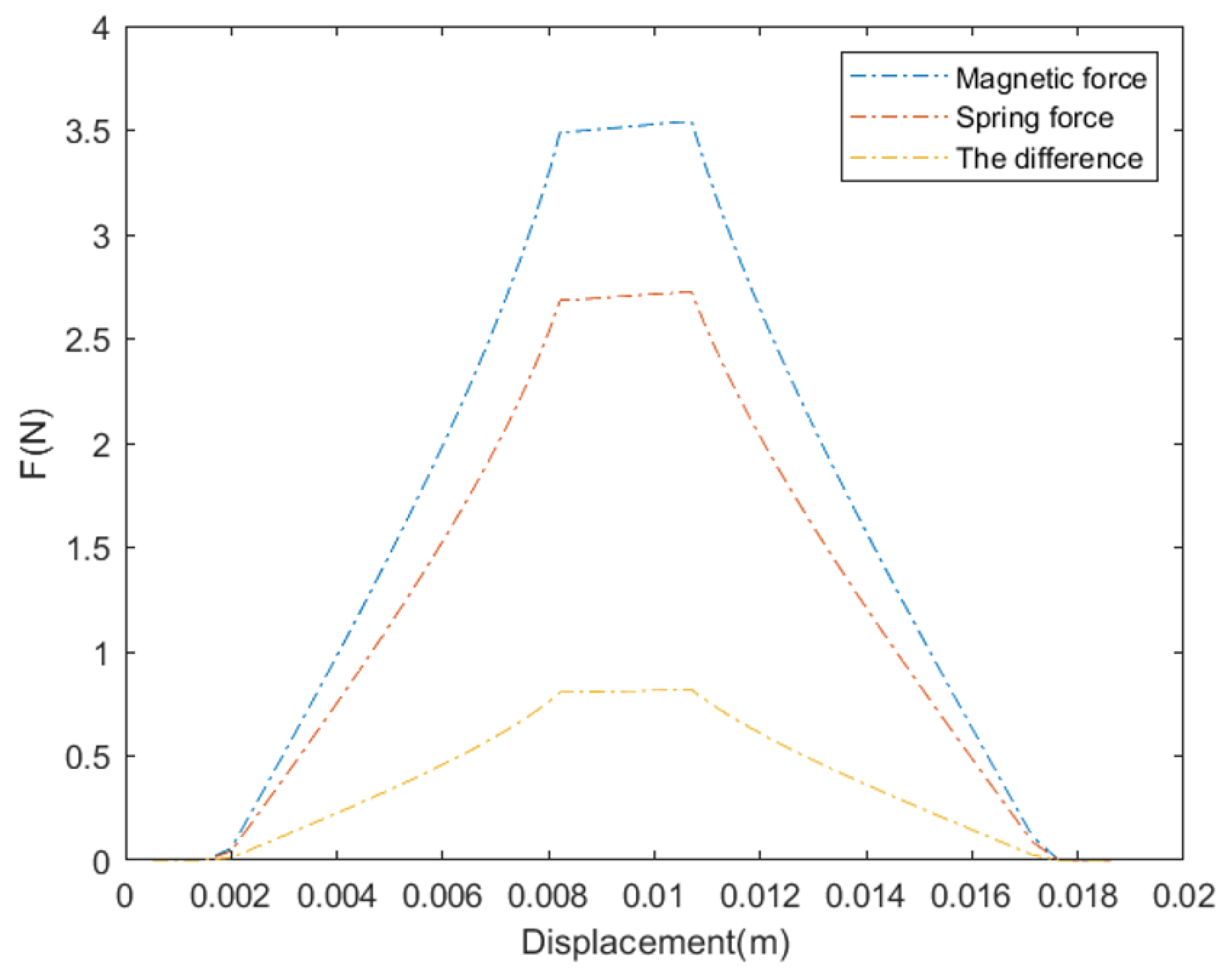
Figure 10 shows the magnetic force between the electromagnet and the permanent magnet, which acts opposite to the spring force with a margin of
. It also shows the difference between them, creating the desired angle in the segment. It can be seen that as the angle increases, the required magnetic force increases. In
Figure 11, we can observe the direction and amount of movement in both the radial
and vertical
directions. Here, the step size in the radial direction is noticeably larger than that in the vertical direction, suggesting that most movement occurs horizontally, which could be important for overall stability and positioning.
In summary, this analysis demonstrates how the bending mechanism in a robot segment relies on precise interactions between magnetic and spring forces to achieve controlled movement. By adjusting the current in the coil, the system generates the magnetic force needed to reach a specific angle, with each increase in angle requiring proportionately more force and current. The combined effects of magnetic force, spring tension, and radial displacement provide the control and stability essential for accurate bending. This proof of concept offers a strong foundation for understanding how to achieve precise angular adjustments in robotic applications.


 ,
, 