Article

Design and Verification of a New Fixture for Machining of Porous Blocks for Medical CAD/CAM Systems

Faculty of Technical Sciences, University of Novi Sad, Trg Dositeja Obradovica 6, 21000 Novi Sad, Serbia
*
Author to whom correspondence should be addressed.
Appl. Sci. 2025, 15(2), 794; https://doi.org/10.3390/app15020794
Submission received: 28 December 2024 / Revised: 10 January 2025 / Accepted: 13 January 2025 / Published: 15 January 2025
(This article belongs to the Section Biomedical Engineering)

Abstract

:
This paper presents a new innovative approach for designing and manufacturing a fixture for locating and clamping porous blocks of biocompatible material, which is required for their machining on CNC machines. Manufacturing porous blocks for their application in medical and/or dental fields is gaining traction. However, limited solutions are available today. In order to address this issue, a new design has been proposed for locating and clamping porous blocks. Finite element analysis was used as a verification tool for the designed fixture with the workpiece, which showed a low concentration of stresses. After the manufacturing, dimensional verification in the form of CAD analysis showed small deviations on the manufactured object with deviations peaking around +0.015 mm, thus validating the adequate locating and clamping of the workpiece.

1. Introduction

Taking into account the rapid technological development that is primarily focused on production with maximum efficiency and minimum costs, the role of fixtures today presents one of the key elements in this whole process [1,2,3]. Their primary role is the accurate locating and clamping of objects in defined working positions during the various processes that take place, such as machining, measurement, etc. [4,5]. Therefore, their dynamic behavior has a direct impact on the accuracy, quality, and cost-effectiveness of the machined workpiece [6,7]. By being able to provide several key advantages, such as automation of many different tasks, speed-up production times, increasing precision for performing tasks with a higher degree of accuracy and precision, and allowing flexibility for handling a range of different tasks, fixtures today present production equipment which can contribute to an efficient production process [8]. However, with the natural progression of these fixtures through their adaptability and flexibility that they provide, in addition to their standard use in the machining industry, their application has also been extended to other sectors such as medicine, dentistry, etc. [9,10,11]. Also, the application of finite element method (FEM) analysis has a wide use today, and as such, has found its way into medical applications as well, such as dentistry [12,13], maxillofacial [14], or cranial reconstruction [15]. By providing numerical results in a virtual environment, they are providing an immense contribution towards a better understanding of how different processes behave under certain environments.
Biocompatible porous blocks (also referred to as scaffolds) can be made using several different techniques such as solvent casting/particle leaching, thermally induced phase separation (TIPS), electro-spinning, gas foaming, and additive manufacturing [16,17,18,19]. Machining of various reconstructive anatomy such as grafts or implants from these small to medium size biocompatible porous blocks still presents a challenge, as they are usually manually shaped. However, this drawback has some limitations regarding the complexity of the implant that can be shaped, but also adequate fit of the shaped implant to the site. The application of CAD/CAM systems eliminates this drawback, as virtually any shape can be manufactured while maintaining the perfect fit between the graft/implant and the recipient site for improved integration [20,21]. The application of fixtures in the field of medicine today includes their wide application in surgery, diagnostics, rehabilitation, and for research purposes as well [22]. In each of these areas, fixtures have become a key factor in achieving high standards of accuracy and success in various medical procedures. While in rehabilitation, fixtures enable the stabilization and support of different orientations [10], they have also found their use in virtual environments where haptic virtual fixtures (VFs) are being used for force feedback mechanisms that enhance human performance, increase accuracy, and reduce the time taken to perform certain tasks [9]. Design of the personalized stereotactic fixture is also developed which is being used for implanting depth electrodes in patients where it allows surgeons to precisely guide instruments and reduce patient trauma [23]. Other applications of fixtures are also for manufacturing parts with thin ends (like the hip joint) by providing support during machining [24]. They are also being used for optimization tasks in cranioplasty [25], and when it comes to the production of medical equipment fixtures have been also used for the production growth of different medical equipment as well [11]. With the rising use of additive manufacturing (AM) technologies, additively manufactured fixtures for bone measurements are also being developed [26], as well as for the treatment of amputees [27]. In addition, fixtures also play a critical role in many medical tests such as providing sample stabilization [28], sample handling [29], setting consistent test conditions, and accurate load placement [30]. These various tests are essential for understanding the biomechanical properties of bones, muscles, tendons, and joints, which further contribute to the development of more effective therapeutic approaches and medical devices. The use of appropriate fixtures in medical testing is key to ensuring accurate test results and guaranteeing their functionality in real-world conditions.
As can be seen, although today there are various applications of fixtures in the medical field, their application is still somewhat limited and narrowly specialized to specific uses where the focus is mainly put on testing purposes. Fixtures are widely used in many fields, including medical applications, but their design is typically tailored for rigid and durable materials, leaving a significant gap in addressing the needs of fragile, porous materials. Porous biocompatible blocks, due to their delicate structure, are prone to breakage under excessive force, making traditional fixture designs unsuitable for machining such materials. This limitation significantly restricts the potential of CAD/CAM systems for manufacturing complex, patient-specific implants. Current research on fixtures primarily focuses on their applications in testing, diagnostics, and rehabilitation, with little emphasis on adapting them for machining sensitive materials. This presents a critical challenge on how to securely clamp and position porous materials for precise machining while preserving their structural integrity.
To address this challenge, this study introduces a novel fixture specifically designed for machining porous biocompatible blocks. Unlike traditional fixtures, which are optimized for rigid materials, this fixture applies minimal force to securely clamp and position the porous material without causing damage. The design incorporates silicone tabs to enable soft clamping, further reducing the likelihood of damage during the machining process. The fixture also integrates seamlessly with CAD/CAM systems, facilitating the precise machining of osseous materials. This approach opens new possibilities for machining delicate biocompatible materials in medical applications. Porous bone blocks, due to their sensitivity and delicate porous structure, can easily break. Excessive force risks compromising their integrity, often rendering them unusable. The fixture proposed in this paper specifically targets these challenges, combining minimal clamping force with advanced design features to preserve the material’s structure during machining. By addressing these limitations, this innovative solution expands the possibilities for safely machining fragile biocompatible materials, ensuring both precision and material integrity in medical applications.

2. Methodology

For machining on dental 5-axis CNC machines, today exists a standard size disc with fixed diameter of Ø98.5 mm, and a thickness varying from 10 mm up to 25 mm. The discs are made from various different materials such as titanium alloy, zirconia, chrome cobalt, polymethyl methacrylate (PMMA), polyether ether ketone (PEEK), and wax, which are used for various purposes. Based on these materials, tool cuts out the desired shape while the disc is placed inside a CNC machine holder.
However, porous bone blocks do not come in this size, since their machining would not be feasible if they are made as large circular discs. The reason for this is that they would be structurally unstable and break due to their large shape, size, and fragility. Additionally, the size would lead to inefficiencies in material utilization, as large portions of the disc area would remain unused. Today, porous blocks come in rectangular and cubical shapes, depending on their use case. Porous block from SmartBone® (Industrie Biomediche Insubri SA, Mezzovico-Vira, Switzerland) was used in this study. It is a bovine bone-derived mineral matrix with resorbable biopolymers and cell nutrients that presents a chemical structure and a morphology resembling human bone. With its 27% open porous microstructure, it mimics the human bone. However, its physical properties have a rigid but not elastic structure, which makes it fragile and thus difficult for machining operations [31]. In that regard, the idea for fixture design was developed in order to use the standard disc shape, as a holder for rectangular porous block placed inside it, where it would be located and clamped for machining on CAD/CAM system. Depending on the size of the porous block from different manufacturers, multiple discs can be prefabricated and equipped with clamping fixtures facilitating this design, in order to expand their versatility. Figure 1 shows the basic workflow of the whole process. It consists of several key steps, and those are fixture design, FEM analysis, fixture manufacturing, fixture testing, and dimensional verification.
In the first step, based on the shape of the porous block, a novel fixture was designed from a circular disk, in order to be able to locate and clamp the required shape. For this purpose, SOLIDWORKS v2018 (Dassault Systèmes) software was used. Key design features, such as clamping mechanisms and support structures, were modeled to ensure proper alignment and interaction between components. When designing a fixture, several objectives and requirements must be addressed to ensure its functionality, efficiency, and suitability for the intended application. Ensuring that fixture maintains correct positioning and alignment of the workpiece throughout the operation minimizes dimensional and geometric errors. Also, it needs to provide sufficient structural strength to resist deflection, vibrations, and any forces that occur during workpiece machining. It needs to accommodate easy tool access while clamping mechanism does not obstruct machining process. By meeting all these objectives and requirements, a fixture can significantly enhance process efficiency, accuracy, and product quality. However, it should be noted that specific quantitative thresholds for some design objectives, such as allowable deflection or clamping force, could not be established due to the absence of standardized benchmarks for fixtures designed to handle porous materials. Instead, the validation of these objectives was carried out through FEM analysis and qualitative assessment, ensuring the fixture meets practical and functional requirements for machining delicate porous blocks.
With all this in regard, when developing the design concept of fixture for clamping and positioning of porous blocks, special attention was paid to its simplicity and ease of placing and removing blocks from the fixture while providing uninterrupted tool access, and without any obstructions during machining process. Clamping of these porous blocks should be conducted in way that firmly clamps the required shape in place, while not using excessive force, in order to prevent any possible damage to them.
With all these requirements and objectives in regard, Figure 2 shows the whole design process of the new fixture. Regarding the workpiece, a porous block of 50 × 40 × 10 mm and a standard disc of Ø98.5 mm and thickness of 10 mm were used for this study (Figure 2a). From Figure 2b it can be seen that the design process involved a rectangular cut-out in the disc that would facilitate the porous blocks insertion. This inner shape depends on the porous block size, in this case, it is 51 × 41 mm for the block used in this study. An edge clearance was incorporated into the design that ensures compatibility with specific block dimensions. A clearance of 0.5 mm on each side was left on the inner rectangular shape of the fixture body where the porous block would be inserted, which results in its dimensions being 51 × 41 mm. This clearance was specifically added to address potential tolerances in the porous block’s fabrication process, which can occur due to the inherent challenges of manufacturing highly porous materials.
Regarding the further design, four 3 mm holes were drilled in disc that would allow fixation of two steel plates (1 mm thickness), which were designed as well with cut-outs in them, and with chamfered (10 × 10 mm) inside edges (Figure 2c). These chamfered edges allow placement of silicone tabs (10 mm in diameter and 1.5 mm thickness), which will support the bone block fixation. Also, four M3 × 18 mm pan head slotted screws were used to mound and fix the steel plates and the porous block between them. A total of eight silicone tabs were placed (four on each side) for porous block clamping, which will enable a much softer contact preventing any possible damage to the block during its locating and clamping in the fixture. Completely designed fixture is shown in Figure 2c.
In the second step, FEM analysis was conducted in order to verify the fixture’s design functionality where different stress loads are applied to the porous block. The focus of FEM analysis was on the behavior of porous block during its clamping and machining on CAD/CAM system, in order to verify its stability and fixed location during workpiece machining. FEM analysis was conducted on porous block workpiece for Von Mises stress, displacement, and strain under three different preloads of 10 N, 35 N, and 50 N, respectively.
Regarding the predefined conditions for FEM analysis, entire fixture body (from PEEK material) has been defined as a fixed rigid body. Silicone tabs in contact with the porous block have defined pressure on the porous block body. Also, fixed geometry of the porous block has been defined on its surrounding surfaces, limiting its potential movement as well. External load, i.e., force, has been defined on top surface of the porous block (simulating the machining of bone graft in that region). Also, no penetration contact was defined for all components of the fixture (Figure 3a).
In order to verify the accuracy of the FEM analysis, a mesh independence study was performed for the porous block. Figure 3b shows the plotted results of the mesh independence study used to select the optimal size of the FE model for the porous block. The conducted mesh convergence study confirms that the FEA model has converged to a solution, justifying mesh independence. Based on this, the mesh for the bone block consists of a total of 97,459 tetrahedral elements and 139,616 nodes (corresponding to an element size of approximately 1.08 mm), which will be used for the FEM analysis (Figure 3c).
Based on a literature review [31,32,33], and according to [32], expected force applied to the bone block was 35 N, but considering the possible variations in machining conditions, this FEM analysis was conducted under three different static preloads of 10 N, 35 N and 50 N in order to test porous blocks stability during machining. The properties of synthetic bone block material were based on [31,32], while other material properties were selected from the SOLIDWORKS database. The reason for choosing steel 316 as a material for steel plates was because it has found its use in medical industry for its good properties and resistance to corrosion. The mechanical properties of materials used for this FEM analysis are shown in Table 1.
Third step involved manufacturing the fixture, based on its design. For this step, a rectangular 51 × 41 mm shape and appropriate holes, according to the design, were machined on GU 600 (INDEX, Esslingen, Germany) CNC machine from a PEEK disc. PEEK disc was used because it is strong and resistant material with small weight and its ability to absorb loads (density: 1.52 g/mL, stress at yield: 110 MPa, tensile modulus 5100 MPa, tensile elongation at break: 5%, flexural strength: 178 MPa and flexural modulus: 4800 MPa). Two steel plates were also cut in required shape from 1 mm stainless steel sheet on a UNIJET PJ5AX (PTV, Hostivice, Czech Republic) waterjet machine.
Fourth step involved testing the fixture with the workpiece on a 5-axis CNC milling machine. A custom-designed 3D model of bone graft was selected as a test object (Figure 4). Bone grafts are used today as a bone substitute in oral surgery applications, and as such have a very complex and irregular shape, due to them being designed for each patient personally. And its machining, due to its complex shape, presents a challenge.
Dental CAD/CAM system CC Power (INTERDENT, Celje, Slovenia) was used for machining of porous block equipped with MillBox CIM software. Appropriate machining strategy using Strategy Editor within MillBox CIM software was selected. This involved defining several steps. First, appropriate CNC machine was selected, in this case CC power machine. Next, block holder was selected which will hold the designed fixture in place. Regarding the toolset selection, long tools were selected. For material that will be machined, and since porous block material was not available in the software database, PEEK was selected. Regarding the restoration type, since this is a filter to select among the several restoration types inside MillBox CIM software (crown, bridge, coping, inlay, and outlay), inlay was selected because bone grafts are not available in the software database, and inlay presents the freeform shape. A total of 6 operations were performed during machining. Cutter material, which is made of titanium, was used for all operations. External rough milling (on both sides) was performed using end mill with 2 mm ball tip diameter, external finish milling (both sides) was conducted using end mill with 1 mm ball tip diameter, and profile milling and connectors reduction were completed using end mill with 0.6 mm ball tip diameter. Feed rate varied, depending on the specific operation, and it was 1200 mm/min for rough milling, 1000 mm/min for finish milling, 500 mm/min for profile milling, and 600 mm/min for connector reduction. Spindle speed was constant for all operations, and it was defined at 1000 rpm. Length of all mills used is 50 mm. CNC milling parameters are shown in Table 2.
As a final step, dimensional verification was performed in order to verify the accuracy of the machined workpiece test part. This was performed in order to verify that the manufactured bone graft satisfies the required conditions regarding its accuracy. It was measured using CMM Contura G2 by CARL ZEISS, Oberkochen, Germany (MPEE = (1.9 + L/330 μm), equipped with ZEISS VAST XXT scanning probe and CALYPSO v4.8 measurement software. A measurement stylus with 1 mm diameter was used, and scanning strategy was applied, which consisted of narrow grid pattern where the resulting points were obtained and then mesh 3D model was reconstructed from it. CAD Inspection analysis was performed in GOM Inspect v2019 software in order to analyze 3D geometrical deviations.

3. Results

In regard to the current design of the fixture, FEM analysis was conducted. Figure 5, Figure 6 and Figure 7 show FEM analysis results for Von Mises stress, displacement, and strain under three different preloads of 10 N, 35 N, and 50 N, respectively.
Regarding the analysis, it can be seen that the stress analysis for the 10 N load is not very significant (4.856 × 10⁻² MPa), however, some stress concentrations were found on the porous block on 35 N and 50 N load, and they are 1.700 × 10⁻¹ and 2.428 × 10⁻¹ MPa, respectively. This is noticed on the longer edge of the porous block inside the fixture (Figure 5). The resulting displacements (Figure 6) show that most of the displacement occurs at the center of the bone block, as expected, due to the concentration of forces there, it equals 1.269 × 10⁻⁴ mm and 1.813 × 10⁻⁴ mm for 35 N and 50 N, respectively. Insignificant displacement is noticed for the 10 N load, which was 3.627 × 10⁻⁵ mm. Strain analysis for all three sets shows similar trend results of 2.344 × 10⁻⁶, 8.203 × 10⁻⁶, and 1.172 × 10⁻⁵ for 10 N, 35 N and 50 N, respectively (Figure 7).
It can be observed that with the increase in static preloads for all three different sets (10 N, 35 N, and 50 N), stress, displacement, and strain values are rising proportionally. Based on the detailed view, minor red areas were noticed on the longer edge of the porous block for stress and strain. By comparing the obtained results with the actual material’s known stress limits in [34], it is concluded that the stress concentrations found in the FEM analysis, which reach a maximum of 2.428 × 10⁻¹ MPa (for the 50 N load), do not approach critical levels. These values are significantly lower than the material’s maximum stress capacity, ensuring that the porous block remains well within safe limits. Therefore, the stress concentrations observed in the analysis are unlikely to cause failure or excessive deformation of the porous block, confirming the structural integrity under the applied loads. On the basis of these results, it can be seen that FEM analysis showed overall good results, with low distribution of stress and low displacement in the XYZ direction. This showed that the selected design should perform as intended and that it will support the porous block during its machining.
After the FEM analysis, the next step involved manufacturing the designed fixture in order to test the concept and functionality of the device. According to the design, a PEEK disc with a fixed diameter of Ø98.5 mm, and a thickness of 10 mm was used for manufacturing the fixture, along with steel 1 mm plates, silicone tabs, and all necessary fasteners. A fabricated and assembled fixture is shown in Figure 8.
After the fixture has been fabricated, the next step involves testing in real conditions. Based on the requirements, a 3D model of bone graft was imported into MillBox CIM software, and a predefined machining strategy was selected by an operator. The only thing that was reduced from the predefined strategy was the spindle speed, due to the fragile nature of the workpiece, in order to prevent any breakage during CNC manufacturing (Figure 9a–c).
Figure 9a shows the locating and clamping of the workpiece inside the fixture and fixture placement in the disc holder of the INTERDENT CC Power CNC milling machine. Figure 9b shows the machining process. During the machining process, the disc holder was rotated by 180° for machining of the workpiece from both sides, in order to obtain the full shape of the final bone graft. Also, water was used to wash away the debris during machining. Figure 9c shows the machined bone graft from the porous block. The machining process of bone graft from the porous block was supported by four 3 mm pins during machining (Figure 9c).
After the machining of the bone graft was completed, the following step was to remove it from the porous block and clean it up. Figure 10 shows the manufactured bone graft and its placement on the 3D-printed upper jaw, for which it was originally designed. This step presents a quick verification that the manufactured graft actually fits in its designed place.
Dimensional verification was conducted as the last step in order to verify manufactured bone grafts dimensional accuracy and also to check if any deviations occurred, such as accidental movement of the porous block during its machining, which would impact its accuracy. CAD Inspection analysis was performed. Figure 11a shows the measurement process of bone graft on a CMM where the inner side of the manufactured bone graft was 3D scanned. The bone graft was placed on a putty material, which was shaped based on its geometry, and this enabled the bone graft to maintain a fixed position during CMM scanning. Figure 11b shows the measurement results (obtained point cloud and reconstructed mesh 3D model), while CAD Inspection analysis in GOM Inspect software is shown in Figure 11c.
On the basis of CAD Inspection analysis, it can be seen that the deviations are in the range of ±0.135 mm, while concentration is at around +0.015 mm. Some deviations in blue and red color can be observed as a result of material porosity. However, CAD Inspection provides sufficient information that the accuracy of manufactured bone graft is high, as these results indicate that the manufactured bone graft will provide a very good fit, which in return will speed up the whole surgical process and patient recovery.

4. Discussion

This study introduces and validates a novel fixture for machining fragile, biocompatible porous blocks, addressing a crucial challenge in the fabrication of medical and dental implants. The design integrates FEM analysis and experimental testing to ensure stability, accuracy, and material integrity during machining processes.
The FEM results in this paper demonstrated that stress and displacement within the workpiece remained within safe limits under preload conditions, even at the maximum applied force of 50 N. These results align with earlier studies emphasizing the importance of force distribution to prevent microcracks in brittle porous materials, as highlighted by [35,36]. Additionally, this study also supports [37], where FEM analysis was used to evaluate porous implants and underscored the importance of balancing structural stability and mechanical performance in biomedical applications.
Compared to more conventional fixtures that rely on rigid clamping systems [8,38], the proposed design effectively mitigates localized stress concentrations, which are known to compromise the material structure where clamping can also have an influence on geometric deviations as well [39]. Workpiece stability is of great importance during machining, and it depends on the clamping, especially when the porous materials are involved [40]. Functionally porous implants and their porous morphology, as discussed in [41,42], demonstrate the critical role of porosity in influencing the mechanical behavior of such materials. Considering that the primary component of porous implants, when they are machined to be porous, is that their mechanical properties are substantially lower than that of bone, this makes them difficult to machine [43]. The designed fixture in this paper addresses these issues by offering a more uniform force application, thus minimizing the risks of workpiece breaking during machining.
Experimental validation revealed minimal dimensional deviations (deviation range of ±0.135 mm, +0.015 mm at peak) thus being compliant with other conducted research on dimensional accuracy in this field [44,45,46]. This contributed to improved dimensional accuracy, emphasizing the application of used materials and their properties in achieving precise machining outcomes through the use of PEEK for its mechanical strength, while the flexibility and damping properties of silicone align with findings in [47] where a rubber-based fixture was developed for machining of low-stiffness parts and demonstrates how the viscoelastic and elastoplastic behavior of rubber-like materials effectively mitigates vibrations, enhances dynamic stability, and minimizes machining-induced deformation. This is very important when handling fragile materials.
Notably, the fixture’s hybrid design, balancing rigidity and compliance, sets it apart from traditional clamping systems. Rigid systems, while offering stability, can often induce surface damage or deformation in porous biomaterials [48]. The current fixture design overcomes these limitations by distributing forces more evenly across the surface, a critical requirement when machining biocompatible materials [49]. The focus on biocompatible materials’ machinability and the fixture’s adaptability reflects advancements in biomedical manufacturing technologies.
Also, while the clinical effectiveness of a customized 3D printed alloplastic bone material is still being studied, findings suggest that 3D printed customized bone graft materials could be used as an alternative for machining, but for more simple procedures, as it still needs further improvements [50,51].
Overall, this study advances the machining of biocompatible materials by presenting a novel fixture design that integrates FEM analysis and experimental validation to address challenges in the manufacturing of porous materials. This fixture demonstrates significant potential for enhancing the precision and reliability of CAD/CAM systems in healthcare applications.

5. Conclusions

Based on the results shown in this paper, it can be seen that the implementation of fixtures in the medical field provides numerous advantages, which in return aid in better healthcare. Application of FEM analysis proved to be useful for the numerical testing of new designs. In regard to the current design of the fixture for locating and clamping, it showed good results and the ability to be easily implemented for the fabrication of porous material.
Therefore, based on the obtained results, the following can be summarized and concluded:
  • Stress, displacement, and strain values were calculated for three different preload conditions (10 N, 35 N, and 50 N).
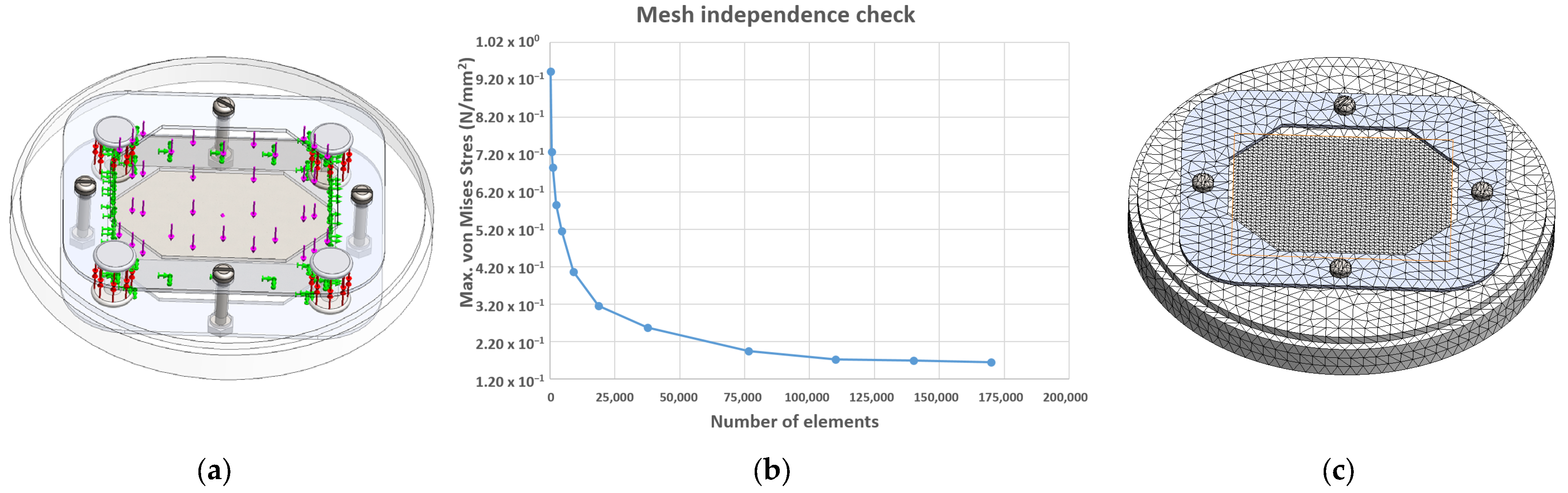
  • At 10 N load, the stress was 4.856 × 10⁻² MPa. For 35 N and 50 N loads, stress concentrations on the longer edge of the porous block were 1.700 × 10⁻¹ MPa and 2.428 × 10⁻¹ MPa, respectively.
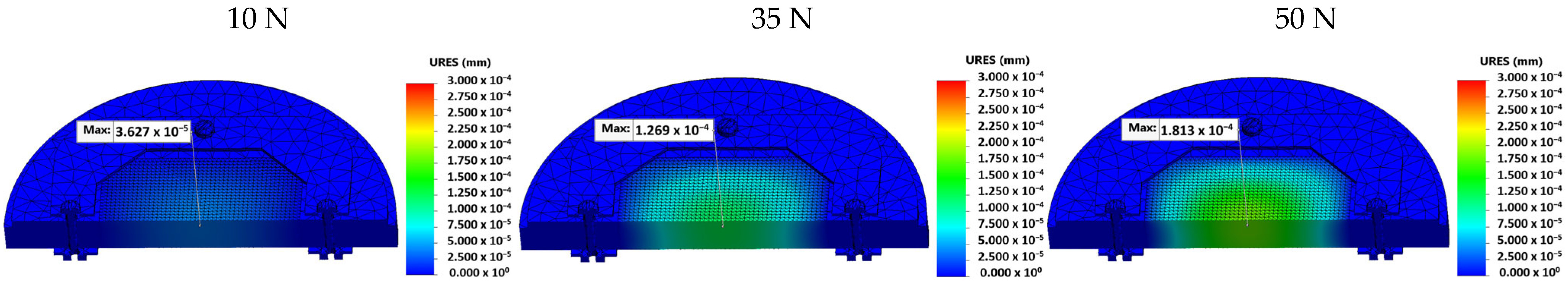
  • Displacement at 35 N was 1.269 × 10⁻⁴ mm, and at 50 N, it was 1.813 × 10⁻⁴ mm, while at 10 N was negligible (it was 3.627 × 10⁻⁵ mm).
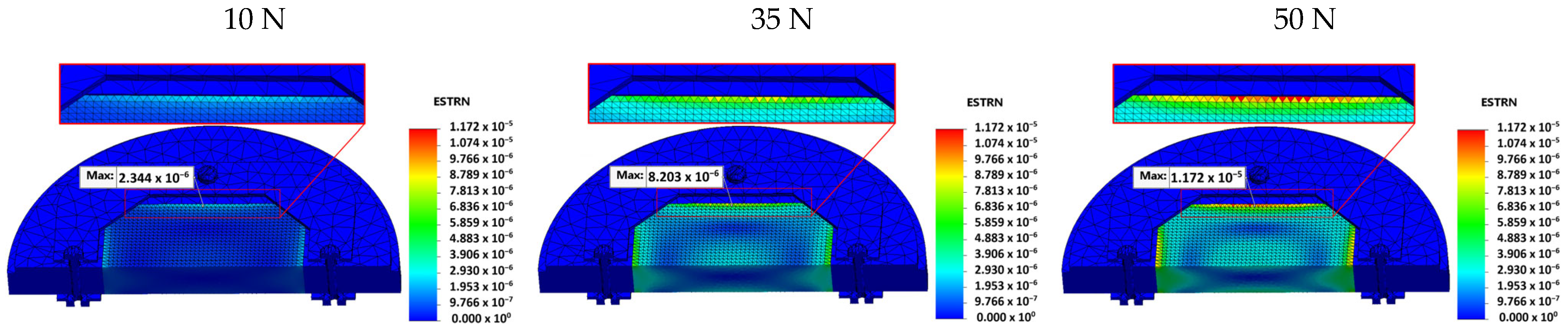
  • Strain values were 2.344 × 10⁻⁶ at 10 N, 8.203 × 10⁻⁶ at 35 N, and 1.172 × 10⁻⁵ at 50 N.
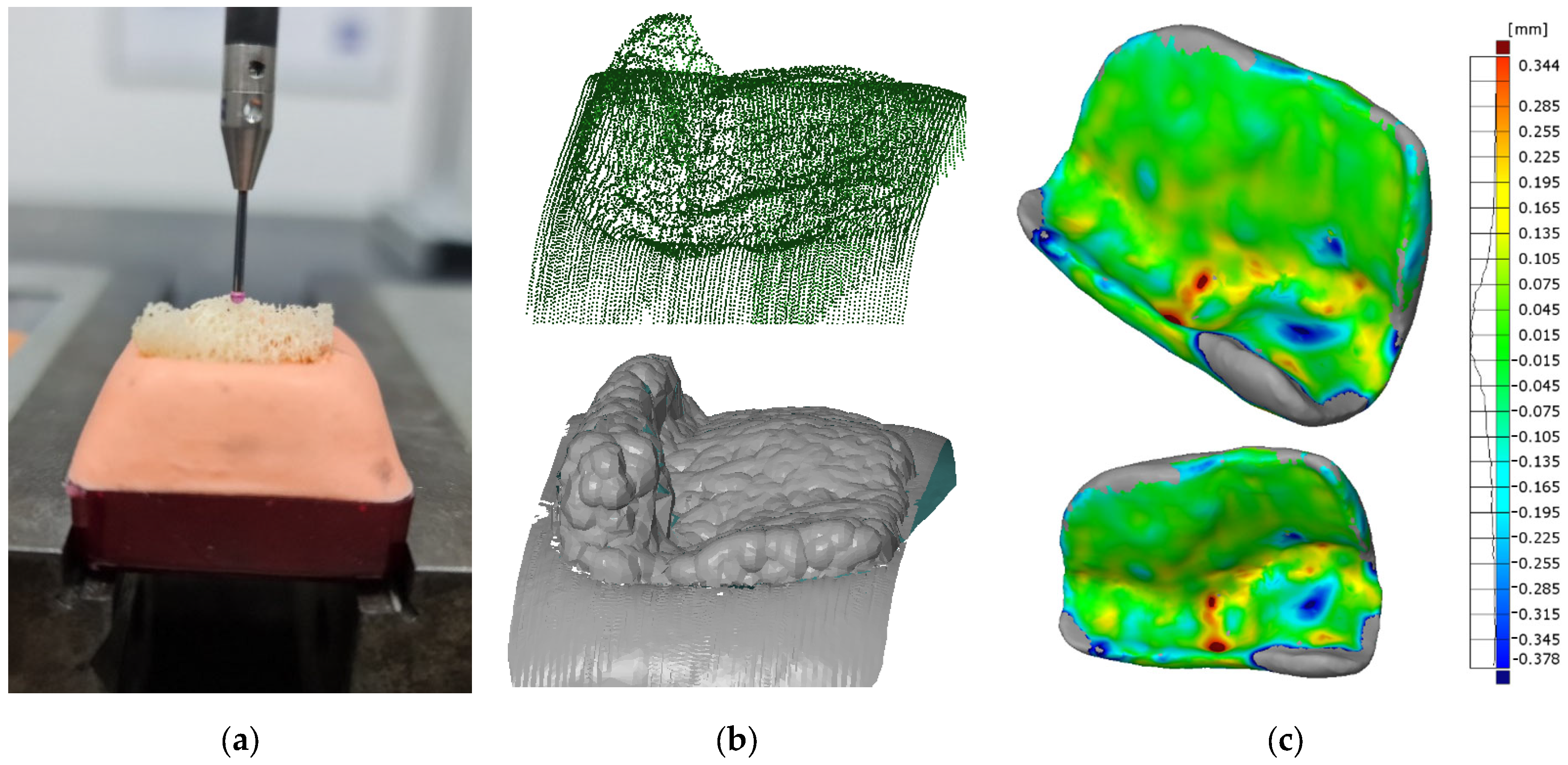
  • Dimensional deviations of the machined bone graft were found to be within the range of ±0.135 mm, with a peak concentration of +0.015 mm.
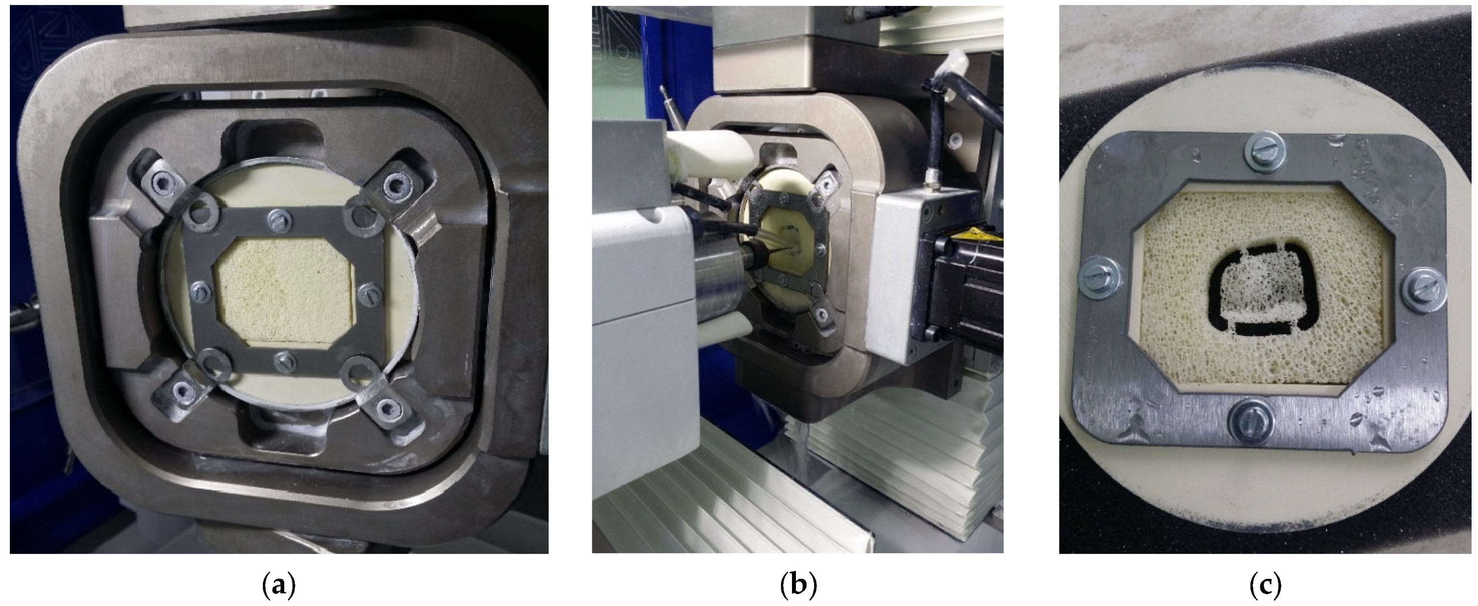
  • Clamping and machining performance showed that the fixture design reduced the risk of material breakage and deformation, ensuring stability during machining.
However, the designed fixture in this paper is optimized for specific block dimensions, which limits its versatility. Adjustable or modular designs could address this limitation, offering greater adaptability to varying sizes and geometries by enabling fixtures to be easily disassembled and re-assembled, depending on the dimensions of the workpiece. Future research will involve an upgrade to this design with added elements that would enable quick adjustment of the fixture to facilitate different shapes of porous blocks, thus eliminating the need to have different fixtures for each size of porous block. Furthermore, extending the current analysis to a wider range of biocompatible porous materials would enhance its applicability across diverse medical and dental use cases.
This continuous development and improvement of fixtures in medicine remains of vital importance for achieving the highest standards in the treatment of patients and improving their quality of life.

Author Contributions

Conceptualization, M.S. and I.B.; methodology, M.S. and D.V.; software, A.M. and Z.S.; validation, A.M. and Z.S.; formal analysis, D.V. and I.B; investigation, M.S. and D.V.; resources, M.S., D.V. and I.B.; writing—original draft preparation, M.S., A.M., Z.S., D.V. and I.B.; writing—review and editing, I.B. and D.V.; visualization, M.S. and A.M.; supervision, I.B. and D.V. All authors have read and agreed to the published version of the manuscript.

Funding

This research has been supported by the Ministry of Science, Technological Development and Innovation (Contract No. 451-03-65/2024-03/200156) and the Faculty of Technical Sciences, University of Novi Sad through project “Scientific and Artistic Research Work of Researchers in Teaching and Associate Positions at the Faculty of Technical Sciences, University of Novi Sad” (No. 01-3394/1).

Institutional Review Board Statement

Not applicable.

Informed Consent Statement

Not applicable.

Data Availability Statement

The original contributions presented in the study are included in the article material, further inquiries can be directed to the corresponding author.

Conflicts of Interest

The authors declare no conflicts of interest.

References

  1. Boyle, I.; Rong, Y.; Brown, D.C. A review and analysis of current computer-aided fixture design approaches. Robot. Comput. Integr. Manuf. 2011, 27, 1–12. [Google Scholar] [CrossRef]
  2. Gameros, A.; Lowth, S.; Axinte, D.; Nagy-Sochacki, A.; Craig, O.; Siller, H.R. State-of-the-art in fixture systems for the manufacture and assembly of rigid components: A review. Int. J. Mach. Tools Manuf. 2017, 123, 1–21. [Google Scholar] [CrossRef]
  3. Pandit, H.C. Jigs and Fixtures in Manufacturing. Int. J. Eng. Res. Appl. 2022, 12, 50–55. [Google Scholar]
  4. Chai, S.; Ouyang, L.; Bi, Q.; Yu, J.; Zhang, Y. An adaptive fixture for suppress vibrations and measuring workpiece deformation of thin-walled casings. Procedia CIRP 2021, 101, 322–325. [Google Scholar] [CrossRef]
  5. Bijelic, I.; Milovanovic, V.; Vukelic, D.; Simunovic, G.; Prica, M.; Sokac, M.; Tadic, B. Application of Natrium Silicate as a Phase Change Material in Fixture Design. Teh. Vjesn.—Tech. Gaz. 2023, 30, 465–473. [Google Scholar] [CrossRef]
  6. Feng, Q.; Maier, W.; Braun, S.; Möhring, H.-C. Dynamic modeling of the workpiece-fixture contact behavior for intelligent fixture design. Procedia CIRP 2023, 119, 58–65. [Google Scholar] [CrossRef]
  7. Vukelic, D.; Simunovic, G.; Tadic, B.; Buchmeister, B.; Saric, T.; Simeunovic, N. Intelligent design and optimization of machining fixtures. Teh. Vjesn.—Tech. Gaz. 2016, 23, 1325–1334. [Google Scholar] [CrossRef]
  8. Fiedler, F.; Ehrenstein, J.; Höltgen, C.; Blondrath, A.; Schäper, L.; Göppert, A.; Schmitt, R. Jigs and fixtures in production: A systematic literature review. J. Manuf. Syst. 2024, 72, 373–405. [Google Scholar] [CrossRef]
  9. Halabi, O.; Halwani, Y. Design and implementation of haptic virtual fixtures for preoperative surgical planning. Displays 2018, 54, 9–19. [Google Scholar] [CrossRef]
  10. Jones, S.A.; Mayich, M.; Mayich, D.J.; Harrison, M.; Deluzio, K.J.; Mechefske, C.K. Design and evaluation of a novel fixture to optimally support a Lisfranc injured foot during CT scanning. Measurement 2013, 46, 3010–3018. [Google Scholar] [CrossRef]
  11. Naeem, A.; Pasha, R.A.; Muneeb, M. A novel milling fixture pallet system for production growth of alligator forceps: Design, manufacturing, and testing. Results Eng. 2022, 16, 100668. [Google Scholar] [CrossRef]
  12. Budak, I.; Mirkovic, S.; Sokac, M.; Santosi, Z.; Puskar, T.; Vukelic, D. An Approach to Modelling of Personalized Bone Grafts Based on Advanced Technologies. Int. J. Simul. Model. 2016, 15, 637–648. [Google Scholar] [CrossRef]
  13. Yoon, Y.; Kim, J.-E.; Kim, E.; Park, S.; Kang, I.; Kwon, Y.-D. Stability of the Implant–Alveolar Bone Complex According to the Peri-Implant Bone Loss and Bone Quality: A Finite Element Analysis Study. Appl. Sci. 2024, 14, 11674. [Google Scholar] [CrossRef]
  14. Burca, B.A.; Popa, C.F.; Galatanu, S.V. Numerical analysis of osteosynthesis plates used in the reconstruction of the mandible. Mater. Today Proc. 2022, 78, 337–342. [Google Scholar] [CrossRef]
  15. Moncayo-Matute, F.P.; Torres-Jara, P.B.; Vázquez-Silva, E.; Peña-Tapia, P.G.; Moya-Loaiza, D.P.; Abad-Farfán, G. Finite element analysis of a customized implant in PMMA coupled with the cranial bone. J. Mech. Behav. Biomed. Mater. 2023, 146, 106046. [Google Scholar] [CrossRef] [PubMed]
  16. Tatli, Z.; Bretcanu, O.; Çalışkan, F.; Dalgarno, K. Fabrication of porous apatite-wollastonite glass ceramics using a two steps sintering process. Mater. Today Commun. 2022, 30, 103216. [Google Scholar] [CrossRef]
  17. Kawachi, G.; Misumi, H.; Fujimori, H.; Goto, S.; Ohtsuki, C.; Kamitakahara, M.; Ioku, K. Fabrication of porous blocks of calcium phosphate through hydrothermal processing under glycine coexistence. J. Ceram. Soc. Japan 2010, 118, 559–563. [Google Scholar] [CrossRef]
  18. Okada, K.; Kameya, T.; Ishino, H.; Hayakawa, T. A novel technique for preparing dental CAD/CAM composite resin blocks using the filler press and monomer infiltration method. Dent. Mater. J. 2014, 33, 203–209. [Google Scholar] [CrossRef] [PubMed]
  19. Putri, T.S.; Hayashi, K.; Ishikawa, K. Fabrication of three-dimensional interconnected porous blocks composed of robust carbonate apatite frameworks. Ceram. Int. 2020, 46, 20045–20049. [Google Scholar] [CrossRef]
  20. Blume, O.; Donkiewicz, P.; Back, M.; Born, T. Bilateral maxillary augmentation using CAD/CAM manufactured allogenic bone blocks for restoration of congenitally missing teeth: A case report. J. Esthet. Restor. Dent. 2019, 31, 171–178. [Google Scholar] [CrossRef]
  21. Blume, O.; Back, M.; Born, T.; Donkiewicz, P. Reconstruction of a Unilateral Alveolar Cleft Using a Customized Allogenic Bone Block and Subsequent Dental Implant Placement in an Adult Patient. J. Oral Maxillofac. Surg. 2019, 77, 2127.e1–2127.e11. [Google Scholar] [CrossRef] [PubMed]
  22. Hatefi, S.; Alizargar, J.; Smith, F. Design and Analyses of Passive Continuous Distraction Osteogenesis Device for Oral and Maxillofacial Reconstruction. Appl. Sci. 2024, 14, 9279. [Google Scholar] [CrossRef]
  23. Yu, H.; Pistol, C.; Franklin, R.; Barborica, A. Clinical Accuracy of Customized Stereotactic Fixtures for Stereoelectroencephalography. World Neurosurg. 2018, 109, 82–88. [Google Scholar] [CrossRef] [PubMed]
  24. Ramteke, A.M.; Ashtankar, K.M. Sacrificial Support Fixture Optimisation for the CNC Rapid Machining of Medical Parts with Thin Ends. Trans. Famena. 2019, 43, 65–82. [Google Scholar] [CrossRef]
  25. Jindal, P.; Chaitanya; Bharadwaja, S.S.S.; Rattra, S.; Pareek, D.; Gupta, V.; Breedon, P.; Reinwald, Y.; Juneja, M. Optimizing cranial implant and fixture design using different materials in cranioplasty. Proc. Inst. Mech. Eng. Part L J. Mater. Des. Appl. 2023, 237, 107–121. [Google Scholar] [CrossRef]
  26. Sindhu, V.; Soundarapandian, S. Additive Manufacturing Fixture Box for Bone Measurement. Procedia Eng. 2017, 184, 1–9. [Google Scholar] [CrossRef]
  27. Bregoli, C.; Stacchiotti, F.; Fiocchi, J.; Ferrari, R.; Biffi, C.A.; Morellato, K.; Gruppioni, E.; Tuissi, A. A biomechanical study of osseointegrated patient-matched additively manufactured implant for treatment of thumb amputees. Med. Eng. Phys. 2023, 118, 104019. [Google Scholar] [CrossRef] [PubMed]
  28. Alizad, A.; Walch, M.; Greenleaf, J.F.; Fatemi, M. Vibrational Characteristics of Bone Fracture and Fracture Repair: Application to Excised Rat Femur. J. Biomech. Eng. 2006, 128, 300–308. [Google Scholar] [CrossRef]
  29. Pashley, J.; Blunt, L.; Bills, P.; Racasan, R. Development of fused metrology methods for the analysis of hip implant tribology. Surf. Topogr. Metrol. Prop. 2023, 11, 024003. [Google Scholar] [CrossRef]
  30. Bae, J.-S.; Jeong, H.-Y. Effects of material properties and hole designs of the jig on the fatigue life of dental implants. J. Mech. Sci. Technol. 2012, 26, 759–766. [Google Scholar] [CrossRef]
  31. Pertici, G.; Carinci, F.; Carusi, G.; Epistatus, D.; Villa, T.; Crivelli, F.; Rossi, F.; Perale, G. Composite Polymer-Coated Mineral Scaffolds for Bone Regeneration: From Material Characterization To Human Studies. J. Biol. Regul. Homeost. Agents. 2015, 29, 136–148. [Google Scholar] [PubMed]
  32. Ayhan, M. Evaluation of the Temperature Values in the Use of Different Types of Burs. Med. Rec. 2023, 5, 342–348. [Google Scholar] [CrossRef]
  33. Khasnis, N.; Dhatrak, P.; Kurup, A. A review on artificial bone modelling: Materials and manufacturing techniques. Mater. Today Proc. 2021, 39, 114–120. [Google Scholar] [CrossRef]
  34. Grottoli, C.F.; Cingolani, A.; Zambon, F.; Villa, T.; Perale, G. Simulated Performance of a Xenohybrid Bone Graft (SmartBone®) in the Treatment of Acetabular Prosthetic Reconstruction. J. Funct. Biomater. 2019, 10, 53. [Google Scholar] [CrossRef]
  35. Chen, S.; Espadas-Escalante, J.J.; Isaksson, P. Numerical analysis of crack path stability in brittle porous materials. Eng. Fract. Mech. 2022, 275, 108811. [Google Scholar] [CrossRef]
  36. Gumirova, V.; Razumovskaya, I.; Apel, P.; Bedin, S.; Naumov, A. The Influence of Mechanical Stress Micro Fields around Pores on the Strength of Elongated Etched Membrane. Membranes 2022, 12, 1168. [Google Scholar] [CrossRef] [PubMed]
  37. Zhang, J.; Zhang, X.; Chen, Y.; Feng, W.; Chen, X. Novel Design and Finite Element Analysis of Diamond-like Porous Implants with Low Stiffness. Materials 2021, 14, 6918. [Google Scholar] [CrossRef] [PubMed]
  38. Cioată, V.G.; Alexa, V.; Rațiu, S.A. Study of the stiffness of modular fixtures using the finite element method. IOP Conf. Ser. Mater. Sci. Eng. 2018, 393, 012036. [Google Scholar] [CrossRef]
  39. Tabar, R.S.; Zheng, H.; Litwa, F.; Paetzold-Byhain, K.; Lindkvist, L.; Wärmefjord, K.; Söderberg, R. Digital Twin-Based Clamping Sequence Analysis and Optimization for Improved Geometric Quality. Appl. Sci. 2024, 14, 510. [Google Scholar] [CrossRef]
  40. Ryan, G.; Pandit, A.; Apatsidis, D. Fabrication methods of porous metals for use in orthopaedic applications. Biomaterials 2006, 27, 2651–2670. [Google Scholar] [CrossRef] [PubMed]
  41. Bandyopadhyay, A.; Espana, F.; Balla, V.K.; Bose, S.; Ohgami, Y.; Davies, N.M. Influence of Porosity on Mechanical Properties and In vivo Response of Ti6Al4V Implants. Acta Biomater. 2010, 6, 1640–1648. [Google Scholar] [CrossRef] [PubMed]
  42. Muñoz, S.; Castillo, S.M.; Torres, Y. Different models for simulation of mechanical behaviour of porous materials. J. Mech. Behav. Biomed. Mater. 2018, 80, 88–96. [Google Scholar] [CrossRef]
  43. Simske, S.J.; Ayers, R.A.; Bateman, T.A. Porous Materials for Bone Engineering. Mater. Sci. Forum. 1997, 250, 151–182. [Google Scholar] [CrossRef]
  44. Otawa, N.; Sumida, T.; Kitagaki, H.; Sasaki, K.; Fujibayashi, S.; Takemoto, M.; Nakamura, T.; Yamada, T.; Mori, Y.; Matsushita, T. Custom-made titanium devices as membranes for bone augmentation in implant treatment: Modeling accuracy of titanium products constructed with selective laser melting. J. Cranio-Maxillofac. Surg. 2015, 43, 1289–1295. [Google Scholar] [CrossRef] [PubMed]
  45. Farzadi, A.; Waran, V.; Solati-Hashjin, M.; Rahman, Z.A.A.; Asadi, M.; Osman, N.A.A. Effect of layer printing delay on mechanical properties and dimensional accuracy of 3D printed porous prototypes in bone tissue engineering. Ceram. Int. 2015, 41, 8320–8330. [Google Scholar] [CrossRef]
  46. Farzadi, A.; Solati-Hashjin, M.; Asadi-Eydivand, M.; Osman, N.A.A. Effect of layer thickness and printing orientation on mechanical properties and dimensional accuracy of 3D printed porous samples for bone tissue engineering. PLoS ONE 2014, 9, e108252. [Google Scholar] [CrossRef] [PubMed]
  47. Rubio-Mateos, A.; Casuso, M.; Rivero, A.; Ukar, E.; Lamikiz, A. Vibrations characterization in milling of low stiffness parts with a rubber-based vacuum fixture. Chin. J. Aeronaut. 2021, 34, 54–66. [Google Scholar] [CrossRef]
  48. Jelitto, H.; Schneider, G.A. Fracture toughness of porous materials—Experimental methods and data. Data Br. 2019, 23, 103709. [Google Scholar] [CrossRef] [PubMed]
  49. Axinte, D.; Guo, Y.; Liao, Z.; Shih, A.J.; M’Saoubi, R.; Sugita, N. Machining of biocompatible materials—Recent advances. CIRP Ann. 2019, 68, 629–652. [Google Scholar] [CrossRef]
  50. Kim, N.; Yang, B.; On, S.; Kwon, I.; Ahn, K.; Lee, J.; Byun, S. Customized three-dimensional printed ceramic bone grafts for osseous defects: A prospective randomized study. Sci. Rep. 2024, 14, 3397. [Google Scholar] [CrossRef]
  51. Li, L.; Wang, C.; Li, X.; Fu, G.; Chen, D.; Huang, Y. Research on the dimensional accuracy of customized bone augmentation combined with 3D-printing individualized titanium mesh: A retrospective case series study. Clin. Implant Dent. Relat. Res. 2021, 23, 5–18. [Google Scholar] [CrossRef]
Figure 1. Workflow for the whole process.
Applsci 15 00794 g001
Figure 2. Fixture design process involving (a) initial disk, (b) cut-out of required shape, design of steel plate and assembly, and (c) cross-section of assembled designed fixture.
Applsci 15 00794 g002
Figure 3. Showing (a) predefined conditions for FEM analysis, (b) mesh convergence study, and (c) FE mesh of fixture with porous block.
Applsci 15 00794 g003
Figure 4. Three-dimensional model of customized bone graft used for CAD/CAM machining.
Applsci 15 00794 g004
Figure 5. Distribution of Von Mises stress in the porous block for different preloads of 10 N, 35 N, and 50 N.
Applsci 15 00794 g005
Figure 6. Distribution of resultant displacements in the porous block for different preloads of 10 N, 35 N, and 50 N.
Applsci 15 00794 g006
Figure 7. Distribution of strain in the porous block for different preloads of 10 N, 35 N, and 50 N.
Applsci 15 00794 g007
Figure 8. Fabricated fixture for porous block.
Applsci 15 00794 g008
Figure 9. Showing (a) locating and clamping of porous block inside the designed fixture and its placement in disc holder, (b) machining of bone graft, and (c) machined bone graft inside porous block.
Applsci 15 00794 g009
Figure 10. Manufactured bone graft and its placement on the upper jaw for verification.
Applsci 15 00794 g010
Figure 11. Showing (a) CMM scanning of machined bone graft, (b) acquired point cloud and its mesh 3D model, and (c) CAD Inspection analysis.
Applsci 15 00794 g011
Table 1. Properties of materials used for FEM analysis.
Young Modulus E (GPa)Poisson Ratio
m
Density Q
(kg/m3)
Source
Steel plate (steel 316)192.90.278000* SW database
Bone block13.70.3480[31,32]
PEEK disc3.90.41310SW database
Silicone tabs112.40.282330SW database
* SW—SOLIDWORKS.
Table 2. CNC milling parameters.
No.OperationsUsed ToolSpindle Speed
(rpm)
Feed Rate
(mm/min)
Total Machining Time
(min:s)
1.External rough
Milling (one side)
end mill, ball tip
D = 2 mm, L = 50 mm
100012005:59
2.External rough
Milling (other side)
end mill, ball tip
D = 2 mm, L = 50 mm
1000120010:54
3.External finish
Milling (one side)
end mill, ball tip
D = 1 mm, L = 50 mm
1000100015:46
4.External finish
Milling (other side)
end mill, ball tip
D = 1 mm, L = 50 mm
1000100020:15
5.Profile millingend mill, ball tip
D = 0.6 mm, L = 50 mm
100050020:31
6.External rough
milling of connectors
end mill, ball tip
D = 0.6 mm, L = 50 mm
100060021:13
Disclaimer/Publisher’s Note: The statements, opinions and data contained in all publications are solely those of the individual author(s) and contributor(s) and not of MDPI and/or the editor(s). MDPI and/or the editor(s) disclaim responsibility for any injury to people or property resulting from any ideas, methods, instructions or products referred to in the content.

