Article

Influence of Heat Treatment on Properties and Microstructure of EN AW-6082 Aluminium Alloy Drawpieces After Single-Point Incremental Sheet Forming

1
Department of Metal Working and Physical Metallurgy of Non-Ferrous Metals, Faculty of Non-Ferrous Metals, AGH University of Krakow, Al. Adama Mickiewicza 30, 30-059 Cracow, Poland
2
Department of Manufacturing Processes and Production Engineering, Rzeszów University of Technology, 8 Powstancow Warszawy Ave., 35-959 Rzeszow, Poland
3
Assa Abloy Opening Solutions Poland S.A., Magazynowa 4, 64-100 Leszno, Poland
4
Faculty of Materials Science and Engineering, Warsaw University of Technology, Woloska 141, 02-507 Warsaw, Poland
*
Author to whom correspondence should be addressed.
Appl. Sci. 2025, 15(2), 783; https://doi.org/10.3390/app15020783
Submission received: 6 November 2024 / Revised: 10 January 2025 / Accepted: 10 January 2025 / Published: 14 January 2025

Abstract

:
An EN AW-6082 aluminium alloy is one of the 6000 series aluminium alloys with the highest strength properties. Due to its favourable strength-to-density ratio, it is used, among others, in the automotive and aviation applications. It is also characterised by good formability, especially in the annealed condition. This article presents the results of investigations on the possibility of forming a 2 mm thick EN AW-6082 alloy sheet using the incremental sheet-forming process depending on the material condition (O, W, T4, T6). The microstructure of the material after heat treatment and the mechanical properties of the workpiece material in as-received state, as well as after forming, were examined. Additionally, for selected cases, additional heat treatment of the drawpieces was performed to improve their mechanical strength. The values of the limit-forming angle were determined for the materials tested. The values of this angle varied from 69° for the annealed sheet to 61° for the material in the T6 condition. The highest yield stress (YS) and ultimate tensile strength (UTS) were found for sheets (YS = 305 MPs and UTS = 324 MPa) and the artificially aged drawpieces (YS = 333 MPa and UTS = 390 MPa). Additional ageing after incremental sheet forming resulted in an increase in strength properties compared to drawpieces without additional heat treatment only in the case of drawpieces made of sheet metal after the solutionising and in T4 condition.

1. Introduction

Aluminium alloys are becoming increasingly important in various industrial sectors. These alloys are characterized by a higher ratio of strength to their specific gravity compared to steel. Low specific gravity is an advantage for the automotive industry, where a lower vehicle weight reduces CO2 emissions [1]. Two groups of aluminium alloys are distinguished: cast aluminium alloys [2] and wrought aluminium alloys [3]. The content of the main alloying elements in cast alloys reaches up to 30%, while in wrought alloys up to about 10%. Wrought aluminium alloys usually contain up to 5% of alloying elements and are used in the hardened and heat-treated conditions.
The 6000 series aluminium alloys are among the most commonly used grades in the automobile manufacture for body-in-white applications [4]. These alloys contain magnesium (0.2–3%) and silicon (0.2–1.8%) as the main alloying elements. Some of the 6000 series alloys contain manganese (up to 1.4%) and copper (up to 1.2%). The alloys in this group exhibit good formability, good welding performance and good corrosion resistance [5]. The 6000 series alloys, which do not contain copper, have good corrosion resistance and can be anodised. Typical applications of Al-Mg-Si alloys include automotive structural components, interior fittings and profiles for construction [1].
The Al-Mg-Si aluminium alloys gain enhanced mechanical properties through heat treatment processes based on age hardening. The modification of the mechanical properties of aluminium alloys allows for ensuring optimal formability, especially during sheet metal forming processes, which are the fastest method of forming thin-walled components with a complex shape [6,7]. The β phase, consisting of Mg2Si dispersed in the aluminium matrix, is the basic mechanism for strengthening 6000 series aluminium alloys [8]. This phase is formed as a result of solutionising and ageing [9,10]. Solution heat treatment consists in heating the charge at a temperature above the solubility limit. Solutionising ends with rapid cooling. During ageing, the solutionizing component is separated from the solution in the form of fine phases with a specific degree of dispersion. The ageing process can occur naturally at room temperature or artificially by heating the material for a specified time at a specified temperature. The precipitates in 6000 series alloys are (i) Mg2Si precipitates of angular or spherical shape, depending on the ageing stage; (ii) AlMnSi precipitates, which are spherical or irregularly elongated; and (iii) AlFeSi precipitates of platelet or elongated particle shape. Naronikar et al. [11] modified the heat treatment conditions of EN AW-6061 aluminium alloy by changing the temperature and duration of the heat treatment in order to improve the formability of the sheets. It was found that the heat treatment affects the precipitate distribution and grain size, thus improving the tensile mechanical properties. Guzmán-Flores et al. [8] studied the effect of the strengthening β phase through solutionizing and artificial ageing heat treatments on the ultimate tensile strength properties of the EN AW-6061 aluminium alloy. The results revealed the formation of equiaxed grains and β precipitates alongside Fe-Al-Si dispersoids.
The analysis of the change in material properties is possible by determining the correlation between properties and thermal diffusivity. In [12], the mechanism of how first carburising and quenching of AISI-8620 steel affects the thermal diffusivity depth profiles was investigated. It was found that thermal diffusivity is dominated mainly by changes in microstructure occurring during the quenching of carburised steel. At the same time, the presence of anticorrelation between thermal diffusivity and hardness of the tested material was found. A similar effect was obtained in [13]. Two methods of measuring thermal diffusivity depending on the size of the measurement area were also proposed here: photoreflectance and IR measurements. Dell’Avvocato et al. [14] proposed a non-destructive method to determine the effects of heat treatment of Usibor® 1500 steel, by measuring the thermal diffusivity of the material. The proposed thermographic procedure allowed, among other things, to determine the correlation between UTS and the thermal diffusivity of steel, achieving a commendable fit [15].
Single-point incremental forming (SPIF) is a less common sheet metal processing technology compared to conventional deep-drawing (CDD) processes [16]. Due to the long processing time, the use of SPIF is cost-effective in short-run production [17]. Despite this disadvantage, the technological advantage of SPIF is the ability to obtain much larger sheet deformations compared to CDD processes [18]. In SPIF, the rotational tool performs sliding movements according to a specified tool path strategy. The sheet is gradually deformed as a result of the interaction of biaxial tensile stresses [19]. Incremental sheet-forming (ISF) techniques are characterized by part-shape-independent tooling and higher process flexibility compared to CDD methods [20]. In SPIF, there are many parameters that determine the possibility of forming sheet metal, including tool rotational speed [21,22], feed rate [18], vertical step size [21,23], tool shape and dimensions [24], tool materials and coating [25], lubrication conditions [26], tool path strategy [27] and forming temperature [28]. In [29], the change in the structure and hardness of the AZ31 alloy was analysed, among others, depending on the temperature of the deformed material, which is a direct effect of the friction of the forming tool against the sheet metal surface. It was found that the increase in temperature in the material above 200 °C contributes to a decrease in the grain size and an increase in the hardness of the material after forming, in comparison to the base material.
The 6000 series aluminium alloys were tested for the optimisation of the SPIF conditions. However, the testing of the EN AW-6082 grade is limited. Fratini et al. [30] investigated correlations among material formability and other mechanical properties (i.e., elongation, strain hardening coefficient, ultimate tensile stress) of the SPIFed EN AW-6114-T4 aluminium alloy. It was found that material formability in SPIF is most dependent on the percentage elongation and strain hardening coefficient. When forming EN AW-6451 aluminium alloy, Ham and Jeswiet [31] found that the critical factors affecting SPIF are material thickness, drawpiece shape and incremental step size. Lu et al. [32] investigated the effects of friction on forming load, surface finish and the formability of SPIFed EN AW-61111 aluminium alloy sheet when using the oblique roller ball tool. The advantages of the newly developed roller-based tool included higher formability and better surface finish of drawpieces compared to the SPIF with a rigid tool. Zhang et al. [33] proposed a pre-aged hardening SPIF process. Different wall angles during the process of EN AW-6061-T6 aluminium alloy were analysed to study forming limits. It was concluded that transformation strengthening contributes to a substantial increase in the hardness of the formed drawpiece. Gulati et al. [34] investigated the surface roughness of components formed by the SPIF process for the EN AW-6063 aluminium alloy. They found that the parameter that has the utmost effect on surface roughness is lubrication. Alinaghian et al. [35] investigated the effect of plunge depth, rotational speed and feed rate on the formability of EN AW-6061 alloy friction-stir-welded blanks. Analysis of joining material direction revealed that the blanks fabricated via diagonal direction had highest formability. Ghaferi et al. [36] investigated the effect of heat treatment on formability of EN AW-6061 aluminium alloy in SPIF. The considered approaches include solid solution/SPIF/ageing, solid solution/ageing/SPIF, and annealing/SPIF/solid solution/ageing. For all treatment conditions in the approach solid solution/SPIF/ageing, the formability of test material was better than that for the material in as-received state. Rubino et al. [37] paid attention on the strain distribution induced by the SPIF of friction-stir-welded EN AW-6082 sheets. It was found that higher tool rotational speed promotes the weld formability. However, higher advancing velocity values negatively affect the workpiece formability. Reddy [38] numerically studied the formability of a parabolic component on an EN AW-6082 sheet using SPIF. The results revealed that the majority of thickness reduction takes place in the walls of the drawpiece but not in the flange or bottom of the SPIFed component.
According to the literature review and to the best of the authors’ knowledge, the effect of solutionising and ageing on the formability of EN AW-6082 aluminium alloy in SPIF processes has not been studied so far. Compared to [29], this work focuses on the analysis of the influence of heat treatment, both before and after forming, on selected properties of the extrusion. Heat treatment was carried out in different configurations before and after the forming process, providing tempering states W, T4 and T6. This article investigates the effect of the type of heat treatment on the mechanical properties of sheet metals and a square pyramid drawpieces, sheet hardness, limit-forming angle, forming temperature, wall thickness, microstructure and surface roughness of the inner and outer surface of the drawpieces.

2. Materials and Methods

2.1. Material

The test material was a 2 mm thick sheet of EN AW-6082 aluminium alloy. The chemical composition and basic properties of the alloy are presented in Table 1 and Table 2, respectively. The samples used for the incremental forming tests were sheets with dimensions of 120 × 120 mm. The cut samples were placed in a furnace for heat treatment under the conditions specified in Table 3. The mechanical properties of the test material were determined using an Instron TM-SM uniaxial tensile testing machine with a strain rate of 3·10−3 s−1, in accordance with the conditions specified in the ISO 6892-1 standard [39]. For the sheet metal, the measuring base length was 50 mm and its width was 12.5 mm. Each time, the tensile test was performed on five samples for a given orientation and temper designation. Yield stress (YS), ultimate tensile strength (UTS), uniform elongation (Ag) and elongation at rupture (A) were determined. Vickers hardness was measured using Tukon 2500 hardness tester at a load of 9.81 N. The microstructure of the sheets was analysed using a HITACHI S-3400N scanning electron microscope.

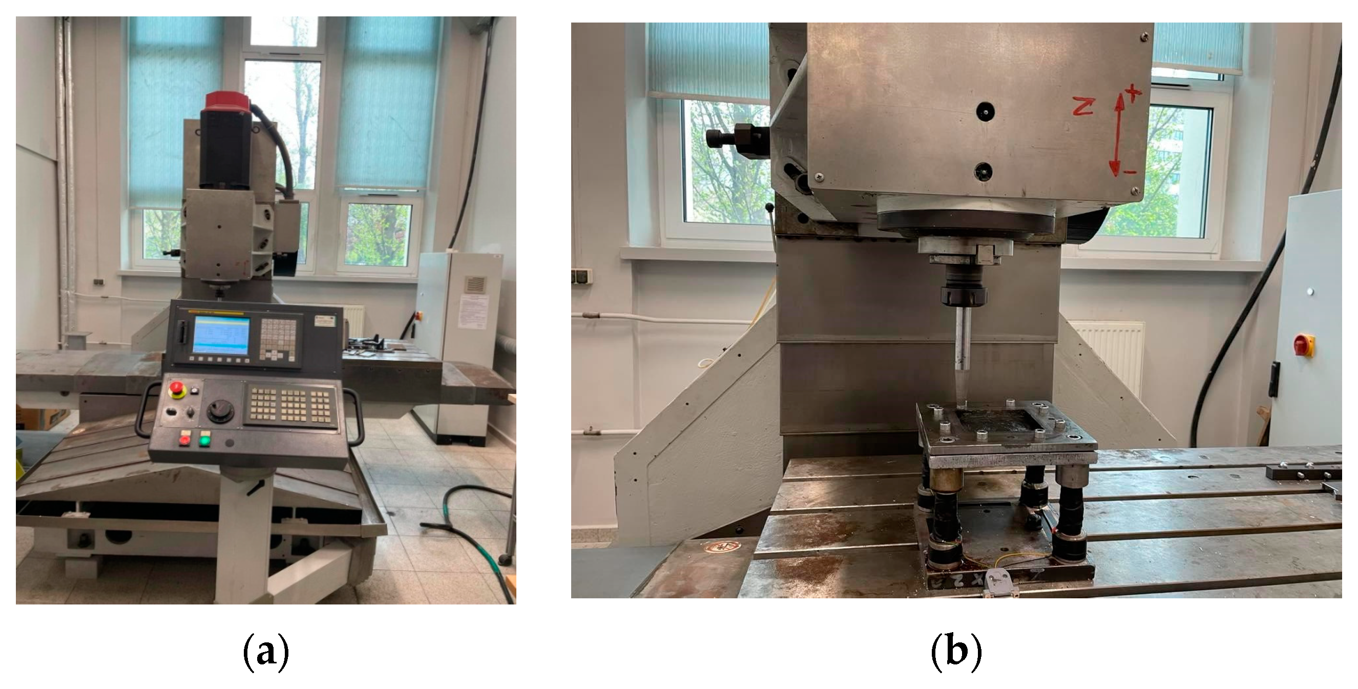
2.2. Incremental Sheet-Forming Methodology

The tests of incremental forming of sheets were carried out on a 3-axis milling machine (Figure 1a) with a mounted table for holding the workpiece and a spherically ended tool with a radius of 6 mm (Figure 1b). The forming tool was made of NC6 (1.2063) tool steel, heat-treated by holding at 830 °C for 2 h, quenching in oil at 20 °C and tempering at 250 °C for 6 h, resulting in an average hardness of 58 HRC. The following forming parameters were used: a feed rate of 500 mm/min, a tool rotational speed of 1500 rpm and a vertical step size of 1 mm. Incremental sheet forming was carried out under conditions of graphite grease lubrication. Based on the forming tests, the limit-forming angles of a square pyramid drawpiece were determined for materials subjected to heat treatment. The wall thickness distribution in the drawpieces was also determined based on the thickness measurement at specific points of the wall (Figure 2a) using a micrometre screw with a rounded anvil and spindle tips. For a given drawpiece, the measurement was performed on each of the pyramid walls. Surface roughness parameters were also measured in the direction parallel and perpendicular to the drawpiece axis, both for the outer and inner surfaces of the walls. A Hommel T1000 profilometer was used to analyse surface roughness. The dimensions of the pyramidal drawpiece base were the same, regardless of the applied drawpiece wall angle, and were equal to 84 × 84 mm. The drawpiece height depended on its wall angle and ranged from about 67 mm (for wall angle of 60°) to 103 mm (for wall angle of 69°). During the forming tests, the temperature of sheet during SPIF process was determined using a FLIR T640 thermal imaging camera. In order to determine the emissivity value, a layer of graphite grease was applied to the upper surface of the tested aluminium alloy sheet with the similar thickness as during the SPIF tests. Then, the surface temperature of the sheet was determined at different values of the emissivity coefficient, at different sample heating temperatures (RT, 40, 71 °C). The samples were heated in a furnace, and their temperature was determined using a K-type thermocouple. The comparison of the results allowed the determination of the emissivity coefficient of the 6082 alloy sheet.
After incremental forming, the selected samples were subjected to additional heat treatment under the conditions given in Table 4. The samples were also subjected to microstructural examination. Selected mechanical properties were also determined.
The mechanical properties of the drawpiece material after forming were determined on an Instron TM-SM testing machine with a strain rate of 3·10−3 s−1. Due to the small surface area of the drawpiece walls, the measuring base of the tensile samples was 10 mm long and 1 mm wide. To determine the elongation at rapture, two parallel lines perpendicular to the sample axis were drawn on the surface of the samples, and the distance between them was measured using a caliper with a measurement uncertainty of ±0.02 mm. The tensile samples were cut parallel and transversely to the axis of the drawpiece walls (Figure 2b). The Vickers hardness of the drawpiece material was measured using a Tukon 2500 hardness tester at a load of 9.81 N. The microstructure of the drawpiece material was also analysed using a HITACHI S-3400N scanning electron microscope.

3. Results and Discussion

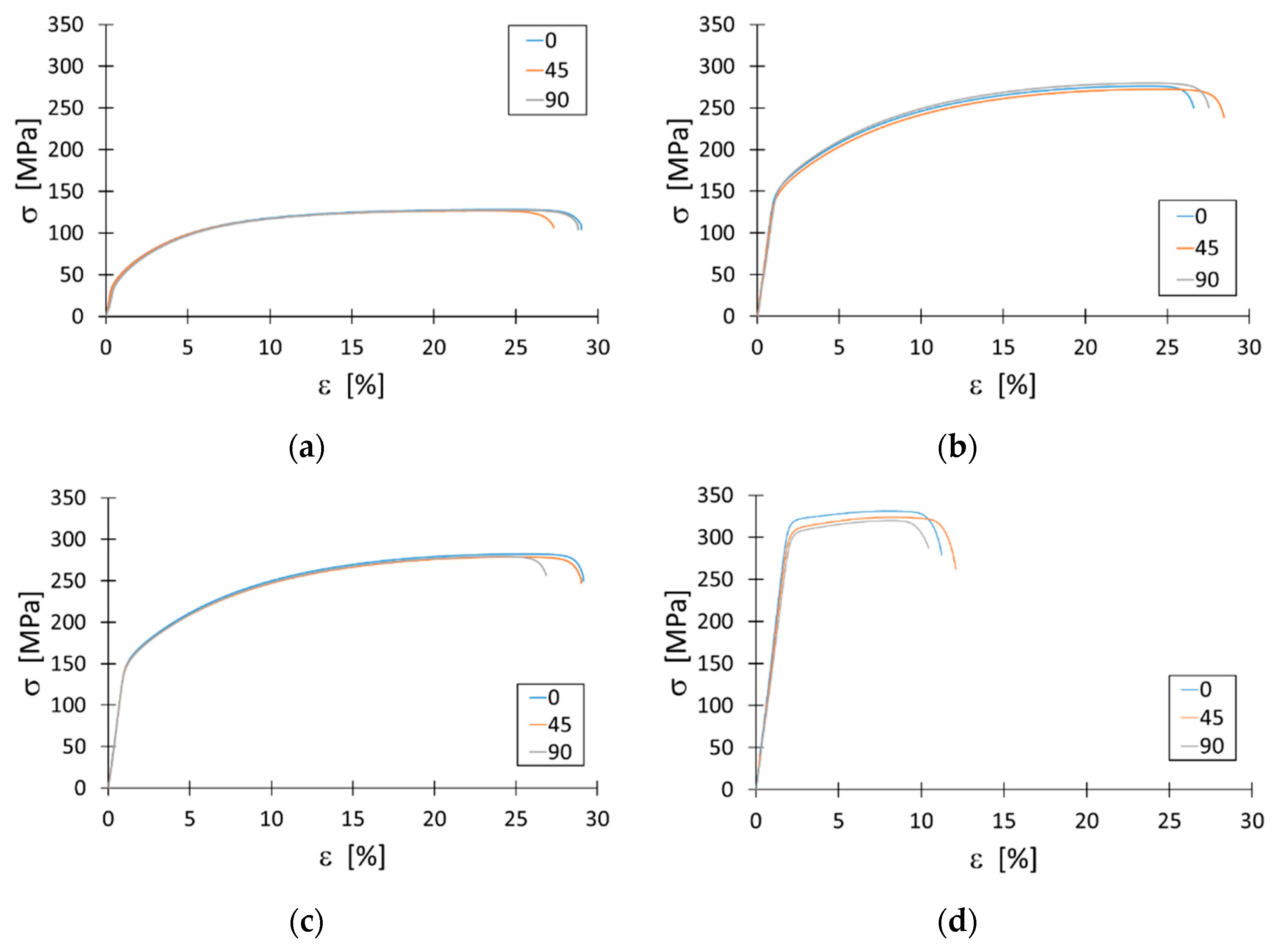
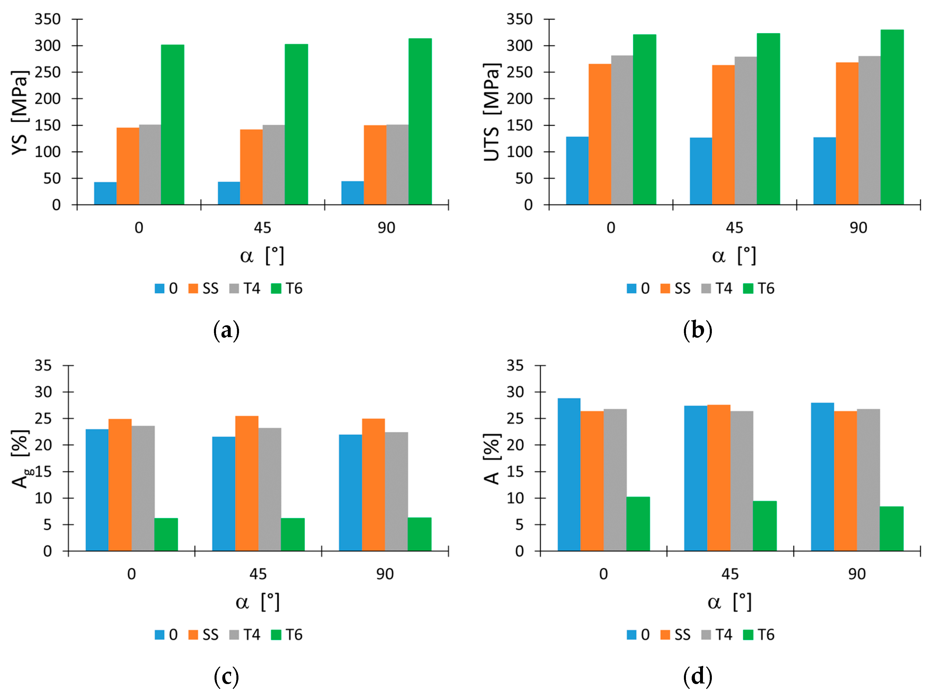
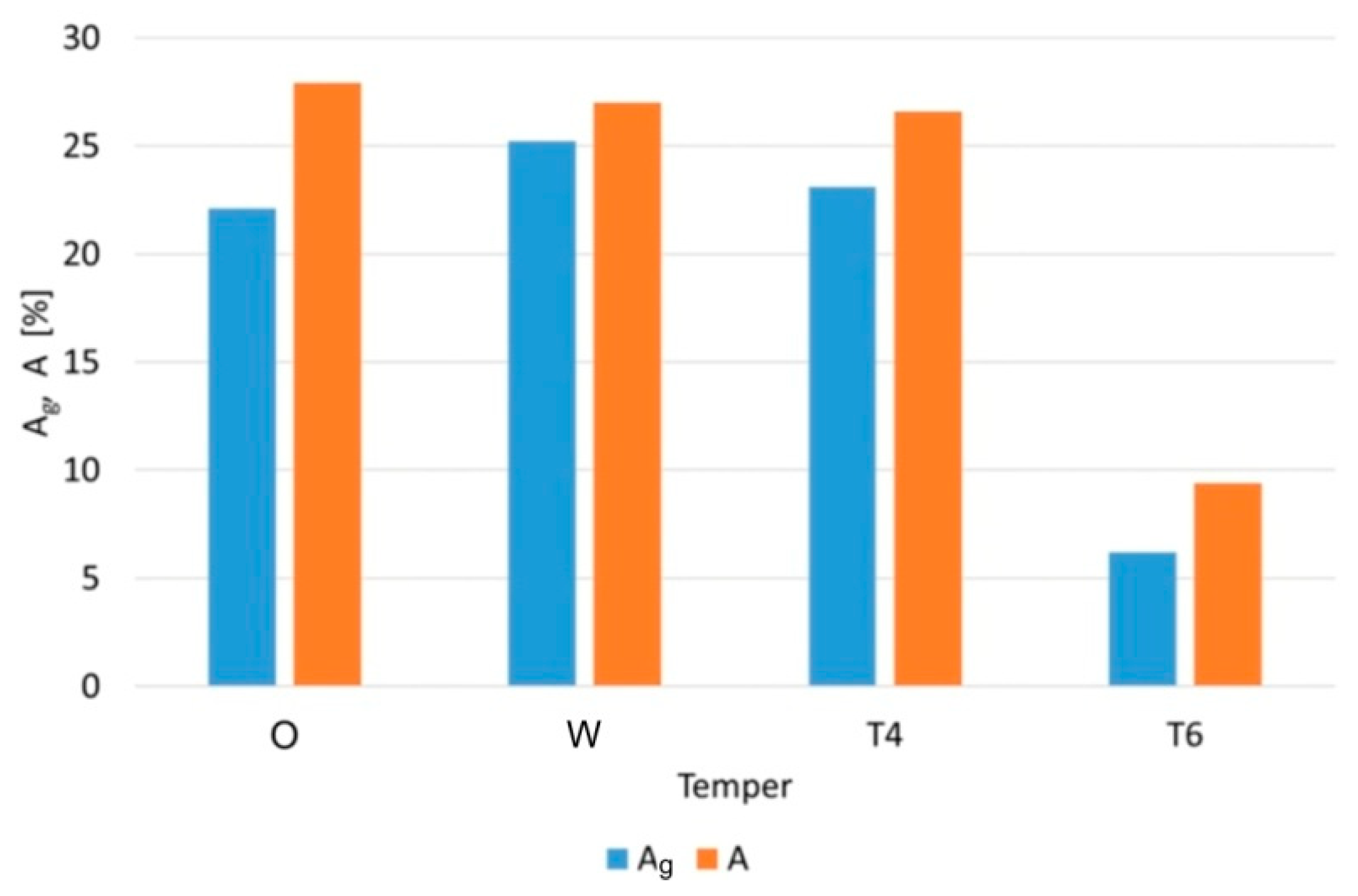
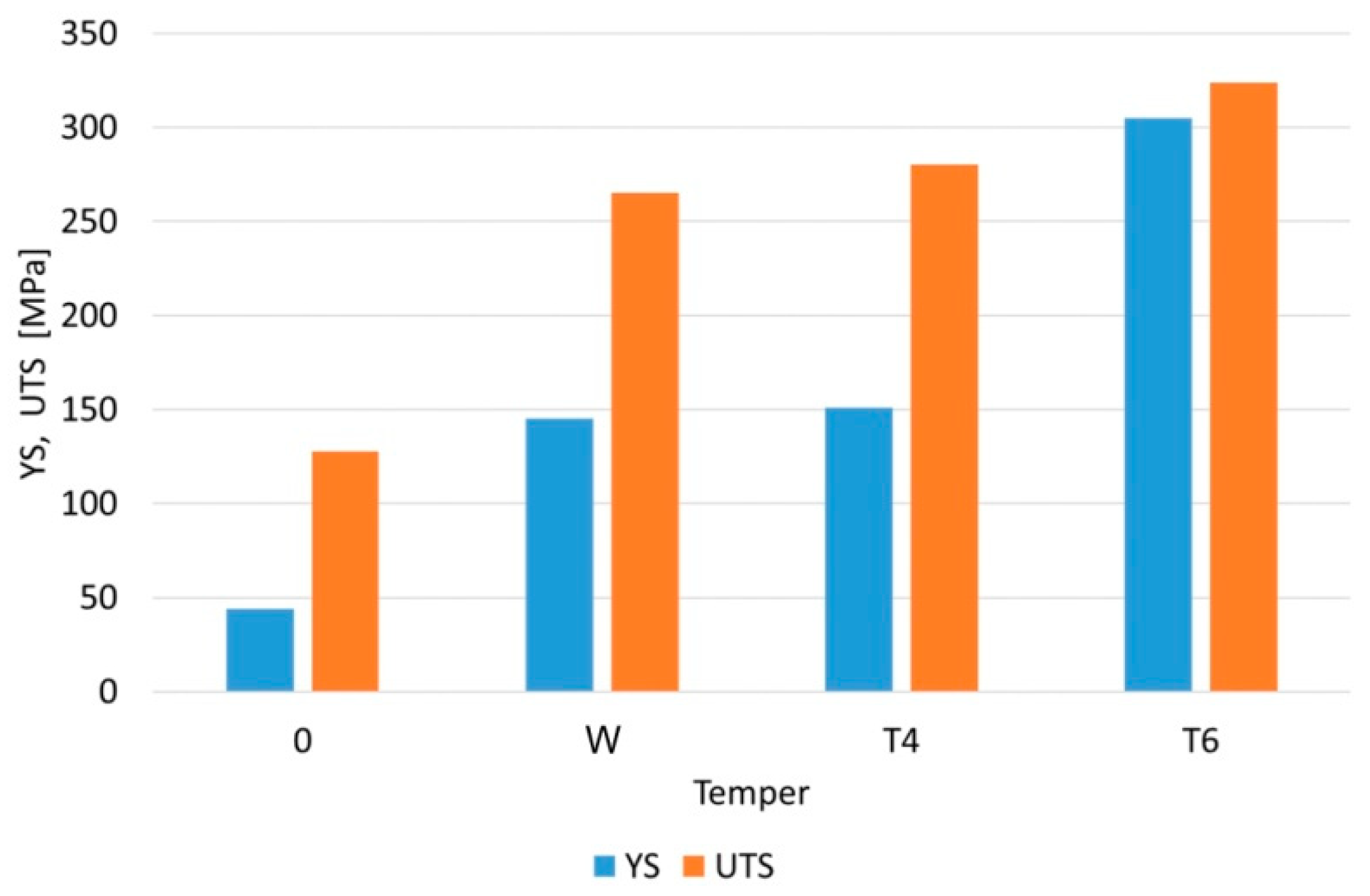
3.1. Mechanical Properties of Sheet Metals

Figure 3a–d show tensile stress-strain curves depending on the material hardening state and orientation relative to the rolling direction. Table 5 presents the values of the mechanical properties of the test materials. The obtained values of mechanical parameters for each sample orientation and tempering designation were similar. Solutionising and artificial ageing (T6) increase strength properties while reducing plastic properties compared to the annealed state. A slight anisotropy of mechanical properties was observed (Figure 4a–d). In the case of elongation, EN AW-6082-O, EN AW-6082-W and EN AW-6082-T4 sheets exhibit similar values of elongation range from 26 to 28% (Figure 5). Only in the case of the artificially aged material (T6) were significantly lower elongation values (A = 9.4%) observed. Artificial ageing also contributed to significantly higher strength properties of the material (Figure 6). At the same time, a small plasticity reserve could be observed, which is the difference between the UTS and the YS. A small value of this parameter means a low tendency of the material for deep drawing. For the solution-heat-treated (W) and naturally aged (T4) materials, similar values of mechanical properties were found. These parameters had a significant influence on the process of incremental sheet forming.

3.2. Sheet Hardness

Table 6 shows the Vickers HV1 hardness values of EN AW-6082 alloy sheets in various temper states. As in the case of ultimate tensile strength, the highest hardness was observed for the sheet in the T6 temper state. For the solutionised material (W) and the naturally aged (T4) material, similar hardness values were found, which influenced the ISF process. In the T4 and T6 tempers, the hardness of the material was 84 and 118% higher compared to the O temper, respectively. When comparing the W and T4 tempers, the difference was small and amounted to 4%. The hardness of aluminium alloys is determined by the concentration of hardening phases formed in the aging process. The hardness of the alloy results from the tendency of the precipitates to retain mobile dislocations and is determined by their size and distribution. During deformation, small and soft precipitates are sheared as a result of dislocation movement. The strength of the precipitates is directly proportional to the size of the precipitates. With the growth of the precipitates, their shearing, according to the Mott-Nabarro mechanism, requires increasingly greater stress. At a certain strain of the material during slip, individual segments of the dislocation lines begin to move between the precipitates, leaving closed Orowan loops around them.

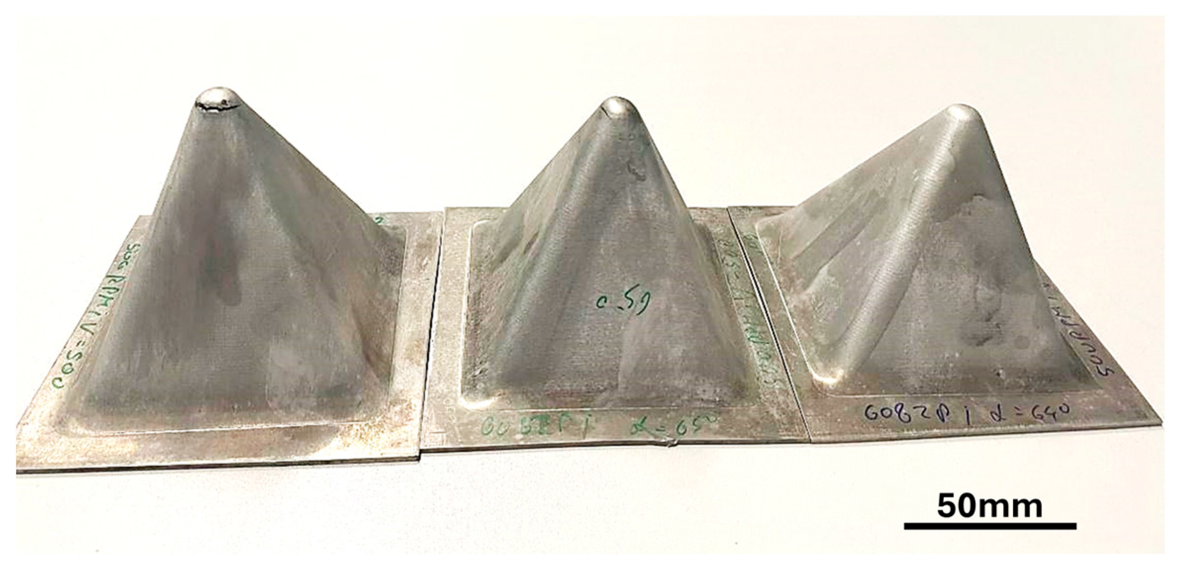
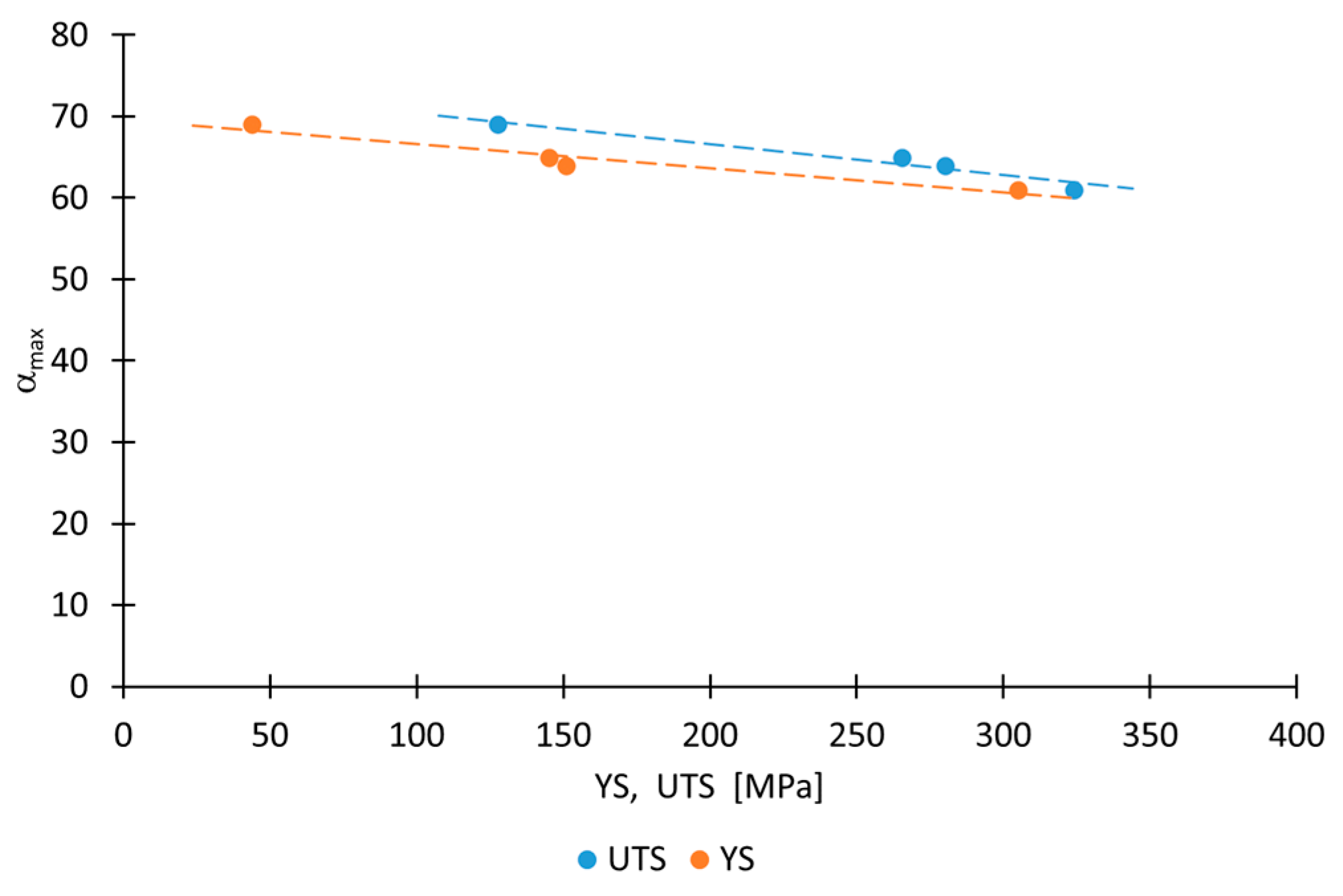
3.3. The Limit-Forming Angle

Figure 7 shows a photograph of square pyramids after ISF. Table 7 shows the values of the limit-forming angle as a function of the material hardening state. The highest value of the limit-forming angle αmax was found for the annealed sheet (αmax = 69°), and the lowest for the artificially aged material (αmax = 61°). These values correspond to the strength properties of the workpiece materials (Figure 8). Increasing both the YS and the UTS reduces the value of the limit-forming angle αmax. The increase in the strength of the material as a result of heat treatment causes a decrease in its tendency to plastic deformation. Since plastic deformation is associated with the movement of dislocations, the occurrence of the work hardening phenomenon means that the resistance to the movement of dislocations increases in the deformed sheet metal. This resistance increases with the increase in the density of dislocations caused by plastic deformation. The forming angle is one of the basic parameters in SPIF for assessing the formability of the material. Based on the obtained results, it can be stated that the material in the ‘O’ state is the most susceptible to deformation.

3.4. Temperature During Forming

During the incremental sheet forming of square pyramids, a thermal imaging camera was used to determine temperature distribution (Figure 9). For this purpose, the emissivity coefficient values were first determined by simultaneously determining the surface temperature of the sheet metal using a thermal imaging camera (at different emissivity values set) and a K-type thermocouple (Figure 10). The emissivity coefficient determined in this way was used to determine the surface temperature of the material during forming using the SPIF method. Its average value was 0.95.
It was found that during the ISF process, the maximum temperature at the point of contact between the end of tool and the sheet metal increased with the forming time, rising from room temperature to about 90 °C for the annealed sheet and to about 130 °C for the naturally aged sheet.

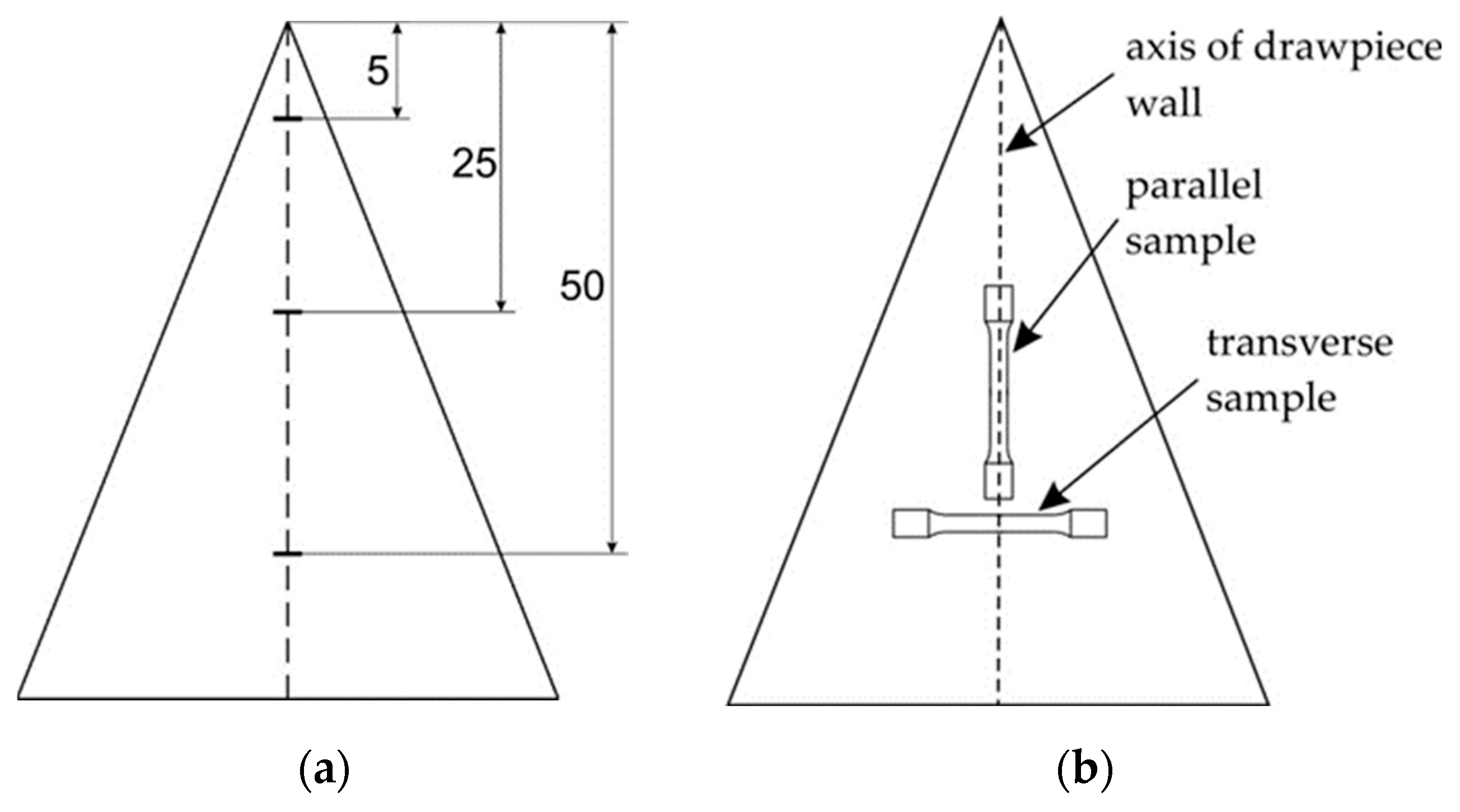
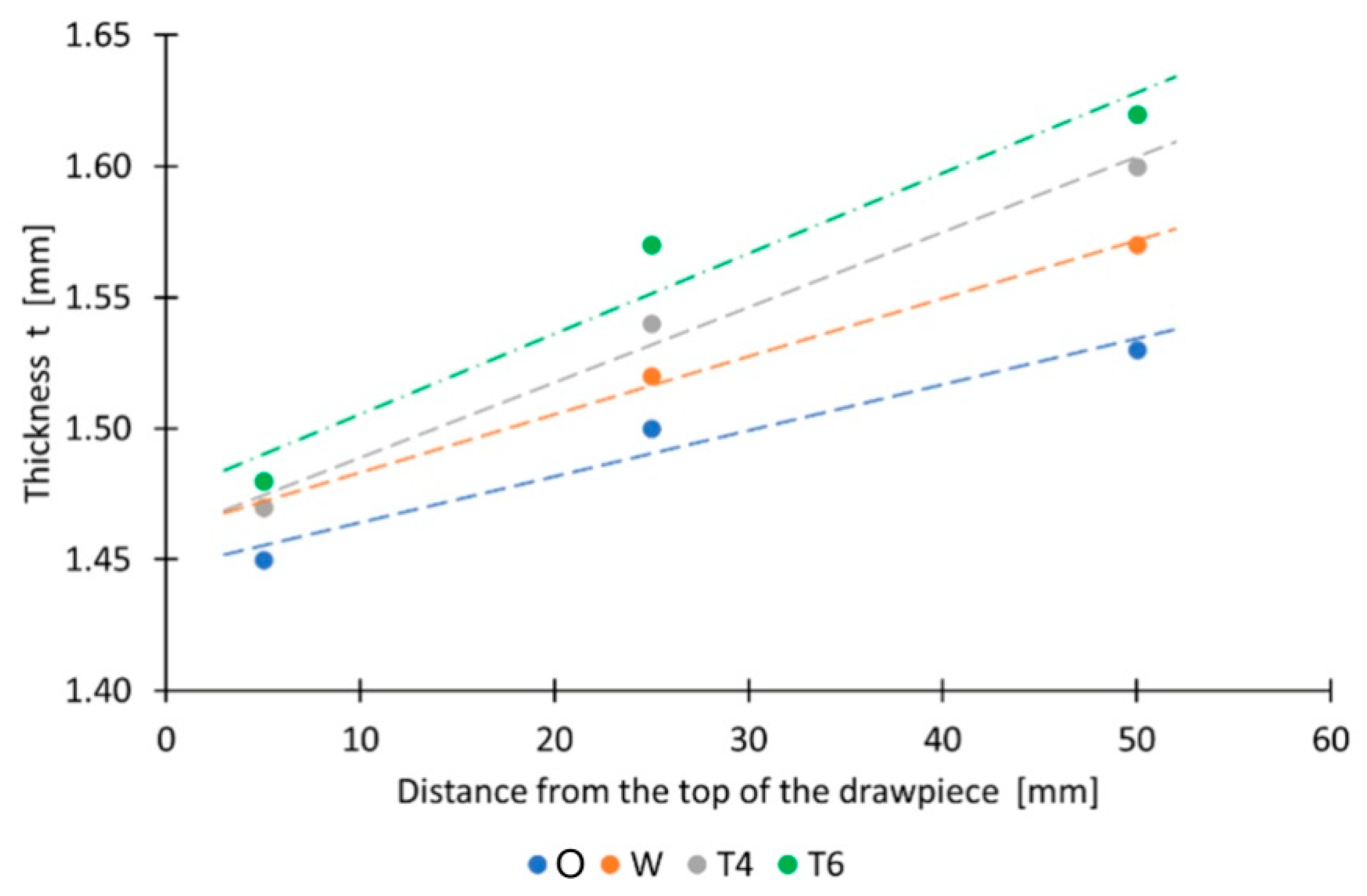
3.5. Drawpiece Wall Thickness
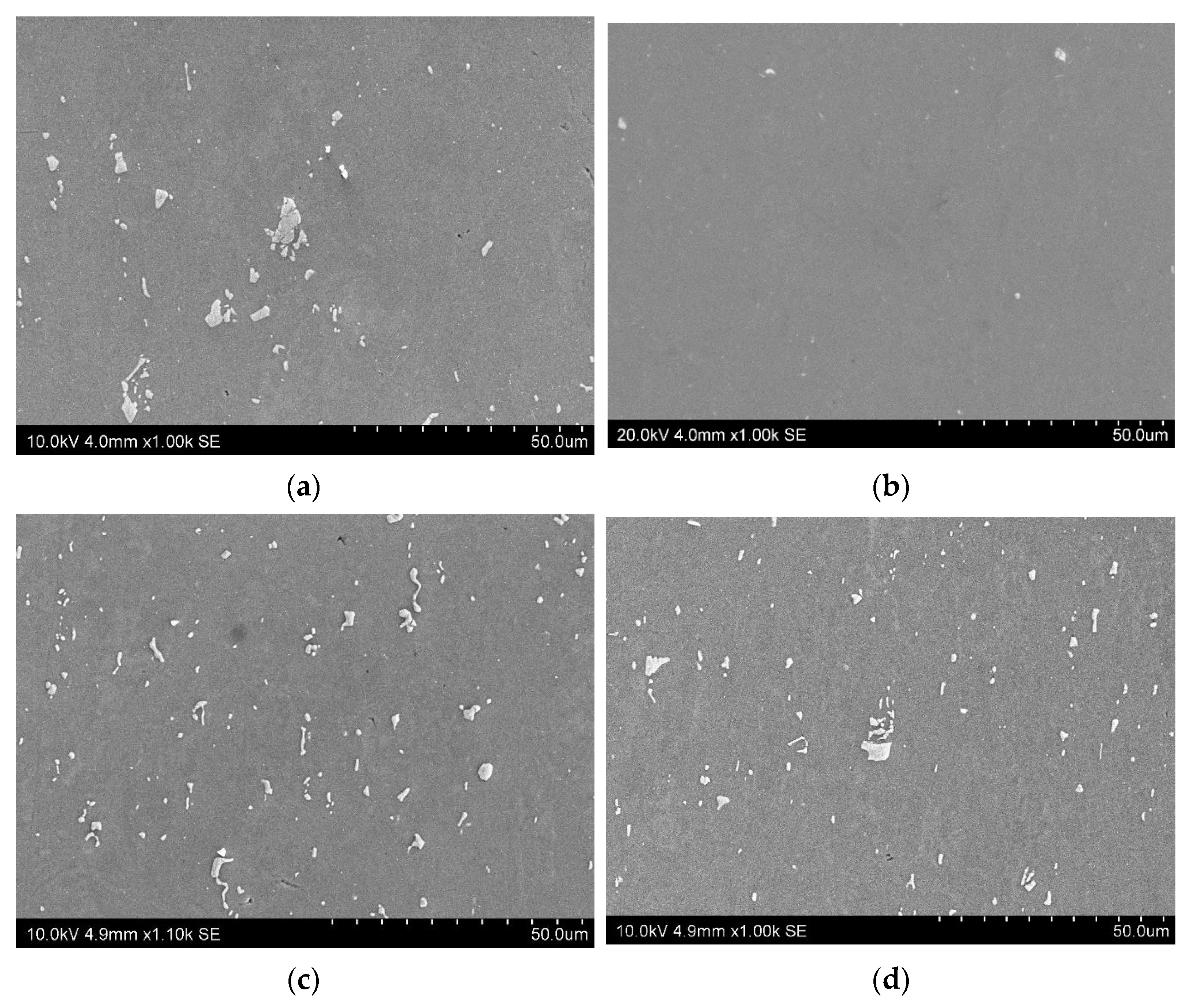
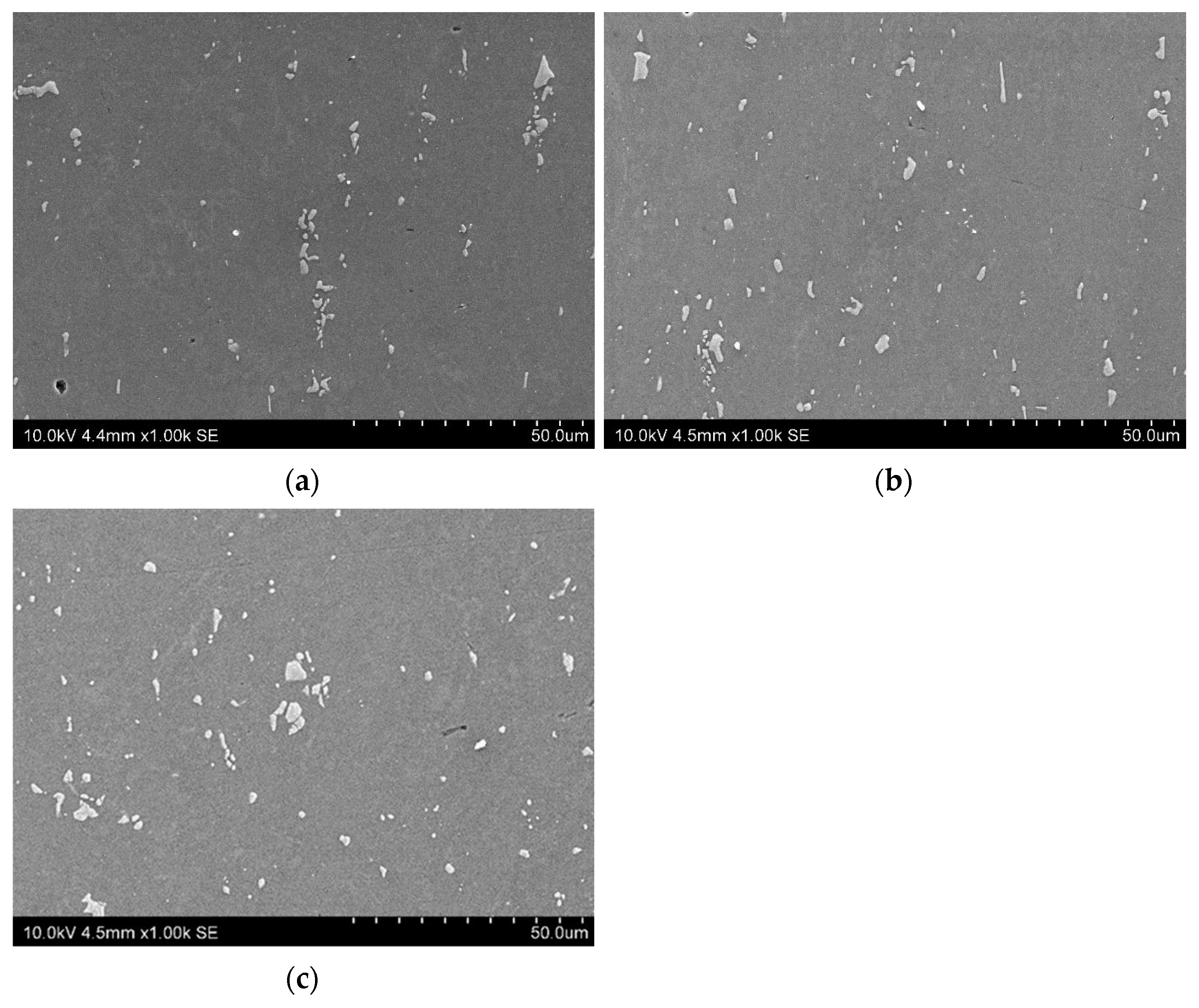
Table 8 presents the vales of the drawpiece wall thickness depending on the temper state of sheet metal. In all cases, a variable wall thickness was found along the drawpiece height (Figure 11). For the tested materials, the sine law, commonly used in incremental sheet forming (defined according to Equation (1)), was not fulfilled. The measured wall thicknesses were significantly higher (Table 8).
t 1 = t 0 s i n π 2 α m a x
where t0 is the sheet thickness and t1 is the wall thickness of the drawpiece.
The character of the wall thickness changes can be mainly related to the circumferential strains of the material and the strains in the axial direction, changing along the height of the drawpiece. The higher the drawpiece height, the greater the wall thinning. The smallest wall thickness was observed for the ‘O’ temper. In this annealed state, the sheet is most susceptible to plastic deformation. The ‘T6’ temper state provides the highest strength and the smallest elongation, which is drastically lower compared to other states (Figure 5). Nevertheless, the obtained wall thicknesses were the largest among all the materials tested.
In fact, the sine law can only provide a rough approximation of the wall thickness. According to Sakuda et al. [44], the largest deviations occur at the base of the drawpiece and in the tip region. Significant discrepancies between the thickness predicted by the sine law and the experimental values were also confirmed by Ambrogio et al. [45] when forming a pyramidal shape with a square basis.

3.6. Microstructure

Figure 12 and Figure 13 show examples of the microstructure of the sheet metal and drawpieces as a function of the heat treatment. In all cases, the presence of precipitates was observed. In the case of the material subjected to solutionizing only, their amount was the smallest. No significant changes in the microstructure were observed as a result of the incremental forming process. Additional heat treatment after incremental forming contributed to an increase in the amount of precipitates, mainly in the case of the material deformed in the solution-heat-treated state (Figure 12b and Figure 13b,c).
The solution heat treatment was carried out to dissolve the phases containing Cu and Mg formed during the solidification process, homogenize the alloying elements and spheroidize the eutectic silicon particles. It consists in heating the alloy to the maximum dissolution temperature of the second alloying element above the solvus line and heating at this temperature for a period sufficient to allow the alloying elements not dissolved in aluminium to pass into the solid solution. With the increase in the supersaturation temperature, the solubility of the elements in the matrix increases, which increases the hardness of the alloy [46]. During ageing following solution heat treatment, coherent phases associated with the matrix are obtained, and the excess components present in the solution are precipitated. This leads to alloy strengthening. In Al-Si-Mg alloys, ageing starts with the formation of spherical Guinier–Preston zones consisting of enriched Mg and Si atoms. These zones expand and elongate into a coherent β″ phase having a needle-like shape. The peak yield strength of the alloy increases with the increase in Mg concentration in the alloy, with the increase in the yield strength value being linear [42].

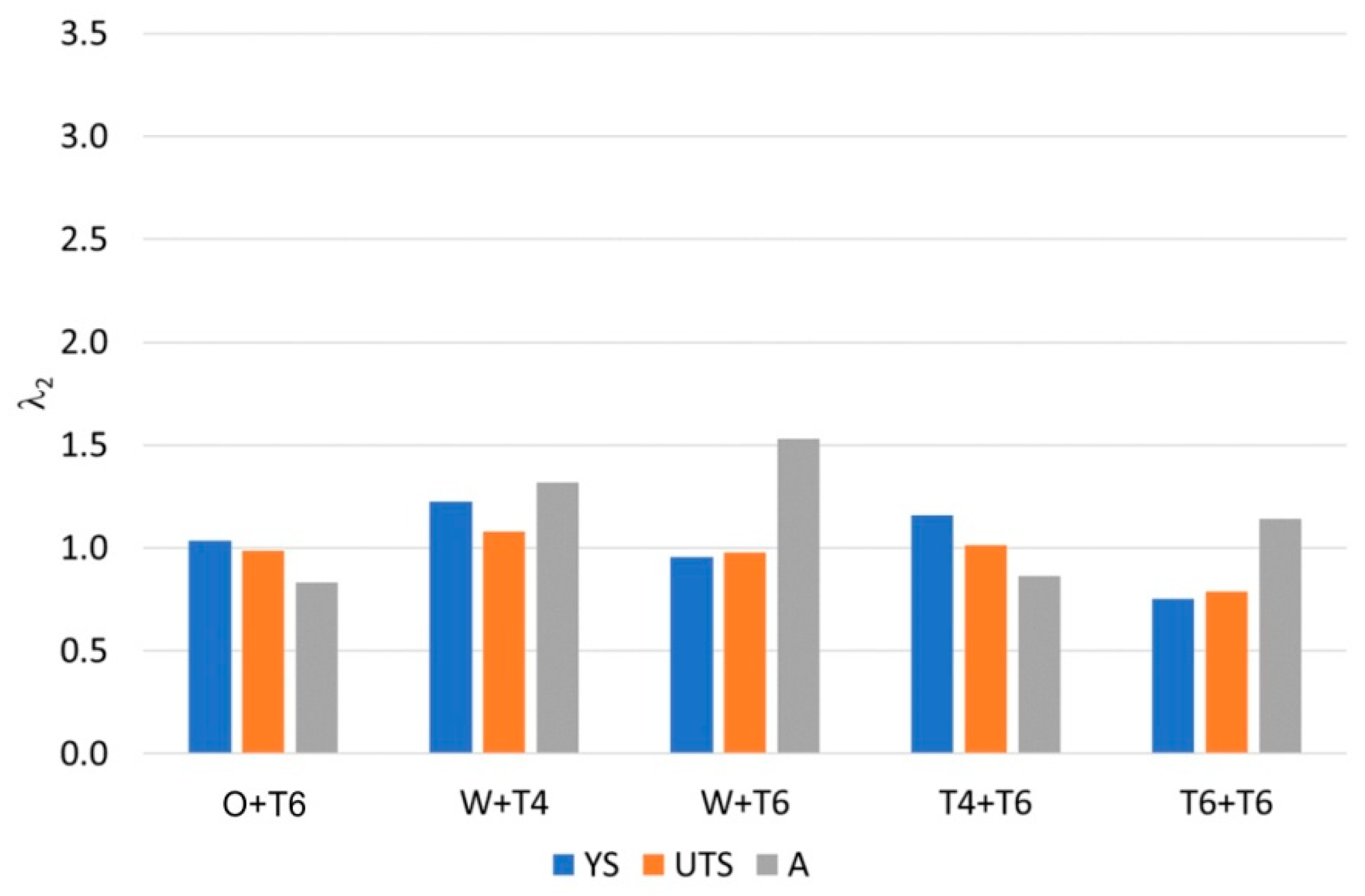
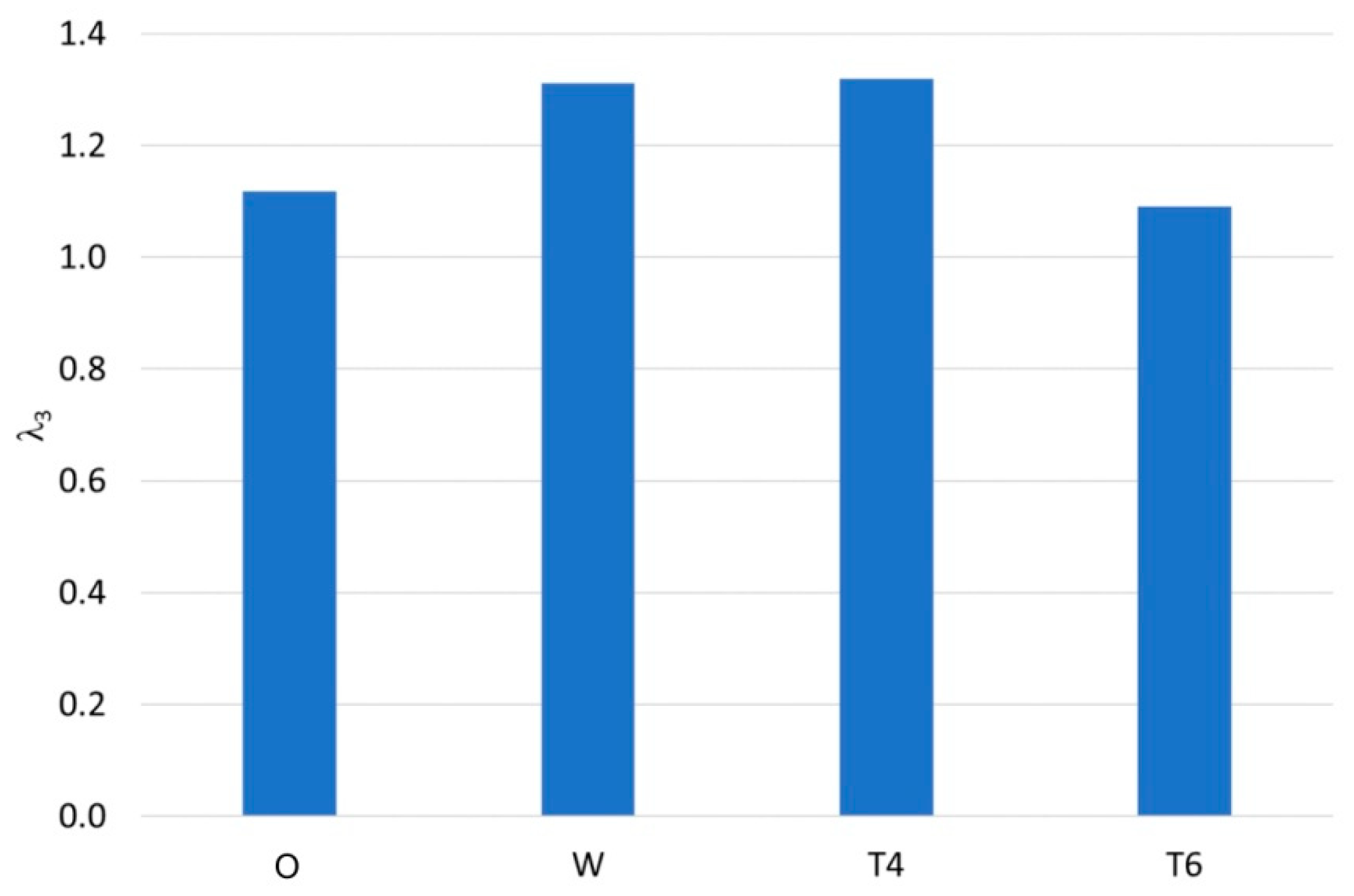
3.7. Mechanical Properties of Drawpieces

Table 9 presents the mechanical properties of the drawpieces measured in the directions parallel and transverse to the drawpiece axis, depending on the temper state of the workpiece material and additional heat treatment (HT) after forming. The values of yield stress, ultimate tensile strength and elongation were higher for the parallel direction compared to the transverse direction.
Figure 14 shows the change in the value of mechanical properties (λ1) of the drawpieces in relation to the values determined for the sheet metal. Figure 15 shows the effect of additional heat treatment on the properties of the drawpieces (λ2). The coefficients λ1 and λ2 were determined according to the following relationships:
λ 1 = Y S ; U T S ; A d r a w p i e c e Y S ; U T S ; A s h e e t
λ 2 = Y S ; U T S ; A d r a w p i e c e + H T Y S ; U T S ; A d r a w p i e c e
It was found that as a result of incremental sheet forming, the strength of the material increased, especially in the case of annealed sheet. The lowest increase in the λ1-value for the YS and UTS was noted for artificially aged sheet metal (Figure 14). The opposite situation was found for the case of elongation. The smallest decrease in the λ1-value for elongation A was determined for the material in the T6 tempering state. This effect was mainly related to the work-hardening phenomenon as a result of incremental forming. In the case of the drawpiece made of annealed sheet, a larger limit-forming angle was obtained, and consequently, a larger degree of deformation, which in turn contributed to a greater work-hardening of the material in relation to the sheet in the as-received state.
The work-hardening phenomenon is associated with the increase in flow stresses caused by permanent (plastic) deformation. There are two mechanisms of plastic deformation in metallic materials in cold working: twinning and slip. Twinning consists in twinning one part of the crystal relative to the neighbouring ones by a certain angle. Slip consists in shifting parts of the crystals relative to each other along specific lattice planes under the influence of external forces. Slip occurs in slip planes with the densest arrangement of atoms. Slip is the process of dislocation movement. During deformation, the number of active slip planes and free dislocations, which are generated during deformation, increases. The stresses causing twinning are greater than the stresses necessary for dislocation movement.
Additional ageing after incremental forming had various effects on the properties of the drawpieces (Figure 15). In the case of the drawpieces made from annealed sheet, additional heat treatment contributed to slight changes in strength properties (increase in YS and decrease in UTS), with a simultaneous clear decrease in elongation A. On the other hand, additional natural ageing performed on the drawpiece made of solutionised sheet (W + T4) resulted in an increase in the material properties. Artificial ageing of the solutionised material (W + T6) and in the T6 condition only resulted in an increase in elongation A of the material, with a simultaneous decrease in the YS and UTS. This can probably be associated with the ageing of the material. In the case of T4 + T6 samples, an increase in strength and a decrease in elongation were observed. This means that additional artificial ageing occurred in the material.

3.8. Hardness of Drawpieces

Table 10 presents the hardness of the material after incremental forming and after additional heat treatment. Similarly to the strength properties, incremental forming contributed to an increase in hardness, which was associated with the work-hardening of the material (Figure 16), despite the temperature increase [29]. On the other hand, the application of additional heat treatment caused an increase in hardness in the case of the drawpieces made of solutionised and naturally aged material after forming (W + T4) and drawpieces made of EN AW-6082-T4 sheet metal and artificially aged sheet metal (Figure 17). In the remaining cases, there was a decrease in hardness, while additional ageing for the drawpieces made of EN AW-6082-T6 alloy caused an increase in thermal diffusivity [12,13,14,15] and overageing of the material.

3.9. Surface Roughness

Table 11 presents the results of the measurement of the basic surface roughness parameters of the inner and outer walls of the drawpiece, depending on the sheet hardening state. The average value of the Ra parameter for the EN AW-6082 alloy sheet before forming was 0.68 μm, and the maximum height of profile was Rz 3.62 μm. An increase in the values of the surface roughness parameters of the drawpieces was observed when compared to the undeformed sheet metal. In the case of the outer surface, lower values of the Ra and Rz parameters were obtained compared to the inner surface. Although the outer surface of the drawpiece is freely formed, due to the large deformations of the sheet metal in the circumferential and radial directions, a roughening effect is created. This effect is known as orange peel and consists in changing the orientation of neighbouring grains under the influence of the plastic deformations. The amount of free surface roughening is affected by the size of grains and the amount of plastic deformation [47].
Additionally, the surface roughness parameters measured in the direction parallel to the axis of the drawpiece wall was higher in all cases, which was related to the cyclic effect of the tool moving along a trajectory with a vertical step size of 1 mm. This resulted in the formation of the linear cyclic grooves on the inner surface of the drawpieces (Figure 18). The use of a smaller step size could contribute to the reduction in the surface roughness parameters, especially in the direction parallel to the axis of the drawpiece wall.
During the motion of the tool over the sheet, friction plays a vital role in ensuring the proper surface roughness of the drawpieces. In SPIF, friction between tool and workpiece is very high, and thus it leads to galling, especially in the case of aluminium alloys, which are susceptible to abrasion and galling. The deterioration of the internal surface quality in SPIF is a well-known issue [48]. Through appropriate lubrication and the use of tools with a rotating tip, the influence of the tool on the deterioration of the surface finish can be minimized. The intensity of the tool impact also depends on the SPIF process parameters such as feed rate, tool diameter, step depth and wall angle [49]. The quality of the incrementally formed components is particularly limited by the step size. Reducing the step size improves the surface quality; however, reducing this factor makes the process time very long [50]. Long processing time is one of the disadvantages of the SPIF process, but, at the same time, this process allows for much larger limit deformations compared to conventional sheet metal forming techniques [51].

4. Conclusions

The article presents the results of the analysis of the effect of heat treatment of EN AW-6082 aluminium alloy sheet on the quality of drawpieces and formability of the material during the incremental sheet-forming process. The influence of additional heat treatment on the microstructure and mechanical properties of the drawpieces was also analysed. Based on the results, the following conclusions can be drawn:
  • Incremental forming had no effect on the size and number of the observed precipitates in the material. However, additional heat treatment after forming contributed to the observation of additional precipitates in the test materials, especially in the case of drawpieces made from solutionised sheet metal and sheet metal that was aged after the ISF process.
  • The hardening state of the workpiece material had a significant effect on the formability of the material in the ISF process. It was found that with the increase in the strength of the material (from the O condition to the T6 tempering state), the value of the limit-forming angle of the drawpiece wall decreased from 69° (for annealed sheet) to 61° (for artificially aged material), which was also associated with a decrease in the plasticity of the material.
  • As a result of incremental forming, the strength properties and hardness of the ISFed pyramids increased, despite the temperature increase at the contact area between the forming tool and the sheet metal to 130 °C. This was due to the dominant influence of work hardening on the material properties after forming. The greatest increase was observed for the drawpiece made of annealed sheet metal. In the case of material in the T6 condition, the lowest values of the limit-forming angle were obtained and, consequently, the lowest increase in material strength.
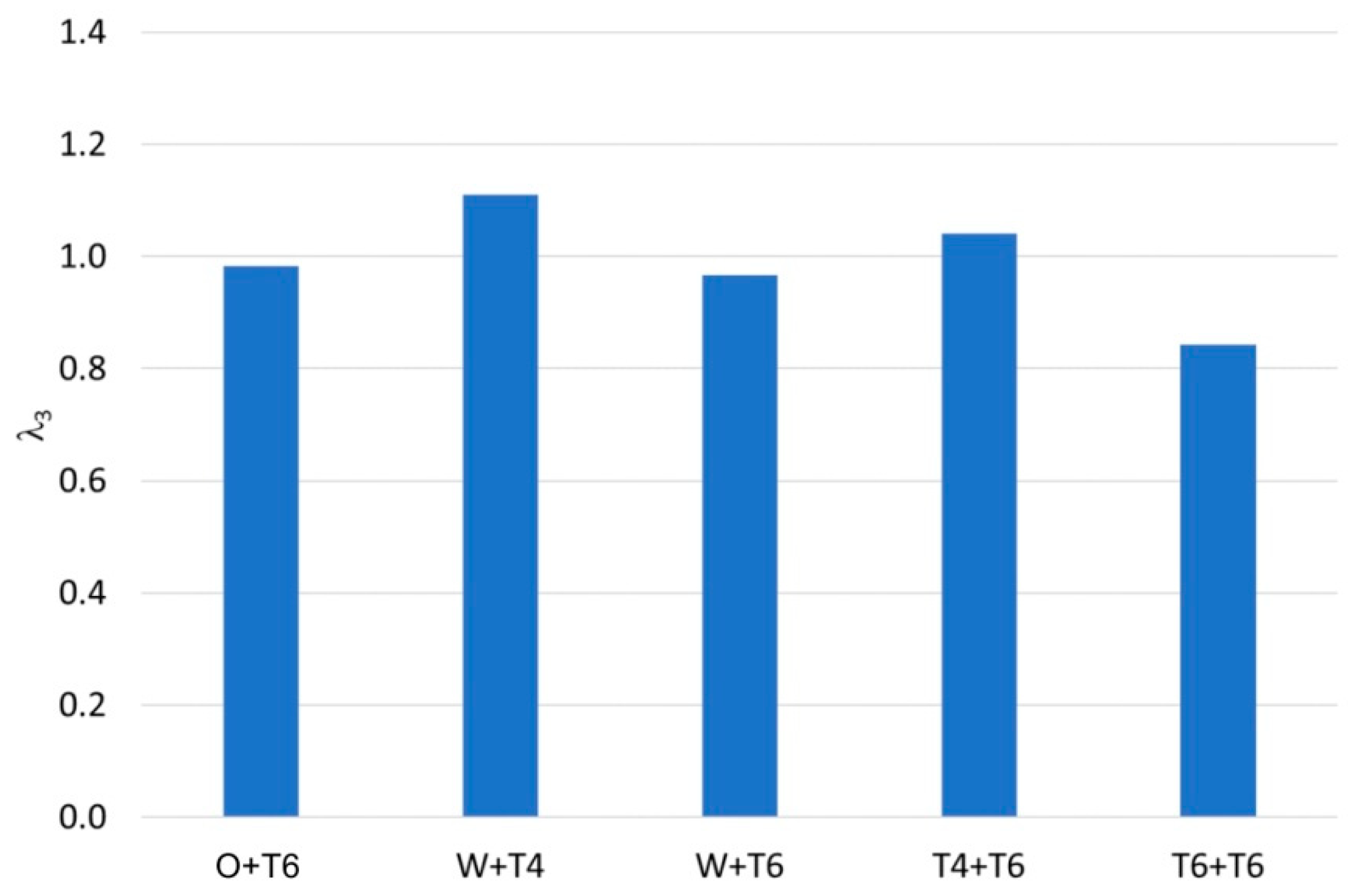
  • Additional heat treatment after forming contributed to the increase in strength and hardness properties only in the case of drawpieces made of solutionised workpiece metal (and naturally aged after forming) and naturally aged workpiece material (and artificially aged after forming). In these materials, further precipitation hardening of the EN AW-6082 aluminium alloy occurred. In the remaining cases, especially for the T6 + T6 material, there was a decrease in strength, which may be related to the ageing of the material as a result of excesively long heating at 170 °C (for 6 h).
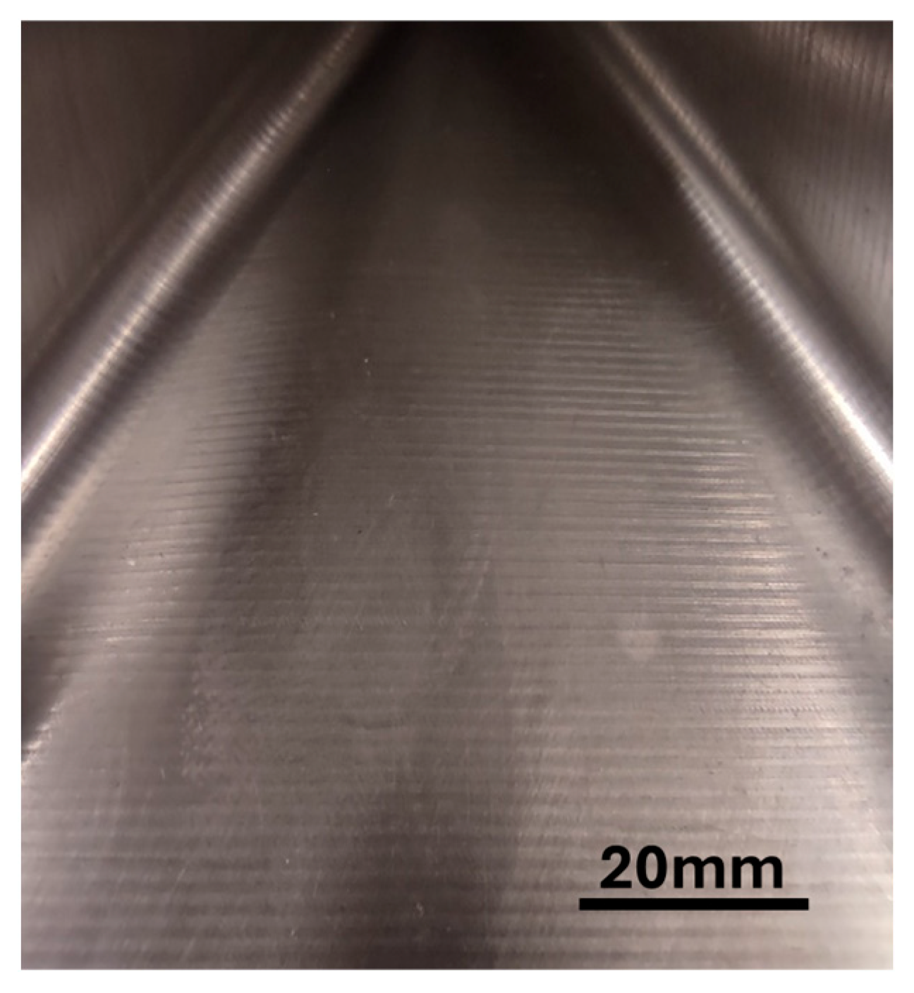
  • The surface roughness of the walls of the drawpieces was higher than that of the sheet metal in the as-received state, especially when measured in the direction parallel to the drawpiece wall axis. This was related to the ISF process conditions, especially the vertical step size. The use of a lower vertical stem size value could contribute to lower values of the Ra and Rz parameters.
A hardened state of material has a significant impact on the degree of deformation in the ISF process. The forming of annealed sheets (O condition) contributes to obtaining drawpieces under a higher forming angle, but their strength properties are lower than those of other hardened states of material, despite work-hardening and additional heat treatment. On the other hand, sheets made from EN AW-6082-T6 aluminium alloy allow for obtaining drawpieces of high strength, but with a lower height than in the other cases. The most optimal case seems to be the manufacturing of drawpieces by incremental forming processes, from sheets that were subjected to solutionizing immediately before ISF and then additionally naturally aged after forming. A sufficiently high strength of the drawpieces material with relatively good formability can also be ensured by the strategy of forming EN AW-6082-T4 sheets, which are then subjected to artificial ageing.

Author Contributions

Conceptualization, Ł.K. and K.Ż.; methodology, Ł.K. and M.B.; validation, K.Ż. and T.T.; formal analysis, Ł.K., M.W. and T.T.; investigation, Ł.K. and M.W.; data curation, M.W., R.S. and M.B.; writing—original draft preparation, Ł.K. and M.W.; writing—review and editing, T.T. and K.Ż.; visualization, M.W. and R.S.; supervision, K.Ż. and T.T.; project administration, Ł.K. and R.S. All authors have read and agreed to the published version of the manuscript.

Funding

This research received no external funding.

Institutional Review Board Statement

Not applicable.

Informed Consent Statement

Not applicable.

Data Availability Statement

Data are contained within the article.

Conflicts of Interest

Author Mateusz Wąsikowski was employed by the company Assa Abloy Opening Solutions Poland S.A. The remaining authors declare that the research was conducted in the absence of any commercial or financial relationships that could be construed as a potential conflict of interest.

References

  1. Trzepieciński, T.; Najm, S.M. Current Trends in Metallic Materials for Body Panels and Structural Members Used in the Automotive Industry. Materials 2024, 17, 590. [Google Scholar] [CrossRef]
  2. EN 1706:2020; Aluminum and Aluminum Alloys—Castings—Chemical Composition and Mechanical Properties. European Committee of Standardization: Brussels, Belgium, 2020.
  3. PN-EN 573-3:2020+A1:2022-11; Aluminium and Aluminium Alloys—Chemical Composition and Form of Wrought Products—Part 3: Chemical Composition and Form of Products. PKN: Warsaw, Poland, 2022.
  4. Langille, M.R.; Diak, B.J.; De Geuser, F.; Deschamps, A.; Guiglionda, G. Asymmetry of strain rate sensitivity between up- and down-changes in 6000 series aluminium alloys of varying Si content. Mater. Sci. Eng. A 2020, 788, 139517. [Google Scholar] [CrossRef]
  5. Xu, X.; Liu, Z.; Zhang, B.; Chen, H.; Zhang, J.; Wang, T.; Zhang, K.; Zhang, J.; Huang, P. Effect of Mn content on microstructure and properties of 6000 series aluminum alloy. Appl. Phys. A 2019, 125, 490. [Google Scholar] [CrossRef]
  6. Ismail, A.; Mohamed, M.S. Review on sheet metal forming process of aluminium alloys. In Proceedings of the 17th International AMME Conference, Cairo, Egypt, 19–21 April 2016; pp. 129–141. [Google Scholar]
  7. Kleiner, M.; Geiger, M.; Klaus, A. Manufacturing of lightweight components by metal forming. CIRP Ann. 2003, 52, 521–542. [Google Scholar] [CrossRef]
  8. Guzmán-Flores, I.; Granda-Gutiérrez, E.E.; Cruz-González, C.E.; Hernández-García, H.M.; Díaz-Guillén, J.C.; Flores-González, L.; Praga-Alejo, R.J.; Martínez-Delgado, D.I. Enhancing the mechanical properties of a 6061 aluminum alloy by heat treatment from the perspective of Taguchi design-of-experiments. Appl. Sci. 2024, 14, 5407. [Google Scholar] [CrossRef]
  9. Van Huis, M.A.; Chen, J.H.; Sluiter, M.H.F.; Zandbergen, H.W. Phase stability and structural features of matrix-embedded hardening precipitates in Al–Mg–Si alloys in the early stages of evolution. Acta Mater. 2007, 55, 2183–2199. [Google Scholar] [CrossRef]
  10. Ding, L.; Jia, Z.; Nie, J.-F.; Weng, Y.; Cao, L.; Chen, H.; Wu, X.; Liu, Q. The structural and compositional evolution of precipitates in Al-Mg-Si-Cu alloy. Acta Mater. 2018, 145, 437–450. [Google Scholar] [CrossRef]
  11. Naronikar, A.H.; Jamadagni, H.N.A.; Simha, A.; Saikiran, B. Optimizing the heat treatment parameters of Al-6061 required for better formability. Mater. Today Proc. 2018, 5, 24240–24247. [Google Scholar] [CrossRef]
  12. Nicolaides, L.; Mandelis, A.; Beingessner, C.J. Physical mechanisms of thermal-diffusivity depth-profile generation in a hardened lowalloy Mn, Si, Cr, Mo steel reconstructed by photothermal radiometry. J. Appl. Phys. 2001, 89, 7879–7884. [Google Scholar] [CrossRef]
  13. Fournier, D.; Roger, J.P.; Bellouati, A.; Boué, C.; Stamm, H.; Lakestani, F. Correlation between hardness and thermal diffusivity. Anal. Sci. 2001, 17, 158–160. [Google Scholar]
  14. Dell’Avvocato, G.; Palumbo, D.; Galietti, U. A non-destructive thermographic procedure for the evaluation of heat treatment in Usibor®1500 through the thermal diffusivity measurement. NDT E Int. 2023, 133, 102748. [Google Scholar] [CrossRef]
  15. Dell’Avvocato, G.; Bison, P.; Palmieri, M.E.; Ferrarini, G.; Palumbo, D.; Tricarico, L.; Galietti, U. Non-destructive estimation of mechanical properties in Usibor® 1500 via thermal diffusivity measurements: A thermographic procedure. NDT E Int. 2024, 143, 103034. [Google Scholar] [CrossRef]
  16. Formisano, A.; Boccarusso, L.; Durante, M. Optimization of single-point incremental forming of polymer sheets through FEM. Materials 2023, 16, 451. [Google Scholar] [CrossRef] [PubMed]
  17. Najm, S.M.; Paniti, I. Investigation and machine learning-based prediction of parametric effects of single point incremental forming on pillow effect and wall profile of AlMn1Mg1 aluminum alloy sheets. J. Intell. Manuf. 2023, 34, 331–367. [Google Scholar] [CrossRef]
  18. Trzepieciński, T.; Najm, S.M.; Oleksik, V.; Vasilca, D.; Paniti, I.; Szpunar, M. Recent developments and future challenges in incremental sheet forming of aluminium and aluminium alloy sheets. Metals 2022, 12, 124. [Google Scholar] [CrossRef]
  19. Żaba, K.; Puchlerska, S.; Kuczek, Ł.; Trzepieciński, T.; Maj, P. Effect of step size on the formability of Al/Cu bimetallic sheets in single point incremental sheet forming. Materials 2023, 16, 367. [Google Scholar] [CrossRef] [PubMed]
  20. Davarpanah, M.A.; Malhotra, R. Formability and failure modes in single point incremental forming of metal-polymer laminates. Procedia Manuf. 2018, 26, 343–348. [Google Scholar] [CrossRef]
  21. Davarpanah, M.A.; Mirkouei, A.; Yu, X.; Malhotra, R.; Pilla, S. Effects of incremental depth and tool rotation on failure modes and microstructural properties in Single Point Incremental Forming of polymers. J. Mater. Process. Technol. 2015, 222, 287–300. [Google Scholar] [CrossRef]
  22. Özgen, B.; Lazoğlu, İ.; Durgun, İ. Experimental investigation of the process parameters on the forming force for single point incremental forming. In Proceedings of the 16th International Conference on Machine Design and Production, İzmir, Turkiye, 30 June–3 July 2014; pp. 1–15. [Google Scholar]
  23. Popp, M.O.; Rusu, G.P.; Oleksik, V.; Biris, C. Influence of vertical step on forces and dimensional accuracy of SPIF parts—A numerical investigation. IOP Conf. Ser. Mater. Sci. Eng. 2020, 968, 012020. [Google Scholar] [CrossRef]
  24. Kumar, P.; Priyadarshi, S.; Roy, J.J.; Samal, M.L.; Jain, P.K.; Tandon, P. Effect of tool shape on surface finish of components formed through incremental sheet forming process. In Proceedings of the ASME 2015 International Mechanical Engineering Congress and Exposition, Houston, TX, USA, 13–19 November 2015. Paper No: IMECE2015-53282. [Google Scholar] [CrossRef]
  25. Ragai, I.; Goldstein, J.; Meyer, C.; Upcraft, C. Effect of tool material and process parameters on surface conditions in single point incremental forming (SPIF) of polymeric materials. In Proceedings of the ASME 2022 International Mechanical Engineering Congress and Exposition, Columbus, OH, USA, 30 October–3 November 2022. Paper No: IMECE2022-95951. [Google Scholar] [CrossRef]
  26. Şen, N.; Şirin, S.; Kıvak, T.; Civek, T.; Seçgin, Ö. A new lubrication approach in the SPIF process: Evaluation of the applicability and tribological performance of MQL. Tribol. Int. 2022, 171, 107546. [Google Scholar] [CrossRef]
  27. Said, L.B.; Mars, J.; Wali, M.; Dammak, F. Effects of the tool path strategies on incremental sheet metal forming process. Mech. Ind. 2016, 17, 411. [Google Scholar] [CrossRef]
  28. Kumar, N.; Bharti, S.; Krishnaswamy, H.; Agrawal, A. Exploring deformation mechanics of temperature assisted incremental forming with hybrid heating. J. Manuf. Process. 2023, 104, 472–484. [Google Scholar] [CrossRef]
  29. Cusanno, A.; Negrini, N.C.; Villa, T.; Farè, S.; Garcia-Romeu, M.L.; Palumbo, G. Post Forming Analysis and In Vitro Biological Characterization of AZ31B Processed by Incremental Forming and Coated with Electrospun Polycaprolactone. J. Manuf. Sci. Eng. 2021, 143, 011012. [Google Scholar] [CrossRef]
  30. Fratini, L.; Ambrogio, G.; Di Lorenzo, R.; Filice, L.; Micari, F. Influence of mechanical properties of the sheet material on formability in single point incremental forming. CIRP Ann.–Manuf. Technol. 2004, 53, 207–210. [Google Scholar] [CrossRef]
  31. Ham, M.; Jeswiet, J. Forming limit curves in single point incremental forming. CIRP Ann.–Manuf. Technol. 2007, 56, 277–280. [Google Scholar] [CrossRef]
  32. Lu, B.; Fang, Y.; Xu, D.K.; Chen, J.; Ou, H.; Moser, N.H.; Cao, J. Mechanism investigation of friction-related effects in single point incremental forming using a developed oblique roller-ball tool. Int. J. Mach. Tools Manuf. 2014, 85, 14–29. [Google Scholar] [CrossRef]
  33. Zhang, Y.; Zhang, Z.; Li, Y.; Hu, L.; Pang, Q.; Hu, Z. Investigation of Pre-Aged Hardening Single-Point Incremental Forming Process and Mechanical Properties of AA6061 Aluminum Alloy. Materials 2023, 16, 4154. [Google Scholar] [CrossRef]
  34. Gulati, V.; Aryal, A.; Katyal, P.; Goswami, A. Process parameters optimization in single point incremental forming. J. Inst. Eng. Ser. C 2016, 97, 185–193. [Google Scholar] [CrossRef]
  35. Alinaghian, I.; Ranjbar, H.; Beheshtizad, M.A. Forming limit investigation of AA6061 friction stir welded blank in a single point incremental forming process: RSM approach. Trans. Indian Inst. Met. 2017, 70, 2303–2318. [Google Scholar] [CrossRef]
  36. Ghaferi, M.; Mirnia, M.J.; Elyasi, M.; Jamshidi Aval, H. Evaluation of different heat treatment cycles on improving single point incremental forming of AA6061 aluminum alloy. Int. J. Adv. Manuf. Technol. 2019, 105, 83–100. [Google Scholar] [CrossRef]
  37. Rubino, F.; Esperto, V.; Paulo, R.M.F.; Tucci, F.; Carlone, P. Integrated manufacturing of AA6082 by friction stir welding and incremental forming: Strain analysis of deformed samples. Procedia Manuf. 2020, 47, 440–444. [Google Scholar] [CrossRef]
  38. Reddy, A.C. Evaluation of single point incremental forming process for parabolic AA6082 cups. Int. J. Sci. Eng. Res. 2017, 8, 964–970. [Google Scholar]
  39. ISO 6892-1; Metallic Materials—Tensile Testing—Part 1: Method of Test at Room Temperature. ISO: Geneva, Switzerland, 2019.
  40. EN 573-3; Aluminium and Aluminium Alloys—Chemical Composition and Form of Wrought Products—Part 3: Chemical Composition and Form Products. CEN: Brussels, Belgium, 2019.
  41. EN 755-2; Aluminium and Aluminium Alloys—Extruded Rod/Bar, Tube and Profiles—Part 2: Mechanical Properties. CEN: Brussels, Belgium, 2016.
  42. Mrówka, G.; Sieniawski, J.; Nowotnik, A. Effect of heat treatment on tensile and fracture toughness properties of 6082 alloy. J. Achiev. Mater. Manuf. Eng. 2009, 32, 162–170. [Google Scholar]
  43. Fujda, M.; Matvija, M.; Zubko, P. Comparison of the Natural Ageing Behaviour of EN AW 6082 and Lead Free EN AW 6023 Aluminium Alloys. KEM 2013, 586, 125–128. [Google Scholar] [CrossRef]
  44. Sakuda, T.; Matsabura, S.; Sakamoto, M.; Fukuhara, G. Deformation analysis for stretching forming of sheet metal with CNC machine tools. In Proceedings of the 6th ICTP Conference, Nuremberg, Germany, 19–24 September 1999; pp. 1501–1504. [Google Scholar]
  45. Ambrogio, G.; Filice, L.; Gagliardi, F.; Micari, F. Sheet thinning prediction in single point incre-mental forming. Adv. Mater. Res. 2005, 6–8, 479–486. [Google Scholar] [CrossRef]
  46. Kapłon, P.; Pezda, J. Obróbka cieplna elementu przelotowego uchwytu wahliwego. In Projektowanie, Badania I Eksploatacja—2023; Rysiński, J., Ed.; Wydawnictwo Naukowe Uniwersytetu Biel-sko-Bialskiego: Bielsko Biała, Poland, 2023. [Google Scholar]
  47. Mirnia, M.J.; Vahdani, M.; Shamsari, M. Ductile damage and deformation mechanics in multistage single point incremental forming. Int. J. Mech. Sci. 2018, 136, 396–412. [Google Scholar] [CrossRef]
  48. Al-Ghamdi, K.A.; Hussain, G. On the Free-Surface Roughness in Incremental Forming of a Sheet Metal: A Study from the Perspective of ISF Strain, Surface Morphology, Post-Forming Properties, and Process Conditions. Metals 2019, 9, 553. [Google Scholar] [CrossRef]
  49. Echrif, S.B.M.; Hrairi, M. Significant parameters for the surface roughness in incremental forming process. Mater. Manuf. Process. 2014, 29, 697–703. [Google Scholar] [CrossRef]
  50. Abd Ali, R.; Chen, W.; Al-Furjan, M.S.H.; Jin, X.; Wang, Z. Experimental Investigation and Op-timal Prediction of Maximum Forming Angle and Surface Roughness of an Al/SUS Bimetal Sheet in an Incremental Forming Process Using Machine Learning. Materials 2019, 12, 4150. [Google Scholar] [CrossRef]
  51. Maqbool, F.; Bambach, M. Dominant deformation mechanisms in single point incremental forming (SPIF) and their effect on geometrical accuracy. Int. J. Mech. Sci. 2018, 136, 279–292. [Google Scholar] [CrossRef]
Figure 1. (a) A 3-axis milling machine and (b) a test stand for incremental sheet forming.
Applsci 15 00783 g001
Figure 2. (a) Locations for measuring the wall thickness of the drawpieces using a micrometre screw and (b) orientation of samples for the uniaxial tensile test.
Applsci 15 00783 g002
Figure 3. Tensile stress-strain curves of aluminium alloys: (a) EN AW-6082-O, (b) EN AW-6082-W, (c) EN AW-6082-T4 and (d) EN AW-6082-T6.
Applsci 15 00783 g003
Figure 4. Influence of sample orientation and processing conditions of EN AW-6082 aluminium alloy on (a) YS, (b) UTS, (c) Ag and (d) A.
Applsci 15 00783 g004
Figure 5. Average values of Ag and A elongation as a function of the material treatment.
Applsci 15 00783 g005
Figure 6. Average values of YS and UTS as a function of the material treatment.
Applsci 15 00783 g006
Figure 7. Photograph of ISFed square pyramid drawpieces.
Applsci 15 00783 g007
Figure 8. Relationship between the limit-forming angle of the drawpiece and the strength parameters YS and UTS.
Applsci 15 00783 g008
Figure 9. Examples of temperature distributions for (a) the initial and (b) the final stage of incremental sheet forming of square pyramids.
Applsci 15 00783 g009
Figure 10. Dependence of temperature on emissivity for the 6082 aluminium sheet with a layer of graphite grease applied.
Applsci 15 00783 g010
Figure 11. Change in wall thickness of a square pyramid as a function of the tempering state of the sheet metal.
Applsci 15 00783 g011
Figure 12. Microstructure of aluminium alloy sheets: (a) EN AW-6082-O, (b) EN AW-6082-W, (c) EN AW-6082-T4 and (d) EN AW-6082-T6.
Applsci 15 00783 g012
Figure 13. Microstructure of the wall of the drawpiece made of (a) EN AW-6082-T6 alloy, (b) EN AW-6082-W alloy naturally aged after forming, (c) EN AW-6082-W alloy artificially aged after forming.
Applsci 15 00783 g013
Figure 14. Change in the mechanical properties of the EN AW-6082 aluminium alloy as a result of incremental forming.
Applsci 15 00783 g014
Figure 15. Change in the mechanical properties of the drawpieces as a result of additional heat treatment.
Applsci 15 00783 g015
Figure 16. The change in Vickers hardness of the EN AW-6082 aluminium alloy as a result of incremental forming.
Applsci 15 00783 g016
Figure 17. Change in Vickers hardness of the drawpieces as a result of additional heat treatment.
Applsci 15 00783 g017
Figure 18. Photograph of the inner surface of the drawpiece with the linear cyclic grooves the distribution of which mainly depends on the vertical step size and tool path strategy.
Applsci 15 00783 g018
Table 1. Chemical composition of EN AW-6082 aluminium alloy according to EN 573-3 [40], weight%.
SiFeCuMnMgCrZnTiAl
0.7–1.3max 0.50max 0.100.4–1.00.6–1.2max 0.25max 0.20max 0.10remainder
Table 2. Basic mechanical properties of EN AW-6082 aluminium alloy according to EN 755-2 [41].
TemperWall Thickness, mmYS, MPaUTS, MPaA, %
Ot ≤ 256013014
T4t ≤ 251102058
T6t ≤ 52502908
5 < t ≤ 2526031010
Table 3. Heat treatment conditions EN AW-6082 aluminium alloy sheets [42,43].
Temper DesignationDescription
OAnnealed sample (sample placed in a furnace at 575 °C for 2 h, cooled with the furnace)
WSolution-heat-treated sample (sample placed in a furnace at 575 °C for 2 h, cooled in water at 25 °C)
T4Solution heat treated and naturally aged sample (sample placed in a furnace at 575 °C for 2 h and naturally aged at 20 °C for 500 h)
T6Solution-heat-treated and artificially aged sample (sample placed in a furnace at 575 °C for 2 h and artificially aged at 190 °C for 6 h)
Table 4. Conditions of additional heat treatment of selected samples after forming.
Temper DesignationDescription
O + T6Annealed sample after forming, solutionizing and artificial ageing (sample placed in a furnace at 575 °C for 2 h and artificially aged at 170 °C for 6 h)
W + T4Solution-heat-treated sample after forming, solution heat treated and naturally aged (sample placed in a furnace at 575 °C for 2 h and naturally aged at room temperature for 30 days)
W + T6Solution-heat-treated sample after forming, solution heat treated and artificially aged (sample placed in a furnace at 575 °C for 2 h and artificially aged at 170 °C for 6 h)
T4 + T6Solution-heat-treated and naturally aged sample after forming, solution-heat-treated and artificially aged sample
T6 + T6Solution-heat-treated and artificially aged sample after forming, solution-heat-treated and artificially aged sample
Table 5. Mechanical properties of EN AW-6082 aluminium alloy sheet as a function of the material state and sample orientation relative to sheet rolling direction.
Temper DesignationSample Orientation, °YS, MPaUTS, MPaAg, %A, %
O043.2128.423.028.8
4543.5127.121.627.4
9045.0127.322.028.0
Average43.8127.522.127.9
W0145.7265.724.926.4
45142.2263.325.527.6
90150.1268.625.026.4
Average145.1265.225.227.0
T40151.0281.623.626.8
45150.7279.223.226.4
90151.0280.422.426.8
Average150.9280.123.126.6
T60301.5320.66.210.2
45302.5322.86.29.4
90313.3329.96.38.4
Average305.0324.06.29.4
Table 6. Vickers hardness HV1 of EN AW-6082 aluminium alloy sheets as a function of the material treatment.
Temper DesignationVickers Hardness HV1
O51
W90
T494
T6111
Table 7. The values of the limit-forming angle for pyramid-shaped drawpieces as a function of the material treatment.
Temper DesignationLimit-Forming Angle αmax, °
O69
W65
T464
T661
Table 8. Wall thickness values of the square pyramids at specific measurement points.
Temper DesignationMeasured Wall Thickness at Selected Points, mmWall Thickness According to Sine Law, mm
1 (5 mm)2 (25 mm)3 (50 mm)
O1.451.501.530.72
W1.471.521.570.85
T41.471.541.600.88
T61.481.571.620.97
Table 9. Mechanical properties of the drawpieces measured in the direction parallel and transverse to the drawpiece axis, depending on the heat treatment applied.
Temper DesignationSample OrientationYS, MPaUTS, MPaA, %
Otransverse1091588.2
parallel14616910.4
Wtransverse2693244.4
parallel2753385.4
T4transverse2823397.2
parallel2893516.6
T6transverse3213686.6
parallel3333906.8
O + T6transverse1311617.7
parallel1331627.8
W + T4transverse3253496.8
parallel3423656.1
W + T6transverse2483137.2
parallel2733357.8
T4 + T6transverse3233405.8
parallel3393586.1
T6 + T6transverse2412907.6
parallel2523087.7
Table 10. Vickers hardness of the drawpieces after forming and after additional heat treatment.
Temper DesignationVickers Hardness HV1
O57
W118
T4124
T6121
O + T656
W + T4131
W + T6114
T4 + T6129
T6 + T6102
Table 11. Values of the surface roughness parameters of the wall of the drawpieces (Ra—average roughness, Rz—maximum height of profile).
Temper DesignationSurface of DrawpieceOrientation of Measurement Relative to the Axis of the Drawpiece Wall, °Ra, μmRz, μm
Oinner02.9516.37
Oinner902.5915.06
Oouter02.0610.89
Oouter901.698.96
Winner03.0816.69
Winner902.7613.84
Wouter02.4713.27
Wouter902.1911.87
T4inner03.2117.51
T4inner902.8114.46
T4outer02.5213.42
T4outer902.2612.05
T6inner03.3518.86
T6inner902.9215.98
T6outer02.5813.57
T6outer902.2312.35
Disclaimer/Publisher’s Note: The statements, opinions and data contained in all publications are solely those of the individual author(s) and contributor(s) and not of MDPI and/or the editor(s). MDPI and/or the editor(s) disclaim responsibility for any injury to people or property resulting from any ideas, methods, instructions or products referred to in the content.

