Article

Optimization Research on the Performance of the RC-DTH Air Hammer Based on Computational Fluid Dynamics

1
State Key Laboratory of Coal Mine Disaster Dynamics and Control, Chongqing University, Chongqing 400044, China
2
School of Resources and Safety Engineering, Chongqing University, Chongqing 400044, China
3
Ningxia Institute of Mineral Geological Survey, Yinchuan 750000, China
4
China National Gold Engineering Co., Ltd., Beijing 404306, China
*
Author to whom correspondence should be addressed.
Appl. Sci. 2025, 15(2), 740; https://doi.org/10.3390/app15020740
Submission received: 5 December 2024 / Revised: 9 January 2025 / Accepted: 9 January 2025 / Published: 13 January 2025

Abstract

:
To optimize the performance of the RC-DTH air hammer, a mathematical model detailing each phase of the piston’s movement has been constructed in the present work. Simultaneously, a novel piston structure of the RC-DTH air hammer (Type B) with diverse internal flow has been proposed. The impact performance of the structurally modified RC-DTH hammer is analyzed using Computational Fluid Dynamics (CFD). Additionally, an impact energy testing system for the RC-DTH air hammer is developed to confirm the validity of the numerical simulation results. Research results have shown that enhancing both the intake stroke of the upper chamber (F1) and the outlet stroke of the lower chamber (R2) of the RC-DTH air hammer piston can effectively improve the piston’s impact performance. Conversely, increasing the inlet stroke of the lower chamber (R1) and the outlet stroke of the upper chamber (F2) tends to diminish the piston’s impact performance. Moreover, the quality of the piston influences its striking frequency while having a minimal impact on single-impact energy. As the piston quality increases, the power of the impact diminishes. Once the piston valve stroke parameters are optimized, its impact performance is enhanced by 20.32%. Compared to the GQ89 hammer, the Type B hammer exhibits an 84% increase in impact energy and a 74% increase in impact power.

1. Introduction

The drilling technique with a down-the-hole (DTH) air hammer is commonly utilized in both surface and underground mining operations [1,2,3]. This method is favored due to its numerous benefits, including enhanced penetration rates when drilling through hard rock, the creation of more precise and straight boreholes, and the outstanding ability to drill without drilling fluids [4,5,6,7]. However, the traditional drilling method with down-the-hole (DTH) air hammers is a significant generator of respirable dust, which results in the increasing exposure of drilling crews and equipment to that dust [8]. Previous studies predominantly reveal that chronic exposure to high quantities of respirable coal dust can cause pneumoconiosis and silicosis in workers [9]. Hence, minimizing dust generation during the drilling process, particularly when employing the DTH air hammer drilling technique, is crucial for improving the workplace environment [10,11].
Figure 1 depicts a typical RC-DTH air hammer drilling system, consisting of a flexible discharging tube, a double-passage swivel, a goose neck tube, a flexible air input tube, dual-wall drill pipes, a hollow-through DTH air hammer, and an RC drill bit [12,13]. Compressed air is injected into the system through the flexible air input tube, which then flows through the double-passage swivel and the annular gap of the dual-wall drill pipes before reaching the RC-DTH air hammer [14,15]. This drives the piston in the RC-DTH air hammer to perform reciprocating impact motions [16,17]. Finally, the compressed air is discharged to the bottom of the drill hole through the specially structured RC drill bit, which concentrates the cuttings at the bottom of the central channel to achieve reverse circulation and continuous drilling and sampling [18,19,20]. Since the drill cuttings are concentrated in the central channel and dealt with by a cyclone dust collector, this method can ensure the cleanliness of the construction site [21,22,23]. Meanwhile, this method can quickly drill holes with diameters ranging from 89 mm to 1.8 m without contamination from the walls of the hole, unlike the normal rotary percussion drilling method [24,25].
As the key tool of the RC-DTH air hammer drilling method, the performance of the RC-DTH air hammer is closely related to the drill rate [26]. Most prior research in the domain of RC-DTH air hammer drilling has predominantly focused on enhancing the functionality of the reverse circulation drill bit to boost the bit’s reverse circulation efficiency by improving the structural design [27,28]. In contrast, the performance of the RC-DTH air hammer itself has received comparatively little scholarly attention [29,30,31]. The drilling speed of the RC-DTH air hammer is significantly influenced by its impact performance [32]. To enable this drilling method to be applicable in more challenging scenarios, it is essential to continuously enhance its impact energy, frequency, and power output [33]. The piston of the RC-DTH air hammer is the primary source of impact energy and is regarded as the key component that dictates the hammer’s impact performance [34]. Consequently, extensive scientific research has been conducted on the design and optimization of the piston structure for the RC-DTH air hammer, employing methods such as theoretical analysis and experimental validation [35,36,37]. Ching and Stamm [38] developed a nonlinear dynamic model to assess the performance of the DTH hammer, investigating the optimal solutions for impact power, energy, frequency, efficiency, and mass flow. Li et al. [39] analyzed the piston reaction force of the impact hammer through the application of stress wave propagation theory and the conservation of energy principles, examining the energy transfer efficiency of the DTH hammer. Bo et al. [40,41] conducted a study on the movement process of the piston in the RC-DTH air hammer through theoretical derivation. They analyzed how the design parameters of the DTH hammer affect the piston’s impact performance. Kim et al. [42] employed the statistical method known as the asymptotic quadratic response surface method to optimize the structural design of the air pipe and the piston orifice opening area. Designing the RC-DTH air hammer using traditional experimental methods and experiential knowledge results in a lengthy design cycle and high costs, complicating the creation of an air DTH hammer with superior performance [43,44]. Computational fluid dynamics (CFD) has been extensively applied in the nuclear industry [45,46], the chemical industry [47,48,49,50], and oil and gas drilling operations [51,52,53,54]. It stands out as one of the most promising techniques for precisely forecasting the performance of the RC-DTH air hammer. CFD can simulate complex geometries and resolve the effects attributable to each integrated component [55,56]. The intricate structural details of the RC-DTH air hammer can be accurately accounted for in CFD simulations.
Utilizing the CFD dynamic grid technique, this study examines the effects of various critical structural and input parameters on the impact performance of the piston in the RC-DTH air hammer. Following the numerical simulation and validation of these piston parameters, a novel inner piston design for the RC-DTH air hammer is suggested. The enhanced impact performance of this new structure is substantiated through empirical measurements of the hammer’s impact energy.

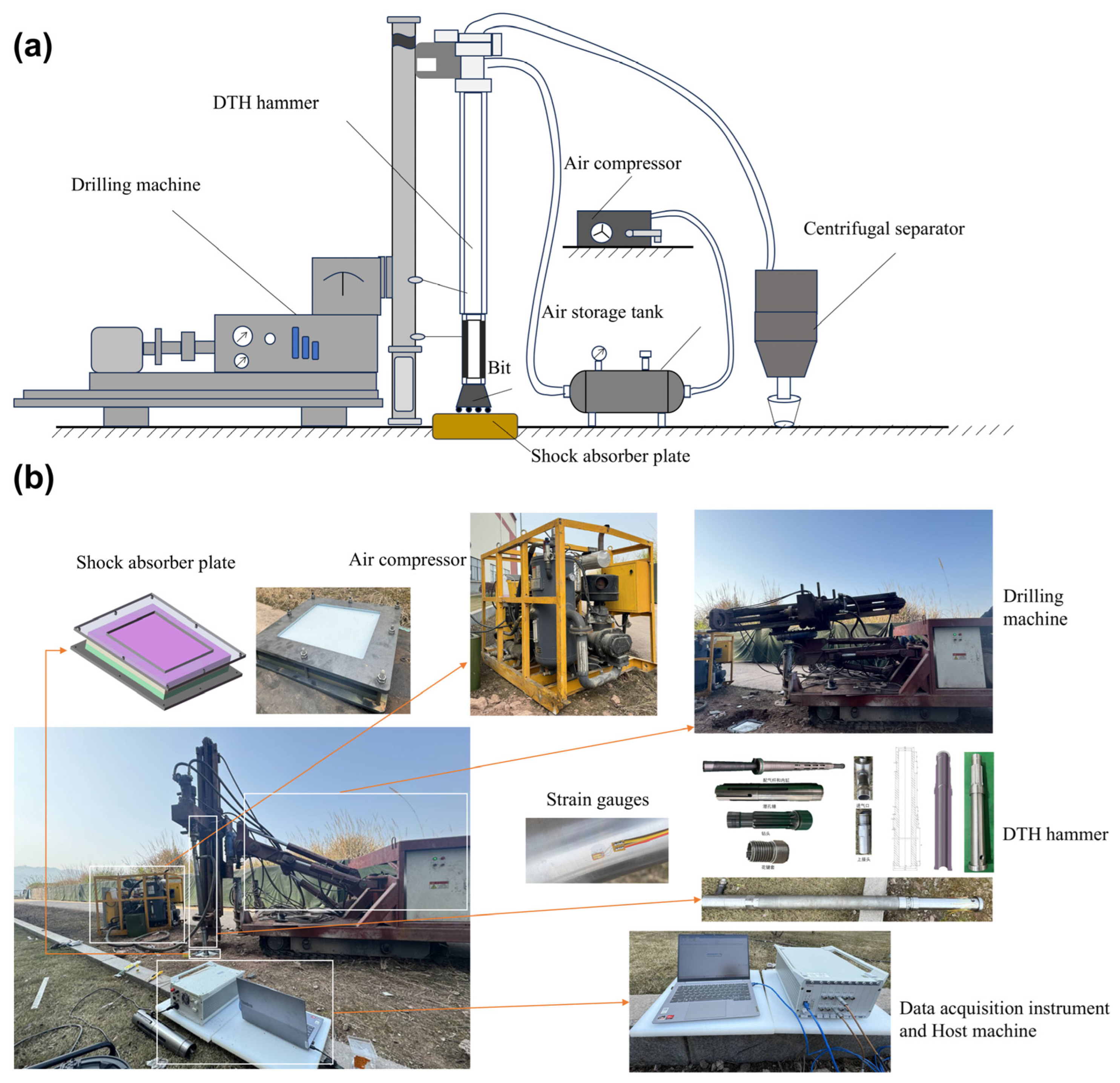
2. Description of the RC-DTH Air Hammer

2.1. The Components of the RC-DTH Air Hammer

As depicted in Figure 2, the valve structure of the DTH hammer is categorized into two distinct types based on the direction of compressed air entering the cylinder as follows: the internal flow structure and the outflow structure. In the outflow piston structure (Figure 2a), compressed air is directed into the cylinder either through the outer tube or via a valve rod separate from the outer tube. Upon reaching a predetermined stroke, the piston’s unique external contour design is engineered to either seal or expose the flow channel’s inlet and outlet. This mechanism facilitates the transfer of high-pressure gas between the upper and lower chambers of the cylinder, thereby enabling the switching action necessary for the hammer’s operation. However, the outflow piston design features slots only on the outer ring of the piston, resulting in a relatively stable overall structure. This design necessitates the structural collaboration with the outer cylinder of the DTH hammer. Consequently, it tends to exhibit areas of structural weakness, and the surface area available for compression is also restricted. In the internal flow piston design (Figure 2b), the compressed air is channeled into the cylinder either through the inner tube or via a valve rod that is distinct from the inner tube. The air distribution channel is integrated within the piston. At a specific stroke point, the configuration of the inner tube and the piston’s flow channel undergoes a change, facilitating the transition of high-pressure gas between the cylinder’s upper and lower compartments. The internal flow piston structure works in tandem with the valve rod, thereby diminishing the need for structural coordination with the outer cylinder. This design also optimizes the area of the compression surface, maximizing its effective size. The comparative analysis of the two structures reveals that the internal flow piston design boasts superior impact energy and structural integrity. It holds the potential for enhancing efficiency and extending the service life of the RC-DTH hammer during drilling operations in complex geological settings.

2.2. Impact Process of the RC-DTH Air Hammer

The initial position of the piston within the RC-DTH (Reverse Circulation-Down-The-Hole) air hammer is situated at the base of the cylinder, subject to the persistent influence of gravitational force. The pivotal structural parameters that dictate the design of the piston for the RC-DTH hammer are identified and denoted as R1, F1, R2, and F2. R1 represents the intake stroke of the lower chamber and is a crucial parameter that defines the valve stroke of the RC-DTH hammer’s piston structure. F1 denotes the intake stroke of the upper chamber. F2 refers to the outgassing stroke of the upper chamber. R2 represents the exit stroke of the lower chamber.
Figure 3 illustrates the single impact cycle of the piston within the RC-DTH (Reverse Circulation-Down-The-Hole) air hammer, detailing the successive stages comprising a full operational cycle. The compressed gas is channeled into the flow channel of the central pipe from the drill pipe, entering via the upper joint. The upper portion of the central pipe serves as the gas inlet, while the lower portion acts as the gas outlet. During the ascending phase, as the piston is at the starting position (stroke length L equals zero), air begins to flow into the lower chamber through the inlet, traversing the passage within this chamber. Upon reaching L = R1, the lower chamber is isolated from the inlet, sealing it off, and the high-pressure air within commences expansion. As L advances to F2, the upper chamber is sealed. Upon reaching L = F1, air is introduced to the upper chamber through its dedicated flow path. Simultaneously, the piston’s velocity diminishes due to the combined effects of pressure within the upper chamber and the ongoing expansion in the lower chamber. When L = R2, the lower chamber reconnects to the outlet, facilitating a rapid decline in the work performed by internal expansion. At the stroke L = Ls (intake cessation point), the upper chamber is sealed, and the piston decelerates to a stop, marking the onset of its return stroke. The flow channel dynamics during the return process are consistent with those during the ascending process. Upon returning to its starting position, the piston finishes a complete cycle of impact.
Through a comparative analysis of the internal and external flow piston structures and utilizing the mathematical model of the piston valve stroke, this study introduces a Type B internal RC-DTH air hammer piston design, as depicted in Figure 4. In contrast to the GQ89 RC-DTH air hammer, which utilizes an outflow piston structure, the Type B model theoretically offers several advantages as follows: It maximizes the compression surface area of both the upper and lower chambers while minimizing the structural requirements to accommodate the outer cylinder. The adoption of a central gas supply method effectively minimizes fluid flow losses and addresses potential structural strength deficiencies in the fitting components. Furthermore, the Type B model streamlines the piston structure design, resulting in reduced mass and enhanced efficiency in converting the internal energy of compressed air into usable work. The detailed parameters for the GQ89 and the Type B RC-DTH air hammer are presented in Table 1.

3. Numerical Methodology and Procedure

The CFD simulations utilized the dynamic mesh technique, and a user-defined function was integrated into the ’ANSYS Fluent2023.R1’ software. This modification enabled the calculation of cell positions, velocities, and accelerations at each time step, which were then employed in functions to determine the pressure-induced loads within the model.

3.1. Selection of the Turbulence Model

To simulate the system, we utilized a pressure-based numerical solver with air as the working fluid. Considering the compressibility of air, it was modeled as a compressible ideal gas. Boundary conditions were set as a pressure inlet and a pressure outlet, in accordance with the specific flow dynamics observed within the RC-DTH hammer cylinder. The standard k-ε turbulence model [57] was employed for this numerical simulation. Due to the simplicity of the piston’s movement in the cylinder, the standard k-ε turbulence model effectively characterizes the turbulent effects and provides an accurate representation of the gas flow dynamics inside the RC-DTH hammer.

3.2. Governing Equations for Flow

The behavior of compressible flows can be characterized using the equations for the conservation of mass and momentum.
Mass conservation:
ρ t + ( ρ υ ) = 0
Momentum conservation:
t ( ρ υ ) + ( ρ υ υ ) = p + ( τ ¯ ¯ ) + ρ g + F
where ρ is the density, υ is the mean velocity, p is the static pressure, ρ g is the gravitational body force, and F is the external body forces. Stress tensor τ ¯ ¯ is given as follows:
τ ¯ ¯ = μ ( υ + υ T ) 2 3 υ I
where μ is the molecular viscosity, I is the unit tensor, and the second term on the right-hand side is the effect of volume dilation.
Additionally, taking into account the conservation of energy, the comprehensive form of the governing equations is expressed as follows:
( ρ ϕ ) t + d i v ( ρ μ ϕ ) = d i v ( Γ g r a d ϕ ) + S
where ϕ denotes the dependent variable, μ denotes the velocity vector, Γ denotes the diffusion coefficient, and S is the general source term.
In the Spalart–Allmaras model, the transported variable, v ˜ , is the turbulent kinematic viscosity, with the exception of the near-wall region. The transport equation form v ˜ is
v ˜ t + x i ( ρ v ˜ u i ) = G v + 1 σ v ˜ x j ( μ + ρ v ˜ ) v ˜ x j + C b 2 ρ v ˜ x j 2 Y ν + S v ˜
where G v is the production of turbulent viscosity, Y ν is the destruction of turbulent viscosity occurring in the near-wall region, σ v ˜ and C b 2 are constants, ν is the molecular kinematic viscosity, and S v ˜ is a user-defined source term.

3.3. Governing Equation for Piston Movement

The primary forces acting on the piston are gravity and pressure-induced forces. Secondary forces, including body forces, flow-induced forces, and frictional forces, are negligible in this calculation. The force balance for the piston is described by Newton’s second law as follows:
m d 2 X d t 2 = P r s A r s P m s A m s + P f s A f s + P f e A f e P r e A r e m g
where A r s is the displacement area of the rear step surface of the piston, A m s is the displacement area of the mid step surface of piston, A f s is the displacement area of the front step surface of the piston, A f e is the displacement area of the front end face of the piston, and P r e is the displacement area of the rear end face of the piston. P r s , P m s , P f s , P f e , and P r e are the corresponding pressure differences acting on the areas. Additionally, m is the piston mass, and g is the acceleration of gravity, i.e., g = 9.80 m/s2.
When the piston reaches the end of its stroke and impact occurs, the rebound velocity v of the piston is calculated as follows:
v = k v i
where k is the rebound coefficient; v i is the piston impact velocity.
When the time step is sufficiently small, the piston acceleration is assumed to be constant within each time step. Consequently, the piston velocity v n + 1 for the (n + 1)th time step can be determined as follows:
v n + 1 = v n + a n Δ t
where a n is the (n + 1)th time step acceleration of the piston.
Furthermore, the piston displacement X n + 1 for the (n + 1)th time step can be obtained from the following:
X n + 1 = X n + υ n + υ n + 1 2 Δ t = X n + υ n Δ t + a n Δ t 2 2

3.4. Computational Domain

Figure 5 illustrates the model subdivided into several key regions according to different basin properties as follows: the upper cavity, lower cavity, inlet flow channel, outlet flow channel, and the fluid within the piston’s inner flow channel. In order to increase the calculation accuracy and reduce the calculation time, the grid of each basin is divided into the hexahedral grid under a fine design, and the total number is 1.795 million. A circular cylindrical, penetrating layer with a thickness of 0.01 mm is introduced between the channels to ensure the convergence of the fluid continuity equation during computation. While the piston moves, the fluid within the upper and lower cavities experiences either compression or tension. The lower end face of the upper cavity and the upper end face of the lower cavity serve as the load-bearing surfaces. The fluid in the piston’s flow channel is associated with a moving grid, while the upper and lower cavities are represented by deformation grids. The fluid within each domain synchronizes with the piston’s movement. The surface grids within each region are designated as the stress surface, deformation surface, wall, interface, inlet, and outlet. Ideal gas is used to simulate the internal fluid of the piston, whose parameters are shown in Table 2.
In the process of grid independence verification, the fluid domain was divided according to different mesh sizes, and the following four different mesh numbers were obtained: 553,000, 806,000, 1.201 million, and 1.795 million. Then, the variation trend of the final impact velocity of the plunger piston under different mesh numbers was analyzed. As shown in Figure 6, different mesh numbers have certain effects on the final impact velocity and impact frequency of the hammer. When the mesh number is close to 1.795 million, the final impact velocity of the piston and the time required to reach its velocity are very close, and the calculated results tend to be stable. When the number of grids reaches about 1.8 million, the effect of the number of grids on the calculation results is almost negligible.

3.5. User-Defined Function and Solver Setting

For this study, a user-defined function, developed in a parallelized format, is utilized to depict the movement of the fluid dynamics grid. The program describes how the rigid body piston is moved by the pressure difference across the two surfaces and specifies the parameters of the piston, including its mass, gravitational acceleration, maximum stroke length, final velocity rebound ratio, initial displacement, velocity, and acceleration. In the simulation, the “DEFINE_CG_MOTION” macro command is employed to define the distinctive movement trajectory of the piston’s center of gravity.
In the numerical experiment conducted, a solver grounded in the pressure-based methodology was employed. This solver incorporates the coupled pressure–velocity coupling technique as its fundamental discrete control equation for the effective management of flow dynamics. The convergence criterion is based on the observation of the change in the residual, and usually the reduction in the residual to three orders of magnitude of the original value can be considered to have converged. We tighten the energy parameters to a threshold of 10−6, while all other criteria are maintained at a threshold of 10−3.
The transient calculation is initialized with the results from the steady-state computation, and the transient time step is typically set within a range of 0.001 s. However, due to the high impact frequency of the RC-DTH hammer, the flow channel state within the cylinder undergoes six changes per cycle. This complexity significantly increases the challenge of achieving convergence, necessitating a reduction in the time step to 0.0001. Because of the short closing stage of the inlet when the piston is moving, the calculation of the pressure continuity equation cannot converge. To ensure that the fluid domain computation converges, we specify the maximum number of iteration steps, set to 2000, to ensure that the computation is pushed toward convergence when the normal criteria for convergence are not met. Within the Fluent, the pressure contour plot of the primary section is saved every eighth time step to track the piston’s movement throughout its cycle, as depicted in Figure 7.

4. Results and Discussion

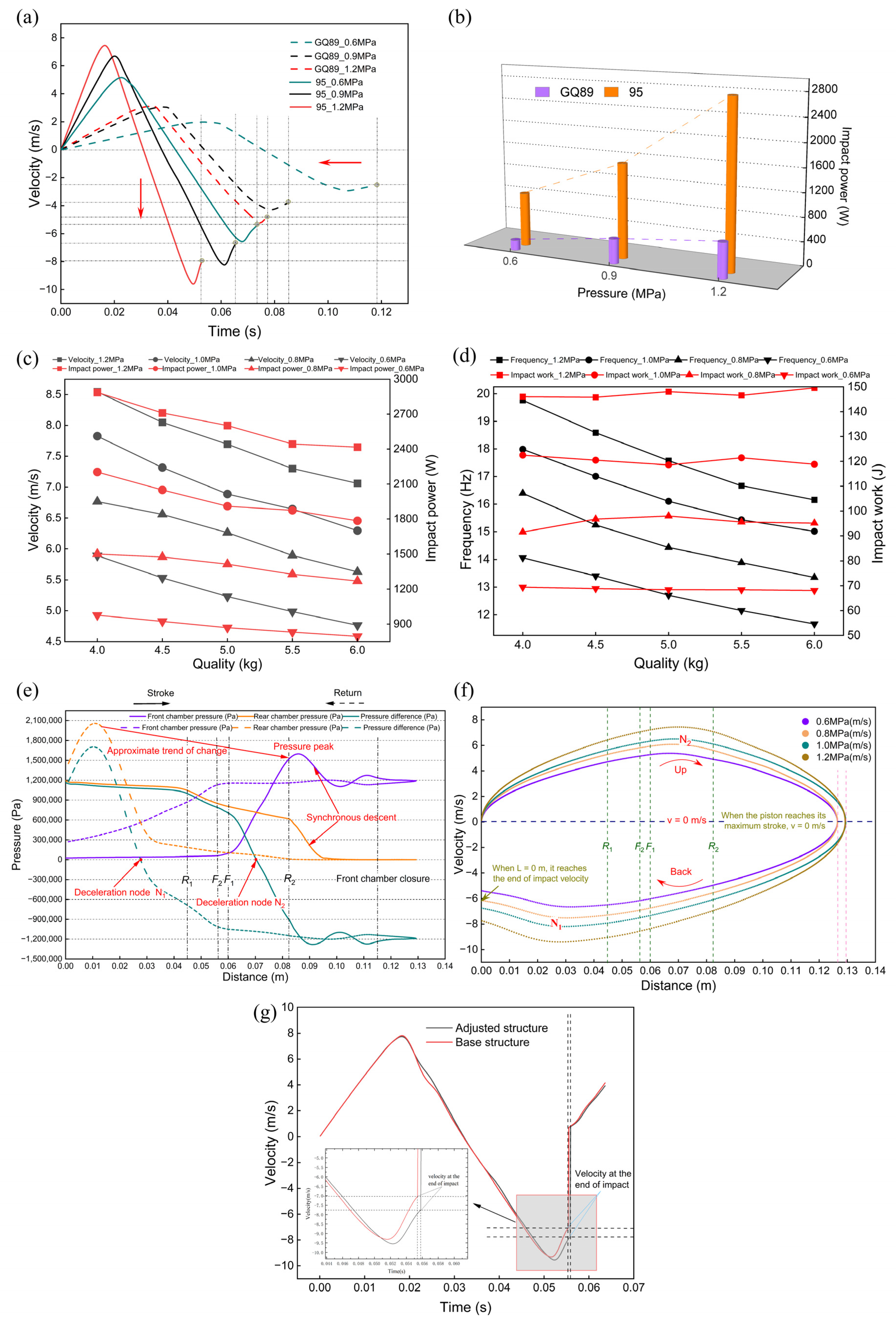
4.1. Impact Performance Comparison

In this part of the study, we conducted a comparative analysis of the impact performance of the GQ89 and Type B RC-DTH air hammer piston at various inlet pressure settings, as shown in Figure 8a. The Type B RC-DTH air hammer exhibits significant advantages in impact velocity and frequency, indicating a qualitative improvement over the GQ89 model. Increasing the inlet pressure markedly enhances the impact performance of the RC-DTH hammer, notably increasing its final impact speed and frequency.
As depicted in Figure 8b, the Type B hammer exhibits a substantially higher impact power compared to the GQ89 model under all pressure conditions examined. Moreover, as the inlet pressure for the piston is elevated, the Type B hammer demonstrates a steeper growth rate in impact power relative to the GQ89 model. The detailed data comparison indicates that at a piston inlet pressure of 0.6 MPa, the single impact energy of the Type B RC-DTH hammer is 229.8% higher than that of the GQ89 model. Simultaneously, the impact power of the Type B RC-DTH hammer experiences a significant increase of 429.9% compared to the GQ89 model. At a piston inlet pressure of 0.9 MPa, the single impact energy increases by 215%, while the impact power increases by 312%. When the piston inlet pressure is raised to 1.2 MPa, the single impact energy increases by 196%, and the impact power increases by 373%.

4.2. Influence of Piston Quality

The impact simulation model for the Type B RC-DTH air hammer has been executed under a range of pressure and quality conditions to derive the key performance parameters. The simulation outcomes for the RC-DTH hammer include the following: impact energy, impact frequency, impact final velocity, and impact power. Figure 8c illustrates that across different pressure settings, there is a consistent trend as follows: as the quality of the RC-DTH hammer’s piston increases, both the final impact velocity and the power of the piston’s strike decrease in a nearly linear fashion. This decline can be attributed to the reduction in impact frequency. Figure 8d indicates that the quality factor exerts a negligible influence on impact energy. Moreover, the variation in impact power is in close agreement with the changes in impact frequency. An explanation for this observation is the following: the reduction in impact energy due to a decrease in impact velocity is compensated for by the enhancement in quality.

4.3. Influence of Valve Stroke Parameters

Figure 8e,f illustrates that the single-cycle motion of the RC-DTH hammer piston is segmented into five distinct stages by F1, F2, R1, and R2. During these stages, the pressure and velocity within the upper and lower chambers exhibit pronounced and characteristic changes.
The intake stroke in the lower chamber (R1) is instrumental in extending the stroke length and rapidly boosting the piston’s speed during its movement. However, as the piston stroke length extends, the rate of acceleration progressively declines, and the incremental advantage of increasing R1 diminishes. An enhancement in R1 leads to a lengthening of the single cycle time, which in turn decreases the frequency of impacts. During the piston’s return movement, a deceleration point, N1, is identified within the 0 to R1 stroke range. At this specific point, the piston’s speed reaches its maximum absolute value. Following N1, the speed starts to decrease until it reaches the final impact speed. As such, the value at the N1 node is inversely related to the final impact speed; a higher value at N1 corresponds to a lower final impact speed. Moreover, the value at N1 has a direct relationship with R1. In essence, within a specific range, the impact performance of the piston shows a negative correlation with the value of R1.
The outgassing stroke in the upper chamber (F2) marginally reduces the overall stroke during the piston’s forward movement, slightly diminishing the final impact velocity while slightly increasing the impact frequency. During the piston’s return phase, the downward acceleration decreases within the F2 to R1 range, affecting the return speed. Consequently, an extension of the F2 stroke negatively impacts the piston’s overall impact performance.
The intake stroke in the upper chamber (F1) establishes the location of the deceleration node N2 during the piston’s forward stroke, and the total stroke length increases substantially as F1 is augmented. During the piston’s return movement, an increase in F1 leads to a slight decrease in the piston’s speed, although this effect is relatively minor. Overall, the impact performance of the piston exhibits a positive correlation with the value of F1.
The outgassing stroke in the lower chamber (R2) contributes to an increase in the piston’s stroke during the stroke process. As the piston returns, the acceleration benefit derived from the stroke diminishes as the stroke length decreases. Consequently, the value of R2 is directly proportional to the impact performance of the piston, indicating that an increase in R2 generally enhances the piston’s impact performance.

4.4. Structural Adjustment

We modify the piston valve stroke of the Type B RC-DTH air hammer, with an adjustment range of 5 mm, as shown in Table 3. The final impact velocity of the piston in the hammer has increased following the adjustment, thereby resulting in the notable enhancement of its impact performance.
By inputting the single-impact time and the final impact velocity of the RC-DTH hammer from before and after the structural adjustments, the impact performance parameters are calculated. The results are presented in Table 4. The modifications to the piston valve stroke, which constitute less than 11.2% of the hammer’s structural parameters, have led to a notable enhancement in impact power by 20.32%. The numerical simulation findings confirm the superior impact performance of the Type B RC-DTH air hammer over the GQ89 hammer. Furthermore, these results validate the precision of the theoretical analysis conducted on the gas distribution stroke parameters.

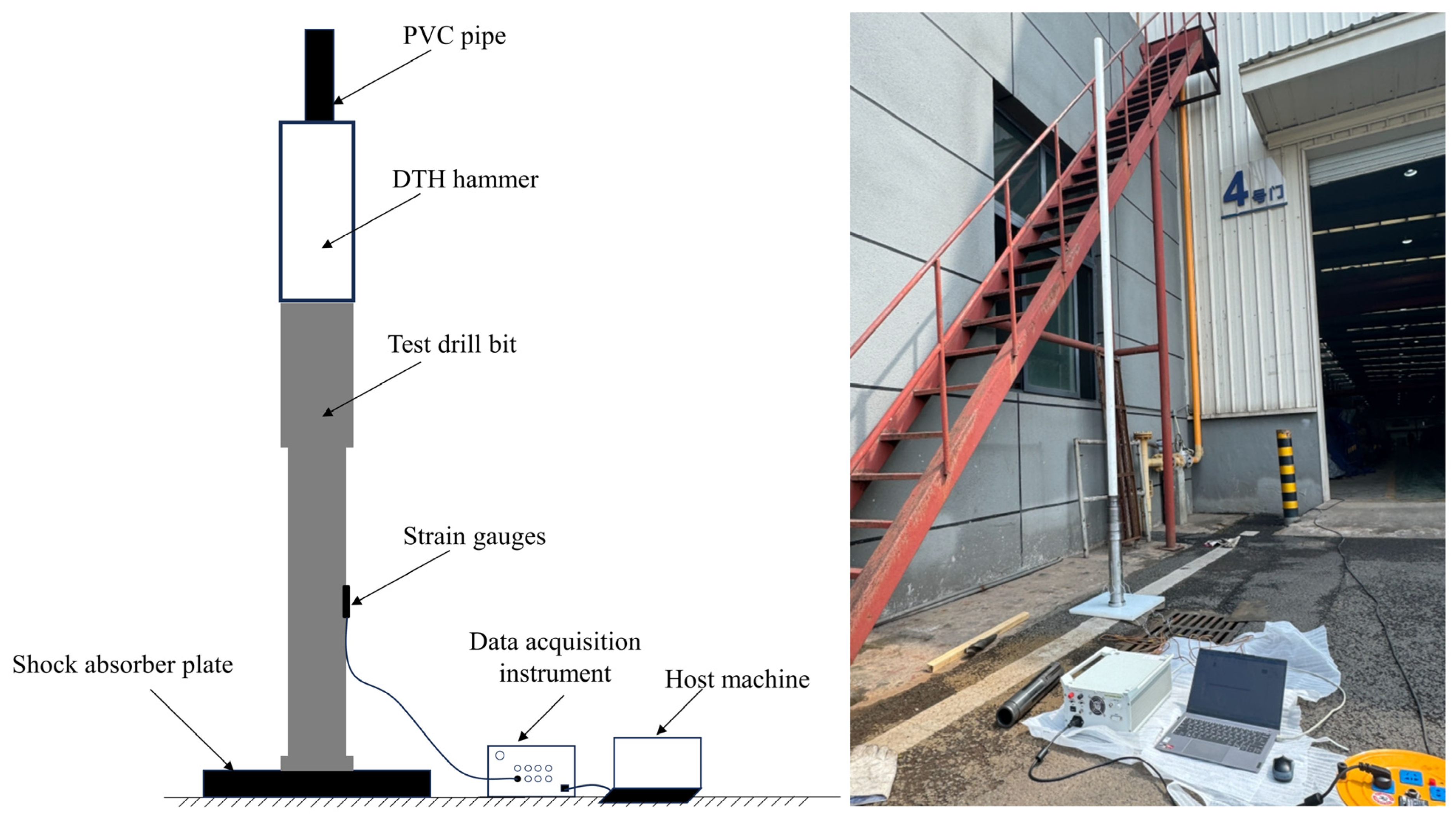
4.5. Confirmatory Experiments

To validate the accuracy of the simulated piston impact energy for the Type B RC-DTH air hammer, an experimental setup was constructed to measure the actual piston impact energy. The impact performance testing system, designed using the stress wave technique, consists of the following two main components: a data acquisition and analysis system and a drilling rig system. The drilling rig system is made up of a drilling apparatus, an air compressor, a damping plate, and a specialized test bit. The data acquisition and analysis system are equipped with instruments for capturing stress waves and oscillographic data, a host computer, dedicated analysis software, and a strain gauge for precise measurements.
Figure 9 illustrates the testing methodology of the drop hammer calibration experiment. The piston is elevated to set heights of 1.0 m, 1.4 m, and 1.8 m, and it is then released to freely strike the test bit. The strain wave produced by the impact is captured by a strain gauge, and this procedure is carried out four times for each height. We postulate a linear correlation between the piston’s impact energy and the peak strain values. Consequently, the data from each height are analyzed and compared, with any peaks that are exceptionally high or low being discarded. The average of the remaining peak values is calculated, and the equations representing these values are solved in pairs to determine the average coefficients ‘a’ and ‘b’ of the linear relationship.
Based on the data presented in Table 5, the linear equation that correlates the peak of the strain wave with the gravitational potential energy of the piston is as follows:
Q = 1.32 μ 2 163.4
Figure 10 illustrates the assembly of the Type B RC-DTH air hammer within the impact performance real drilling testing system. The air compressor is regulated to maintain an air pressure of 1.2 MPa, while the data sampling is conducted at a frequency of 500 Hz. During the RC-DTH hammer piston impact test, the strain wave generated by the drill bit is captured. The peak value of this strain wave is then used in Equation (10) to compute the impact energy exerted by the piston. The results of these calculations are detailed in Table 6.
The experimental findings reveal that the Type B RC-DTH air hammer’s piston impact energy is roughly 285.33 J, with the final impact velocity of the piston estimated to be 10.83 m/s and an impact frequency of approximately 18 Hz. The numerical simulation, on the other hand, yields an impact energy of 148.0326 J and an impact frequency of 17.5747 Hz. The measured impact frequency is essentially consistent with the simulated frequency, and the impact energies are of a similar order of magnitude. This agreement suggests that the numerical model for the impact performance of the RC-DTH hammer is reliable and meets the anticipated standards of accuracy. In the RC-DTH hammer impact simulation model, it is imperative to set up a thin layer grid that connects the individual grids across different regions. This setup leads to a certain degree of gas pressure loss during the computational process, which in turn translates to a loss in impact energy within the simulation.
The impact frequency of the Type B RC-DTH air hammer is similar to that of the GQ89 DTH hammer. However, the Type B model exhibits an impact energy that is 1.84 times greater and an impact power that is 1.74 times higher than the GQ89 model, demonstrating considerable performance enhancements. These results confirm the superior performance of the Type B RC-DTH air hammer as introduced in this paper and validate the effectiveness of the proposed gas distribution design.

5. Conclusions

This work presented a mathematical model describing the behavior of the piston across various motion stages of the RC-DTH air hammer. Additionally, it outlined the design of the piston structure for the Type B internal flow RC-DTH air hammer. Utilizing CFD dynamic mesh technology, a numerical model for simulating the piston impact of the RC-DTH hammer was developed to assess the impact performance of the piston. An impact performance testing platform for the RC-DTH air hammer was constructed to validate the accuracy of the numerical simulation outcomes. The following conclusions were drawn from this study:
  • Enhancing the intake stroke of the upper chamber (F1) and the outlet stroke of the lower chamber (R2) of the RC-DTH air hammer piston effectively improves the piston’s impact performance. Conversely, increasing the inlet stroke of the lower chamber (R1) and the outlet stroke of the upper chamber (F2) tends to diminish the piston’s impact performance.
  • The mass of the piston in the RC-DTH air hammer influences its striking frequency, while having a minimal impact on the energy of each blow. As the mass of the piston increases, the impact power diminishes.
  • After optimizing the piston valve stroke parameters of the Type B RC-DTH air hammer, its impact performance improved by 20.32%. Compared to the GQ89 hammer, the Type B hammer exhibits an 84% increase in impact energy and a 74% increase in impact power. Additionally, the impact energy test conducted on the RC-DTH hammer confirms the validity of the numerical simulation results derived from the impact simulation model.

Author Contributions

Z.L.: Writing—original draft, Writing—review and editing, Software, Investigation. Y.L.: Writing—original draft, Writing—review and editing, Validation, Software, Investigation, Methodology. W.H.: Formal analysis, Software, Methodology. R.T.: Resources, Project administration, Supervision. J.H.: Resources, Conceptualization, Validation. Y.S.: Project administration, Supervision, Resources. H.C.: Formal analysis, Resources, Validation. Q.H.: Resources, Supervision, Validation. All authors have read and agreed to the published version of the manuscript.

Funding

This work is financially supported by the Key Research and Development Program of the Ningxia Hui Autonomous Region (Grant No. 2022BEG02015), which is gratefully acknowledged. The authors also thank the editor and anonymous reviewers for their valuable advice.

Institutional Review Board Statement

Not applicable.

Informed Consent Statement

Not applicable.

Data Availability Statement

Data will be made available on request.

Conflicts of Interest

Author Rui Tao and Yongliang Sun were employed by the company Ningxia Institute of Mineral Geological Survey, Ningxia, China. Author Hongwei Chen was employed by the company China national gold engineering, Beijing, China. The remaining authors declare that the research was conducted in the absence of any commercial or financial relationships that could be construed as a potential conflict of interest.

References

  1. Zhu, L.; Huang, Y.; Wang, R.; Wang, J. A mathematical model of the motion of cutting particles in reverse circulation air drilling. Appl. Math. Comput. 2015, 256, 192–202. [Google Scholar] [CrossRef]
  2. Richard, T.; Germay, C.; Detournay, E. A simplified model to explore the root cause of stick-slip vibrations in drilling systems with drag bits. J. Sound Vib. 2015, 305, 432–456. [Google Scholar] [CrossRef]
  3. Milkov, A.V. Pre-drill Assessments and Drilling Outcomes in Mexico in 2018–2022 and Historical Experience from Norway and the Netherlands: Lessons Learned and Recommendations for Future Petroleum Exploration. Nat. Resour. Res. 2022, 31, 2483–2504. [Google Scholar] [CrossRef]
  4. Pavlovskaia, E.; Hendry, D.C.; Wiercigroch, M. Modelling of high frequency vibro-impact drilling. Int. J. Mech. Sci. 2015, 91, 110–119. [Google Scholar] [CrossRef]
  5. Li, X.; Gong, F.; Tao, M.; Dong, L.; Du, K.; Ma, C.; Zhou, Z.; Yin, T. Failure mechanism and coupled static-dynamic loading theory in deep hard rock mining: A review. J. Rock Mech. Geotech. 2007, 9, 767–782. [Google Scholar] [CrossRef]
  6. Kwon, K.B.; Song, C.H.; Park, J.Y.; Oh, J.Y.; Lee, J.W.; Cho, J.W. Evaluation of Drilling Efficiency by Percussion Testing of a Drill Bit with New Button Arrangement. Int. J. Precis. Eng. Man. 2004, 15, 1063–1068. [Google Scholar] [CrossRef]
  7. Cheng, Z.; Li, G.; Huang, Z.; Sheng, M.; Wu, X.; Yang, J. Analytical modelling of rock cutting force and failure surface in linear cutting test by single PDC cutter. J. Pet. Sci. Eng. 2019, 177, 306–316. [Google Scholar] [CrossRef]
  8. Chiang, L.E.; Elías, D.A. Modeling impact in down-the-hole rock drilling. Int. J. Rock Mech. Min. 2000, 37, 599–613. [Google Scholar] [CrossRef]
  9. Song, H.; Shi, H.; Ji, Z.; Wu, X.; Li, G.; Zhao, H.; Wang, G.; Liu, Y.; Hou, X. The percussive process and energy transfer efficiency of percussive drilling with consideration of rock damage. Int. J. Rock Mech. Min. 2009, 119, 1–12. [Google Scholar] [CrossRef]
  10. Luo, Y.; Peng, J.; Li, L.; He, J.; Gan, X.; Yin, K.; Zhao, Z. Development of a specially designed drill bit for down-the-hole air hammer to reduce dust production in the drilling process. J. Clean. Prod. 2006, 112, 1040–1048. [Google Scholar] [CrossRef]
  11. Xie, D.; Huang, Z.; Ma, Y.; Vaziri, V.; Kapitaniak, M.; Wiercigroch, M. Nonlinear dynamics of lump mass model of drill-string in horizontal well. Int. J. Mech. Sci. 2020, 174, 105450. [Google Scholar] [CrossRef]
  12. Yang, Y.; Zhang, C.; Lin, M.; Chen, L. Research on rock-breaking mechanism of cross-cutting PDC bit. J. Petrol. Sci. Eng. 2018, 161, 657–666. [Google Scholar] [CrossRef]
  13. Zhang, X.; Luo, Y.; Gan, X.; Yin, K. Design and numerical analysis of a large-diameter air reverse circulation drill bit for reverse circulation down-the-hole air hammer drilling. Energy Sci. Eng. 2019, 7, 921–929. [Google Scholar] [CrossRef]
  14. Shi, C.; Zhu, X.; Luo, H. Study of DTH Bit-Rock Interaction Numerical Simulation Method and DTH Bit Properties Evaluation. Arab. J. Sci. Eng. 2017, 42, 2179–2190. [Google Scholar] [CrossRef]
  15. Bu, C.; Qu, Y.; Cheng, Z.; Liu, B. Numerical simulation of impact on pneumatic DTH hammer percussive drilling. J. Earth Sci. 2009, 20, 868–878. [Google Scholar] [CrossRef]
  16. Zhang, X.; Luo, Y.; Fan, L.; Peng, J.; Yin, K. Investigation of RC-DTH air hammer performance using CFD approach with dynamic mesh method. J. Adv. Res. 2009, 18, 127–135. [Google Scholar] [CrossRef]
  17. Zhang, X.; Wu, Z.; Zhao, Z.; Sun, P.; Tang, L.; Shabir, U. Insight into dust control performance of a reverse circulation drill bit using multiphase flow simulation. Eng. Appl. Comp. Fluid Mech. 2022, 16, 841–857. [Google Scholar] [CrossRef]
  18. Menezes, P.L.; Lovell, M.R.; Avdeev, I.V.; Higgs, C.F. Studies on the formation of discontinuous rock fragments during cutting operation. Int. J. Rock Mech. Min. 2014, 71, 131–142. [Google Scholar] [CrossRef]
  19. Deng, Y.; Chen, M.; Jin, Y.; Zhang, Y.; Zou, D.; Lu, Y. Theoretical and experimental study on the penetration rate for roller cone bits based on the rock dynamic strength and drilling parameters. J. Nat. Gas. Sci. Eng. 2016, 36, 117–123. [Google Scholar] [CrossRef]
  20. Liu, X.; Long, X.; Zheng, X.; Meng, G.; Balachandran, B. Spatial-temporal dynamics of a drill string with complex time-delay effects: Bit bounce and stick-slip oscillations. Int. J. Mech. Sci. 2020, 170, 105338. [Google Scholar] [CrossRef]
  21. Strauss, M.F.; Story, S.L.; Mehlhorn, N.E. Applications of Dual-Wall Reverse-Circulation Drilling in Ground-Water Exploration and Monitoring. Groundw. Monit. Remediat. 1989, 9, 63–71. [Google Scholar] [CrossRef]
  22. Franca, L.E.P. A bit-rock interaction model for rotary-percussive drilling. Int. J. Rock Mech. Min. 2011, 48, 827–835. [Google Scholar] [CrossRef]
  23. Luo, Y.; Li, L.; Peng, J. Detection of multilayer cavities by employing RC-DTH air hammer system and cavity auto scanning laser system. Arch. Min. Sci. 2015, 60, 1041–1052. [Google Scholar] [CrossRef]
  24. Hashiba, K.; Fukui, K.; Liang, Y.; Koizumi, M.; Matsuda, T. Force-penetration curves of a button bit generated during impact penetration into rock. Int. J. Impact Eng. 2015, 85, 45–56. [Google Scholar] [CrossRef]
  25. Tkalich, D.; Yastrebov, V.A.; Cailletaud, G.; Kane, A. Multiscale modeling of cemented tungsten carbide in hard rock drilling. Int. J. Solids Struct. 2017, 128, 282–295. [Google Scholar] [CrossRef]
  26. Zhao, Z.; Meng, Y.; Li, L.; Shi, X.; Xiang, C. Effects of Working Angle on Pneumatic Down-the-hole Hammer Drilling. Rock Mech. Rock Eng. 2015, 48, 2141–2155. [Google Scholar] [CrossRef]
  27. Lundberg, B.; Collet, P. Optimal wave with respect to efficiency in percussive drilling with integral drill steel. Int. J. Impact Eng. 2010, 37, 901–906. [Google Scholar] [CrossRef]
  28. Liao, M.; Liu, Y.; Chávez, J.P.; Chong, A.S.E.; Wiercigroch, M. Dynamics of vibro-impact drilling with linear and nonlinear rock models. Int. J. Mech. Sci. 2018, 146, 200–210. [Google Scholar] [CrossRef]
  29. Malard, F.; Datry, T.; Gibert, J. Subsurface sediment contamination during borehole drilling with an air-actuated down-hole hammer. J. Contam. Hydrol. 2005, 79, 156–164. [Google Scholar] [CrossRef] [PubMed]
  30. Lundberg, B.; Okrouhlik, M. Efficiency of a percussive rock drilling process with consideration of wave energy radiation into the rock. Int. J. Impact Eng. 2006, 32, 1573–1583. [Google Scholar] [CrossRef]
  31. Yin, Q.; Peng, J.; Bo, K.; He, J.; Kui, Y.; Gan, X. Study on dust control performance of a hammer drill bit. Int. J. Min. Reclam. Env. 2013, 27, 393–406. [Google Scholar] [CrossRef]
  32. Wang, S.; Li, X.; Yao, J.; Gong, F.; Li, X.; Du, K.; Tao, M.; Huang, L.; Du, S. Experimental investigation of rock breakage by a conical pick and its application to non-explosive mechanized mining in deep hard rock. Int. J. Rock Mech. Min. 2019, 122, 104063. [Google Scholar] [CrossRef]
  33. Depouhon, A.; Denoël, V.; Detournay, E. Numerical simulation of percussive drilling. Int. J. Numer. Anal. Met. 2015, 39, 889–912. [Google Scholar] [CrossRef]
  34. Cao, P.; Cao, H.; Cao, J. Performance of large-diameter pneumatic down-the-hole (DTH) hammers: A focus on influences of the hammer structure. Petrol. Sci. 2023, 20, 2399–2412. [Google Scholar] [CrossRef]
  35. Guo, B.; Gao, D. New development of theories in gas drilling. Petrol. Sci. 2013, 10, 507–514. [Google Scholar] [CrossRef]
  36. Ajibose, O.K.; Wiercigroch, M.; Akisanya, A.R. Experimental studies of the resultant contact forces in drillbit-rock interaction. Int. J. Mech. Sci. 2015, 91, 3–11. [Google Scholar] [CrossRef]
  37. Gao, M.; Yang, B.; Xie, J.; Ye, S.; Liu, J.; Liu, Y.; Tang, R.; Hao, H.; Wang, X.; Wen, X.; et al. The mechanism of microwave rock breaking and its potential application to rock-breaking technology in drilling. Petrol. Sci. 2022, 19, 1110–1124. [Google Scholar] [CrossRef]
  38. Chiang, L.E.; Stamm, E.B. Design optimization of valveless DTH pneumatic hammers by a weighted pseudo-gradient search method. J. Mech. Des. 1998, 120, 687–694. [Google Scholar] [CrossRef]
  39. Li, X.; Rupert, G.; Summers, D.A.; Santi, P.; Liu, D. Analysis of impact hammer rebound to estimate rock drillability. Rock Mech. Rock Eng. 2000, 33, 1–13. [Google Scholar] [CrossRef]
  40. Bo, K.; Sun, S.; Hu, Y.; Wang, M. Design Optimization and Performance Analysis of the Pneumatic DTH Hammer with Self-Propelled Round Bit. Shock Vib. 2021, 2021, 1–13. [Google Scholar] [CrossRef]
  41. Bo, K.; Chen, B.; Hu, Y.; Wang, M. Design optimization and feasibility analysis of pneumatic DTH Hammer with self-rotation bit. J. Vibroeng. 2022, 24, 305–316. [Google Scholar] [CrossRef]
  42. Kim, D.J.; Oh, J.Y.; Cho, J.W.; Kim, J.; Chung, J.; Song, C. Design study of impact performance of a DTH hammer using PQRSM and numerical simulation. J. Mech. Sci. Technol. 2019, 33, 5589–5602. [Google Scholar] [CrossRef]
  43. Richard, T.; Germay, C.; Detournay, E. Self-excited stick-slip oscillations of drill bits. Comptes Rendus Mec. 2004, 332, 619–626. [Google Scholar] [CrossRef]
  44. Zhang, H.; Song, H.; Kang, Y.; Huang, G.; Qu, C. Experimental Analysis on Deformation Evolution and Crack Propagation of Rock Under Cyclic Indentation. Rock Mech. Rock Eng. 2013, 46, 1053–1059. [Google Scholar] [CrossRef]
  45. Wang, M.; Bai, L.; Wang, L.; Qiu, S.; Tian, W.; Su, G. Thermal hydraulic and stress coupling analysis for ap1000 Pressurized Thermal Shock (PTS) study under SBLOCA scenario. Appl. Therm. Eng. 2017, 122, 158–170. [Google Scholar] [CrossRef]
  46. Niu, Q.; Wang, N. Study of heat transfer by using DEM-CFD method in a randomly packed pebble-bed reactor. Nucl. Sci. Tech. 2019, 30, 28. [Google Scholar] [CrossRef]
  47. Marschall, K.J.; Mleczko, L. CFD Modeling of an internally circulating fluidized bed reactor. Chem. Eng. Sci. 1999, 54, 2085–2093. [Google Scholar] [CrossRef]
  48. Rahimi, M.; Parvareh, A. CFD study on mixing by coupled jet-impeller mixers in a large crude oil storage tank. Comput. Chem. Eng. 2007, 31, 737–744. [Google Scholar] [CrossRef]
  49. Zhang, Z.; Li, J.; Tian, J.; Dong, R.; Zou, Z.; Gao, S.; Tan, D. Performance, combustion and emission characteristics investigations on a diesel engine fueled with diesel/ethanol/n-butanol blends. Energy 2002, 249. [Google Scholar] [CrossRef]
  50. Zhong, H.; Wei, Z.; Man, Y.; Pan, S.; Zhang, J.; Niu, B.; Yu, X.; Ouyang, Y.; Xiong, Q. Prediction of instantaneous yield of bio-oil in fluidized biomass pyrolysis using long short-term memory network based on computational fluid dynamics data. J. Clean. Prod. 2023, 391, 136192. [Google Scholar] [CrossRef]
  51. Salehi, S.; Madani, S.A.; Kiran, R. Characterization of drilling fluids filtration through integrated laboratory experiments and CFD modeling. J. Nat. Gas Sci. Eng. 2016, 29, 462–468. [Google Scholar] [CrossRef]
  52. Wu, D.; Zhang, S.; He, Y. A dynamic mesh-based approach to analyse hydrodynamic interactions between a fluidic hammer and drill bit. J. Petrol. Sci. Eng. 2019, 175, 536–546. [Google Scholar] [CrossRef]
  53. Zhang, X.; Zhang, S.; Luo, Y.; Wu, D. Experimental study and analysis on a fluidic hammer—An innovative rotary-percussion drilling tool. J. Petrol. Sci. Eng. 2019, 173, 362–370. [Google Scholar] [CrossRef]
  54. Zhang, T.; Yuan, L.; Yang, K.; Liu, Y.; Wei, F.; Yu, X. Modeling of Multiphysical-Chemical Coupling for Coordinated Mining of Coal and Uranium in a Complex Hydrogeological Environment. Nat. Resour. Res. 2021, 30, 571–589. [Google Scholar] [CrossRef]
  55. Cao, W.; Liu, L.; Liu, H.; Lai, F. Investigating the Irregular Localization of Skarn Orebodies by Computational Modeling in the Fenghuangshan Ore Field, Tongling District, Anhui Province, China. Nat. Resour. Res. 2020, 29, 2967–2988. [Google Scholar] [CrossRef]
  56. Ma, J.; Xie, S.; Liu, D.; Carranza, E.; He, Z.; Zhang, M.; Wang, T. Effects of Fe3+ on Dissolution Dynamics of Carbonate Rocks in a Shallow Burial Reservoir. Nat. Resour. Res. 2021, 30, 1291–1303. [Google Scholar] [CrossRef]
  57. Bhatti, M.M.; Ellahi, R. Numerical investigation of non-Darcian nanofluid flow across a stretchy elastic medium with velocity and thermal slips. Numer. Heat Transf. Part B Fundam. 2023, 83, 323–343. [Google Scholar] [CrossRef]
Figure 1. Schematic of the hollow-through DTH air hammer drilling system marked as follows: 1—flexible discharging tube; 2—double-passage swivel; 3—goose neck tube; 4—flexible air input tube; 5—dual-wall drill pipe; 6—check valve; 7—inner tube of the hammer; 8—inner cylinder; 9—piston; 10—sleeve; 11—drill bit.
Applsci 15 00740 g001
Figure 2. Two types of RC-DTH air hammers marked as follows: (a) outflow piston; (b) internal flow piston.
Applsci 15 00740 g002
Figure 3. Impact process of the RC-DTH air hammer. (ae) Represent the backhaul phase and (fi) represent the stroke phase; the end of (e) can be regarded as the initial stage of the stroke phase and the end of (i) as the initial stage of the backhaul phase.
Applsci 15 00740 g003
Figure 4. Structure of the type B RC-DTH air hammer.
Applsci 15 00740 g004
Figure 5. Grid system of the model and associated profile.
Applsci 15 00740 g005
Figure 6. Grid independence verification.
Applsci 15 00740 g006
Figure 7. Group of typical sectional pressure contour.
Applsci 15 00740 g007
Figure 8. Profiles obtained by CFD simulations. (a) Velocity and time curves of two types of hammers under different inlet pressure conditions; (b) impact power under different inlet pressure conditions; (c) influence of RC-DTH hammer quality on impact final velocity and impact power; (d) influence of DTH hammer quality on impact frequency and impact work; (e) correlation between the gas pressure in the upper and lower chambers of the piston with the stroke; (f) correlation between piston motion velocity with piston stroke; and (g) comparison of impact velocity before and after piston structure adjustment.
Applsci 15 00740 g008
Figure 9. Drop hammer calibration method.
Applsci 15 00740 g009
Figure 10. Drill system for testing the impact performance of the RC-DTH air hammers. (a) Schematic diagram; (b) field test.
Applsci 15 00740 g010
Table 1. Partial structural parameters of the GQ89 and the type B RC-DTH air hammer.
TypeOuter Diameter/mmPiston Mass/kgRated Gas Pressure/MPaGas Distribution Stroke/mm
R1F2F1R1
GQ89896.50.6–1.245.5406880
Type B9550.6–1.245576082
Table 2. Fluid physical parameters.
Density/
kg/L
Cp/
J/(kg K)
λ/
W/(m K)
Viscosity/
kg/(m s)
1.0 × 10−31006.430.02421.7894 × 10−5
Table 3. Adjusted valve stroke.
Valve Stroke/mm
R1F2F1R1
Pre-adjustment stroke45576082
Adjusted stroke40526587
Table 4. Comparison of impact performance parameters before and after piston structure adjustment.
Velocity/
m/s
Time/
s
Frequency/
Hz
Impact Work/
J
Impact Power/
W
Base structure7.040.055418.05123.902236.53
Adjusted structure7.750.055817.92150.162690.97
Increase range/%10.090.7−0.721.1920.32
Table 5. Drop hammer experiment record table.
L/mExperiment NumberGravitational Potential Energy/JStrain Peak/μεab
1.0147.6766174.916051.32−163.4
2176.97205
3181.45761
4182.5
1.4166.7472235.8926
2197.1953
3186.3264
4238.8142
1.8185.8179221.22
2245.65
3255.313
4195.313
Table 6. Piston impact performance records.
TestStrain Peak/μεImpact Work/JFrequency/Hz
1532298.465217
2507285.770219
3516290.340418
4522293.387217
5632349.245219
6539302.019818
Disclaimer/Publisher’s Note: The statements, opinions and data contained in all publications are solely those of the individual author(s) and contributor(s) and not of MDPI and/or the editor(s). MDPI and/or the editor(s) disclaim responsibility for any injury to people or property resulting from any ideas, methods, instructions or products referred to in the content.

