Article

Quadrature-Phase-Locked-Loop-Based Back-Electromotive Force Observer for Sensorless Brushless DC Motor Drive Control in Solar-Powered Electric Vehicles

1
Department of Electrical Engineering, Indian Institute of Technology Delhi, New Delhi 110016, India
2
Department of Automation, Electrical and Electronic Engineering and Industrial Informatics, Escuela Técnica Superior de Ingenieros Industriales, Universidad Politécnica de Madrid, 28006 Madrid, Spain
3
Department of Hydraulic, Energy and Environmental Engineering, Escuela Técnica Superior de Ingenieros de Caminos, Canales y Puertos, Universidad Politécnica de Madrid, 28040 Madrid, Spain
*
Author to whom correspondence should be addressed.
Appl. Sci. 2025, 15(2), 574; https://doi.org/10.3390/app15020574
Submission received: 29 November 2024 / Revised: 28 December 2024 / Accepted: 7 January 2025 / Published: 9 January 2025
(This article belongs to the Special Issue Design and Synthesis of Electric Energy Conversion Systems)

Abstract

:
This work presents a sensorless brushless DC motor (BLDCM) drive control, optimized for solar photovoltaic (PV)- and battery-fed light electric vehicles (LEVs). A back-electromotive force (EMF) observer integrated with an enhanced quadrature-phase-locked-loop (QPLL) structure is proposed for accurate rotor position estimation, addressing limitations of existing control methods at low speeds and under dynamic conditions. The study replaces the conventional arc-tangent technique with a QPLL-based approach, eliminating low-pass filters to enhance system adaptability and reduce delays. The experimental results demonstrate a significant reduction in commutation error, with a nearly flat value at 0 degrees during steady-state and less than 8 degrees under dynamic conditions. Furthermore, the performance of a modified single-ended primary-inductor converter (SEPIC) for maximum power point tracking (MPPT) in solar-powered LEVs is verified, minimizing current ripple and ensuring smooth motor operation. The system also incorporates a regenerative braking mechanism, extending the vehicle’s range by efficiently recovering kinetic energy through the battery with 30.60% efficiency. The improved performance of the proposed method and system over conventional approaches contributes to the advancement of efficient and sustainable solar-powered BLDC motor-based EV technologies.

1. Introduction

1.1. General Context

The global energy crisis and escalating fuel prices have significantly increased interest in electric vehicles (EVs), making them a focal point for research and development. For instance, in India, two- and three-wheeler EVs, including goods carriers, e-bikes, and e-rickshaws, dominate the market. These segments demand efficient, cost-effective motor drive designs that balance performance with affordability [1].
Brushless DC motors (BLDCMs) are commonly used in such EVs, as they provide high power density, efficiency and torque-to-inertia ratio [2]. In recent years, the prices of rare-earth magnet material have decreased significantly, which also favors the deployment of BLDCMs. The main drawback of BLDCMs is the need for position sensors.
To a large extent, the position control of BLDCMs relies on Hall-effect sensors mounted on the motor yoke to estimate rotor position [3]. These sensors detect variations in the magnetic field as rotor poles pass by, providing accurate and reliable position feedback, thereby allowing precise control over the motor’s performance. However, sensors are prone to mechanical wear and environmental factors, especially in harsh conditions [4]. When robust and reliable continuous performance is required, such as automotive applications, sensor-based control methods are usually redundant with sensorless methods. In less critical applications, eliminating sensors allows for notable reductions in system cost and complexity. In fact, the elimination of electromechanical sensors reduces the hardware cost, the installation complexity associated with the cabling, and the system inertia, while increasing reliability, as noise sensitivity issues are avoided.
This paper focuses on sensorless BLDCM drive control for application in solar-powered electric vehicles. Indeed, the integration of solar photovoltaic (PV) arrays into EVs has gained considerable attention, thanks to the development of efficient maximum power point tracking (MPPT) algorithms and the exploration of various DC-DC power converters [5,6]. Conventional boost and buck-boost converters are commonly used for MPPT; however, they often result in high ripple, causing discontinuous input and output currents. The inclusion of input and output inductors in Cuk converters helps reduce current ripple but introduces the challenge of inverting the output polarity, necessitating additional circuitry to sense the negative voltage at the DC bus. While SEPIC and Zeta converter provide non-inverted outputs, the Zeta converter exhibits input current ripple, potentially requiring a small input inductor. Among these, the SEPIC demonstrates favorable transient and dynamic behaviors, making it a promising option [7]. However, its application in solar-PV-fed EVs has not been explored extensively in the literature. This paper aims to introduce a BLDC motor drive powered by a SEPIC for solar-PV-based EV applications.
Furthermore, regenerative braking technology, a crucial component of EV propulsion systems, has been extensively studied in the literature as a means of promoting environmentally friendly transportation. Expanding the driving range by recovering additional kinetic energy has been well documented [8]. However, braking mode involves reversing current direction, which often requires a bidirectional converter. While effective, this approach increases system cost and size [9]. In the case of BLDC motor drives, switching pulses to the voltage source inverter (VSI) can be modified to reverse current direction, enabling regenerative braking without a bidirectional converter. Methods such as single- and dual-boost switching have been developed for energy reversal. In this work, a pulse-width modulation (PWM)-based switching scheme is employed for regenerative braking, where the amount of recovered energy is directly proportional to the modulation index.

1.2. Sensorless Control of BLDCMs

Sensorless control methods for BLDCMs require position estimation techniques [4]. Indirect methods estimate rotor position indirectly by leveraging position-related quantities, such as the back-electromotive force (back-EMF) components or the third harmonic of the back-EMF signal. The most widespread indirect position estimation methods rely on the detection of the zero-crossing points of the back-EMF waveform to generate the virtual Hall signals [10]. Alternatively, the third harmonic component of the back-EMF can be used, which has a constant phase relationship with the rotor flux for any machine operating condition [11]. However, these methods become less accurate at low speeds and standstill conditions [12], which, in fact, also hinder the control during motor starting, requiring open-loop starting procedures. This limitation is due to the reduced amplitude of the back-EMF at low speeds, which leads to an excessively low signal-to-noise ratio of the position-related system states and, consequently, delays detection [13].
To address the limitations of indirect position estimation methods at low speeds, model-based approaches are widely employed for rotor position and speed estimation, especially for medium- and high-speed applications. Among model-based approaches, closed-loop observers are the most prominent [14], designed to drive the observer output to converge with the controlled output, ensuring that the tracking error is brought to zero. Thus, the estimated values of the states are forced to converge with their actual values. Indeed, closed-loop observers can be assumed as adaptive filters. Due to their disturbance rejection capabilities and fair robustness to variations in machine parameters and noises present in current or voltage measurements. In the literature, a wide range of observers have been reported. In the following, the current literature trends in observer techniques are presented, focusing on their mechanisms, challenges, and recent advancements.
Nonlinear-model-based observers, such as back-EMF observers, are among the simplest and most effective methods at medium to high speeds [7]. They estimate rotor position by leveraging the back-electromotive force (EMF) induced in the stator windings, which directly correlates with rotor flux. These observers are computationally efficient but fail at low speeds due to the diminishing back-EMF amplitude, which compromises observability. Open-loop I-f control is typically used for startup, transitioning seamlessly to sensorless methods [15]. Extended back-EMF models incorporating resistance and inductance variations have also been reported to address the issues, improving low-speed performance and position estimation accuracy [16]. Observer bandwidth is another critical factor; reducing bandwidth enhances disturbance rejection but may impair accuracy. For instance, extended EMF observers in the stator reference frame have demonstrated low position errors (<1°) and consistent speed estimation accuracy across wide speed ranges. A stator-frame flux observer achieved effective speed reversal in sensorless mode, while its modification enabled zero-speed starting at rated torque and rapid acceleration from zero to rated speed in just 0.1 s [17].
Sliding mode observers (SMOs) are widely used for estimating rotor speed and position due to their robustness against model uncertainties and disturbances [18]. However, traditional SMOs suffer from chattering, which induces high-frequency oscillations and high-order harmonics, adversely affecting the dynamic performance of the system. To mitigate this issue, adaptive filters or phase-locked loops (PLLs) are often integrated [19,20,21]. While conventional SMOs employ smoothing functions to reduce chattering, the delays introduced by low-pass filters (LPFs) in first-order SMOs necessitate the adoption of high-order SMOs [22,23]. The super-twisting sliding mode observer (STO) is a notable advancement, effectively reducing chattering while maintaining robustness, albeit with increased complexity in gain design [24].
Flux linkage observers are another popular approach, particularly for high-speed applications [25]. These observers estimate rotor flux linkage using stator voltage and current measurements. However, they are sensitive to parameter mismatches caused by variations in temperature, saturation, and load conditions. Adaptive parameter estimation techniques [26], such as Extended Kalman Filters (EKFs) [27], and model reference adaptive systems (MRASs) [28], have also been integrated with flux linkage observers to dynamically adjust for these variations.
A common challenge across observer-based position estimation methods lies in determining rotor position from the estimated quantities. This often involves using the arc-tangent function, which is prone to noise-induced spikes at low speeds. These spikes complicate speed estimation, necessitating the use of low-pass filters with adaptive cutoff frequencies and variable gains for improved accuracy. In variable-speed drives, frequency-locked loops (FLLs) and PLLs have emerged as critical tools to refine position estimation and mitigate the limitations of arc-tangent-based methods [29]. Among these, the conventional synchronous reference frame PLL is widely employed due to its simplicity [30,31]. However, it uses a fixed cutoff frequency, making it less adaptable to changes in operating conditions. Comprehensive reviews [32] have highlighted other PLL variants, such as the moving average filter PLL (MAF-PLL), tangent-based PLL (TPLL), and quadrature-PLL (QPLL) [33]. These PLLs are extensively used for position and frequency estimation but remain sensitive to voltage variations, affecting loop gain, stability margins, and dynamic behavior.
Furthermore, voltage disturbances can lead to performance inconsistencies, especially in systems with trapezoidal back-EMF or quasi-square wave currents, as in permanent magnet BLDCM drives. In such cases, extracting the fundamental positive-sequence components of voltage is essential for implementing sensorless algorithms effectively. Speed-adaptive variable-frequency filters, such as second-order generalized integrators (SOGIs), multiple SOGIs (MSOGIs), and dual SOGIs (DSOGIs), have been developed to extract these components [19]. These filters offer robust harmonic rejection and enable PLLs to accurately extract rotor position information. However, significant errors may still occur when the back-EMF approaches zero, which can be mitigated by gain-scheduling strategies to dynamically adjust system parameters. This introduces additional control complexity but ensures reliable performance.
Frequency-dependent observers [14], such as adaptive bandpass position observers and harmonic elimination techniques, address challenges posed by inverter nonlinearity, harmonic distortions, and noise. Adaptive bandpass filters, like SOGIs, are widely used to isolate fundamental components while suppressing DC offsets and harmonic disturbances [34,35]. The SOGI’s ability to dynamically adapt to rotor frequency has made it a preferred choice for frequency-locked-loop designs. Advanced configurations, such as multiple harmonic elimination (MHE) observers [36] utilize bandstop filters to dynamically cancel low-order harmonics like the fifth and seventh. These methods significantly enhance robustness but at the cost of increased computational complexity and control design challenges.
Machine parameter-dependent observers [14], on the other hand, focus on estimating parameters such as resistance, inductance, and flux to maintain accuracy under dynamic operating conditions. Techniques like recurrent least squares (RLS), MRAS, and adaptive PI controllers are often employed for real-time parameter adaptation. State observers, including Luenberger observers and advanced disturbance observers [37,38], use feedback mechanisms to estimate rotor position while compensating for parameter variations. Despite their simplicity and ease of implementation, these methods are limited in handling high-frequency disturbances or dynamic parameter changes.
Saliency-based observers exploit the inherent rotor saliency and typically require high-frequency (HF) signal injection for position estimation at low speeds [39,40,41]. These methods are particularly effective where back-EMF methods fail, but prolonged HF excitation can degrade performance, leading to increased torque ripple, mechanical noise, and vibration. As mentioned before, nonlinear-model-based methods perform well at medium to high speeds, while high-frequency signal injection techniques dominate at low speeds, leveraging rotor anisotropy for position estimation.
The trade-offs among accuracy, computational complexity, and robustness remain a central challenge in observer design. Comparative analyses of existing methods, as summarized in Table 1, highlight the need for further innovation to achieve seamless, high-performance sensorless control across all operating conditions.

1.3. Proposed Work and Contributions

The main contribution of this work is related to a novel back-EMF observer developed by integrating QPLL into the computation. The aim is to improve the control of BLDCMs by upgrading the rotor angular position estimation across a wider speed range compared to conventional back-EMF observers. The method retains the advantages of conventional back-EMF observers while addressing their limitations, as developed in Table 1. The improved observer is well suited to provide sensorless control of BLDCM drives (Mclennan, Waco, TX, USA) used in light EVs.
The novel observer modeling is performed in the stationary αβ frame, ensuring simpler computation compared to the other nonlinear observers. The estimator involved in the proposed method remains accurate across a wider speed range, especially in the challenging low-speed range, outperforming the accuracy of the conventional back-EMF observers. Through the proposed approach, the conventional arc-tangent method used for position estimation is replaced with the QPLL. This change not only improves low-speed performance but also reduces unwanted noise in position estimation. Moreover, an LPF is not required in the proposed system as in conventional back-EMF observers.
Leveraging the enhanced filtering capability of the QPLL makes the system more adaptive without introducing any delay. The proposed observer enhances stability and position estimation under dynamic conditions, in comparison to the ordinary back-EMF observer.
In this paper, a detailed case study is presented. It involves the design and characterization of a sensorless BLDCM drive powered by a SEPIC-interfaced solar PV array with battery storage, conceived for light EV applications. Based on this application, the QPLL-based back-EMF observer is verified. Furthermore, the design and performance of the SEPIC for MPPT in EV applications are thoroughly tested and validated. Accessorily, the regenerative braking possibility is incorporated and verified in the sensorless BLDCM drive, helping to reduce range anxiety.
The rest of this manuscript is structured as follows. In Section 2, the system design and configuration are presented. For this system, in Section 3, the control architecture is described. In Section 4, the experimental testbench is presented. In Section 5, the results are illustrated and analyzed. Finally, Section 6 summarizes the conclusions.

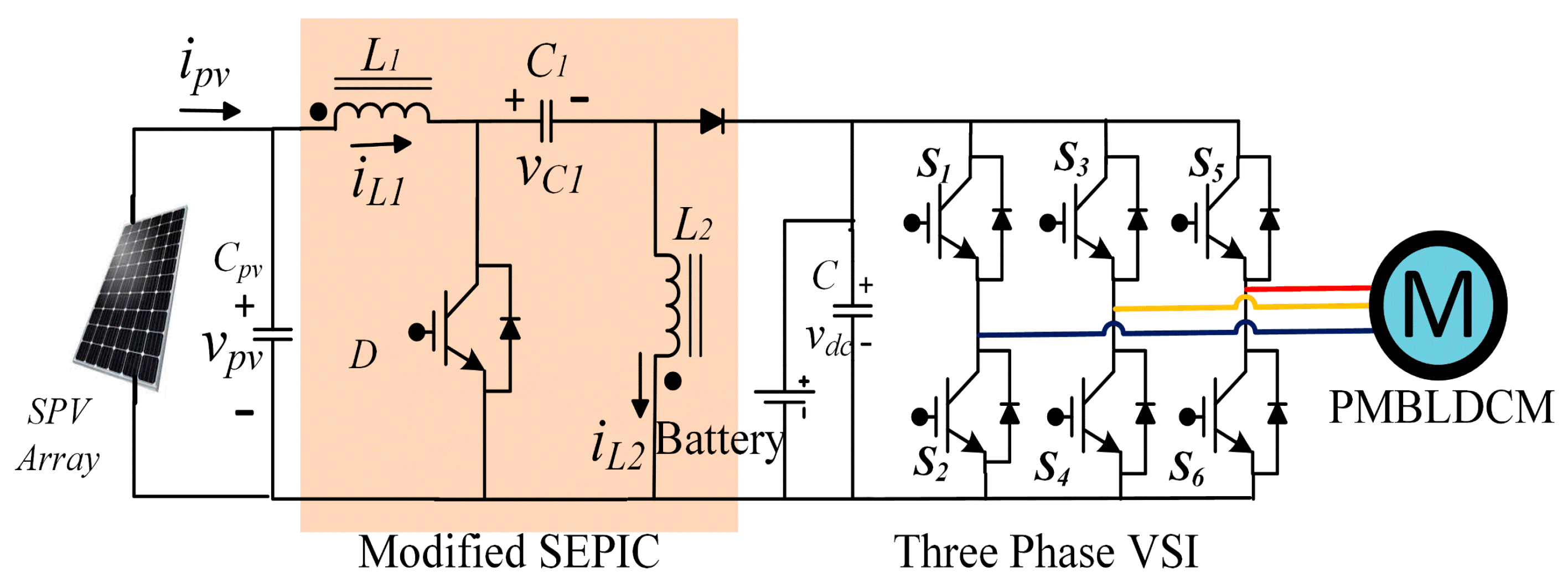
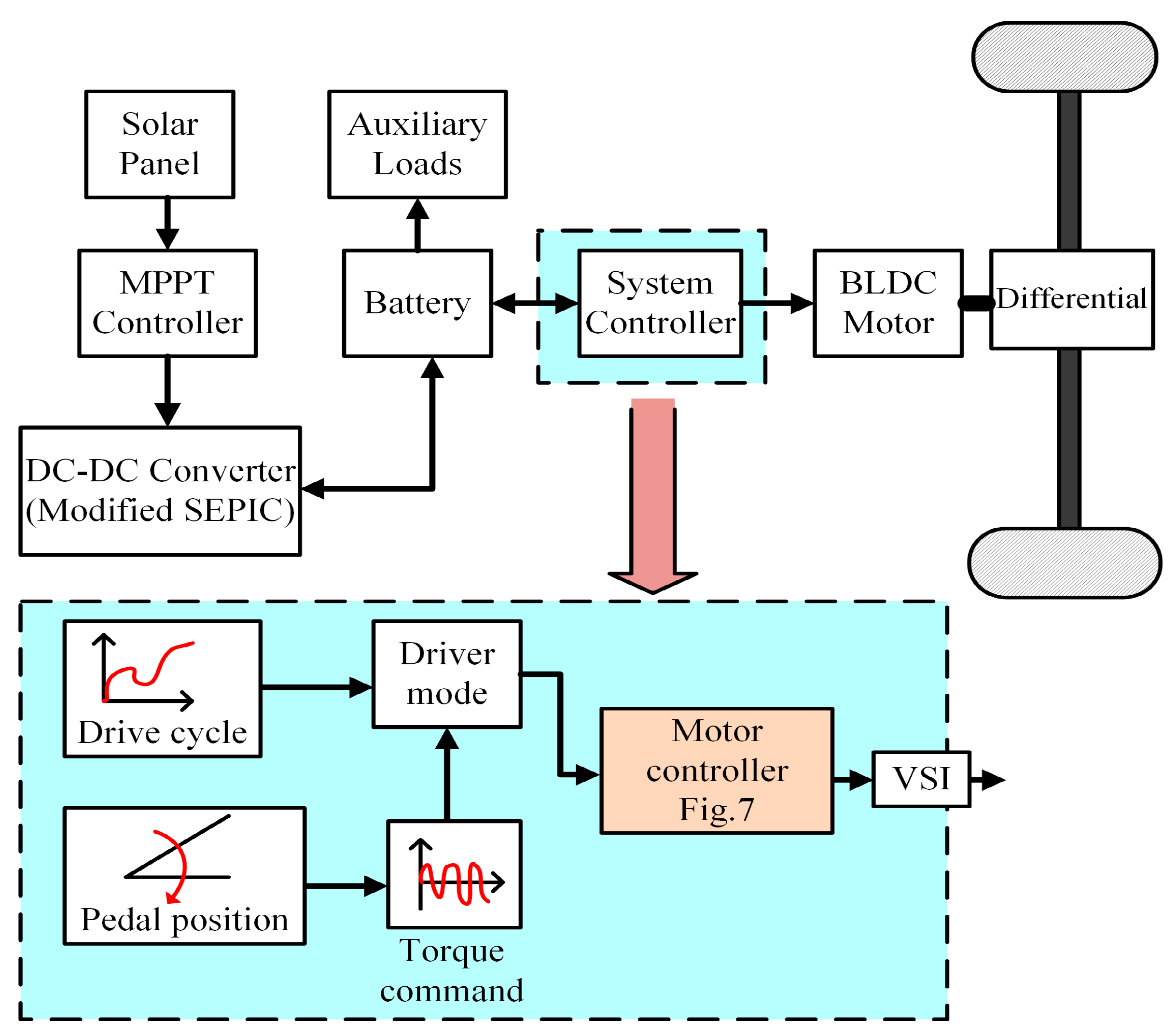
2. System Design and Configuration

The schematics of the proposed drive powertrain is illustrated in Figure 1. In the proposed drive system, the motor drivetrain is powered by a solar PV panel, which serves as the primary energy source. To ensure MPPT control, a SEPIC is employed. The motor drive is supplied through a battery connected to the DC link and a VSI. The control stage of the system integrates an encoderless BLDC motor drive with speed estimation and energy regeneration capabilities. The combination of the solar panel and battery ensures an uninterrupted power supply, even under adverse conditions. Gate pulses for the VSI are generated by combining the speed controller’s output with the commutation pulses from the sensorless control, as shown in Figure 2. The system operates with a 420 W solar PV array and a 48 V lithium-ion battery set. A 4-pole 0.85 kW permanent magnet BLDCM with a peak power rating of 1.25 kW is selected for the drive.

2.1. Rating and Specifications of the Solar Panel

The solar panel is rated at Ppv = 420 W peak, with each module comprising 60 series-connected cells. This configuration results in an open-circuit voltage (Voc) of 72 V and a rated short-circuit current (isc) of 7.84 A. The maximum power point voltage (Vmp) is determined to be 29 V, which corresponds to 40% of Voc. Similarly, the rated current (imp) at maximum power is observed to be 7.34 A, representing 93% of isc. To ensure that the maximum voltage at the optimal power point (Vmpp) remains 58 V, the required number of modules (Ns) in series is calculated at Ns = 2 as follows:
N s = V m p p V m p
The root mean square (rms) current at the maximum power point (MPP) is calculated at impp = 7.24 A given by Equation (2). Therefore, following Equation (3), one module in parallel is sufficient to achieve the rated impp:
i m p p = P p v V m p p
N p = i m p p i m p
Using Equations (1)–(3), the design of the solar PV array is formulated by employing a perturb and observe (P&O) MPPT algorithm.

2.2. Design and Control of the SEPIC

The SEPIC is a versatile DC-DC converter that can step up, step down, or maintain the input voltage level depending on the operating conditions. The converter efficiently handles a broad range of input voltages, making it ideal for MPPT in PV systems.
The design of the SEPIC is carried out considering operation in continuous conduction mode (CCM). As depicted in Figure 1, to achieve a non-inverted SEPIC configuration, the positions of the output inductor and the diode in the Cuk converter are reversed. With the non-inverted output, the output voltage maintains the same polarity as the input, simplifying integration with downstream components. The design also includes inductors on both the input and output sides, which minimize current ripple and ensure smooth power delivery. The design of passive components for the converter are described in the following. The design of these components is carried out based on the optimal power point.
The duty cycle (D) for Vdc = 48 V and Vmpp = 58 V is determined at D = 0.45 following Equation (4). The input inductor current is iL1 = impp = 7.24 A. The current through the DC bus, idc, is defined as per Equation (5) considering the peak power capability Pdc = 1.25 kW, achieving idc = 26.04 A.
D = V d c V d c + V m p p
i d c = P d c V d c
In the proposed design, the ripple current is shared equally between the two inductors, effectively halving the required inductance (L1 = L2). The inductors are sized according to Equation (6), calculated at L1 = L2 = 0.90 mH, ensuring CCM while minimizing current ripple. For optimal cost and size, the switching frequency fsw is set to 20 kHz, with a maximum current ripple of 10% (ΔiL1 = 0.1 · iL1).
L 1 = L 2 = 1 2 · D ·   V m p p f s w · Δ i L 1
The flying or coupling capacitor C1 facilitates energy transfer and protects against short-circuits in the load. The capacitor reduces the voltage ripple. Its value is estimated at C1 = 97.64 μF following Equation (7), where VC1 = Vdc = 48 V and the maximum allowed voltage ripple is set at 10% (ΔVC1 = 0.1 · VC1). A ceramic capacitor with a low equivalent series resistance (ESR) value is preferred for this application.
C 1 = D ·   i d c f s w · Δ V C 1
Finally, the diode prevents reverse current flow, and a metal–oxide–semiconductor field-effect transistor (MOSFET) is used as the switching device controlled by a PWM signal, as developed hereafter.
The SEPIC operates by regulating the duty cycle D of its switching element to control the input voltage (Vpv) seen by the PV panel. The input voltage of the SEPIC directly determines the operating point of the PV panel. The relationship between Vpv and the duty cycle is given by Equation (8):
V p v = V d c · 1 D D
By adjusting D, the converter changes Vpv, which shifts the operating point of the PV panel along its voltage–current characteristics. The MPPT controller determines the optimal D to achieve Vmpp, thus achieving maximum solar power extraction, i.e., the MPPT algorithm monitors Vpv and ipv to calculate the extracted power, and consequently adjusts D to move the operating point of the PV panel toward the maximum power point. The duty cycle is incremented and decremented iteratively to achieve maximum power. The optimal operating point is reached when the derivative of power with respect to voltage is zero, and the duty cycle is then stabilized. If Vpv < Vdc, the converter works on step-up operation (higher D), while if Vpv > Vdc, the converter works on step-down operation (lower D).
Beyond maximum power extraction, the SEPIC’s control strategy also ensures a stable output despite variations in solar irradiance, as well as variations in the PV panel’s temperature-dependent characteristics. The dynamic adjustment is achieved through a closed-loop feedback control system, involving a proportional-integral (PI) controller. The output voltage (Vdc) is continuously monitored and compared to a reference voltage, and the error is fed into a PI controller to generate a control signal. The PI controller adjusts the duty cycle D of the switch to bring Vdc closer to the reference voltage.

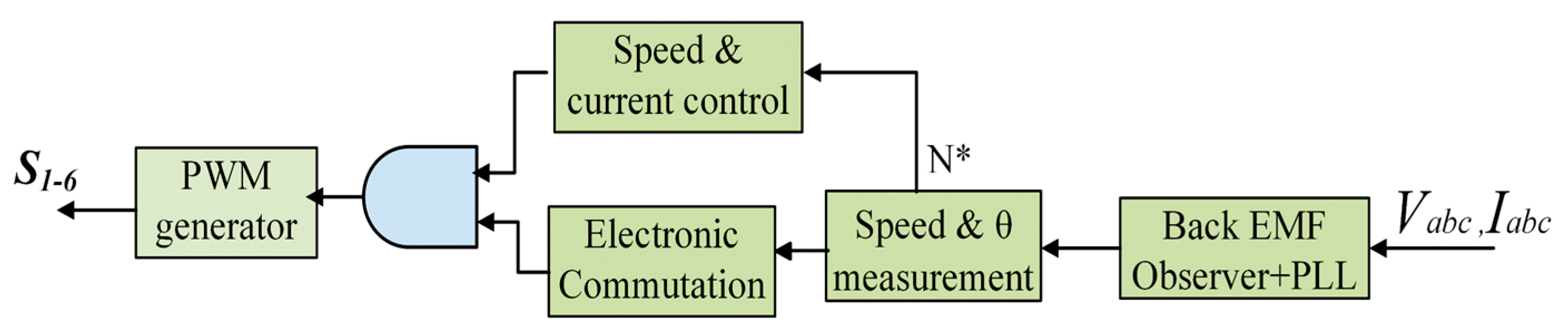
3. Control System Architecture

The overall control architecture of the BLDCM drive is divided into three main sections, which are described in the following.

3.1. Control of the Solar PV Array

To monitor the maximum power point in a solar PV array, the P&O technique is used. The duty ratio corresponding to the power output is adjusted in response to disturbances introduced into the system. The control mechanism continuously monitors and compares the PV array’s power output to its preceding value. If the power increases with an increment in perturbation, the perturbation is increased further. Conversely, if the power decreases, the previous perturbation value is restored. This iterative procedure determines the optimal duty ratio for the SEPIC, ensuring the solar PV array operates at its maximum power point.
While a smaller step size slows the tracking process, it improves accuracy and facilitates a smoother motor startup. However, the P&O technique has the drawback of exhibiting oscillations near the optimally stable operating region. To address this issue, the perturbation size is restricted to a maximum of 0.05 p.u. In this way, the tracking process is fast enough, and the amplitude of these oscillations is effectively reduced.

3.2. Sensorless Control with Conventional Back-EMF Observer

The trapezoidal back-EMF waveform of BLDCM serves as a reliable indicator for determining commutation instants. In this context, the line back-EMF is estimated using a nonlinear observer, as illustrated in Figure 3.
Considering phases A and B, along with their respective phase resistance R and inductance L, the BLDCM can be modeled following Equation (9), as a function of the phase currents (ia and ib), voltages (va and vb), and back-EMFs (ea and eb). In Equation (9), only the back-EMF, eab = eaeb, is unknown, while all other variables are known.
d d t i a i b = R L i a i b + 1 L v a v b 1 L e a e b
Using state-space observer modeling, the back-EMF êab is estimated according to Equations (10) and (11), where I and Î are the corresponding actual and estimated currents, respectively, and K1 and K2 are constants. Other line back-EMFs are estimated similarly using these equations.
  I ^ ˙ = R L ·   I ^ + 1 L · v a 1 L · e ^ a b + K 1 · ( I I ^ )
e ^ a b ˙ = K 2 · ( I I ^ )
The gains of the back-EMF observer, K1 and K2, are tuned using the pole-placement method [25]. It is important to note that higher values of observer gains tend to stabilize the observer; however, excessively high gains can amplify noise and cause chattering. Therefore, careful tuning is required to achieve an optimal balance in observer gain selection [17].
Commutation instants are determined by directly measuring the zero-crossing points of the line back-EMF of the BLDCM, which is the most conventional method for sensorless commutation. However, this approach suffers from significant lag at low speeds, leading to erroneous commutation. To address this issue, the estimated rotor position is further corrected as follows:
θ ^ = k k + 1 ω ^ e d t + θ 0
where the estimated rotor position θ ^ is updated at every (k + 1)th instant, through the estimated electrical speed ω ^ e , while the initial rotor position is θ 0 . The rotor position is determined using Equation (12) rather than relying solely on basic back-EMF zero-crossing points. The estimated electrical speed ω ^ e of the motor is defined as in Equation (13). The motor speed is primarily calculated using the estimated back-EMF, êab, and the machine constant K.
ω ^ e = e ^ a b K
Finally, the virtual Hall position signals (Ha*, Hb*, Hc*) are generated based on the rotor position estimations in Equation (12), in accordance with the following logic:
θ ^ 60 °   θ ^ 120 ° = H a *
θ ^ 60 °   θ ^ 120 ° = H b *
θ ^ 180 °   θ ^ 0 ° = H c *

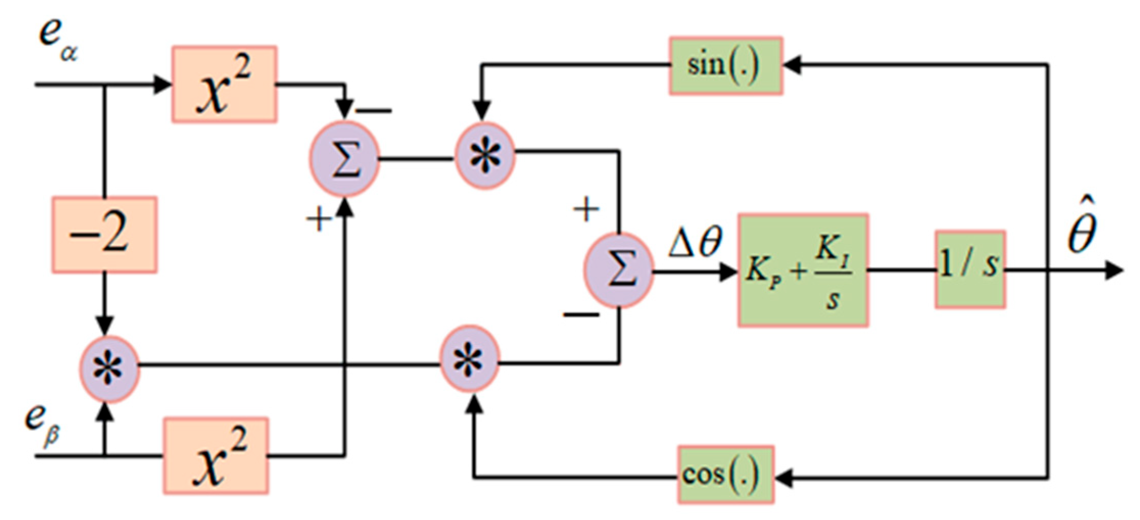
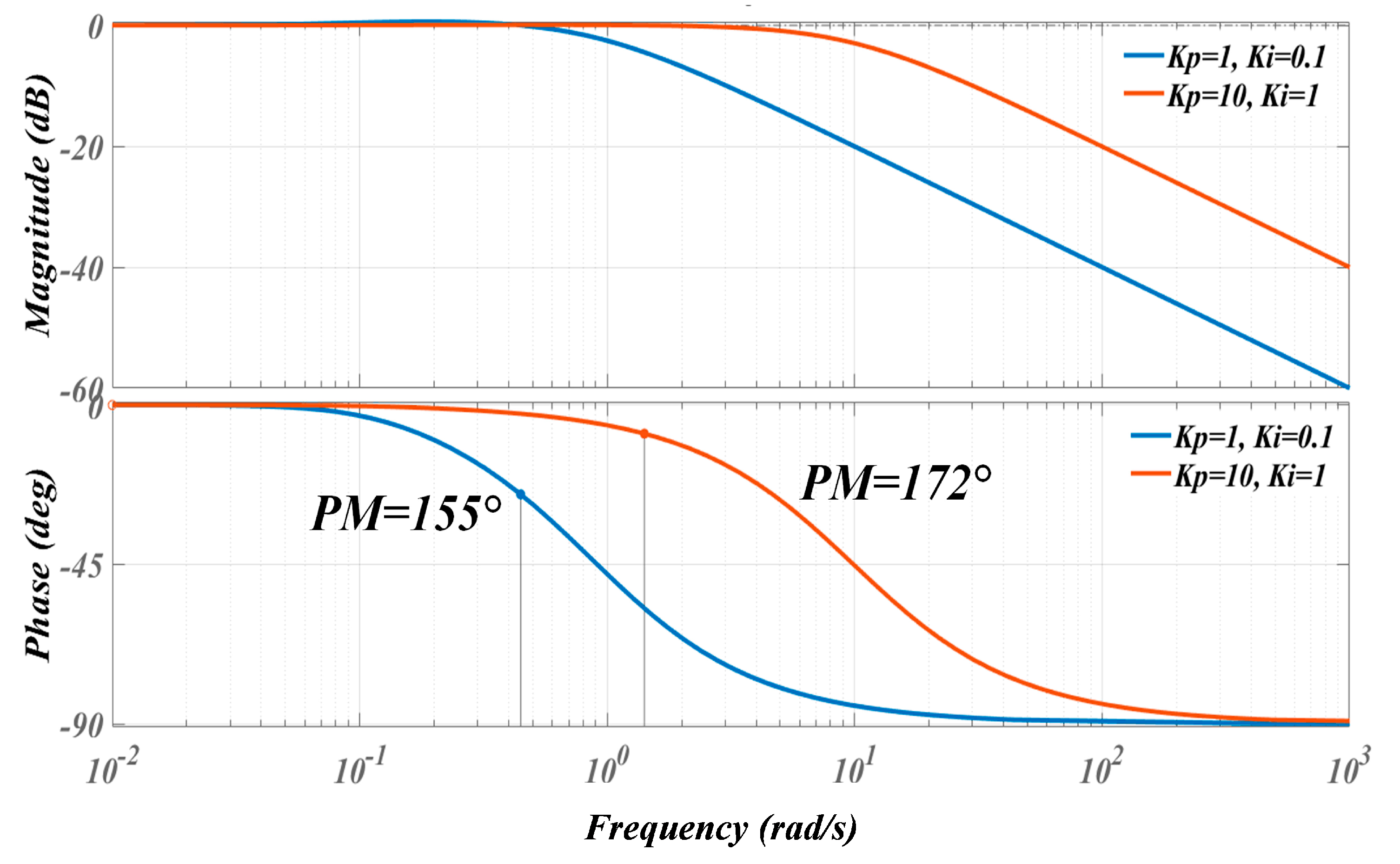
3.3. Modified Observer with Improved QPLL

Position estimation accuracy using direct back-EMF and the arc-tangent method can be affected by noise and harmonics, particularly at zero-crossing points. Therefore, an improved back-EMF is built, as shown in Figure 4. The QPLL structure is designed to accurately estimate rotor position and speed by leveraging the relationship between the back-EMF and rotor position. Its effectiveness lies in synchronizing its internally generated phase with the phase of the back-EMF to extract the rotor’s angular position with high precision.
The quadrature components of the back-EMF in the stationary αβ frame are computed using three sensed back-EMF signals, ea, eb and ec for phases ‘a’, ‘b’ and c’, respectively, through the general Clarke transform, according to Equation (17):
e α e β = 2 3 ·   1 1 2 1 2 0 3 2 3 2 ·   e a e b e c  
These orthogonal components can also be expressed as per Equation (18). The magnitude of the back-EMF is designated by E, and the actual rotor angular position is identified by θ .
e α e β = E ·   c o s θ s i n θ  
The QPLL generates an estimate of the back-EMF αβ components from the estimated rotor position θ ^ . These components can be expressed based on the same space construction, as per Equation (19):
e ^ α e ^ β = E ·   c o s θ ^ s i n θ ^
The objective of the QPLL is to minimize the phase difference between the actual rotor position ( θ ) and the estimated rotor position ( θ ^ ), denoted by   Δ θ , which is achieved by aligning the estimated and actual back-EMF components in the stationary αβ frame. The phase difference is captured by an error function ε(t). To effectively extract ε(t), the QPLL employs a signal transformation leveraging the trigonometric relationship expressed by Equation (20):
s i n θ ^ θ = s i n Δ θ = s i n θ ^ · c o s θ c o s θ ^ · s i n θ
The QPLL uses this information to calculate an error signal that drives the feedback loop. For small phase errors, s i n Δ θ   Δ θ , and additionally using the space transformation described by Equation (18) and scaling the error quadratically to avoid dependence on E, the final error function is achieved as follows:
Δ θ   ε t = e α 2 e β 2 · s i n θ ^ 2 · e α · e β · c o s θ ^  
The error function ε(t) measures the misalignment between the estimated and actual back-EMF components in the αβ frame. The first term emphasizes imbalances between the orthogonal components relative to the estimated phase, while the second term corrects for coupling effects and ensures synchronization. Assuming small error signals (ε(t) ≈ 0), Equation (22) provides a tangent estimation. The estimated position does not include speed information remaining accurate for any speed without delays.
t a n θ ^   2 · e α · e β e α 2 e β 2
The QPLL uses a PI controller to drive ε(t) to zero, ensuring synchronization between the estimated and actual rotor positions. The PI controller processes ε(t) to adjust the estimated rotor speed ω ^ and the rotor angular position θ ^ according to Equations (23) and (24), respectively.
ω ^ = K P + K I s · ε t
θ ^ = 1 s · ω ^
The dynamics of the QPLL can be modeled as a second-order system. Combining the PI control law with the error signal dynamics gives the transfer function shown in Equation (25).
θ ^ θ = K P · s + K I s 2 + K P · s + K I  
From Equation (25), it is deduced that increasing the proportional gain Kp enhances the system’s ability to quickly respond to changes in the back-EMF phase but may increase sensitivity to noise and high-frequency disturbances. On the other hand, increasing the integral gain KI helps eliminate residual phase error over time, ensuring precise rotor position estimation in the steady state. The ratio Kp/KI affects the damping of the QPLL system. A well-balanced ratio ensures minimal oscillations and fast convergence to the actual rotor position. There exists a trade-off between the dynamic performance of the QPLL and its disturbance rejection capability, which depends on the values of KP and KI.
It is worth noting that the speed-dependent variable loop gain exhibits different dynamic responses at varying speeds. To achieve a consistent dynamic response, in the proposed method, the magnitude of the fundamental components is kept constant across different speeds using a magnitude normalization method. For this, the αβ components of the back-EMF are divided by the peak flux magnitude to generate normalized back-EMF components, which are then fed to the QPLL. This approach mitigates higher-order harmonics, reduces noise propagation, and enables smooth and continuous speed estimation.
Using Equations (14)–(16), virtual Hall signals are estimated once the position information is available. The proposed QPLL enhances sensorless control by making it adaptive, eliminating delays in estimated positions. The Bode plot of the closed-loop QPLL, shown in Figure 5, demonstrates that the system is stable in the closed loop. Furthermore, Figure 6 illustrates that the rotor position is accurately tracked relative to the actual position signals.
It should be noted that the proposed estimator is based on the αβ components of the back-EMF, which stem from direct processing of the back-EMF signals through the QPLL. Thereby, the proposed method avoids reliance on speed-related information for position estimation, which allows for ensuring accurate and delay-free rotor position detection even at low speeds. This is the actual origin of the superiority of the proposed method compared to other back-EMF-based sensorless control methods. Due to this, the performance of the proposed method closely matches that of sensor-based control. However, in the case of fast dynamic conditions or large system disturbances, the constraints associated with the use of the QPLL would lead the proposed method to underperform sensor-based control.

3.4. Speed Controller

To ensure the motor consistently operates as a synchronous motor, virtual Hall position signals (Habc) are used to synchronize the stator currents (Iabc) with the back-EMFs. This approach maximizes torque output while minimizing ripple by maintaining constant currents during the intervals when the back-EMFs are also constant. Since back-EMFs exhibit a trapezoidal shape with a flat region of 120°, a six-step inverter operation is employed, where only two phases are active at any given time.
The speed controller, as illustrated in Figure 7, compares the motor speed (N*) to the speed reference (N) to generate the required additional torque (T*). Three current references are then generated (I*abc) and supplied to a hysteresis control system with an adjustable band to produce gating signals. The hysteresis control system generates gating signals for the three-phase inverter, with a variable switching frequency determined by the hysteresis band value and the dynamics of the stator circuit. By restructuring the stator currents using virtual Hall pulses and maintaining an optimized current profile, significant reductions in current ripple are achieved. Consequently, the torque profile is also improved, resulting in enhanced motor performance.

3.5. Regenerative Braking Control

Figure 8 illustrates the switching pattern employed for regenerative braking, where all switches are driven using pulse-width modulation (PWM). In each interval (I to VI), two of the six switches (S1 to S6) are activated for a duration of 60°. During the PWM-on state, the motor phase currents are reversed, enabling the rapid initiation of the braking process. Conversely, during the PWM-off state, the anti-parallel diodes allow the current to freewheel, thereby charging the battery. The modulation index governs the level of regeneration, with a higher modulation index permitting greater reverse current flow. As a result, the battery charges more rapidly, allowing for the recovery of a larger amount of energy using this technique.

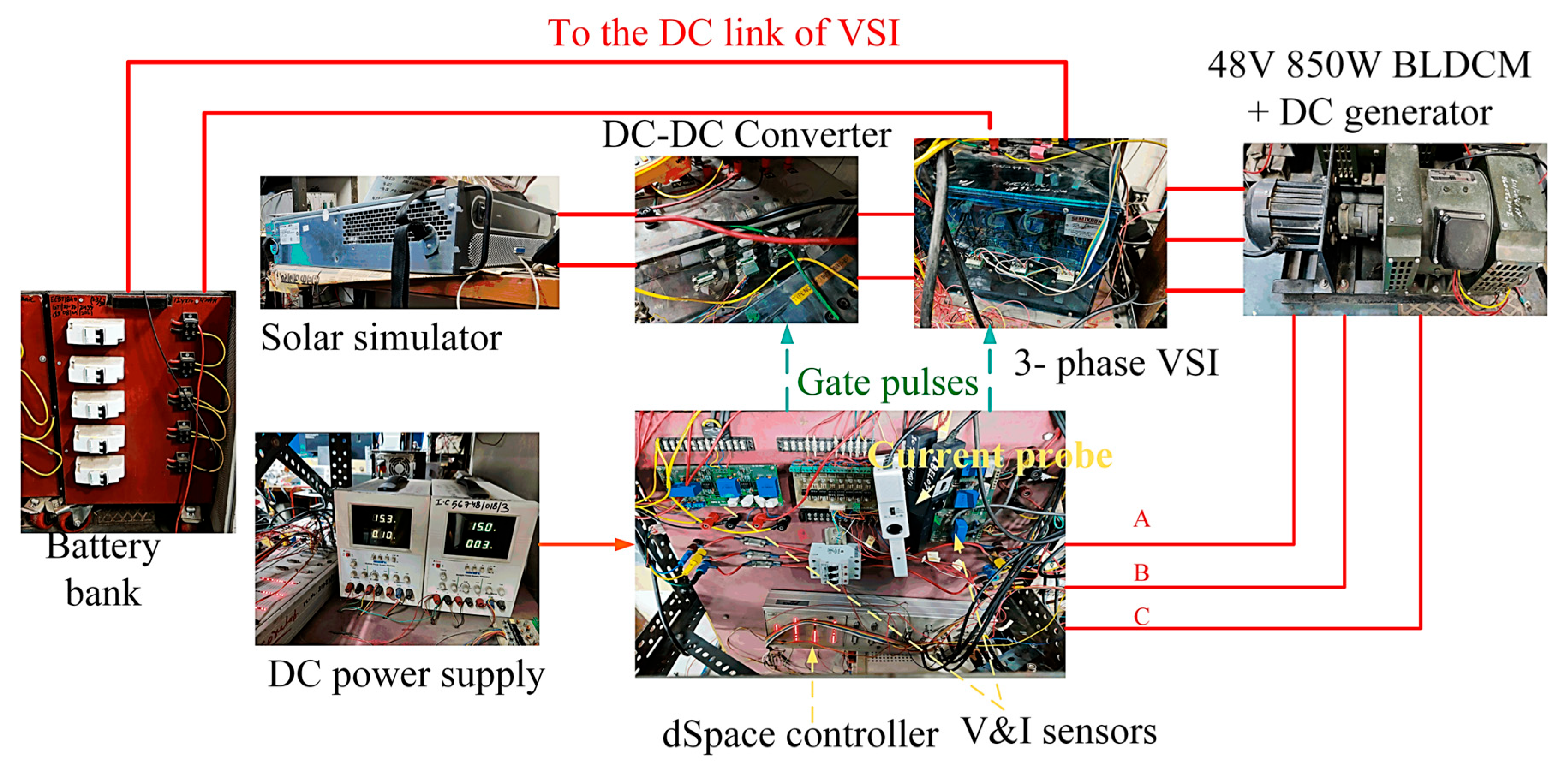
4. Experimental Testbench

MATLAB/Simulink and the experimental platform are used to develop and implement, respectively, a laboratory prototype of the system, shown in Figure 9. For experimental validation, a 48 V, 850 W BLDCM, single-speed and with 7:1 gear arrangement, commonly used in three-wheelers, is employed. The specifications of the BLDCM are provided in Table 2. The motor is capable of producing up to 1.25 kW of power at its peak.
The experimental setup comprises a PV emulator (solar simulator) to replicate the characteristics of a solar panel under varying irradiance conditions, providing a variable DC input to the SEPIC used as the DC/DC converter. The maximum solar power delivery is 420 W. The SEPIC is configured for MPPT and regulates the voltage supplied to the system. The switching frequency of the converter is 20 kHz. A 48 V, 100 Ah, lithium-ion battery pack serves as the energy storage unit, interfaced with the converter to support motoring and regenerative braking operations. The BLDCM is driven by a three-phase 10 kW VSI, controlled by a microcontroller (dSpace controller) that implements the sensorless QPLL-based back-EMF observer for rotor position estimation. Additional sensors are integrated to monitor phase currents, back-EMF voltages, and system performance metrics such as speed and torque. The feedback signals are acquired via analog–digital converters (ADCs) at a sampling rate of 20 kHz. The controller generates the final switch pulses for the VSI while processing inputs from voltage and current sensors, as well as the PWM signals for the SEPIC.
A DC machine coupled to the BLDCM acts as a vehicle load emulator. Standard drive cycles of a light three-wheel EV vehicle, based on the characteristics of Table 3, are used as reference speed commands for load control. Figure 10 illustrates a simplified architecture of the overall vehicle control system. The system controller encompasses the primary drive structure, serving as the central component of the system. To replicate vehicle dynamics, both the drive cycle and the accelerator pedal are used as inputs to the controller. The drive cycle is employed to validate controller performance by comparing it to a preset reference speed command. Alternatively, the accelerator pedal provides an additional input method. The degree of pedal pressure determines the estimated reference torque command, which is then transmitted to the “driver mode” block. This block selects either the drive cycle or the accelerator mode as the input command to the motor controller block.
The tests were conducted under a variety of operating scenarios to evaluate the system’s performance. Motor operating conditions included a wide speed range, with particular focus on the lower range (from 100 to 1000 rpm). Steady-state operation tests were performed with constant speed, as well as dynamic tests with varying speed. Load torque was varied by controlling the DC generator, emulating the typical operating conditions of a light EV. The PV emulator was configured for varying irradiance levels, from lower (250 W/m2) to higher (1000 W/m2) values, in order to replicate real solar conditions. Steady-state tests were performed with constant irradiance level, as well as dynamic tests with abrupt variations. Additionally, temperature effects on the PV panel were emulated by altering the open-circuit voltage and short-circuit characteristics of the emulator. Regenerative braking was tested under both light braking conditions, characterized by low reverse currents, and aggressive braking scenarios, where higher negative torque resulted in reverse currents reaching up to 10 A.
The data collection process used precise instrumentation to capture the system’s performance metrics. An oscilloscope was used to record the signals, including back-EMF waveforms, phase currents, and inverter PWM patterns. A data logger continuously monitored and recorded the PV emulator’s output voltage, current, and power. Torque and speed sensors measured the motor’s mechanical output parameters. To compare the position estimation accuracy of the QPLL-based sensorless algorithm with other methods, the estimated rotor positions were compared against measurements obtained from Hall-effect sensors temporarily installed for validation purposes. The regenerative braking efficiency was calculated as the ratio of energy recovered to the battery and the kinetic energy dissipated during braking. To ensure reliability, all tests were repeated three times under identical conditions.

5. Results and Analysis

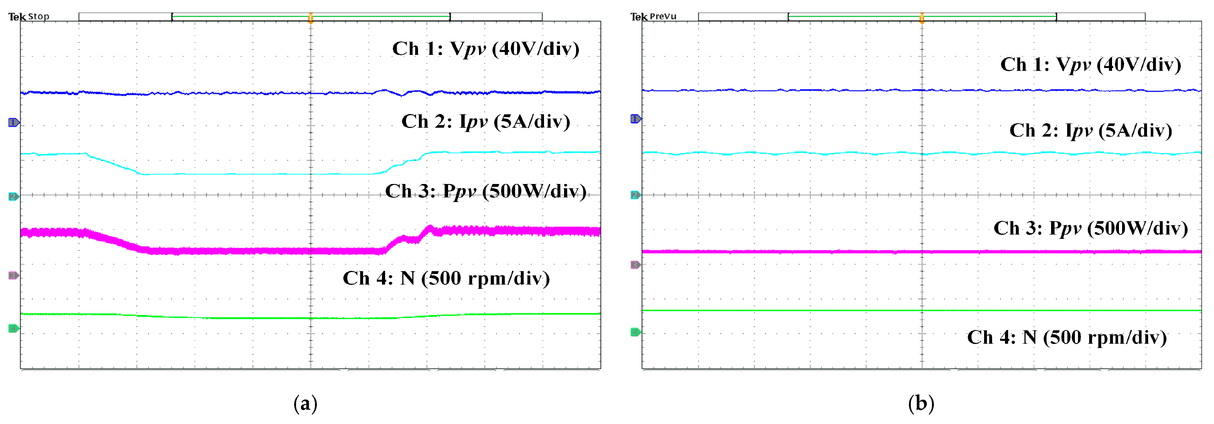
5.1. Performance of the Solar PV Array and Converter

The efficiency of the PV array, defined as the ratio of electrical output power to incident solar power, was found to average 19.2% under standard test conditions, demonstrating effective energy conversion. The response time of the MPPT algorithm, measuring the system’s ability to adapt to rapid changes in irradiance, averaged 170 ms during step changes from 1000 W/m2 to 500 W/m2, ensuring minimal power loss during environmental fluctuations.
Figure 11a demonstrates the successful performance of the P&O MPPT algorithm in a solar PV array utilizing a SEPIC, under fluctuating solar insolation conditions. The insolation varies with a step change from 1000 W/m2 to 500 W/m2, and the MPPT algorithm effectively tracks the maximum power point. As shown in Figure 11b, under maximum steady insolation, the optimal power (Ppv) of 420 W, as designed, is achieved, indicating satisfactory operation of the system.
The performance indices of the solar PV array, including currents (iPV), output voltage (VPV), power (Ppv), and motor speed (N), are shown in Figure 11a,b. The inductor current ripples are maintained within the range of 5%, below the specified design limits, ensuring smooth current and voltage at the output. An additional advantage of this converter is its non-inverting output voltage. Moreover, the motor speed remains unaffected by variations in solar insolation.
In Figure 11a,b it is observed that stability is maintained across the varying conditions, with the MPPT algorithm showing minimal oscillations around the maximum power point due to an optimized step size in the P&O method. Experimental MPPT performance is shown in Figure 12a,b. The system exhibited strong robustness, maintaining power extraction efficiency above 95% of the theoretical maximum power point during partial shading and wide irradiance variations, facilitated by the SEPIC’s capability to handle significant input voltage fluctuations.

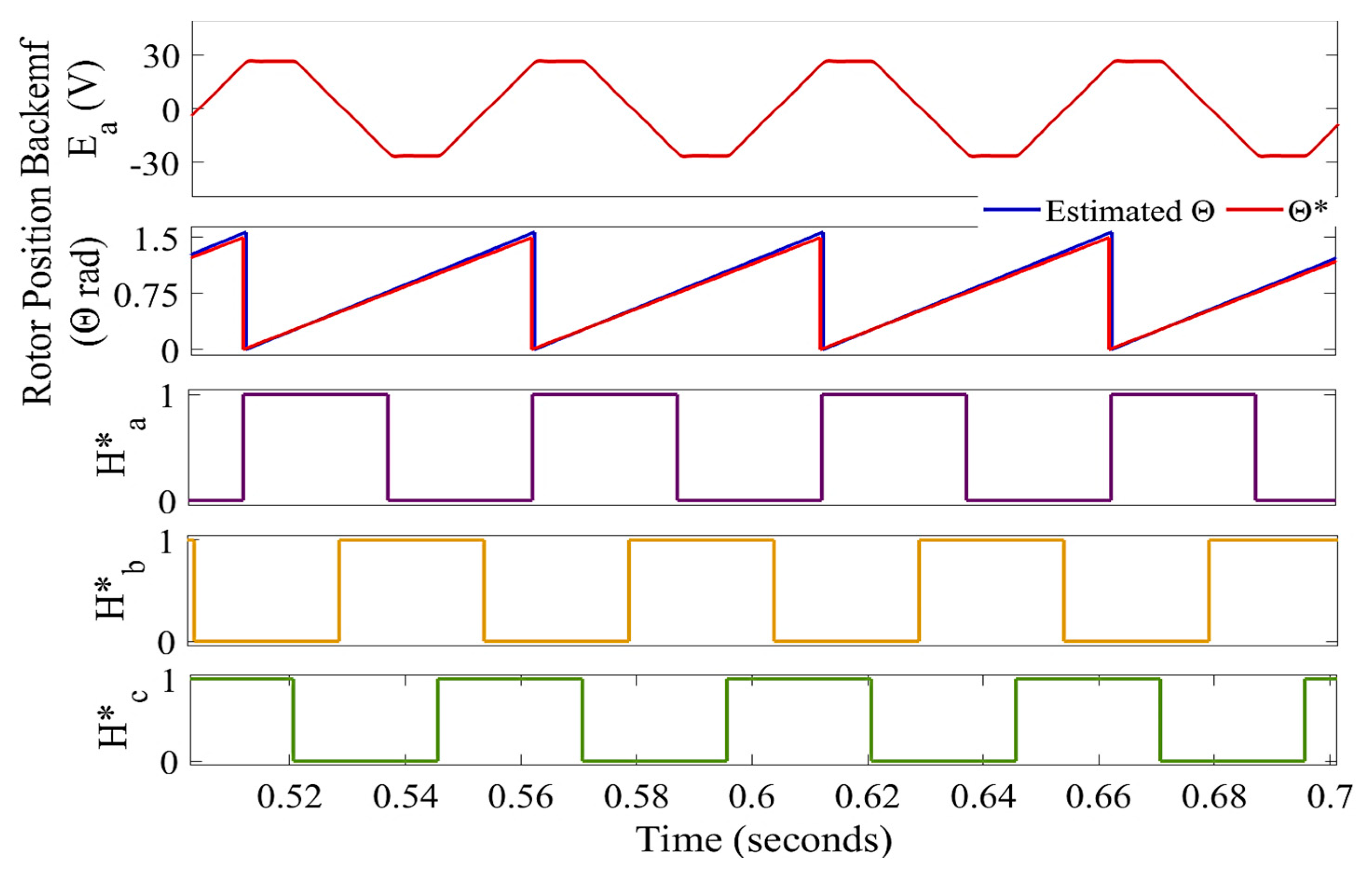
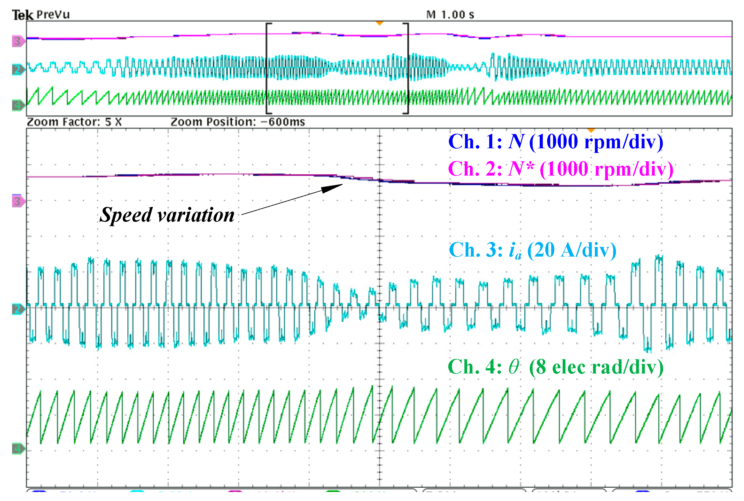
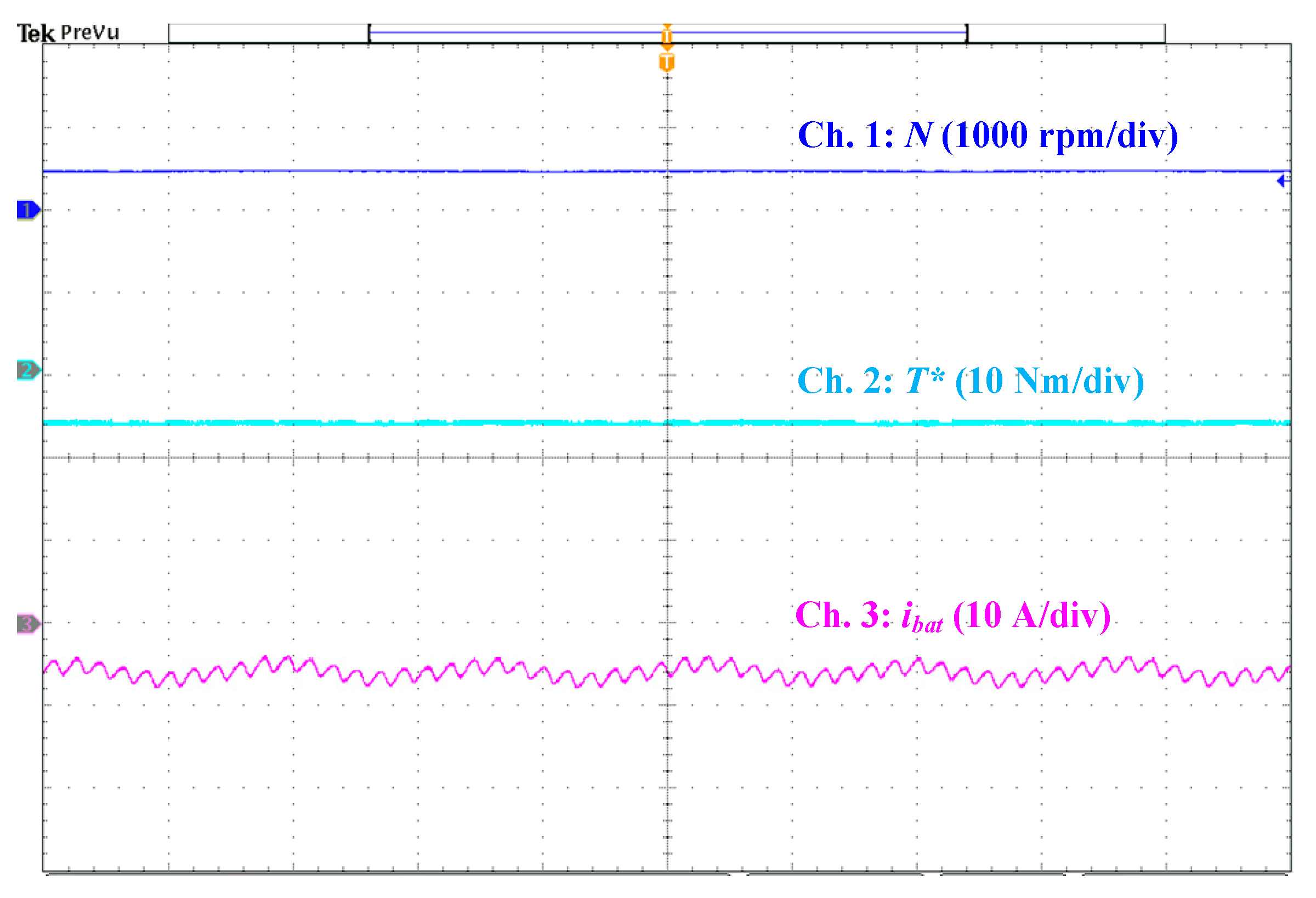
5.2. Performance of the Sensorless BLDCM Drive Control

Figure 13, Figure 14 and Figure 15 show the steady-state performance of the BLDCM drive across three different speed ranges: low (100 rpm), medium (500 rpm), and high (above 1000 rpm). It is evident from these figures that the sensorless operation of the drive works effectively across a wide speed range without any delay. The rotor position (θ), terminal voltage of the motor (Vab), stator phase current (ia), and speed (N) are illustrated in these figures. Smooth motor currents are obtained, free of oscillations and ripple. The estimated rotor position shows a satisfactory correlation with the actual rotor position. Using the obtained position information, the estimated Hall pulses (H*a, H*b, H*c) can be derived. These virtual Hall signals play a crucial role in determining the switching sequences of the VSI.
The spikes in line voltages in Figure 13, Figure 14 and Figure 15 are caused by inductive voltage build-up due to the sudden change in current in the motor windings, which are inductive in nature. The implemented QPLL, with its inherent filtering capability, filters out all high-order harmonics caused by distorted voltage and current waveforms. The estimated angular positions remain unperturbed throughout all speed ranges.
Figure 16 depicts both the starting performance and the steady-state behavior of the drive. Figure 17 illustrates the estimated Hall pulses (Ha*) and the reference current signal (ia*) for phase “a” at 400 rpm. The reference current is fed to the current controller to generate the gate pulses. The filtered back-EMF from the observer in the αβ domain (Eα) is also shown in Figure 17.
The dynamic performance of the sensorless algorithm-based BLDCM drive, incorporating speed control, is shown in Figure 18. This figure illustrates the actual and reference speeds (N* and N), motor current for phase “a” (ia) and rotor angular position (θ). The motor is tracking a reference speed of 800 rpm, and the speed then dips to 200 rpm. The system operates with a 10 Nm load torque. The actual stator current is shown with minimal ripple, controlled by the current controller. The rotor position remains constant throughout the operation, ensuring that the drive is stable during speed dynamics across a wide speed range.
Figure 19 demonstrates the regenerative braking performance. As seen in this figure, the drive is in regenerative braking mode. Due to the incorporated regenerative braking control, the battery is charged during braking. Negative battery current (ibat < 0) and torque (T* < 0) confirm that the drive is in regenerative mode. Drive performance is recorded at 500 rpm and a 5 Nm load torque. With a torque of 5 Nm, the battery charges with an average current of 7 A, while the peak current is recorded as 10 A. As the load torque increases, the charging current rises, leading to a higher amount of regenerative energy being recovered.
The evaluation of the regenerative braking motor efficiency, based on the system’s ability to recover part of the motor’s kinetic energy spent during braking and store that energy in the battery [42], led to a peak efficiency of 30.60%. This result overperforms state-of-the-art efficiencies in similar BLDC motor applications, limited to 6.9% and 15.8% for single- and two-boost open-loop regeneration methods, respectively [8]: 19.45% (two-boost, closed-loop regeneration method [43]), and 23.44% (improved two-boost, closed-loop regeneration method [44]).
Finally, Figure 20a,b present a comparative graphical analysis of the sensorless methods, focusing on the error in position estimation obtained through experimental testing. The commutation error achieved by the proposed back-EMF observer with improved QPLL is compared with the conventional back-EMF observer and the zero-crossing point (ZCP) detection-based method [42]. They were also tested under analogous experimental conditions.
Based on the experimentally obtained position error tracking in Figure 20a,b, it is evident that the implemented back-EMF QPLL observer-based position estimation outperforms conventional approaches. The position error is finely brought to near-zero in steady-state conditions by integrating the improved QPLL with the back-EMF observer. Even during transients, such as changes in speed, the position error remains minimal with the implemented back-EMF QPLL observer-based sensorless control, compared to the other mentioned methods.
The experimental results demonstrate the efficacy of the QPLL-based back-EMF observer in achieving accurate rotor position estimation across a wide speed range. Its low-speed performance, where traditional methods typically struggle as developed in Section 1, should be emphasized. At low speeds (e.g., below 300 rpm), the QPLL effectively mitigates the challenge of low back-EMF amplitude by dynamically adjusting its loop gain, ensuring stable and precise position estimation without introducing excessive noise or delay. This is evident from the near-zero commutation error observed during both steady-state and transient conditions. At higher speeds, the proposed method maintains consistent performance, with negligible deviation in the estimated position and speed, highlighting its robustness. Furthermore, the system exhibits rapid dynamic response to sudden changes in speed, as evidenced by the minimal transient duration and overshoot in experimental waveforms. The findings underscore the superior dynamic adaptability of the QPLL-based observer, making it a practical solution for sensorless control in solar-powered BLDCM drives.

6. Conclusions

This study presented an enhanced encoderless brushless DC motor drive for solar PV array and battery-fed EVs, utilizing a back-EMF observer integrated with a QPLL technique for accurate position estimation. The sensorless algorithm effectively starts the motor at low speeds and performs reliably under varied operating conditions.
The design supports both solar PV battery charging and regenerative braking. The use of a non-inverted SEPIC ensures steady MPPT performance and makes the system well suited for solar-PV-based EV applications. By replacing the conventional arc-tangent method with QPLL, the design achieves superior low-speed performance with reduced noise and enhanced accuracy. The updated back-EMF observer, coupled with the robust QPLL, ensures precise position and speed estimation over a wide speed range.
Eliminating the need for low-pass filters and leveraging QPLL’s advanced filtering capabilities improves system adaptability and minimizes delays. The position sensorless drive, combined with regenerative braking, alleviates range anxiety and establishes a reliable and efficient EV powertrain suitable for solar- and battery-powered vehicles.
On the downside, the QPLL introduces a trade-off between dynamic response and filtering accuracy. Moreover, large disturbances in the DC bus voltage can also affect the QPLL by destabilizing the loop and introducing errors in position estimation. Finally, the high computational complexity necessitates the use of advanced, thus costly, controllers. Addressing these drawbacks opens avenues for future work, related to adaptive QPLL gain scheduling to improve responsiveness while maintaining stability, integration of advanced disturbance rejection techniques to ensure robustness, and optimization of the algorithm for hardware implementation. Furthermore, detailed regenerative braking efficiency analysis should be conducted, as a prelude for energy recovery optimization algorithms based on speed, load, and battery state of charge.
Finally, while the experimental results presented in this study effectively demonstrate the steady-state and dynamic performance of the proposed method, future work shall incorporate more diverse dynamic scenarios, such as responses under varying load disturbances and rapid accelerations and decelerations, to further test the robustness and applicability of the system.

Author Contributions

Conceptualization, B.S. (Biswajit Saha) and B.S. (Bhim Singh); methodology, B.S. (Biswajit Saha), A.S. and B.S. (Bhim Singh); software, B.S. (Biswajit Saha), A.S. and B.S. (Bhim Singh); validation, K.M. and J.A.S.-F.; formal analysis, K.M. and J.A.S.-F.; investigation, B.S. (Biswajit Saha), A.S. and K.M.; resources, B.S. (Bhim Singh) and J.A.S.-F.; data curation, B.S. (Biswajit Saha); writing—original draft preparation, B.S. (Biswajit Saha) and A.S.; writing—review and editing, B.S. (Bhim Singh), K.M. and J.A.S.-F.; visualization, B.S. (Biswajit Saha) and K.M.; supervision, B.S. (Bhim Singh) and K.M.; project administration, B.S. (Bhim Singh), K.M. and J.A.S.-F.; funding acquisition, K.M. and J.A.S.-F. All authors have read and agreed to the published version of the manuscript.

Funding

This research was funded by Universidad Politécnica de Madrid, grant number RP2304330031.

Institutional Review Board Statement

Not applicable.

Informed Consent Statement

Not applicable.

Data Availability Statement

The original contributions presented in the study are included in the article, further inquiries can be directed to the corresponding author.

Conflicts of Interest

The authors declare no conflicts of interest.

References

  1. Vaidehi, S.D.; Jayakumar, A.; Lavanya, R.; Kumar, M.D. Techno-Economic Assessment of Various Motors for Three-Wheeler E-Auto Rickshaw: From Indian Context. Mater. Today Proc. 2021, 45, 6572–6579. [Google Scholar] [CrossRef]
  2. Prabhu, N.; Thirumalaivasan, R.; Ashok, B. Critical Review on Torque Ripple Sources and Mitigation Control Strategies of BLDC Motors in Electric Vehicle Applications. IEEE Access 2023, 11, 115699–115739. [Google Scholar] [CrossRef]
  3. Akrami, M.; Jamshidpour, E.; Frick, V. Application of Hall Position Sensor in Control and Position Estimation of PMSM—A Review. In Proceedings of the 2023 IEEE International Conference on Environment and Electrical Engineering and 2023 IEEE Industrial and Commercial Power Systems Europe (EEEIC/I&CPS Europe), Madrid, Spain, 6–9 June 2023; pp. 1–6. [Google Scholar]
  4. Akrami, M.; Jamshidpour, E.; Nahid-Mobarakeh, B.; Pierfederici, S.; Frick, V. Sensorless Control Methods for BLDC Motor Drives: A Review. IEEE Trans. Transp. Electrif. 2025; Early Access. [Google Scholar] [CrossRef]
  5. Mohammad, K.; Rashid, M.F.; Rahat, H.; Khan, F.; Rahman, K. Detailed Analysis of DC-DC Converters Fed with Solar-PV System with MPPT. In Proceedings of the 2022 International Conference for Advancement in Technology (ICONAT), Goa, India, 21–23 January 2022; pp. 1–6. [Google Scholar]
  6. Sutikno, T.; Samosir, A.S.; Aprilianto, R.A.; Purnama, H.S.; Arsadiando, W.; Padmanaban, S. Advanced DC–DC Converter Topologies for Solar Energy Harvesting Applications: A Review. Clean Energy 2023, 7, 555–570. [Google Scholar] [CrossRef]
  7. Saha, B.; Singh, B. Back-EMF Observer Based Sensorless BLDC Motor Drive with SEPIC Converter for EV Application. In Proceedings of the 2021 IEEE 6th International Conference on Computing, Communication and Automation (ICCCA), Arad, Romania, 17–19 December 2021; pp. 94–99. [Google Scholar]
  8. Bahrami, M.; Mokhtari, H.; Dindar, A. Energy Regeneration Technique for Electric Vehicles Driven by a Brushless DC Motor. IET Power Electron. 2019, 12, 3397–3402. [Google Scholar] [CrossRef]
  9. Nian, X.; Peng, F.; Zhang, H. Regenerative Braking System of Electric Vehicle Driven by Brushless DC Motor. IEEE Trans. Ind. Electron. 2014, 61, 5798–5808. [Google Scholar] [CrossRef]
  10. Ahmad, F.; Pandey, M.; Zaid, M. Sensorless Control of Brushless DC Motor by Zero-Crossing Detection Pulse Generation with Adaptive Power Factor Control Technique. In Proceedings of the 2018 IEEE International Conference on Environment and Electrical Engineering and 2018 IEEE Industrial and Commercial Power Systems Europe (EEEIC/I&CPS Europe), Palermo, Italy, 12–15 June 2018; pp. 1–6. [Google Scholar]
  11. Yang, L.; Zhu, Z.Q.; Bin, H.; Zhang, Z.; Gong, L. Virtual Third Harmonic Back-EMF-Based Sensorless Drive for High-Speed BLDC Motors Considering Machine Parameter Asymmetries. IEEE Trans. Ind. Appl. 2021, 57, 306–315. [Google Scholar] [CrossRef]
  12. Antonello, R.; Ortombina, L.; Tinazzi, F.; Zigliotto, M. Enhanced Low-Speed Operations for Sensorless Anisotropic PM Synchronous Motor Drives by a Modified Back-EMF Observer. IEEE Trans. Ind. Electron. 2018, 65, 3069–3076. [Google Scholar] [CrossRef]
  13. Zhang, H.; Deng, L.; Li, H.; Zheng, S.; Jin, H.; Chen, B. Commutation Point Optimization Method for Sensorless BLDC Motor Control Using Vector Phase Difference of Back-EMF and Current. IEEE/ASME Trans. Mechatron. 2024, 29, 423–433. [Google Scholar] [CrossRef]
  14. Filho, C.J.V.; Xiao, D.; Vieira, R.P.; Emadi, A. Observers for High-Speed Sensorless PMSM Drives: Design Methods, Tuning Challenges and Future Trends. IEEE Access 2021, 9, 56397–56415. [Google Scholar] [CrossRef]
  15. Nair, S.V.; Hatua, K.; Prasad, N.V.P.R.D.; Reddy, D.K. A Quick I-f Starting of PMSM Drive with Pole Slipping Prevention and Reduced Speed Oscillations. IEEE Trans. Ind. Electron. 2021, 68, 6650–6661. [Google Scholar] [CrossRef]
  16. Wang, T.; Huang, J.; Ye, M.; Chen, J.; Kong, W.; Kang, M.; Yu, M. An EMF Observer for PMSM Sensorless Drives Adaptive to Stator Resistance and Rotor Flux Linkage. IEEE J. Emerg. Sel. Top. Power Electron. 2019, 7, 1899–1913. [Google Scholar] [CrossRef]
  17. Yang, S.-C.; Chen, G.-R. High-Speed Position-Sensorless Drive of Permanent-Magnet Machine Using Discrete-Time EMF Estimation. IEEE Trans. Ind. Electron. 2017, 64, 4444–4453. [Google Scholar] [CrossRef]
  18. Ok, S.; Xu, Z.; Lee, D.-H. A Sensorless Speed Control of High-Speed BLDC Motor Using Variable Slope SMO. IEEE Trans. Ind. Appl. 2024, 60, 3221–3228. [Google Scholar] [CrossRef]
  19. Cai, J.; Gu, Y.; Cheok, A.D.; Yan, Y. A Survey of Phase-Locked Loop Technologies in Sensorless Position Estimation of Permanent Magnet Synchronous Motor Drives. IEEE Trans. Instrum. Meas. 2024, 73, 1504016. [Google Scholar] [CrossRef]
  20. Yin, Z.; Zhang, Y.; Cao, X.; Yuan, D.; Liu, J. Estimated Position Error Suppression Using Novel PLL for IPMSM Sensorless Drives Based on Full-Order SMO. IEEE Trans. Power Electron. 2022, 37, 4463–4474. [Google Scholar] [CrossRef]
  21. Li, J.; Sun, Y.; Lin, J.; Li, X.; Zhou, F.; Dan, H. Reduced-Order Adaptive Observer with Asymptotic Stability for Sensorless Control of SPMSM. IEEE Trans. Power Electron. 2025, 40, 588–598. [Google Scholar] [CrossRef]
  22. Wang, B.; Shao, Y.; Yu, Y.; Dong, Q.; Yun, Z.; Xu, D. High-Order Terminal Sliding-Mode Observer for Chattering Suppression and Finite-Time Convergence in Sensorless SPMSM Drives. IEEE Trans. Power Electron. 2021, 36, 11910–11920. [Google Scholar] [CrossRef]
  23. Woldegiorgis, A.T.; Ge, X.; Wang, H.; Hassan, M. A New Frequency Adaptive Second-Order Disturbance Observer for Sensorless Vector Control of Interior Permanent Magnet Synchronous Motor. IEEE Trans. Ind. Electron. 2021, 68, 11847–11857. [Google Scholar] [CrossRef]
  24. Masoudi, H.; Kiyoumarsi, A.; Madani, S.M.; Ataei, M. Torque Ripple Reduction of Nonsinusoidal Brushless DC Motor Based on Super-Twisting Sliding Mode Direct Power Control. IEEE Trans. Transp. Electrif. 2023, 9, 3769–3779. [Google Scholar] [CrossRef]
  25. Li, P.; Sun, W.; Shen, J.-X. Flux Observer Model for Sensorless Control of PM BLDC Motor with a Damper Cage. IEEE Trans. Ind. Appl. 2019, 55, 1272–1279. [Google Scholar] [CrossRef]
  26. Bendjedia, B.; Chouireb, S. Comparative Study Between Sensorless Vector Control of PMSM Drives Based on MRAS, SMO, and EKF Observers. In Proceedings of the 2023 International Conference on Advances in Electronics, Control and Communication Systems (ICAECCS), Blida, Algeria, 9–11 May 2023; pp. 1–6. [Google Scholar]
  27. Cao, R.; Jiang, N.; Lu, M. Sensorless Control of Linear Flux-Switching Permanent Magnet Motor Based on Extended Kalman Filter. IEEE Trans. Ind. Electron. 2020, 67, 5971–5979. [Google Scholar] [CrossRef]
  28. Chen, D.; Wang, J.; Zhou, L. Adaptive Second-Order Active-Flux Observer for Sensorless Control of PMSMs with MRAS-Based VSI Nonlinearity Compensation. IEEE J. Emerg. Sel. Top. Power Electron. 2023, 11, 3076–3086. [Google Scholar] [CrossRef]
  29. Bierhoff, M.H. A General PLL-Type Algorithm for Speed Sensorless Control of Electrical Drives. IEEE Trans. Ind. Electron. 2017, 64, 9253–9260. [Google Scholar] [CrossRef]
  30. Tong, L.; Zou, X.; Feng, S.; Chen, Y.; Kang, Y.; Huang, Q.; Huang, Y. An SRF-PLL-Based Sensorless Vector Control Using the Predictive Deadbeat Algorithm for the Direct-Driven Permanent Magnet Synchronous Generator. IEEE Trans. Power Electron. 2014, 29, 2837–2849. [Google Scholar] [CrossRef]
  31. Wu, X.; Li, J.; Chen, S.; Ma, Z.; Han, Y.; Zhang, X. Sensorless Control of Permanent Magnet Synchronous Motor Based on Double-Cost-Function Finite-Position-Set Phase-Locked Loop. IEEE Trans. Ind. Electron. 2025; Early Access. [Google Scholar] [CrossRef]
  32. Golestan, S.; Guerrero, J.M.; Vasquez, J.C. Three-Phase PLLs: A Review of Recent Advances. IEEE Trans. Power Electron. 2017, 32, 1894–1907. [Google Scholar] [CrossRef]
  33. Jiang, F.; Sun, S.; Liu, A.; Xu, Y.; Li, Z.; Liu, X. Robustness Improvement of Model-Based Sensorless SPMSM Drivers Based on an Adaptive Extended State Observer and an Enhanced Quadrature PLL. IEEE Trans. Power Electron. 2021, 36, 4802–4814. [Google Scholar] [CrossRef]
  34. Song, X.; Han, B.; Zheng, S.; Fang, J. High-Precision Sensorless Drive for High-Speed BLDC Motors Based on the Virtual Third Harmonic Back-EMF. IEEE Trans. Power Electron. 2018, 33, 1528–1540. [Google Scholar] [CrossRef]
  35. Zhang, H.; Liu, G.; Zhou, X.; Zheng, S. High-Precision Sensorless Optimal Commutation Deviation Correction Strategy of BLDC Motor with Asymmetric Back EMF. IEEE Trans. Ind. Inform. 2021, 17, 5250–5259. [Google Scholar] [CrossRef]
  36. Santra, S.B.; Chatterjee, A.; Chatterjee, D.; Padmanaban, S.; Bhattacharya, K. High Efficiency Operation of Brushless DC Motor Drive Using Optimized Harmonic Minimization Based Switching Technique. IEEE Trans. Ind. Appl. 2022, 58, 2122–2133. [Google Scholar] [CrossRef]
  37. Zuo, Y.; Lai, C.; Iyer, L.V. Improved Single Current Sensor Based PMSM Control under Low Frequency Ratio Using Discrete-Time Adaptive Luenberger Observer. IEEE Trans. Ind. Electron. 2024, 71, 10297–10308. [Google Scholar] [CrossRef]
  38. Nguyen, T.H.; Nguyen, T.T.; Le, K.M.; Tran, H.N.; Jeon, J.W. An Adaptive Backstepping Sliding-Mode Control for Improving Position Tracking of a Permanent-Magnet Synchronous Motor with a Nonlinear Disturbance Observer. IEEE Access 2023, 11, 19173–19185. [Google Scholar] [CrossRef]
  39. Sun, L. Low Speed Sensorless Control Method of Brushless DC Motor Based on Pulse High Frequency Voltage Injection. Alex. Eng. J. 2022, 61, 6457–6463. [Google Scholar] [CrossRef]
  40. Kwon, Y.-C.; Lee, J.; Sul, S.-K. Recent Advances in Sensorless Drive of Interior Permanent-Magnet Motor Based on Pulsating Signal Injection. IEEE J. Emerg. Sel. Top. Power Electron. 2021, 9, 6577–6588. [Google Scholar] [CrossRef]
  41. Sun, X.; Cai, F.; Yang, Z.; Tian, X. Finite Position Control of Interior Permanent Magnet Synchronous Motors at Low Speed. IEEE Trans. Power Electron. 2022, 37, 7729–7738. [Google Scholar] [CrossRef]
  42. Saha, B.; Singh, B.; Sen, A. Solar PV Integration to E-Rickshaw with Regenerative Braking and Sensorless Control. IEEE Trans. Ind. Appl. 2022, 58, 7680–7691. [Google Scholar] [CrossRef]
  43. Basu, A.; Singh, M. An Efficient Energy Recovery Approach of a BLDC Driven E-Rickshaw in Regenerating Braking Mode. Sci. Iran. 2024. [Google Scholar] [CrossRef]
  44. Basu, A.; Singh, M.; Vardhan, A.S.S. Energy Regeneration of a Position Sensorless BLDC-Driven PV E-Rickshaw with Regenerative Braking. Electr. Eng. 2024, 106, 1357–1372. [Google Scholar] [CrossRef]
Figure 1. Schematics of the proposed drive powertrain.
Applsci 15 00574 g001
Figure 2. Mechanism for the switching pulses to the VSI.
Applsci 15 00574 g002
Figure 3. Back-EMF observer block diagram.
Applsci 15 00574 g003
Figure 4. Modified back-EMF observer with improved QPLL.
Applsci 15 00574 g004
Figure 5. Bode plot of the improved QPLL.
Applsci 15 00574 g005
Figure 6. Observer output virtual Hall pulses with rotor position.
Applsci 15 00574 g006
Figure 7. Observer virtual Hall output pulses.
Applsci 15 00574 g007
Figure 8. Switching pulses to the VSI during regenerative braking.
Applsci 15 00574 g008
Figure 9. Experimental laboratory prototype.
Applsci 15 00574 g009
Figure 10. Comprehensive drive train structure of BLDCM-driven light EV.
Applsci 15 00574 g010
Figure 11. Performance of the solar PV array [(a) Dynamic performance, with solar insolation from 1000 W/m2 to 500 W/m2; (b) Steady-state performance for 1000 W/m2]. Time per division: 10 ms.
Applsci 15 00574 g011
Figure 12. Experimental MPPT performance [(a) 1000 W/m2 irradiance; (b) 500 W/m2 irradiance].
Applsci 15 00574 g012
Figure 13. Steady-state performance of the BLDCM drive at 100 rpm. Time per division: 10 ms.
Applsci 15 00574 g013
Figure 14. Steady-state performance of the BLDCM drive at 500 rpm. Time per division: 4 ms.
Applsci 15 00574 g014
Figure 15. Steady-state performance of the BLDCM drive at 1000 rpm. Time per division: 4 ms.
Applsci 15 00574 g015
Figure 16. Dynamic performance of the BLDCM drive: motor starting. Time per division: 2 s.
Applsci 15 00574 g016
Figure 17. Dynamic performance of the BLDCM drive: observer performance during sensorless control. Time per division: 10 ms.
Applsci 15 00574 g017
Figure 18. Dynamic performance of the BLDCM drive: sensorless position estimation with speed control. Time per division: 200 ms.
Applsci 15 00574 g018
Figure 19. Energy regeneration of the BLDCM drive. Time per division: 10 ms.
Applsci 15 00574 g019
Figure 20. Comparative performance analysis: (a) Commutation errors with different methods under steady-state conditions; (b) commutation errors with different methods during speed change dynamics.
Applsci 15 00574 g020
Table 1. Comparative analysis of sensorless BLDCM control methods.
Sensorless TechnologyMeritsDemerits
Back-EMF zero-crossing
  • Only 2 voltage sensors required
  • Less computational burden
  • Direct position estimation using comparator
  • Position estimation is not accurate at low speed
  • LPF introduces phase lag
  • Compensator is required
  • Delay is not fully compensated
Third harmonic back-EMF variation
  • Neutral point voltage fluctuation is avoided
  • Similarly to conventional back-EMF zero-crossing
  • High filtering requirement
  • Estimated position pulses are twice the actual frequency of Hall pulses
  • Lag-lead compensation required for delay compensation
Conventional back-EMF observer
  • Easy computation compared to other nonlinear observers
  • Observer modeling is further made easier in the stator reference frame
  • Fast dynamic response under full-load variation
  • Suitable for medium- to high-speed range
  • LPF is required which introduces delay
  • Obtaining theta using arc-tangent method adds unwanted noise
Sliding mode observer (SMO)
  • Both speed and position estimation are possible
  • Continuous position information is obtained
  • Complex computation
  • Chattering problem
  • Additional filtering requirement
  • Low-speed performance affected due to high-order harmonics
Super-twisting SMO (STO)
  • Reduces chattering compared to conventional SMO
  • Maintains robust tracking
  • Suitable for noisy environments
  • Complex gain design
  • Computationally intensive
Flux-based observer
  • Torque can also be estimated along with speed and position
  • Suitable for wide speed range application
  • Minimum position error due to adaptive control
  • Complex computation
  • Estimated flux has offset problem due to integration operation at low speed
  • Magnitude attenuation due to lowpass filter
Extended Kalman Filter (EKF)
  • Near optimal estimation
  • Robust to noise
  • Adaptive feedback gain adjustment
  • Effective under varying loads
  • High computational cost
  • Complex tuning of covariance matrices
  • Sensitive to parameter variations
Luenberger observer
  • Simple linear feedback mechanism
  • Applicable in both stationary and synchronous frames
  • Robust gain tuning available
  • Requires accurate parameter knowledge
  • Less effective at handling high-frequency disturbances
Linear disturbance observer (LDO)
  • Simplifies design
  • Computationally efficient
  • Suitable for moderate noise levels
  • Ineffective for high-frequency disturbances
  • Requires tuning for sudden load changes
Frequency-adaptive observers (SOGI, MSOGI, DSOGI)
  • Isolates fundamental components effectively
  • Excellent harmonic suppression
  • Adapts to varying frequencies
  • Computationally demanding
  • Sensitive to parameter mismatches
Multiple harmonic elimination (MHE) observers
  • Eliminate low-order harmonics dynamically
  • Improve robustness against distortions
  • Effective for high-speed operation
  • High computational complexity
  • Stability analysis poses challenges
Machine parameter-adaptive observers (RLS, MRAS, adaptive PI)
  • Dynamically adjusts resistance, inductance, and flux
  • Robust under varying conditions
  • Improves reliability across ranges
  • Convergence issues among estimators
  • High computational burden
Saliency-based observers
  • Effective at low speeds
  • Leverage rotor anisotropy for position estimation
  • Robust to back-EMF limitations
  • Requires high-frequency signal injection
  • Causes torque ripple and mechanical noise
Proposed QPLL-based back-EMF observer
  • Precise position estimation
  • Improved low speed performance
  • LPF is avoided
  • Speed-adaptive position estimation suitable for all operating speeds
  • Avoids noise associated with the arc-tangent method
  • The addition of QPLL affects the dynamics response
  • Disturbances, such as in DC bus voltage, can affect the QPLL performance
  • High computation complexity
Table 2. BLDCM specifications.
ParameterValueUnits
Rated power850W
Peak power1250W
Rated voltage48V
Rated current21A
Peak current50A
Rated speed3000rpm
Stator per-phase resistance0.18Ω
Stator per-phase inductance50mH
Rated torque2.7Nm
Peak torque20Nm
Pole pairs2
Inertia0.02kg·m2
Table 3. Parameters of the emulated light EV.
Component or CharacteristicValue or Type
Propulsion typeElectrical, 850 W BLDCM
Drive modeTorque control
Maximum speed25 km/h
Wheel diameter304.80 mm
Vehicle dimensions2850 × 1050 × 1800 mm
Net weight190 kg
Peak loading capacity400 kg
Disclaimer/Publisher’s Note: The statements, opinions and data contained in all publications are solely those of the individual author(s) and contributor(s) and not of MDPI and/or the editor(s). MDPI and/or the editor(s) disclaim responsibility for any injury to people or property resulting from any ideas, methods, instructions or products referred to in the content.

