1. Introduction
A metasurface (MS) reflectarray antenna capable of focusing and steering the reflected beam is presented in this work. By adjusting the local phase distribution, one can synthesize the reflected beam radiation patterns ranging from flat mirror to flat-parabolic surfaces (FLAPS) and enable precise beam steering at an angle of θ [
1,
2,
3,
4,
5]. Placing a horn antenna at the focal point of the FLAFS produces a collimated beam, while a planar wave incident on the FLAPS focuses the reflected beam, demonstrating the designed phase-gradient properties [
5,
6].
Conventional phased arrays achieve beam steering through electronically controlled RF chains comprising components such as phase shifters, PIN diodes, varactors, and MEMS. At millimeter-wave frequencies, however, their performance is constrained by nonlinearities, limited power-handling capability, and substantial insertion losses, which increase as the number of elements in the phased array rises [
7,
8,
9,
10]. Tunable mechanisms using materials such as liquid crystals, ferroelectrics, and graphene offer alternative approaches; however, they are mostly limited to single-cell demonstrations due to their complexity, slow response times, and limited bandwidth [
11,
12,
13,
14].
Mechanical tuning is achieved by moving, rotating, or bending metasurface layers, which addresses the limitations mentioned above. Large-scale motions of the ground plane or patch-patterned board enable continuous phase shifts without discrete bias networks, providing low-loss performance and high-power handling capability [
15,
16,
17,
18,
19]. In particular, a mushroom-style high-impedance surface with a tunable capacitive patch array has demonstrated beam steering via in-plane rotation [
17], whereas flexure-based reflectarrays have exhibited tunability through out-of-plane displacement [
18,
19,
20].
This paper presents a full RF characterization of the proposed Reconfigurable Electro-Mechanical Reflectarray (REMR) for E-band communications [
21], which was initially studied only through simulations. The REMR uses two types of unit cells (Type-A/Type-B) to achieve a 350° phase dynamic tuning range with sub-dB insertion losses [
21]. Here, the design from [
21] is implemented and experimentally tested using a piezoelectric crystal bender that tilts the ground plane. The experimental results confirmed precise beam focusing and ±3° beam steering, showing excellent agreement with the simulations reported in [
21]. By tilting the ground plane instead of individually biasing each element, the REMR provides a compact, robust, low-cost, and power-efficient solution for E-band and millimeter-wave communication systems. Moreover, the piezoelectric actuation is intrinsically energy-efficient (capacitive load): it draws negligible static power and requires only brief charge/discharge pulses during updates, enabling fast, millisecond-scale beam trimming with very low power consumption and minimal thermal overhead.
Based on this study, an innovative unit cell configuration was developed. This innovative unit cell features a flat ground surface, which simplifies fabrication and reduces costs. Phase tunability is now achieved by a dual-patch configuration, which includes one patch on the front side and a second patch on the back of the unit cell. This configuration enables beam steering of ±6° and a phase dynamic range of almost 360° over the 78–82 GHz frequency range. This new configuration reduces the manufacturing cost of the REMR compared to the current tested configuration [
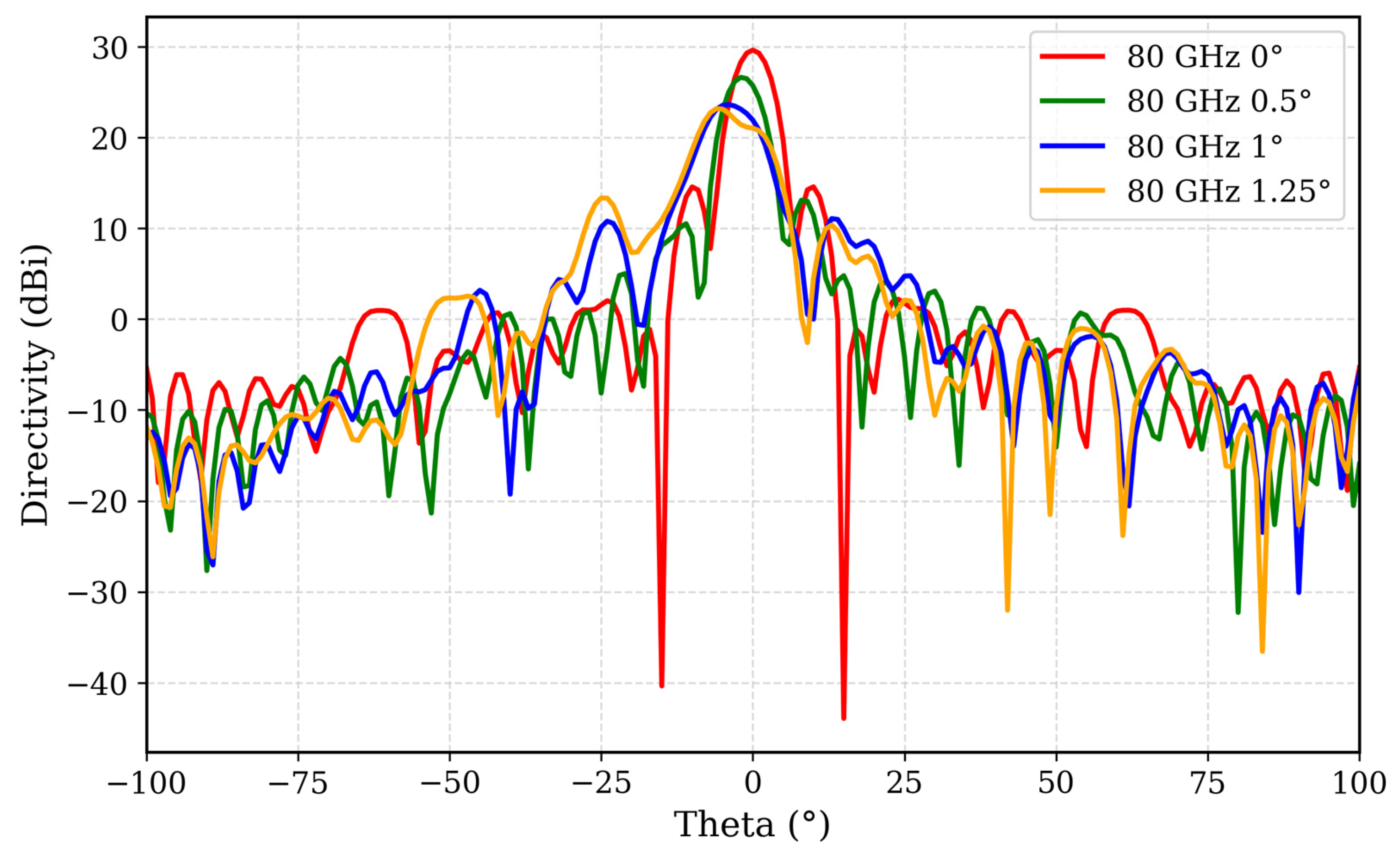
21]. In addition, the overall mechanical stack was intentionally designed for higher kinematic sensitivity: calibration shows that a 1.0° cam-rod rotation yields a 4° beam deflection, and 1.25° yields about 6°, enabling fine pointing control with modest mechanical stroke.
2. MS Design and REMR Construction
2.1. Unit-Cell Architecture and Phase-Dynamic Range
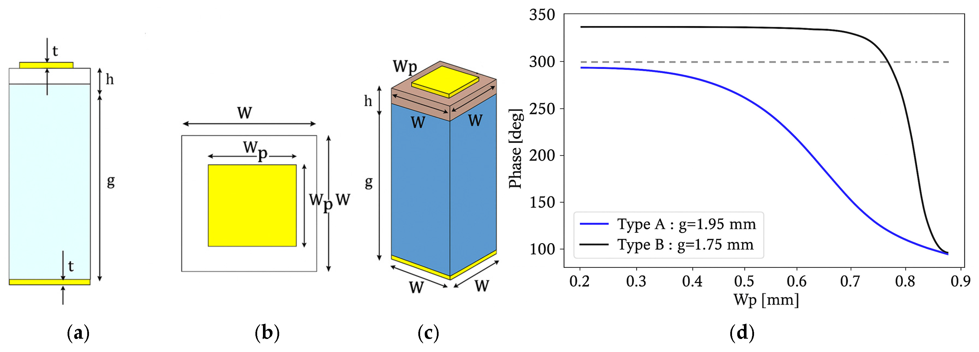
The E-band unit cell, shown in
Figure 1 [
21], relies on two geometric parameters, the patch width
and the air gap thickness g, to expand its dynamic phase range without compromising efficiency. Adjusting
tunes the resonant reflection phase of each cell, while varying the air gap thickness g between the patch layer and the ground layer provides an additional degree of freedom for continuous phase control.
The tested REMR employs two complementary square-patch unit cells, where type A has an air gap of g = 1.95 mm and type B has an air gap of g = 1.75 mm (see
Figure 1). The structure operates over a wide bandwidth of 78–82 GHz with low losses and a broad dynamic phase range [
21]. The exact dimensions of the unit cells are listed in
Table 1. By sweeping the patch width
, a wide range of reflected phases can be achieved. Arranging unit cell types A and B across the aperture yields a phase range exceeding 300° while keeping the losses extremely low, below 0.1 dB. A dashed gray line at 290° in
Figure 1 marks the transition between type A and type B unit cells. This dual unit cell configuration not only extends the dynamic phase range but also ensures a smooth, monotonic phase progression as a function of
.
The circular-aperture REMR presented in [
21] employed the Type A and Type B unit cells discussed above, with a diameter D = 80 mm and a focal length F = 80 mm at the millimeter-wave frequency of f = 80 GHz. Computer code was used to generate the MS with the specified unit-cell configuration. Each unit cell, either Type A or Type B, was assigned a patch width
according to the required local phase to satisfy the design specifications.
2.2. Equivalent-Circuit Model
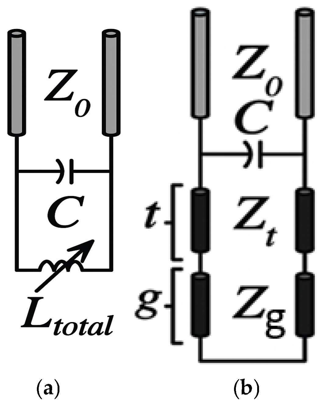
Each unit cell of the designed MS, as described above, behaves as a parallel-LC circuit, with the corresponding lumped component model presented in
Figure 2a that was derived from
Figure 2b where Zt is the input impedance of the short-circuited dielectric-substrate transmission-line stub, and Zg is the input impedance of the short-circuited air-gap (ground) stub.
The capacitance C of the unit cell is approximated as [
22,
23]:
where
is the cell size,
is the gap spacing between two adjacent patches,
is the effective permittivity, and
is the free space impedance.
The total inductance, which accounts for the effects of both the dielectric layer (thickness
, permittivity
) and the air gap g, is given by:
Thus, the resonance frequency is given by:
At resonance, the surface behaves as a (near) perfect magnetic conductor (PMC), exhibiting a reflection coefficient close to 1 with a reflection phase of approximately 0°, whereas a perfect electric conductor (PEC) produces a reflection phase of ±180°.
2.3. Construction of the REMR
A unique computer code was used to design the MS and determine the local reflected phase for each unit cell, automatically selecting either type A or type B to achieve the desired phase. The code was provided with the REMR diameter D = 80 mm, focal length F = 80 mm, and frequency f = 80 GHz as input parameters. The designed REMR was subsequently simulated, validated, and fabricated based on the code output, and its performance was assessed in the laboratory.
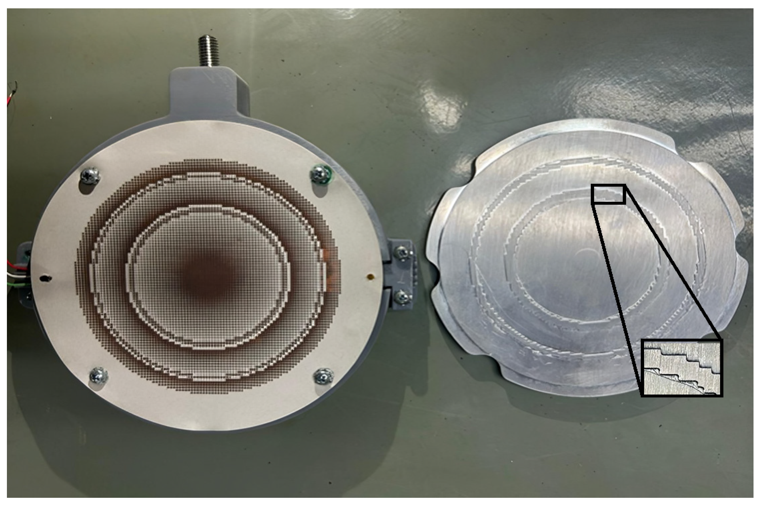
Figure 3 shows a photo of the manufactured REMR, which consists of two parts: front and back. The front side (
Figure 3, Left) features the patch layer on the PCB, arranged according to the computer code design. The back side (
Figure 3, Right) includes a metal ground plate with two steps, which indicate the type (A or B) of each unit cell. A piezoelectric crystal bend was positioned between the patch layer and the ground plate to rotate the plate and steer the reflected beam, as illustrated in
Figure 4.
As shown in
Figure 3, right, the metal ground plate has milled contours that follow the arrangement of Type-A and Type-B unit cells. The manufacturing accuracy of the two-step ground plate was 10 µm. Rogers 5880 was used as the substrate for the front-side PCB (
Figure 3, Left), which supports copper patches whose widths were determined by the design parameters and the computer code output.
Mechanical tuning stability. Ground-plane rotation is actuated by a piezoelectric bimorph (Thorlabs PB4VB2W) in differential drive. To mitigate the intrinsic hysteresis of the piezo, all voltage setpoints during measurement were approached from the same polarity, constraining motion to a single hysteresis branch. This choice is slightly less efficient than bidirectional sweeping but yields more repeatable beam pointing over the acquisition window. In future work, we will implement a simple error-correction loop (e.g., lookup-table linearization or closed-loop feedback) to compensate the residual nonlinearity.
Two piezoelectric bender actuators (Thorlabs PB4NB2W, Newton, NJ, USA) were mounted beneath the ground plate and driven by a control system. When biased, each bender flexes about its midpoint, producing a small rotation angle
, as illustrated in
Figure 4. This creates an approximately linear air-gap profile Δg between the ground plate and the patch layer. The piezoelectric actuators provide a displacement of ±450 µm, enabling a continuous phase gradient across the REMR and allowing ±3° steering of the reflected beam.
As the local gap changes by , the equivalent inductance Ltotal varies smoothly across the aperture, shifting each cell’s resonant phase. This unique configuration simplifies the hardware required to control the reflection phase of each unit cell, enabling sub-microsecond response times and sub-dB losses.
3. Experimental Setup and Results
3.1. Experimental Set-Up
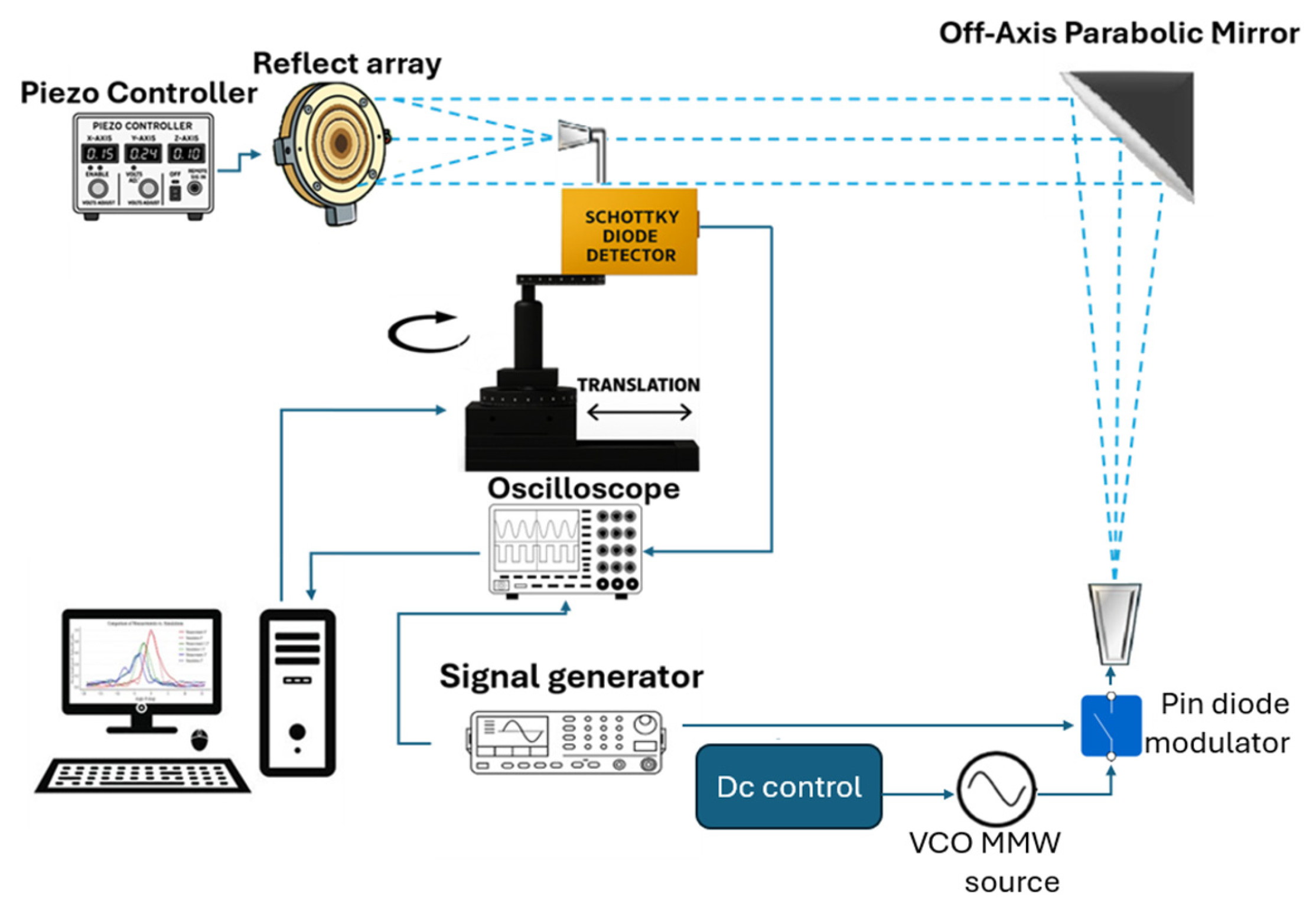
The experimental setup used to evaluate the REMR is shown in
Figure 5. A W-band VCO serves as a tunable millimeter-wave source operating from 78 to 82 GHz. The signal is amplitude-modulated using a PIN switch with on–off (square-wave) 1 kHz modulation. A W-band horn couples the radiation toward an off-axis parabolic (OAP) mirror, f = 150 mm, which collimates the beam and directs it onto the REMR. The beam reflected from the REMR is detected by a Schottky-diode detector fed by a waveguide probe; the probe’s active receiving area is 4.8 mm
2. The piezoelectric bimorph that rotates the continuous ground plane for steering is driven by a high-voltage piezo controller (MDT693B).
The detector output and the 1 kHz reference from the source/switch driver are monitored simultaneously on a digital oscilloscope. Because the Schottky detector produces a DC (envelope) output, the synchronous square-wave modulation acts as a lock-in–like reference, improving SNR and suppressing drift. A PC-side script retrieves the oscilloscope traces, computes the peak-to-peak amplitude of the received waveform at each position, stores the data, and then advances the stepper-driven stage—either a rotation stage for angular scans or a linear translation stage for axial scans—by one increment to acquire the next sample; this sequence repeats to build the scan and plot the results automatically.
3.2. Experimental Results
Numerical modeling (CST Studio Suite). All simulations were performed in CST Studio Suite. Initial dimensions were derived with an equivalent-circuit model and refined using unit-cell full-wave simulations in the frequency-domain solver with Floquet ports and periodic boundary conditions to extract reflection phase/magnitude across 78–82 GHz. The synthesized aperture phase distribution was then applied to a finite reflectarray model solved in the time-domain solver (FIT) with open boundaries.
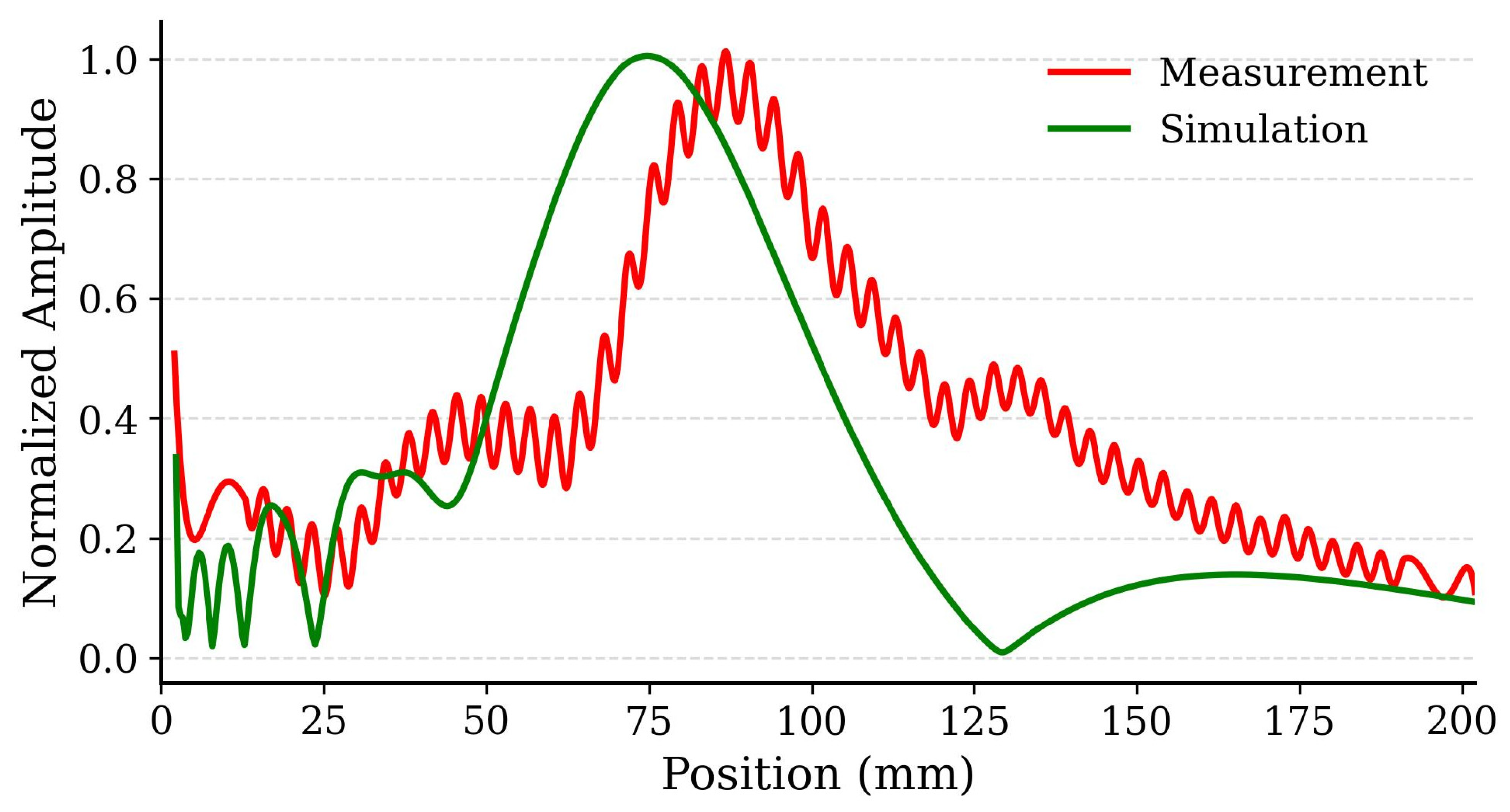
The focal point of the REMR, designed for 80 mm, was determined using a W-band Schottky barrier diode mounted on a translation stage moving along the axis shown in
Figure 5. The measured radiation power (solid red line in
Figure 6) is compared with simulation results (solid green line). While simulations predict a focal peak at 76 mm, the experimental maximum occurs at 81 mm, likely due to assembly tolerances and phase-quantization steps. Minor ripples near the transmit frequency, caused by internal reflections, can be mitigated by optimizing absorber placement or slightly offsetting the detector [
24].
Amplitude extraction and normalization. Measured amplitude is the detector peak-to-peak voltage. CST provides dB(DirTotal) (power in dB); to plot it on an amplitude scale we convert with dB = 20·log10(volt). All curves are then normalized to the global peak across measurement and simulation in the plotted span. In our data, 1.0 normalized = 54.37 detector units (peak at 0.0° in the 0° case).
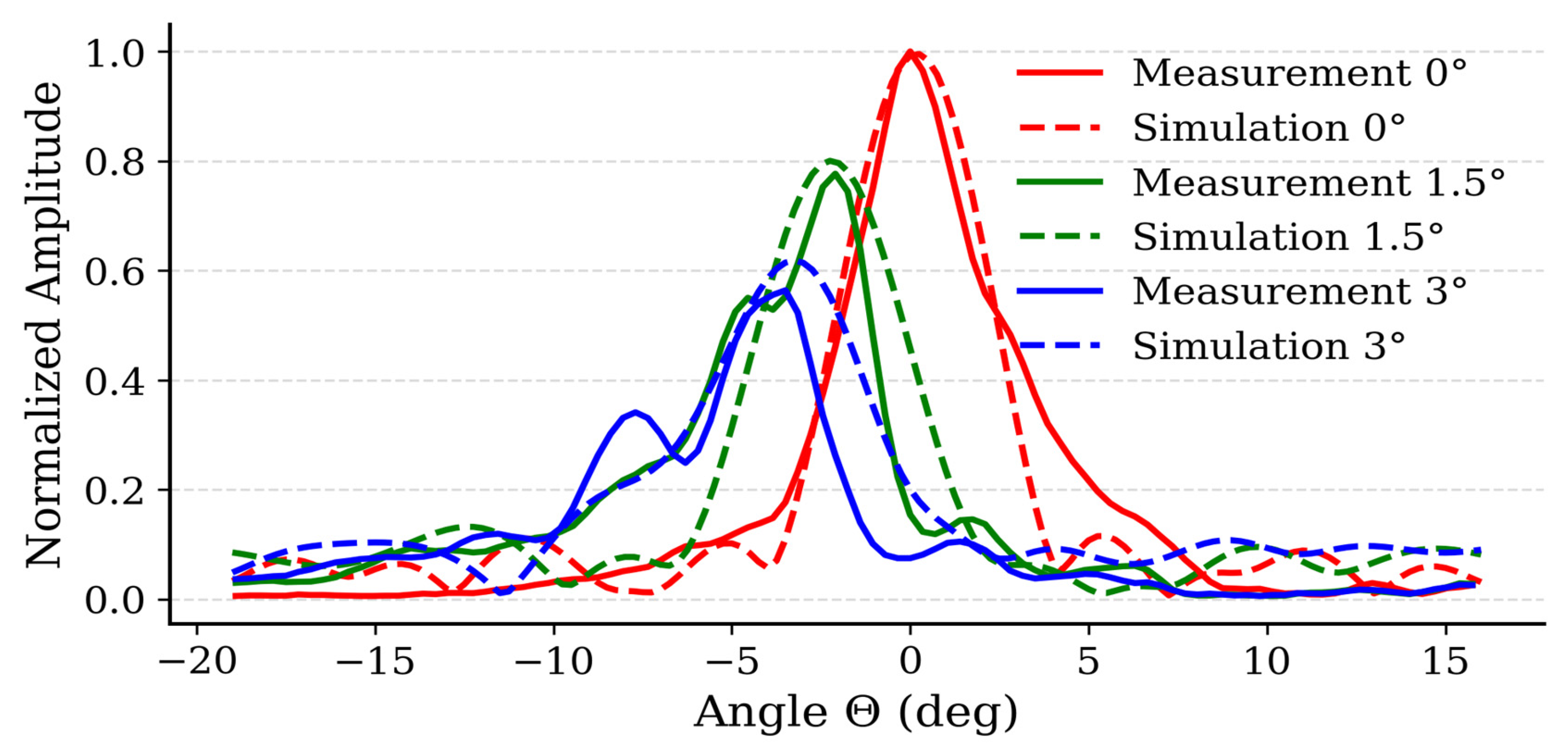
Beam steering of the REMER is shown in
Figure 7. In this experimental setup, a W-band Horn antenna was placed in the focal point (instead of the detector), and the direction of the reflected beam was measured using a W-band detector placed on a rotating stage.
Figure 7 shows the simulation results (dashed line), and the measured results for three tilting cases:
and
. The experimental results prove that a small tilting angle yields three times larger steering angle θ.
Ground-plane tilt produces predictable beam steering while maintaining high gain and low sidelobe levels.
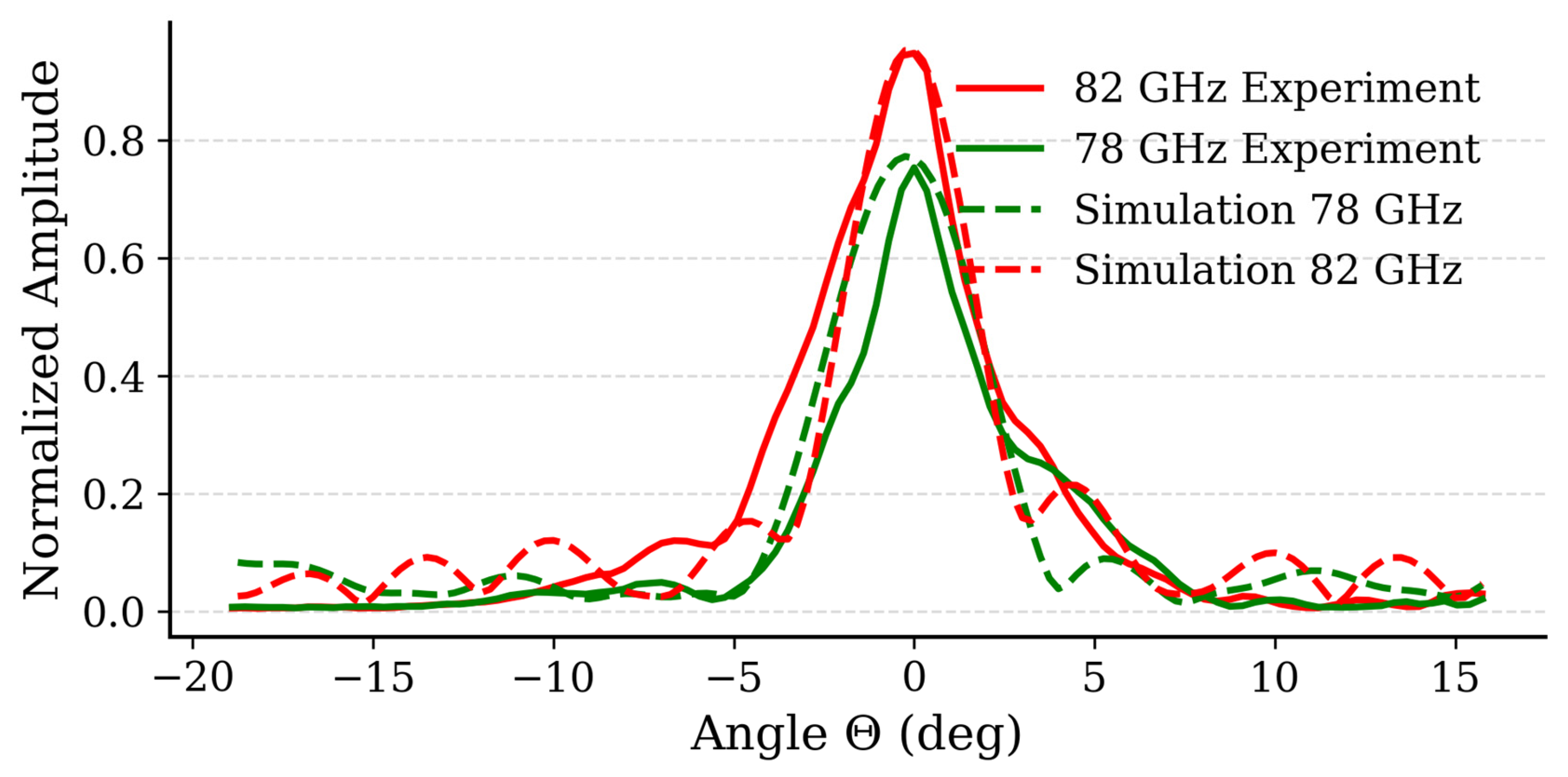
Tilting the ground plane to αr = under a fixed polarization plane () produces a smooth main-beam sweep from to . In particular, a tilting yields a beam deflection of roughly while a full tilt achieves steering. The measured directivity at 80 GHz were found to be in excellent agreement with the simulation results.
Figure 8 shows the far-field directivity patterns of the RERM for 78 GHz and 82 GHz. Both simulations (solid lines) and experimental results (dashed line) are in excellent agreement.
4. Discussion
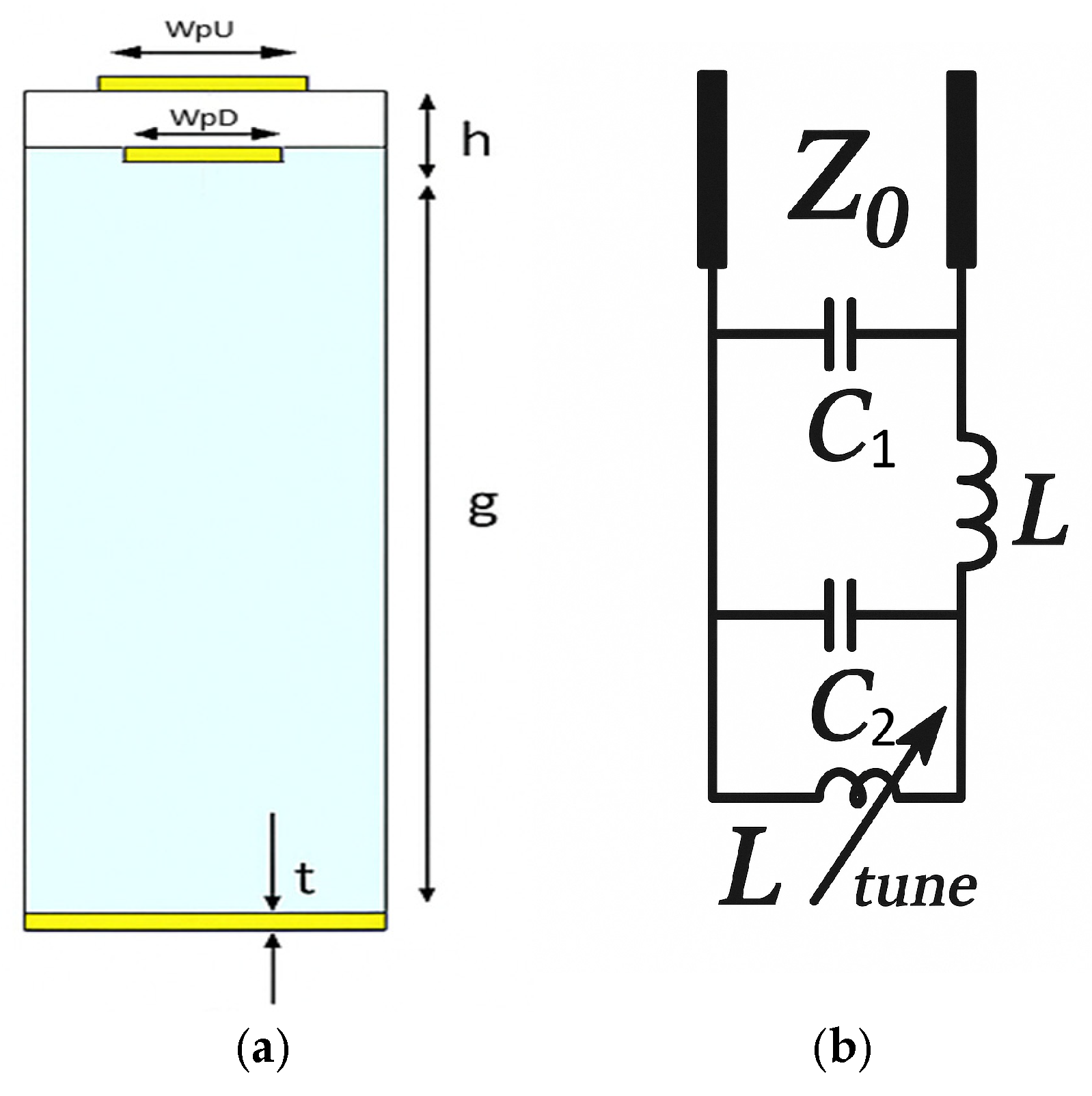
In this work, we present an additionally enhanced dual-patch unit cell that expands the operational bandwidth and removes the need for the conventional discretized ground grid, thereby simplifying fabrication and lowering costs. As illustrated in
Figure 9a, the cell comprises two coaxially aligned copper patches, an upper element (WpU) and a lower element (WpD), separated by a thin dielectric spacer. The lower patch is positioned above a continuous metal ground plane, with the intervening air gap g providing the principal tuning mechanism.
By superimposing two resonators, each tailored to slightly offset frequencies, their combined response yields a wider reflection bandwidth than a single-patch design [
24].
Figure 9b illustrates the updated topology equivalent circuit. The second patch introduces an additional shunt capacitance,
that increases the net capacitance
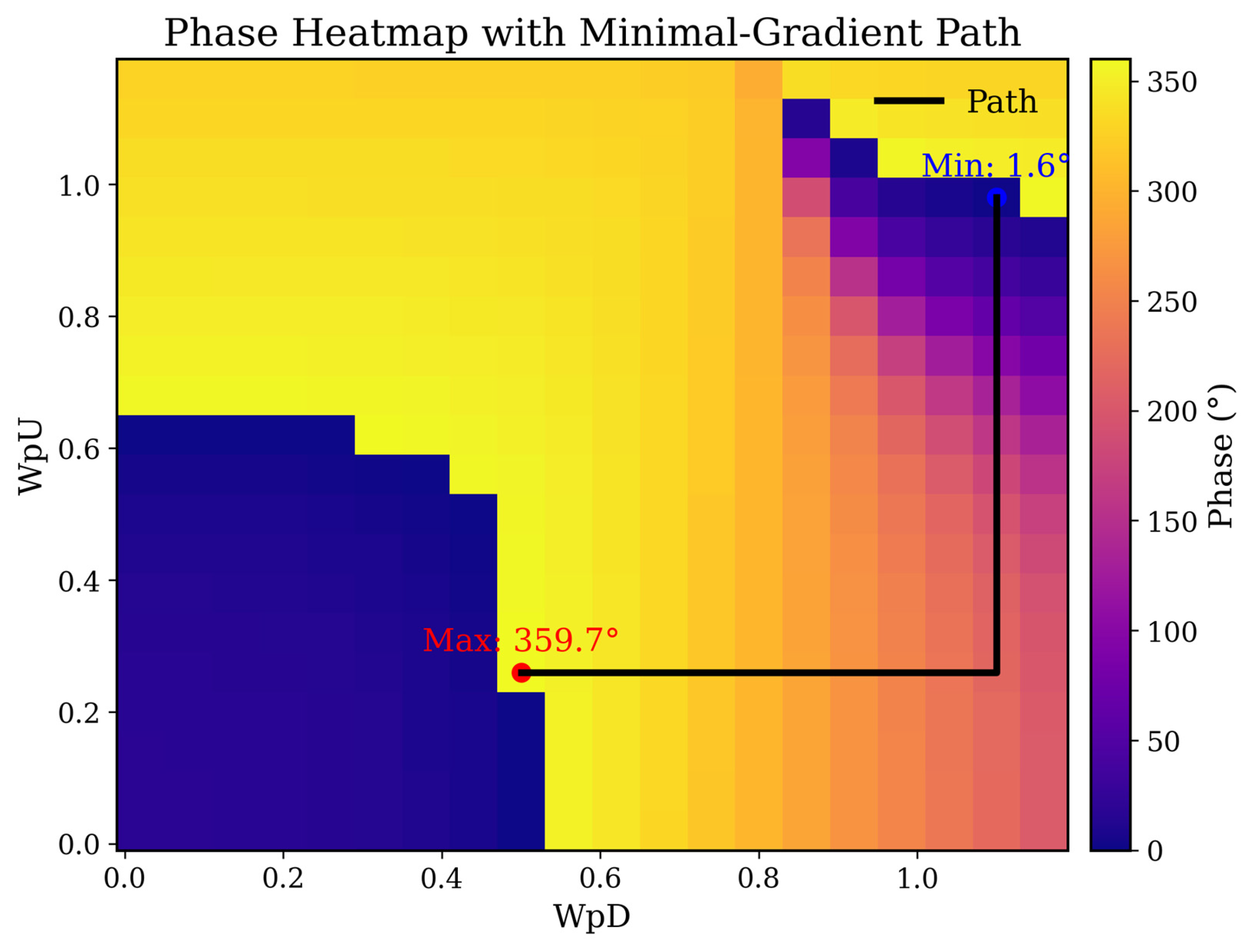
and adds an extra degree of freedom for better design. This technique smooths the reflection-phase response and yields a continuous tuning span exceeding
(
Figure 10), enabling finer phase granularity and more precise wavefront control. By adjusting the unit-cell geometry primarily patch sizes—we trade-off between quality factor
and phase coverage, consistent with small-antenna constraints (Chu’s bound and extensions [
25,
26]): reducing electrical size concentrates reactive energy and raises
(narrower bandwidth), whereas enlarging the patches lowers
and broadens the usable band. The adopted dual-patch configuration reflects this optimization, balancing phase range, bandwidth, and high reflection magnitude
, while simplifying fabrication relative to the first design and thereby reducing cost.
Figure 10 shows the aperture phase map
overlaid with a black path computed via Dijkstra’s algorithm. We use Dijkstra because, on a grid with non-negative edge weights defined by local phase differences, it provably finds the least-cost route and thus identifies the discrete path of minimal cumulative phase change (i.e., the least-gradient path), yielding the smoothest phase progression for stable beam steering.
Setting gap smaller,
makes
highly sensitive to variations in
Consequently, the resonant frequency from Equation (1) becomes much more responsive to
small changes in
now induce larger shifts in
. Because the reflection phase is tied to the detuning between the excitation frequency and
, a bigger frequency shift produces a greater phase change. In practice, this enhanced sensitivity means a 1° cam-rod rotation yields a 4° beam deflection, and a 1.25° rotation yields about 6° (
Figure 11), thanks to the added parallel
from the stacked lower patch and its amplified effect on
.
Table 2 compares the previously tested A/B-type reflector with the new dual-patch design at 80 GHz.
The dual-patch topology extends the usable phase range from 312° to 358° (near-full 360°), which reduces phase quantization error and improves wavefront fidelity. At the same time, reflection loss drops from <0.2 dB to <0.1 dB, benefiting link budget and thermal margin, and the operating bandwidth remains 78–82 GHz, indicating that the added degree of freedom does not compromise band coverage. Most notably, the steering range doubles from ±3° to ±6°.
Application scenarios and integration. The proposed REMR is a passive, high-power-capable mmWave aperture with low insertion loss, making it attractive where fine, fast beam “trim” is needed on top of a fixed boresight. In satellite communications, the REMR can be mounted in front of an existing horn and driven by a compact high-voltage piezo stage to provide small-angle pointing corrections that stabilize the line-of-sight against platform motion and mechanical disturbances, improving link margin without bulky gimbals. A simple calibration (voltage → angle) enables closed-loop control beacon tracking. The same drop-in integration applies to 6G E-band backhaul nodes and vehicle-/UAV-mounted terminals, where a few degrees of low-latency correction mitigate wind- and vibration-induced jitter.
We will fabricate an improved metasurface and retest it to validate a larger steering window and robustness. In parallel, we will extend the experimental protocol toward a practical implementation.
5. Conclusions
In this work, we designed, fabricated, and experimentally validated an E-band (78–82 GHz) reconfigurable metasurface reflect array (REMR) based on two complementary unit-cell types with a wide dynamic phase range and sub-dB loss. Using a piezoelectric bender to slightly rotate the continuous ground plane, the same aperture provides both focusing and controlled beam steering without bias networks or per-element tuning. The measured focal peak (~81 mm) is in close agreement with simulations (~76 mm), and the far-field patterns confirm predictable main-beam steering of about ±3°. Furthermore, we proposed and analyzed a new dual-patch unit cell that keeps the hardware simple (flat ground instead of a two-step ground), extends the usable phase coverage to ~358°, and increases the steering capability up to about ±6° while preserving low loss, low cost and manufacturability. These results validate the design method (equivalent-circuit insight, full-wave optimization, and code-based phase synthesis) and show that ground-plane rotation is an efficient, robust, and power-capable global actuation for wide-band, wide-aperture control.
