Abstract
This paper presents a comprehensive comparative analysis of high-voltage, high-frequency pulse generation techniques for Pockels cell drivers. These drivers are critical in electro-optic systems for laser modulation, where nanosecond-scale voltage pulses with amplitudes of several kilovolts are required. The study reviews key design challenges, with particular emphasis on thermal management strategies, including air, liquid, solid-state, and phase-change cooling methods. Different high-voltage, high-frequency pulse generation architectures including vacuum tubes, voltage multipliers, Marx generators, Blumlein structures, pulse-forming networks, Tesla transformers, switching-mode power supplies, solid-state switches, and high-voltage operational amplifiers are systematically evaluated with respect to cost, complexity, stability, and their suitability for driving capacitive loads. The analysis highlights hybrid approaches that integrate solid-state switching with modular multipliers or pulse-forming circuits as offering the best balance of efficiency, compactness, and reliability. The findings provide practical guidelines for developing next-generation high-performance Pockels cell drivers optimized for advanced optical and laser applications.
Keywords:
architectural comparison; electro-optic modulation; fast pulse rise time; generator for electro-optic modulation; high-frequency; high-voltage; Marx generator; performance analysis; Pockels cell driver; pulse driver technologies; pulse generation techniques; pulse generator; solid-state switches; switching-mode power supply; thermal management 1. Introduction
A Pockels cell driver is a specialized high-voltage, high-frequency pulse generator designed to control the polarization direction of light as it passes through a Pockels cell. The circuit architecture of a Pockels cell driver can vary significantly depending on the specific optical or electro-optic application, making it challenging to develop a universal driver that meets the wide range of performance and integration requirements. Pockels cell can be used in medical, scientific, and industrial lasers for beam modulation, for Q-switching of the laser cavity, and for pulse picking [1].
A Pockels cell behaves electrically as a capacitive load, with capacitance values typically ranging from 1 pF to 100 pF [2]. To effectively drive the Pockels cell, the pulse generator must be capable of delivering voltage pulses up to several kilovolts, with rise and fall times in the nanosecond range, to ensure precise modulation. In addition, the high-voltage driver must maintain extremely stable pulse amplitudes and durations [3] to achieve consistent optical switching performance.
The main structure of the high-voltage, high-frequency generator consists of a few basic parts: a high-voltage direct current step-up power supply, voltage multiplier circuit, high-frequency pulse-forming circuit, and a capacitive load such as a Pockels cell (see Figure 1) [4]. High-voltage DC step-up power supply can be powered either by an AC or DC power supply.

Figure 1.
High-voltage high-frequency pulse generator block diagram.
To ensure compatibility with various types of Pockels cells, the driver must support a wide range of operating parameters. Some cells require operating voltages below 1 kV, while others demand voltages exceeding 5 kV. The pulse repetition frequency can also vary significantly: from (100–200) kHz in some systems to as high as (1–2) MHz in high-speed applications. Rise and fall time requirements also differ: while certain use cases tolerate slower transitions, others require rise and fall times shorter than 2 ns. The driver must therefore be capable of generating fast, high-voltage pulses with precise amplitude control across a broad range of frequencies and load conditions.
Finally, compact and cost-effective designs are especially important for applications involving portable systems or space-constrained environments, where integration and form factor are critical considerations.
Existing market devices have a limited range of applications. Some operate only at low frequencies (up to 1 MHz), while others operate only at high frequencies (over 1 MHz). Likewise, certain devices handle low capacitive loads (up to 10 pF), while others support higher capacitive loads (over 10 pF). Voltage capabilities also vary: some devices do not exceed 1 kV, whereas others can deliver several kilovolts, but at low pulse repetition rates. Consequently, there is a lack of compact, cost-effective, reliable universal devices capable of operating across a wide frequency range and voltage levels while accommodating capacitive loads of varying ratings.
Following this comprehensive comparative analysis of high-voltage, high-frequency pulse generation techniques for Pockels cell drivers, a high-voltage, high-frequency pulse generator will be developed based on the specified parameters. The design will focus on delivering precise and stable high-voltage pulses, ensuring broad compatibility with various Pockels cells, maximizing driver efficiency, and maintaining long-term reliability. Particular emphasis will be placed on robust electrical and thermal performance, minimizing pulse rise and fall times, reducing physical size and cost, and implementing effective thermal management and stabilization.
The most commonly used architectures of high-frequency, high-voltage generator circuits designed to drive Pockels cells are as follows: vacuum tubes, voltage multiplier circuits, Marx generators, Blumlein structures, pulse-forming networks, Tesla transformers, switching-mode power supply-based high-voltage generator circuits [5,6,7], and solid-state switches.
Most of these architectures are complex in design and control due to the large number of components and high costs [8]. As a result, high-voltage metal-oxide-semiconductor field-effect transistors (MOSFETs) such as gallium nitride (GaN) or silicon carbide (SiC) devices are the most commonly used as switching elements in modern Pockels cell drivers due to their fast switching speeds, low output capacitance, and high breakdown voltages. Specialized pulse transformer circuits, avalanche transistor chains, or Marx generator configurations may also be combined with mentioned solid-state devices for generating ultrafast high-voltage transitions.
The rest of the paper is organized as follows: Section 2 presents the main challenges and thermal management in designing high-voltage high-frequency pulse generators for Pockels cells. Section 3 provides an overview of high-voltage high-frequency pulse generation methods. Section 4 presents a comparison of high-voltage high-frequency generator architectures. Based on these findings, Section 5 summarizes the contribution of the paper and provides an outlook for future work. Conclusions, abbreviations, and a list of references are provided at the end of the article.
2. Main Challenges and Thermal Management in Designing High-Voltage High-Frequency Pulse Generators for Pockels Cells
The primary objective in designing a pulse generator for Pockels cells is to deliver fast, high-voltage pulses with precisely controlled timing and amplitude to enable accurate modulation of light polarization. These pulses must exhibit nanosecond-scale rise and fall times, minimal jitter, and high stability to ensure reliable electro-optic switching.
As previously mentioned, high-voltage, high-frequency pulses can be generated using two main circuit components: a high-voltage source and a switching circuit responsible for pulse modulation (see Figure 1). From an electronics perspective, the Pockels cell is modeled as a near-ideal capacitor, and the driver must rapidly charge and discharge this capacitance through low-inductance paths to achieve sub-nanosecond edge transitions. This requires careful printed circuit board (PCB) layout design to avoid signal reflections and ringing.
Due to the high-frequency nature of the pulses, parasitic power losses occur in the switching circuits. High voltage combined with a fast repetition rate results in significant parasitic heat dissipation, which must be managed effectively. For instance, higher frequencies can be achieved by minimizing power losses. This can be achieved by using GaN FETs instead of SiC FETs, as GaN FETs have an extremely low gate charge figure of merit—approximately four times lower than that of SiC FETs [9]. To properly drive a Pockels cell, high-voltage pulses at frequencies around 1 MHz are required. As data rates continue to increase, even higher frequencies (exceeding 1 MHz) become necessary. Therefore, the driver switching circuit must be carefully designed to generate stable, high-voltage, fast-switching pulses [9]. Since both high voltage and high frequency directly affect driver performance, designing an efficient pulse driver presents numerous challenges. The main challenges in designing high-voltage, high-frequency pulse generators for Pockels cells include the following:
- Thermal management and stabilization [5,10];
- Achieving high-voltage pulse accuracy and stability [11];
- Ensuring compatibility with a wide range of Pockels cells, typically with capacitances ranging from 1 pF to 100 pF [2];
- Maximizing driver efficiency and long-term reliability [11] while maintaining robust electrical and thermal performance over time;
- Minimizing pulse rise and fall times, especially at kilovolt-level switching;
- Reducing physical size and cost [5].
One of the primary technical challenges is the rapid charging and discharging of the capacitive load represented by the Pockels cell—especially at high voltages. Any instability in this process can lead to inconsistent optical modulation and undesirable artifacts. Accurate and stable high-voltage pulses are essential, and maintaining a consistent device temperature is critical to achieving this. Temperature fluctuations during high-voltage, high-frequency operation can cause drift and instability in pulse characteristics [11].
Effective thermal management is essential for ensuring stable performance and dissipating the power losses associated with high-speed switching. Common strategies include heat sinking, forced air cooling, and liquid cooling. These methods help prevent thermal drift and ensure long-term operational reliability.
Driver efficiency and reliability are directly impacted by operating temperature [12]. All electronic components degrade over time, and this degradation accelerates at elevated temperatures. Therefore, high-voltage, high-frequency drivers should be equipped with efficient cooling systems and active temperature monitoring circuits [10].
Heat dissipation can be minimized by identifying its sources and addressing them at the component level. Selecting suitable driver components with low switching losses and evaluating package sizes and thermal resistances are crucial steps in this process [11]. After optimal components are selected, choosing the right cooling technology becomes critical. Various thermal management techniques exist, each with specific advantages and trade-offs—such as air cooling, solid-state cooling, liquid cooling, and phase-change cooling systems combined with proper thermal interface materials [13]. A thorough analysis of these methods is required to determine the most appropriate solution for the application.
2.1. Air Cooling
Air cooling is one of the most widely used and accessible thermal management methods in high-voltage pulse generators due to its simplicity, cost-effectiveness, and compatibility with high-voltage insulation requirements. Several air-cooling techniques are employed, each with specific advantages depending on the application:
- Natural and forced air cooling. Natural air cooling relies on passive convection to dissipate heat and is suitable for systems with low thermal output. In contrast, forced air cooling enhances heat dissipation using fans and heat sinks, making it effective for higher-power applications.
- Piezoelectric dual cooling jets. This method utilizes resonating piezoelectric disks to generate airflow with minimal power consumption. It is particularly advantageous for portable and space-constrained applications such as microelectromechanical systems (MEMSs) and LED drivers.
- Thermoacoustic cooling. In this technique, high-frequency acoustic waves generate airflow. While it offers a compact and mechanical-free solution, its low efficiency and limited cooling capacity restrict its use to small-scale systems.
- Electrohydrodynamic (EHD) cooling. EHD cooling employs corona discharge to induce airflow without moving parts, resulting in a quiet and efficient operation. However, due to insulation challenges posed by the high-voltage nature of the corona discharge, it is not commonly used in high-voltage applications.
2.2. Solid-State Cooling
Solid-state cooling technologies for high-voltage applications utilize conduction and thermoelectric effects to dissipate heat from electronic components without relying on fluids or mechanical parts. These techniques are particularly effective for compact systems and board-level thermal management. The main types of solid-state cooling include the following:
- Heat sinks with thermal interface materials (TIMs). This is the most common passive cooling method. Selecting an appropriate TIM is crucial to ensure efficient heat transfer and effective power dissipation [13].
- Thermoelectric cooling (TEC). TECs operate based on the Peltier effect, where heat is either absorbed or released at the junctions of dissimilar materials when electric current flows through them. This method offers precise temperature control, quick thermal response, compact form factor, and low noise operation. However, TECs are generally not suitable for high-power-density applications unless combined with supplemental cooling methods such as heat pipes, air, or liquid cooling systems.
2.3. Liquid Cooling
Liquid cooling systems remove heat from electronic components through the convection and conduction of a liquid coolant. These systems are particularly effective in high-power-density applications where air cooling or solid-state methods are insufficient. Common types of liquid cooling include the following:
- Immersion cooling. Entire circuits or specific components are fully submerged in a dielectric liquid such as mineral oil, silicone oil, fluorinated fluids, or deionized water. This allows direct heat transfer from the components to the liquid.
- Jet impingement cooling. High-velocity jets of dielectric coolant are targeted at thermal hotspots on components or PCB areas, providing efficient localized cooling.
- Cold plates and microchannel cooling. Cold plates or microchannel heat sinks are attached directly to heat-generating components. Liquid coolant is pumped through internal channels within these structures, efficiently carrying heat away from the source.
2.4. Phase-Change Cooling
Phase-change cooling utilizes the latent heat of vaporization or melting to absorb and dissipate heat. These techniques are highly effective for handling rapid thermal transients and high heat fluxes, making them particularly suitable for next-generation high-voltage pulse generators operating at high power levels and repetition rates. Common types of phase-change cooling include the following:
- Two-phase immersion cooling. Electronic components such as PCBs and transistors are fully submerged in a dielectric fluid that boils upon absorbing heat. The resulting vapor rises and condenses on cooler surfaces (e.g., vessel walls or heat exchangers) and then returns to the liquid phase, creating a passive, self-sustaining circulation loop.
- Heat pipes [14]. These are sealed metal tubes containing a small amount of working fluid (e.g., water or alcohol) and an internal wick structure. When heated, the fluid vaporizes and travels to the cooler end of the pipe, where it condenses and releases latent heat. The condensed fluid is then drawn back to the hot end via capillary action, enabling efficient heat transport.
- Solid phase-change materials (PCMs). These materials absorb or release thermal energy by melting or solidifying at specific temperatures. They are effective for buffering thermal spikes and maintaining temperature stability over short durations.
2.5. Summary of Cooling Methods
Effective thermal management is crucial for high-voltage pulse generators, and selecting the most suitable cooling method demands thorough analysis based on system requirements. Air cooling is one of the most accessible and cost-effective solutions, involving techniques such as natural and forced convection as well as more advanced approaches like piezoelectric dual jets, thermoacoustic airflow generation, and electrohydrodynamic cooling, each offering specific benefits depending on size constraints, efficiency, and application needs. Solid-state cooling relies on conduction and thermoelectric effects, making it well-suited for compact and board-level applications, with options including heat sinks combined with thermal interface materials and thermoelectric coolers that provide precise temperature control but may require additional support in high-power environments. Liquid cooling is highly effective for high-power density systems, utilizing methods such as immersion in dielectric fluids, high-speed jet impingement for targeted cooling, and cold plates or microchannel structures through which coolant is actively circulated to remove heat. Phase-change cooling takes advantage of the latent heat involved in vaporization or melting to manage sudden thermal spikes and intense heat loads, employing techniques like two-phase immersion in boiling fluids, heat pipes with internal wicks for vapor transport and condensation, and solid phase-change materials that melt or solidify at defined temperatures to stabilize system temperatures. The optimal cooling solution depends on balancing factors such as thermal load, spatial limitations, operational noise, and system complexity.
3. High-Voltage High-Frequency Pulse Generation Methods
3.1. Vacuum Tubes
Vacuum tubes were widely used for generating high-voltage pulses, especially before the advent of reliable high-power semiconductor switches. Although modern systems primarily utilize solid-state technology, vacuum tubes remain in use for specific applications that require high voltage, high frequency, or high-power pulsed operation due to their distinct advantages [15,16,17].
A key advantage of vacuum tubes is their ability to withstand extremely high voltages—often from kilovolts to megavolts—without electrical breakdown. They also provide fast switching performance, particularly in specialized types such as thyratrons and klystrons, making them well-suited for generating short-duration, high-power pulses. In addition, vacuum tubes are highly resistant to radiation, which makes them ideal for use in harsh environments such as nuclear facilities and space. Their capability to manage very high peak currents further contributes to their continued use in certain high-energy applications.
Various types of vacuum tubes are commonly employed in pulsed power applications, each serving a specific function. Thyratrons and krytrons, which are gas-filled tubes, function as high-speed switches and are frequently used in pulsed laser systems [18]. Klystrons are used to amplify radio frequency signals [15] and are typically found in particle accelerators and radar systems. Magnetrons, known for generating high-power microwave pulses [16,17], are widely used in radar applications and industrial microwave heating.
For instance, in radar modulators, a thyratron is used to quickly switch a high-voltage capacitor discharge through a magnetron, generating a powerful microwave pulse. These systems typically operate at voltages ranging from 20 to 50 kilovolts, with pulse durations in the microsecond range and repetition rates reaching several kilohertz.
Although solid-state technology has replaced vacuum tubes in most commercial and industrial applications, vacuum tubes are still used in certain military systems, high-energy physics experiments, and legacy equipment where their unique characteristics continue to offer advantages.
So historically, it is the oldest way to generate high-voltage pulses. Additionally, circuits using vacuum tubes are complex and challenging to implement [19]. Despite the mentioned advantages, there are simpler and more modern solutions, for example, solid-state technologies.
3.2. Voltage Multiplier Circuits
3.2.1. Cockcroft–Walton Voltage Multiplier
One of the simplest and most popular methods for generating high-voltage output is the use of a voltage multiplier circuit with the required number of stages. The Cockcroft–Walton voltage multiplier (CWVM) is a classic topology used for this purpose. It operates by stacking voltage stages composed of capacitors and diodes, effectively multiplying the input voltage across each stage. Each stage consists of two capacitors and two diodes (see Figure 2).
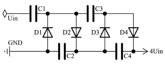
Figure 2.
Traditional Cockcroft–Walton voltage multiplier circuit diagram.
However, practical applications introduce several limitations. One major issue is the internal voltage drop, which increases with the number of stages [20], especially under higher loads. This drop depends on the capacitance, the frequency of operation, and the load current [21]. Low frequency and high load current increase the voltage drop and ripple, leading to inefficient voltage multiplication. Though the CWVM maintains uniform and relatively low voltage stress across components, it fails to deliver high output voltage efficiently at low frequencies, which limits its use in some applications.
Various modifications of this basic voltage multiplier topology exist, including the Karthaus–Fischer voltage multiplier (KFVM), Dickson voltage multiplier (DVM), hybrid Cockcroft–Walton and Dickson voltage multiplier (HCWDVM), and a capacitor–diode voltage multiplier type A (CDVM-A).
3.2.2. Karthaus–Fischer Voltage Multiplier
Another modification of the basic Cockcroft–Walton voltage multiplier (CWVM) is the Karthaus–Fischer voltage multiplier (KFVM), which features a parallel-cascaded architecture (see Figure 3). When comparing the voltage drops between the standard CWVM and the KFVM, both circuits exhibit a linear dependence on the load current, input frequency, and capacitance value. However, a significant distinction lies in their dependence on the number of stages in the cascade. For the CWVM, the voltage drop increases cubically with the number of stages, whereas for the KFVM, the increase is linear. As a result, the CWVM requires considerably higher capacitance values to compensate for voltage drop at an equivalent stage count [9]. Consequently, the KFVM offers a clear advantage by enabling the use of smaller capacitance values even with a greater number of stages.
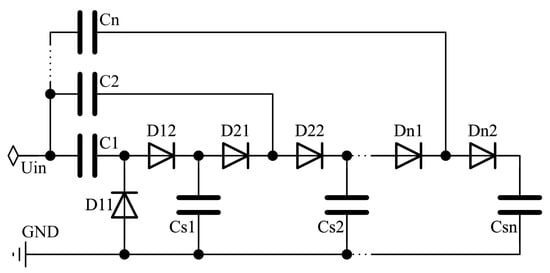
Figure 3.
Karthaus–Fischer voltage multiplier circuit.
3.2.3. Dickson Voltage Multiplier
The Dickson voltage multiplier (DVM) is also known as the Dickson Charge Pump. It consists of a series of capacitors and charge transfer switches (typically implemented with diodes or MOS transistors) arranged to incrementally boost the voltage from one stage to the next. In the CWVMO circuit, the capacitors are connected in series and can generate high voltage with low voltage stress. In this DVM circuit, the capacitors are connected in parallel (see Figure 4) so the voltage stress increases as the number of stages increases [20]. One of the key advantages of the DVM is its better performance in the low frequencies, where it exhibits lower output resistance and faster settling time compared to the CWVM. However, in high frequencies, while it still performs well, it tends to consume more energy and settles slower than the CWVM [22]. Moreover, the Dickson multiplier has a higher equivalent self-capacitance, which can slow its response under certain load conditions. Despite this, the DVM remains a reliable and integrable solution for many low-power applications.
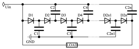
Figure 4.
Dickson voltage multiplier circuit.
3.2.4. Hybrid Cockcroft–Walton and Dickson Voltage Multiplier
As previously mentioned, the Cockcroft–Walton Voltage Multiplier (CWVM) uses a topology in which capacitors are connected in series. This configuration allows the generation of high voltage with relatively low voltage stress on each component. However, a key drawback of CWVM is that its power efficiency decreases as the number of circuit stages increases. In contrast, the Dickson Charge Pump (DCP) features a topology where capacitors are connected in parallel, resulting in higher power efficiency compared to CWVM. Nevertheless, due to the parallel capacitor configuration, DCP suffers from increased voltage stress as the number of stages grows. In addition to these trade-offs, both CWVM and DCP share the common limitation of slow circuit speed. To address this, a Hybrid Cockcroft–Walton and Dickson Multiplier topology was developed (see Figure 5). This hybrid configuration offers the advantage of reduced voltage stress on circuit components compared to the traditional Dickson voltage multiplier [23]. It combines a stacked Dickson multiplier with a series-connected Cockcroft–Walton voltage multiplier [24].

Figure 5.
Hybrid Cockcroft–Walton and Dickson voltage multiplier circuit.
3.2.5. Capacitor Diode Voltage Multiplier Type A
Another type of voltage multiplier topology has been developed, known as the capacitor diode voltage multiplier type A (CDVM-A) (see Figure 6). In this configuration, as a result, CDVM-A provides continuous power delivery to the load throughout the cycle, leading to reduced output current ripple. However, similar to CWVM, CDVM-A experiences internal voltage drop as the number of stages increases. Additionally, one major drawback of this topology is that it requires more stages and therefore more components to achieve the same output voltage as the CWVM.
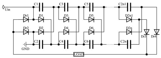
Figure 6.
Capacitor diode voltage multiplier type A circuit.
The voltage stresses across the capacitors in both CWVM and CDVM-A topologies are low and uniformly distributed across all stages. This allows the use of capacitors with identical voltage ratings, simplifying component selection. In contrast, the Dickson voltage multiplier (DVM) and hybrid Cockcroft–Walton and Dickson voltage multiplier (HCWDVM) require capacitors with varying voltage ratings and sizes, adding complexity to the design and development process. Although CWVM and CDVM-A topologies typically cannot generate output voltages in the tens of kilovolts due to significant internal voltage drops, they benefit from uniformly low voltage stress on components. However, the internal voltage drop can be significantly reduced by using a high-frequency input. For a given capacitance value and number of stages, increasing the input frequency decreases the internal voltage drop, enabling CWVM and CDVM-A to produce output voltages in the tens of kilovolts range [21]. Additionally, a higher operating frequency allows for the use of smaller capacitors, thereby reducing the overall size and cost of the device.
3.2.6. Summary of Voltage Multiplier Circuits
The voltage multiplier circuits discussed above consist solely of passive components and are commonly used to generate high-voltage outputs through multiple stages of capacitors and diodes [3]. Each of these mentioned voltage multiplier topologies has its own advantages and disadvantages. The CWVM is a classic design with low and constant voltage stress across components but suffers from increasing internal voltage drop with more stages, especially under low-frequency and high-load conditions. The KFVM improves on CWVM by offering a linear voltage drop with stage count, enabling smaller capacitance values. The DVM uses parallel-connected capacitors, offering better performance at low frequencies but increasing voltage stress with additional stages. To balance the trade-offs, the HCWDVM combines both topologies, lowering voltage stress while maintaining performance. Finally, the CDVM-A ensures continuous power delivery and low ripple, but requires more stages and components to achieve the same output voltage as the CWVM.
3.3. Marx Generator
Another method for generating high-voltage pulses is the use of a Marx generator circuit (see Figure 7), first introduced in 1925 by Erwin Marx [25]. A traditional Marx generator operates by charging capacitors in parallel and then discharging them in series to achieve voltage multiplication. Early Marx generator designs relied on spark gaps to trigger the discharge. These configurations are primarily suited for single-shot or low-repetition-rate applications and are constrained by slow recharge times and limited control precision.
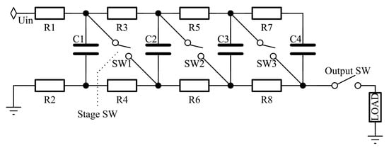
Figure 7.
Traditional Marx generator circuit diagram.
Over time, the basic Marx generator topology has evolved, with various modifications developed to improve its performance and adapt it to specific applications [25]. Solid-state devices such as MOSFETs and IGBTs have replaced spark gaps to improve generator efficiency and reliability. The earliest topologies used BJTs (see Figure 8). Like traditional Marx generators that use spark gaps, when the avalanche transistor in the first stage is triggered ON, it causes a chain reaction where the remaining transistors break down sequentially due to overvoltage. This results in the generation of negative high-voltage nanosecond pulses across the load. Because avalanche transistors have limited voltage and power handling capabilities, this type of Marx generator is not well-suited for applications that demand high-power or long-duration pulses. Additionally, as the number of stages increases, the load-handling capacity decreases because of the equivalent ON-state resistance of the series-connected avalanche BJTs. In this configuration, capacitors are still charged in parallel using high-impedance resistors or inductors and then discharged in series to the load, following the principle of traditional Marx generators.
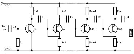
Figure 8.
Marx generator circuit with BJTs.
Modern topologies use IGBTs/MOSFETs in half-bridge or full-bridge configurations (see Figure 9). A schematic of the three-stage generator using six IGBT switches in each stage is provided. There is one additional capacitor. This topology enables at least two paths to charge the capacitors in parallel. When the discharge switches Sai and Sci are activated, capacitors C1, C2, and C3 discharge in series to the load, producing a positive pulse. On the other way, when Sbi and Sdi are turned on, capacitors C2, C3, and C4 discharge in series, generating a negative pulse. As a result, this configuration enables the generation of bipolar pulses with variable widths.
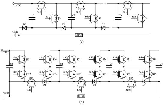
Figure 9.
Marx generator circuit with (a) half-bridge and (b) full-bridge configuration.
In these configurations, the charging circuits have been upgraded from passive to active switching, resulting in a slight improvement in overall efficiency. Different types of semiconductors are preferred depending on the application: IGBTs are chosen for high-power uses because of their higher voltage capacity and durability, while SiC MOSFETs are preferred for their fast switching speeds and high-frequency operation. Synchronizing all stages is crucial to prevent failures. These topologies can effectively drive resistive, capacitive, and inductive loads.
Today, there are more ways to implement the classic Marx generator circuit. For instance, a capacitor-chopping circuit [26] based on the traditional Marx generator topology (see Figure 10) can produce narrower high-voltage pulses (below 10 ns) compared to the traditional design [27].

Figure 10.
Capacitor-chopping circuit based on traditional Marx generator topology.
During the charging state, the main switches are OFF, the chopping switches are ON, and all capacitors are charged in parallel to input voltage. During the Pulse-ON stage, all switches are ON and all capacitors are connected in series. During the Pulse-OFF (chopping) stage, the main switches are ON, and the chopping switches are OFF, so we have a situation where the Cmain and Cchop of each stage are connected in series with opposite polarity. As a result, the output from each stage goes to 0 V.
After analyzing the operating principle, it is clear that the proposed capacitor-chopping circuit demonstrates the same rising and falling edges as the traditional Marx circuit, with the key difference being its ability to produce a shorter pulse duration (see Figure 11).

Figure 11.
Capacitor-chopping circuit effect on pulse duration.
One modification of the Marx generator is the boost-Marx pulse generator (BMPG) (see Figure 12), which is designed to generate high-voltage nanosecond pulses efficiently. As previously mentioned, a traditional Marx generator charges capacitors in parallel and discharges them in series to achieve voltage multiplication. In the BMPG design, each stage includes a SiC MOSFET switch, an energy storage capacitor, and diodes to control the direction of current flow. Additionally, an inductor is incorporated for both energy storage and high-voltage isolation. This inductive isolation reduces losses and allows faster switching by replacing the traditional resistive isolation. An additional switch (S0), combined with an inductor (L), functions as a boost stage, further increasing the output voltage. Using this architecture, the system achieved 200–1000 ns pulse widths, with a 10 kV output amplitude and repetition rates up to 10 kHz [28]. The main advantages of this design are its higher efficiency and improved scalability without the need to increase the voltage ratings of individual components.

Figure 12.
Boost-Marx generator circuit diagram.
Additionally, self-triggering Marx generator topologies (see Figure 13) have been developed for high-frequency pulse generation. In the charging mode, all MOSFETs remain OFF, and all capacitors are connected in parallel, charged to the same input voltage level. During the discharge mode, when switch S4 turns ON, capacitors Ciss3 and Ctr3 are charged by capacitor C4. This causes the voltage across Ciss3 (VCiss3) to reach the threshold level, thereby turning ON switch S3. This sequence continues, turning ON all switches one after another. In the turn OFF phase, each switch turns OFF when the voltage across the gate-source capacitor (Cgs) drops below the threshold voltage. The turn OFF time is slightly longer than the turn ON time due to the relatively low threshold voltage of the switches.

Figure 13.
Self-triggering Marx generator circuit diagram.
This topology offers a significant advantage: the multistage Marx circuit requires only a single gate driver, which does not need high-voltage isolation. It can generate a high-voltage pulse output through multistage stacking without the need for complex isolated drive circuits. However, experimental results indicate that these designs typically achieve rise times of around 45 ns, which is too slow for applications requiring high repetition rates [29].
The BMPG represents a modern advancement of the traditional Marx generator, delivering enhanced output voltage and frequency performance through inductive boosting and modular solid-state switching. Solid-state Marx generators are evolving to become more compact, modular, and intelligent. Ongoing and future developments aim to achieve megahertz-range repetition rates [30], integrate smart fault detection into highly compact designs, enable parallel and series stacking of stages for ultra-high voltage generation, and adopt wide-bandgap semiconductor technologies such as SiC and GaN to enhance efficiency and thermal performance.
3.4. Blumlein Structure
The Blumlein architecture is a specialized type of pulse generator commonly used in pulsed power systems, particularly where nanosecond high-voltage pulses are required—such as in bioelectrics for electroporation and other biomedical applications. A Blumlein generator typically consists of two transmission lines of equal length connected to a load, along with a high-voltage power supply, a charging resistor, and a closing switch (see Figure 14).
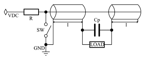
Figure 14.
Circuit diagram of a Blumlein pulse generator.
When the switch is activated, the energy stored in the transmission lines is discharged simultaneously into the load, producing a high-voltage rectangular pulse. The pulse duration is determined by the length of the transmission lines [31], making the architecture inherently inflexible for applications that require variable pulse widths.
Advantages:
- High output voltage, typically reaching up to tens of kilovolts;
- High repetition rates, ranging from 200 kHz [23] to 5 MHz in advanced designs.
Disadvantages:
- Limited pulse duration flexibility due to the fixed length of the transmission lines;
- Relatively slow slew rates, with typical rise and fall times around 20 ns [32].
In summary, the Blumlein architecture is a valuable and reliable solution for generating short, high-voltage pulses in modern pulsed power applications. However, its inability to produce variable pulse durations limits its use in scenarios where pulse width adjustability is essential.
3.5. Pulse-Forming Network
A pulse-forming network (PFN) is an electrical circuit consisting of inductors (L) and capacitors (C) configured to produce a rectangular or specifically shaped high-voltage pulse. PFNs are particularly useful in applications that require a flat-top pulse, as opposed to the exponentially decaying pulses commonly generated by traditional Marx generators.
Pulse-forming networks can be classified into three fundamental types (see Figure 15). Type A and Type B both use equal inductance and capacitance values in each section. Type C (called Guillemin Network) employs calculated variations in inductance and capacitance for each stage to more accurately approximate a square waveform. The component values are derived using the following equations:
These calculations are based on Fourier series synthesis, allowing type C PFNs to generate a more uniform and controlled pulse shape.
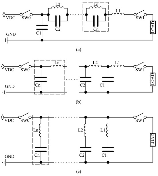
Figure 15.
Pulse-forming network circuit diagrams: (a) type A; (b) type B; (c) type C.
Disadvantages: fixed pulse width, poor pulse quality, limited load capability, and output voltage constraints, typically delivering only half of the DC charging voltage across a matched load.
To overcome the mentioned disadvantages, some hybrid configurations have been developed:
- PFN combined with switches and modulation resistors [24];
- PFN combined with transformer—boost output voltage, but increases cost and size;
- PFN combined with Marx circuit—combines the waveform shaping of PFNs with the voltage multiplication of Marx circuits;
- PFN combined with boost converter—improves both amplitude and energy efficiency.
These hybrid designs offer a balance between compactness, performance, and flexibility, enabling voltage step-up, better pulse shaping, and enhanced adaptability for various high-voltage applications.
Pulse-forming networks are a fundamental technology in high-voltage pulse generation. Although they offer less flexibility and generally produce lower output voltages compared to some modern topologies [33], they provide several key advantages:
- Simple and reliable design;
- Consistent and well-defined pulse shapes;
- Compatibility with modern power electronics.
PFNs remain highly relevant, particularly when integrated with advanced switching technologies or voltage multiplier circuits, enabling them to meet more demanding application requirements while maintaining a compact and efficient form factor.
3.6. Tesla Transformer (Magnetic Circuits)
A Tesla transformer is a specialized type of pulse transformer used in pulsed power systems, featuring either an air-core or an open magnetic core [5]. It comprises two coupled resonant circuits—primary and secondary windings—tuned to the same or closely matched resonant frequencies. This configuration enables efficient resonant energy transfer, resulting in the generation of high-voltage pulses at the output. Tesla transformers are generally classified into two main types: air-core and open-magnetic-core designs.
An air-core Tesla transformer consists of two coupled coils—primary and secondary—without a magnetic core. These transformers are lightweight, compact, and free from the risk of magnetic saturation, making them well-suited for high-frequency applications. However, their main limitation is a low coupling coefficient, typically less than 0.8, which reduces energy transfer efficiency.
To address this issue, the open-magnetic-core Tesla transformer was developed. In this design, the inner and outer conductors of the pulse-forming line (PFL) are replaced with an open magnetic core, significantly improving the coupling efficiency compared to the air-core configuration.
A typical air-core Tesla transformer consists of two coupled resonant circuits tuned to the same or nearly identical resonant frequencies, enabling efficient energy transfer between the primary and secondary coils (as illustrated in Figure 16).

Figure 16.
Double resonance circuit of Tesla transformer.
Tesla transformer-based circuits are suitable for compact high-voltage pulse generation, repetitive pulse operations, systems requiring lightweight, core-free pulse transformers, pulsed lasers, accelerators, and high-voltage research setups.
Tesla transformer-based circuits provide a compact and efficient solution for generating high-voltage pulses at high repetition rates. Air-core designs are preferred for their lightweight construction and suitability for high-frequency operation, whereas open-core variants offer enhanced energy transfer efficiency and higher voltage transformation. Ongoing advancements in materials, winding configurations, and topological integration continue to expand the performance and versatility of these systems in modern pulsed power applications.
3.7. Switching-Mode Power Supply-Based High-Voltage Pulse Generation Circuits
In the context of high-voltage pulse generators (HVPGs), a Switched-Mode Power Supply (SMPS) is a power conversion system that utilizes high-frequency switching to step up voltage, shape output pulses, and provide greater control flexibility. Unlike traditional topologies, SMPS-based HVPGs employ semiconductor devices (e.g., MOSFETs, IGBTs) and magnetic components to generate fast, high-repetition-rate pulses with improved efficiency and compactness.
In flyback (a) and forward-type (b) switching power supply topologies (see Figure 17), transformers are used to step up the voltage and provide galvanic isolation between input and output. In these designs, energy is temporarily stored in the transformer core and then transferred to the load. RCD snubber circuits are used to clamp unwanted voltage spikes caused by transformer leakage inductance. These topologies are widely recognized for their simplicity, compact size, and effectiveness in isolated high-voltage applications.

Figure 17.
Switched-Mode power supply circuit diagram: (a) flyback-type topology; (b) forward-type topology.
Buck-boost-based high-voltage power supply topologies (see Figure 18) use a combination of a switch, diode, and capacitor to either step up (boost) [6] or step down (buck) the voltage level. This topology is naturally modular, allowing multiple stages to be cascaded to achieve higher output voltages.
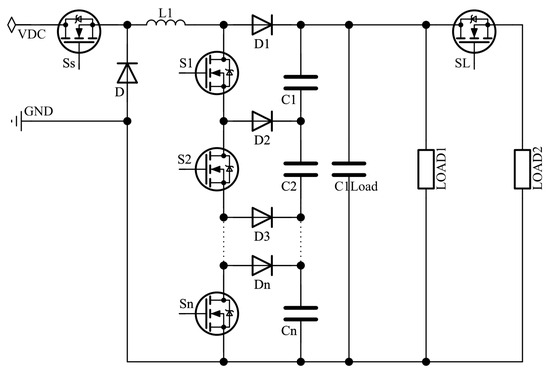
Figure 18.
Buck-boost-based pulse generator circuit diagram.
The boost-inverter-based bipolar pulse generator topology combines two bidirectional boost converters (see Figure 19). The load is connected differentially between their outputs. This configuration enables the generation of bipolar pulse outputs using only two high-voltage switches. Compared to traditional full-bridge designs [7,34], it offers a simpler and more cost-effective solution.
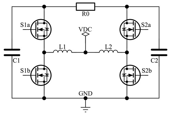
Figure 19.
Boost-inverter-based pulse generator circuit diagram.
Advantages of switching-mode power supplies-based high-voltage pulse generators: compact size, high output voltages, high repetition rates, and stable and precise control of the pulse width and waveform.
Key challenges in high-voltage SMPS design:
- Switch selection—semiconductor switches must withstand high voltage and current stress while offering fast and reliable performance. Wide-bandgap devices such as SiC and GaN are promising options.
- Parasitic effects—minimizing parasitic inductance and capacitance is critical, as they can degrade switching speed and distort pulse waveforms.
- Thermal management—effective cooling and heat dissipation are essential for maintaining reliability and performance.
- Gate driver design—gate drivers must be optimized for fast, synchronized switching under high-voltage conditions.
- Integration with other stages—SMPS can be combined with pulse-forming networks or voltage multiplier circuits to enhance output voltage and pulse characteristics.
In summary, switching-mode power supplies offer a flexible, efficient, and compact solution for high-voltage pulse generation. When integrated with voltage multipliers or pulse-shaping stages, switching-mode power supplies-based systems can deliver high-performance, modular, and precisely controlled pulses, making them ideal for a wide range of advanced pulsed power applications.
3.8. Solid-State Switches
A solid-state switching power generator (SPG) is an electronic power source that efficiently controls and converts electrical energy using semiconductor switches, such as transistors, IGBTs, or MOSFETs [35]. These generators are capable of delivering high-voltage pulses to the Pockels cell. The most effective solutions for high-frequency, high-voltage pulse generation are outlined below.
Silicon (Si) MOSFETs, as the most mature technology, offer advantages such as low cost, a well-established manufacturing infrastructure [36], and strong compatibility with surface-mount technology [37]. They perform reliably at low-to-moderate voltages but face limitations under high-voltage and high-temperature conditions [38]. Key benefits of Si devices include ease of use, affordability [39], and market maturity, which provides a wide selection of optimized models for various power levels [37]. However, their drawbacks include slower switching speeds, poor high-temperature performance [40], higher conduction and switching losses, and limited suitability for high-frequency, high-efficiency applications [41]. These limitations reduce their effectiveness in next-generation power electronics that require greater efficiency and power density [42].
Super-Junction (SJ) MOSFETs represent an advanced evolution of silicon (Si) technology, combining low on-resistance with enhanced voltage-blocking capabilities compared to conventional Si MOSFETs [41]. These devices are optimized for high-voltage applications, typically in the 600–900 V range [43], and offer superior efficiency and faster switching speeds within this voltage window [43]. SJ MOSFETs are well-suited for switching frequencies in the hundreds of kilohertz. However, they face challenges at higher frequencies due to increased gate charge and greater reverse recovery losses at MHz-level switching [39]. As a result, SJ MOSFETs remain less effective than SiC and GaN devices in high-speed, high-voltage applications [41].
Silicon carbide (SiC) MOSFETs offer significant advantages over traditional silicon devices, including a higher breakdown voltage, wider bandgap, and superior thermal conductivity [42]. These properties enable lower on-resistance, faster switching speeds, and improved heat dissipation compared to Si-based MOSFETs [41]. As a result, SiC devices deliver higher efficiency and support greater switching frequencies with extremely fast rise and fall times [18]. However, under hard-switching conditions at high drain currents, SiC MOSFETs can experience higher turn-off losses compared to GaN devices [44]. Also, SiC devices are relatively expensive and often require specialized gate drivers to prevent reliability issues like short-circuit failure [38]. Their higher gate charge and input/output capacitances, relative to GaN FETs, also limit their effectiveness at extremely high frequencies [39].
The Thick Central Oxide MOSFET (TCOX) enhances the performance of standard SiC devices by incorporating a thick central oxide layer, which increases breakdown voltage and reduces gate charge. It also offers improved reverse recovery characteristics and slightly better thermal stability. The Super-Junction Thick Central Oxide MOSFET (SJ-TCOX) integrates a super-junction structure into the TCOX design, resulting in significant performance gains. It achieves the lowest specific on-resistance, indicating reduced conduction losses. The reverse transfer capacitance is minimized to just 0.05 pF, and the gate charge is reduced to 3.41 nC, leading to the lowest switching energy losses among all devices studied [45]. Additionally, it maintains a high breakdown voltage of 1450 V. These enhancements contribute to a superior high-frequency figure of merit and improved overall power conversion efficiency. The key advantage of the SJ-TCOX MOSFET is its balanced optimization of both static and dynamic characteristics, making it well-suited for power switching applications that demand fast switching, low losses, and high voltage resilience. The only potential drawback is the increased structural and fabrication complexity due to the super-junction design and the need for precise doping control, which may raise manufacturing costs and complexity.
Gallium nitride (GaN) FETs offer the fastest switching speeds among the solid-state devices discussed, primarily due to their low input and output capacitances and high electron mobility [36]. Their lateral structure and fast carrier dynamics result in minimal reverse recovery charge and extremely rapid voltage transitions [44]. Key advantages of GaN devices include low switching losses, efficient high-frequency operation in the MHz range [39], and the potential for reduced size of passive components [41]. However, GaN has lower thermal conductivity than SiC, which can limit its performance under harsh or high-temperature conditions [43]. GaN transistors also require precise gate control and robust protection mechanisms to prevent degradation under fault or overstress conditions [40]. Additionally, GaN technology is relatively newer, with less long-term reliability data and higher cost compared to Si, though potentially lower than SiC depending on the application.
Gallium oxide (Ga2O3) is an emerging ultra-wide-bandgap semiconductor material that offers a higher critical electric field than both SiC and GaN [42]. It shows strong potential for enabling ultra-high-voltage devices at a lower cost, primarily due to the feasibility of large-area, low-cost substrate fabrication. However, Ga2O3 remains in the early stages of research and development. Its relatively low thermal conductivity and limited device maturity, compared to SiC and GaN, present significant challenges for thermal management and practical deployment in power electronics.
Vertical GaN and Ga2O3 devices are emerging as promising solid-state technologies for future high-power applications [38]. Vertical GaN aims to leverage the superior material properties of GaN within a vertical architecture, enabling voltage ratings exceeding 1.2 kV. While this approach shows significant potential, it remains in the early stages of development, with limited commercial availability. Ga2O3, an ultra-wide-bandgap semiconductor, offers exceptionally high breakdown fields, making it suitable for ultra-high-voltage device design. However, its extremely poor thermal conductivity limits current-carrying capability and thermal stability, posing a major challenge for practical use in high-power systems.
Various types of semiconductor devices offer different performance characteristics. Silicon (Si) MOSFETs are affordable and widely available but struggle with high voltage and frequency performance. Super-Junction (SJ) MOSFETs improve on Si with better efficiency and voltage handling but still fall short at very high frequencies. Silicon carbide (SiC) MOSFETs provide excellent efficiency, high voltage, and thermal performance, though they are more expensive and complex to operate. Advanced variants like TCOX and SJ-TCOX MOSFETs further improve SiC performance, offering very low losses and high voltage capability, though this comes with greater fabrication complexity. Gallium nitride (GaN) FETs offer the fastest switching speeds and excellent high-frequency performance, but they have thermal limitations and require precise control. Gallium oxide (Ga2O3), a newer ultra-wide-bandgap material, promises ultra-high-voltage operation at lower cost, though it currently lacks thermal stability and technological readiness. Vertical GaN and Ga2O3 devices are also in early development, showing potential for high-power applications but facing challenges in thermal management and commercialization.
There are numerous ways to use semiconductor devices for high-voltage pulse modulation. Solid-state devices can be connected in series to distribute the applied high voltage among themselves. However, the reliability of this series connection is not very high. One of the key issues is that individual devices in the series may turn on slightly earlier or later than others due to parasitic components and variations between the devices. If this situation occurs, the high voltage is not divided between series devices properly, and the high-voltage pulse modulation device fails. It is possible to eliminate this failure by using additional components in control circuits [46], but this increases the overall cost of the system. IGBTs can be used in this configuration, but typically these devices are not well-suited for driving loads at high frequencies. There is a proposed specific pulse modulator circuit using MOSFETs [4] and two separate high-voltage supplies. This configuration is more reliable than the previously mentioned series-connected circuit and is capable of ensuring fast pulse switching at high repetition rates.
Several different high-voltage switching circuits using MOSFETs are discussed in [18,47]. The first approach involves the simplest single-switch circuit operating with a unipolar power supply (see Figure 20a). It is obvious that a single MOSFET control circuit is not an effective solution. Additionally, this circuit is unsuitable for high repetition rates due to long pulse fall times, which depend only on the RC discharge time (determined by the Pockels cell’s capacitive and resistive loads).
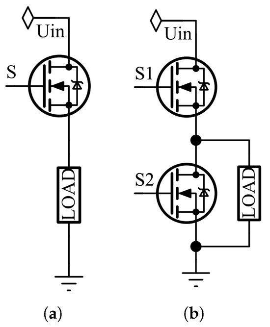
Figure 20.
(a) Single-switch circuit; (b) push–pull circuit.
The second proposed high-voltage pulse driving circuit [18] is a push–pull MOSFET configuration (see Figure 20b). In this design, the Pockels cell’s internal capacitive load can be charged and discharged with extremely fast switching times. As a result, this circuit is well-suited for generating high-voltage pulses at high frequencies.
The third mentioned circuit is a full-bridge MOSFET configuration (see Figure 21). This circuit can operate with either a unipolar (see Figure 21a) or a bipolar (see Figure 21b) high-voltage supply [18]. However, due to the required dead time in full-bridge control circuits, there are some limitations and delays in the generated pulse rise and fall times.
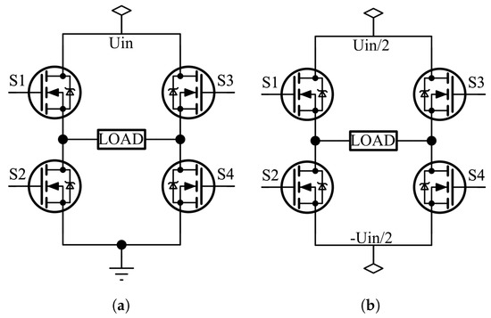
Figure 21.
Full-bridge circuit. (a) Unipolar power supply; (b) bipolar power supply.
It is also possible to use a Marx generator circuit based on avalanche bipolar junction transistors (ABJTs) (see Figure 8), as suggested in [48]. The main disadvantage of this design is that it uses a voltage ramp to trigger the avalanche transistors with a shorted base–emitter junction. Such a design can be highly unreliable. However, this issue can be mitigated by increasing the triggering speed [48]. The primary advantage of this topology is its extremely fast pulse rise time, ranging between 200 and 500 ps.
3.9. High-Voltage OPAMPs
A less common method for generating high-frequency pulses from high voltage is the use of high-voltage power operational amplifiers. The most effective solution is to use power amplifiers from Apex Microtechnology (Tucson, AZ, USA), which offers several products specifically designed for high-voltage applications. These include the PA family (see Table 1).

Table 1.
Comparison of high-voltage power operational amplifiers.
From the comparison of this PA power operational amplifier family, it is clear that most devices are designed for voltages below 1 kV. As a result, if we want to generate high-voltage and high-frequency pulses over 1 kV, we need to use PA89 or PA99. However, the slow slew rates, limited bandwidths, and extremely high costs of these two devices make them impractical for the intended high-frequency high-voltage pulse driver design.
3.10. Control Circuits
Considering all the literature discussed in this comprehensive review, it is also important to mention the basic control methods for the presented architectures. A typical high-voltage, high-frequency pulse generator control circuit may include MCUs, FPGAs, external trigger sources, oscillators, gate drivers, and electrical isolators.
The microcontroller, together with oscillators or external trigger sources, serves as the central timing and control unit of the system. Its primary role is to generate precisely timed control signals that drive the MOSFET switches. The MCU also enables adjustment of pulse parameters such as width, repetition rate, and edge slopes [49].
An FPGA, on the other hand, allows users to configure time sequences, making it possible to rapidly reconfigure multichannel outputs under repetitive discharge conditions. FPGAs excel in timing precision, parallel control, and multichannel scalability, which makes them particularly suitable for complex systems such as pulse-forming networks (PFNs) [50]. However, they are generally more complex to program and typically more expensive than MCU-based solutions.
The control signals generated by the MCU or FPGA are then passed through electrical isolators and gate driver circuits [51,52]. These components provide isolation and amplification, ensuring the signals reach the levels required for reliable MOSFET operation.
In high-voltage systems that use different types of FETs, digital isolators are especially important for safely separating the low-voltage control circuits from the high-voltage power side. Without isolation, noise, interference, or faults from the power side could damage the control electronics or even endanger operators [53]. Digital isolators ensure that the pulse signals driving the FETs are transmitted accurately across the isolation barrier while maintaining system safety.
4. Comparison of High-Voltage High-Frequency Generator Architectures
This section presents a comparison of the previously mentioned high-voltage, high-frequency generator architectures based on a comprehensive literature review. This comparison is provided in Table 2. It clearly illustrates their relative advantages and disadvantages in terms of cost, size, design complexity, and output stability. The parameters in the table, such as cost, size, complexity, and stability, are closely interrelated. Generally, everything depends on the manufacturing complexity. The more components involved, the higher the complexity. Consequently, there is an almost direct correlation with size and price—the more complex the design, the larger and more expensive it is. Stability, in turn, depends both on the quality of the components (the higher the quality, the higher the price) and on the complexity of the system (the more complex and sophisticated the control, the higher the achievable precision). Markings in the table: +—small, ++—medium, +++—high, ++++—extremely high.

Table 2.
Comparison of high-voltage high-frequency generator architectures.
Vacuum tubes and high-voltage operational amplifiers belong to the obsolete or impractical category. Historically, vacuum tubes such as thyratrons, krytrons, and klystrons were widely used because they can withstand extremely high voltages and harsh environments, but they are bulky, costly, and complex to implement. High-voltage OPAMPs, while convenient from a circuit integration perspective, remain prohibitively expensive and suffer from slow slew rates and limited bandwidth, making them unsuitable for nanosecond-scale, MHz-class drivers.
A second category consists of secondary-use architectures. Blumlein structures and pulse-forming networks provide well-shaped, rectangular, or flat-top pulses and are valued for their robustness. However, they lack flexibility in pulse width control and are generally limited in output voltage. Tesla transformers offer high-frequency operation but are sensitive to tuning. Voltage multipliers (Cockcroft–Walton, Karthaus–Fischer, Dickson and hybrid topologies) are simple and cost-effective, particularly for generating tens of kilovolts at moderate frequencies, but suffer from internal voltage drops and increased ripple when scaled to high frequencies. These solutions remain relevant where simplicity, cost, or specialized waveform requirements are more important than overall efficiency or scalability.
The most practical and widely used category today includes solid-state switches, switching-mode power supply-based pulse generators, and modern Marx generators (see Figure 22). Solid-state devices, such as SiC and GaN MOSFETs, enable extremely fast rise and fall times (sub-nanosecond to a few nanoseconds), high repetition rates, and stable high-voltage operation in compact designs. Switching-mode supplies provide modularity, compactness, and precise pulse control, while modern Marx generators, enhanced by SiC and GaN switches, achieve scalable kilovolt outputs with nanosecond transitions and high repetition rates. These architectures are well suited for directly driving capacitive loads like Pockels cells, where both speed and stability are critical.
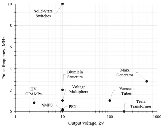
Figure 22.
High-voltage pulse generator architectures comparison.
In practice, state-of-the-art solutions combine the strengths of these topologies. Hybrid designs integrating SiC or GaN solid-state switches with SMPS front ends, Marx generator stages, or voltage multipliers achieve the best trade-off between size, cost, speed, stability, and voltage scalability. Based on this comparison, voltage multipliers, solid-state switch-based circuits, and switching-mode power supply architectures stand out as the most promising candidates for further research in the field of high-performance, high-voltage, and high-frequency generators for Pockels cells.
The potential application areas of high-voltage, high-frequency pulse generators include plasma, biological, and industrial fields. Plasma applications cover electron beam generation, high-density plasma, pulse corona discharge, plasma characterization, dielectric barrier discharge, nonthermal-plasma generation, and plasma synthetic jets. Typical pulse durations range from less than 50 ns to more than 200 ns. The PRF varies from ≤1 kHz up to more than 100 kHz, while the corresponding voltages extend from 2.5 kV to 77 kV. Industrial and other applications include ultrawideband pulses, microwave systems, magnetizing switching experiments, liquid and air purification, ozone production, antennas, and electron guns. Pulse durations range from less than 5 ns to 500 ns. The PRF spans from 10 Hz to 500 MHz, with voltages between −5 kV and 350 kV. Biological applications include electro-manipulation, tumor treatment, cell response, biomedical electroporation, variable biomedical loads, biological studies, gene therapy, and medicine. Pulse durations vary from less than 10 ns to more than 100 ns. The PRF ranges from ≤20 Hz up to 100 MHz, with voltages extending from 0.39 kV to 600 kV [8].
5. Conclusions
A comprehensive review and comparison of high-voltage, high-frequency generator architectures has been carried out. The analysis demonstrated that traditional solutions such as vacuum tubes (up to 100 kV), high-voltage operational amplifiers (up to 2.5 kV), and classic Marx- or Tesla-based designs (up to hundreds of kV) are either obsolete or restricted to specialized applications where specific conditions, such as tolerance or very high voltage without demanding rise-time requirements, are needed. While these approaches remain historically significant, they no longer satisfy the performance, efficiency, and compactness requirements.
Intermediate solutions with output voltages up to 10 kV, including Blumlein structures, pulse-forming networks, and voltage multipliers offer certain advantages in simplicity, cost, or pulse shaping, and may still be applied in cases where fixed-width or flat-top pulses are beneficial. However, they are constrained in flexibility, frequency scalability, and voltage stability, which limits their applicability to future systems.
The most promising directions for further development are found in architectures based on wide-bandgap solid-state devices such as SiC and GaN MOSFETs, switching-mode power supplies, and modern Marx generator topologies where pulse frequencies up to 10 MHz can be achieved. These approaches combine fast rise and fall times in the nanosecond range, repetition rates up to several megahertz, and scalable voltage amplitudes suitable for driving capacitive loads such as Pockels cells. In particular, hybrid solutions that integrate solid-state switching with modular switching-mode power supply stages, voltage multipliers, or compact Marx generators offer the best trade-off between speed, stability, efficiency, and design compactness.
In conclusion, solid-state architectures are leading the way in high-performance 1–10 kV, 0.001–10 MHz pulse generation with their < 1 ns slew rates. These systems are capable of meeting the needs of modern laser and electro-optical applications while providing reliability and scalability (from 1 kV to 10 kV) in the face of ever-increasing demands for speed and efficiency. Therefore, further optimization of the driver circuit should be aimed at increasing efficiency, reducing power losses, and implementing advanced cooling solutions to ensure stable operation at high pulse repetition rates. The correct choice of circuit topology and components will allow us to develop a high-performance Pockels cell driver that meets the necessary requirements for a high-voltage, high-frequency pulse generator.
Author Contributions
Conceptualization, E.A. and V.B.; investigation, E.A.; writing—original draft preparation, E.A. and V.B.; writing—review and editing, E.A. and V.B.; visualization, E.A. All authors have read and agreed to the published version of the manuscript.
Funding
This research received no external funding.
Data Availability Statement
Data is contained within the article.
Conflicts of Interest
The authors declare no conflicts of interest.
Abbreviations
The following abbreviations are used in this manuscript:
| ABJT | Avalanche Bipolar Junction Transistor |
| AC | Alternating Current |
| BJT | Bipolar Junction Transistor |
| BMPG | Boosted Modular Pulse Generator |
| CDVM-A | Capacitor Diode Voltage Multiplier Type A |
| CWVM | Cockcroft–Walton Voltage Multiplier |
| DC | Direct Current |
| DCP | Dickson Charge Pump |
| DVM | Dickson Voltage Multiplier |
| EHD | Electrohydrodynamic |
| FET | Field-Effect Transistor |
| FPGA | Field-Programmable Gate Array |
| GaN | Gallium Nitride |
| HCWDVM | Hybrid Cockcroft–Walton and Dickson Voltage Multiplier |
| HVPG | High-Voltage Pulse Generator |
| IGBT | Insulated-Gate Bipolar Transistor |
| KFVM | Karthaus–Fischer Voltage Multiplier |
| LED | Light-Emitting Diode |
| MCU | Micocontroller Unit |
| MEMS | Microelectromechanical System |
| MOSFET | Metal-Oxide-Semiconductor Field-Effect Transistor |
| OPAMP | Operational Amplifier |
| PA | Power Amplifier |
| PCB | Printed Circuit Board |
| PCM | Phase-Change Material |
| PFL | Pulse-Forming Line |
| PFN | Pulse-Forming Network |
| Si | Silicon |
| SiC | Silicon Carbide |
| SJ | Super Junction |
| SMPS | Switching-Mode Power Supply |
| SPG | Switching Power Generator |
| TCOX | Thick Central Oxide |
| TEC | Thermoelectric Cooling |
| TIM | Thermal Interface Material |
References
- Zhao, Z.; Mernick, K.; Costanzo, M.; Minty, M. An ultrafast laser pulse picker technique for high-average-current high-brightness photoinjectors. Nucl. Instruments Methods Phys. Res. Sect. A Accel. Spectrometers Detect. Assoc. Equip. 2020, 959, 163586. [Google Scholar] [CrossRef]
- MEETOPTICS|Search & Compare Quality Optics. 2025. Available online: https://www.meetoptics.com/electro-optics-and-electronics/electro-optics/pockels-cells?categories__t_s=Electro-Optics%20%26%20Electronics%3E%3E%3EElectro-Optics%3E%3E%3EPockels%20Cell&suggestion=Pockels%20Cell (accessed on 26 August 2025).
- Mittal, S.; Arvind, K.; Laxmiprasad, A.S.; Pruthvi, S.S. Design and Development of Pockels Cell Driver for Q Switch LASER in Space Applications. IETE J. Res. 2017, 63, 694–699. [Google Scholar] [CrossRef]
- Kim, H.S.; Yu, C.H.; Jang, S.R.; Kim, G.H. Solid-State Pulsed Power Modulator with Fast Rising/Falling Time and High Repetition Rate for Pockels Cell Drivers. IEEE Trans. Ind. Electron. 2019, 66, 4334–4343. [Google Scholar] [CrossRef]
- Zhuge, Y.; Liang, J.; Fu, M.; Long, T.; Wang, H. Comprehensive Overview of Power Electronics Intensive Solutions for High-Voltage Pulse Generators. IEEE Open J. Power Electron. 2024, 5, 21–40. [Google Scholar] [CrossRef]
- Wang, J.; Zhou, X.; Li, J.; Zhao, T.; Huang, A.Q.; Callanan, R.; Husna, F.; Agarwal, A. 10-kV SiC MOSFET-Based Boost Converter. IEEE Trans. Ind. Appl. 2009, 45, 2056–2063. [Google Scholar] [CrossRef]
- Pachowicz, K. High-Voltage Power Supply for High Repetitive Rate Marx Generator with Quasi-Resonant Zero-Current Switching Transistor Control Algorithm. Energies 2022, 15, 6902. [Google Scholar] [CrossRef]
- Ranjan, A.; Abhishek, A.; Kumar, N.; Verma, B.K. Review of Nanosecond Pulse Generator with High-Power Switching Devices. IEEE Trans. Electron Devices 2024, 71, 5165–5176. [Google Scholar] [CrossRef]
- Neumannn, R.; Stehr, U.; Hein, M.A. High-Voltage Driver Circuits for Electro-Optical RF Modulators. In Proceedings of the International Conference on Electromagnetics in Advanced Applications, ICEAA, Lisbon, Portugal, 2–6 September 2024; Institute of Electrical and Electronics Engineers Inc.: Piscataway, NJ, USA, 2024; pp. 533–538. [Google Scholar] [CrossRef]
- Mohseni, P.; Husev, O.; Vinnikov, D. Thermal Management Experience in GaN-Based DC-DC Converter. In Proceedings of the CPE-POWERENG 2024—18th International Conference on Compatibility, Power Electronics and Power Engineering, Proceedings, Gdynia, Poland, 24–26 June 2024. [Google Scholar] [CrossRef]
- Wang, Y.; Ren, L.; Yang, Z.; Shen, S.; Deng, Z.; Yuan, Q.; Ding, W.; Ding, Z. Heat management technology for solid-state high voltage and high repetitive pulse generators: Towards better effects and reliability. High Volt. 2024, 9, 2–21. [Google Scholar] [CrossRef]
- Singamneni, S.; Badcock, R.; Lumsden, G.; Sengkwon, J.; Caughley, A.; Thrimawithana, D.; Tissink, S.; Behera, M.P.; Lv, Y.; Wadsworth, A.; et al. Design for Additive Manufacturing and Thermal Management in GaN-Based Power Electronics Systems. In Proceedings of the IEEE Southern Power Electronics Conference, SPEC, Brisbane, Australia, 2–5 December 2024. [Google Scholar] [CrossRef]
- Pal, D.; Severson, M. Thermal Interface Materials for Power Electronics Application. In Proceedings of the 2025 41st Semiconductor Thermal Measurement, Modeling & Management Symposium (SEMI-THERM), San Jose, CA, USA, 10–14 March 2025. [Google Scholar]
- Zhang, X.; Iosifidis, N.; Wu, Y.; Wan, H.; Wei, J.; Liu, L.; Wang, X.; Li, W.; Wu, K.; Li, J.; et al. A Comparative Study of Thermal Management Strategies for Overcurrent in Aircraft Power Electronics Applications. IEEE J. Emerg. Sel. Top. Power Electron. 2025, 13, 4488–4503. [Google Scholar] [CrossRef]
- Poggi, T. Algorithms for the implementation of a low level RF control system for a klystron amplifier. Nucl. Instruments Methods Phys. Res. Sect. A Accel. Spectrometers Detect. Assoc. Equip. 2013, 729, 506–516. [Google Scholar] [CrossRef]
- Wen, C.K.; Joshi, S.A.; Chen, S.C.; Tsai, C.J.; Chan, S.Y.; Sun, H.; Chiu, T.W. Copper nitride films with high p-type conductivity fabricated by incorporating middle-frequency pulse into high power impulse magnetron sputtering. Ceram. Int. 2025, 51, 22793–22802. [Google Scholar] [CrossRef]
- Hu, B.; Li, H.; Li, T.; Wang, H.; Zhou, Y.; Zhao, X.; Hu, X.; Du, X.; Zhao, Y.; Li, X.; et al. A long-distance high-power microwave wireless power transmission system based on asymmetrical resonant magnetron and cyclotron-wave rectifier. Energy Rep. 2021, 7, 1154–1161. [Google Scholar] [CrossRef]
- Wu, Y.; Liu, W.; Chen, J.; Sun, X.; Zhang, T. A Novel PWM Signal-Generation Strategy for Pockels Cell Drivers. Photonics 2023, 10, 866. [Google Scholar] [CrossRef]
- Xu, Y.; Chen, W.; Liang, H.; Li, Y.H.; Liang, F.T.; Shen, Q.; Liao, S.K.; Peng, C.Z. Megahertz high voltage pulse generator suitable for capacitive load. AIP Adv. 2017, 7, 115210. [Google Scholar] [CrossRef]
- Nakashima, D.; Kino, Y.; Eguchi, K. Design of a bipolar Dickson voltage multiplier suitable for low output voltage conditions to provide efficient food processing. Energy Rep. 2023, 9, 207–213. [Google Scholar] [CrossRef]
- Ahmed, N.; Khan, N.; Abbas, T. An Inverter-Fed Cockcroft-Walton Multiplier Based High Voltage DC Source for Tokamak. In Proceedings of the 2022 International Conference on Emerging Trends in Electrical, Control, and Telecommunication Engineering, ETECTE 2022—Proceedings, Lahore, Pakistan, 2–4 December 2022; Institute of Electrical and Electronics Engineers Inc.: Piscataway, NJ, USA, 2022. [Google Scholar] [CrossRef]
- Ballo, A.; Grasso, A.D.; Palumbo, G. Comparison of the Wide-Frequency Range Dynamic Behavior of the Dickson and Cockcroft-Walton Voltage Multipliers. In Proceedings of the 2021 IEEE International Midwest Symposium on Circuits and Systems (MWSCAS), Lansing, MI, USA, 9–11 August 2021; pp. 348–351. [Google Scholar] [CrossRef]
- Ma, J.; Yu, L.; Ren, L.; Liao, Y.; Dong, S.; Yao, C. High Voltage Nanosecond Pulse Generator based on Inductive Energy Storage with Adjustable Pulse Width. In Proceedings of the 2022 IEEE International Conference on High Voltage Engineering and Applications, ICHVE 2022, Chongqing, China, 25–29 September 2022; Institute of Electrical and Electronics Engineers Inc.: Piscataway, NJ, USA, 2022. [Google Scholar] [CrossRef]
- Ma, J.; Ren, L.; Yu, L.; Yao, C.; Dong, S. 10.7kV nanosecond pulse generator based on pulse forming line and variable impedance transmission line transformer. In Proceedings of the 2023 IEEE Pulsed Power Conference (PPC), San Antonio, TX, USA, 25–29 June 2023. [Google Scholar] [CrossRef]
- Zhong, Z.; Rao, J.; Liu, H.; Redondo, L.M. Review on Solid-State-Based Marx Generators. IEEE Trans. Plasma Sci. 2021, 49, 3625–3643. [Google Scholar] [CrossRef]
- Wu, F.; Yao, C.; Chen, Y.; Yu, L.; Dong, S.; Wang, H. All-Solid-State Ultrashort Pulse Generator by Capacitive Chopping Circuit. IEEE Trans. Power Electron. 2023, 38, 9897–9906. [Google Scholar] [CrossRef]
- Jeong, W.C.; Lee, J.Y.; Choi, M.K.; Ryoo, H.J. Implementation of the 160kV High Voltage DC/DC Converter. In Proceedings of the ICPE 2023-ECCE Asia—11th International Conference on Power Electronics—ECCE Asia: Green World with Power Electronics, Jeju Island, Republic of Korea, 22–25 May 2023; pp. 2867–2872. [Google Scholar] [CrossRef]
- Jin, Y.; Cheng, L. An Inductive Isolation-Based 10 kV Modular Solid Boost-Marx Pulse Generator. Electronics 2023, 12, 1586. [Google Scholar] [CrossRef]
- Zeng, W.; Yao, C.; Dong, S.; Wang, Y.; Ma, J.; He, Y.; Yu, L. Self-Triggering High-Frequency Nanosecond Pulse Generator. IEEE Trans. Power Electron. 2020, 35, 8002–8012. [Google Scholar] [CrossRef]
- He, Y.; You, X.; Ma, J.; Yu, L.; Zeng, W.; Dong, S.; Zhang, Z.; Yao, C. A Polarity-Adjustable Nanosecond Pulse Generator Suitable for High Impedance Load. IEEE Trans. Plasma Sci. 2020, 48, 3409–3417. [Google Scholar] [CrossRef]
- Chen, Y.; Meng, Y.; Xie, Y. Investigation of Output Influencing Factors in Coaxial Blumlein Rectangular Pulse Generator. IEEE Trans. Plasma Sci. 2025, 53, 398–404. [Google Scholar] [CrossRef]
- Yang, S.; Yu, R.; Sun, J.; Sun, Y.; Chen, R.; Gao, J. Study on a Coaxial Stacked Blumlein Pulse Generator With Inner Conductors Connected in Parallel. IEEE Trans. Plasma Sci. 2024, 52, 5241–5248. [Google Scholar] [CrossRef]
- Ma, J.; Yu, L.; Ren, L.; Yao, C.; Dong, S.; Ma, J.; Xu, W. Nanosecond Pulse Generator Based on Inductive Energy Storage Forming Line with Impedance Matching Modulation Capability. IEEE Trans. Ind. Electron. 2024, 71, 15643–15653. [Google Scholar] [CrossRef]
- Kermadi, M.; Hossain, Z.; Mekhilef, S.; Mubin, M.; Mokhlis, H. A Half-bridge Evaluation Board for Prototyping Power Converters using Sillicon Carbide (SiC) Switching Devices. In Proceedings of the 4th International Conference on Smart Grid and Renewable Energy, SGRE 2024—Proceedings, Doha, Qatar, 8–10 January 2024; Institute of Electrical and Electronics Engineers Inc.: Piscataway, NJ, USA, 2024. [Google Scholar] [CrossRef]
- Barbosa, F.; Arnold, P.A.; Mchale, G.B.; James, G.; Brown, G.; Cook, E.G.; Hickman, B.C. Development of Solid-State Drivers for the NIF Plasma Electrode Pockels Cell. In Proceedings of the 2008 IEEE International Power Modulators and High-Voltage Conference, Las Vegas, NV, USA, 27–31 May 2008. [Google Scholar]
- Trivedi, S.S.; Sant, A.V. Comparative analysis of dual active bridge dc–dc converter employing Si, SiC and GaN MOSFETs for G2V and V2G operation. Energy Rep. 2022, 8, 1011–1019. [Google Scholar] [CrossRef]
- Glashauser, M.; Kreutzer, O. Why Are Conventional Si MOSFETs Better Than SiC and GaN in Low Power Applications? In Proceedings of the WiPDA Asia 2023—IEEE Workshop on Wide Bandgap Power Devices and Applications in Asia, Hsinchu, Taiwan, 27–29 August 2023. [CrossRef]
- Siemieniec, R.; Wattenberg, M.; Kocaaga, E.; Jagannath, S.; Kahrimanovic, E.; Bhandari, J.; Shim, H.; Pignatelli, A. 400V SiC MOSFET empowering three-level topologies for highly efficient applications from motor-drives to AI. Power Electron. Devices Components 2025, 12, 100104. [Google Scholar] [CrossRef]
- Huang, Z.H.; Tang, S.W.; Fan, C.T.; Lin, M.C.; Wu, T.L. Dynamic on-resistance stability of SiC and GaN power devices during high-frequency (100–300 kHz) hard switching and zero voltage switching operations. Microelectron. Reliab. 2023, 145, 114983. [Google Scholar] [CrossRef]
- Wang, T.; Zhong, Y.; Luo, L.; Zeng, F.; Zhao, Z.; Cui, Y.; Xu, M.; Xu, X.; Linewih, H.; Han, J. Temperature dependence of dynamic performance of SiC MOSFETs in a half-bridge configuration. Microelectron. J. 2025, 160, 106672. [Google Scholar] [CrossRef]
- Chen, Y.; Du, J.; Feng, L.; Xiao, J.; Zhang, J.; He, Y. Comparative Study on Driving Switching Characteristics of GaN-FET and SiC-MOSFET in Transient High Voltage Pulse Discharge Circuit. In Proceedings of the 7th IEEE International Conference on High Voltage Engineering and Application, ICHVE 2020—Proceedings, Beijing, China, 6–10 September 2020. [Google Scholar] [CrossRef]
- Cheng, J.; Zhang, Y.; Cheng, X.; Guo, K.; Wang, Y.; Jiang, M.; Wang, Y.; Liu, Y. Thermal behavior and switching losses of MOSFET in high-frequency transformer circuits. Case Stud. Therm. Eng. 2025, 73, 106643. [Google Scholar] [CrossRef]
- Han, L.; Liang, L.; Wang, Y.; Tang, X.; Bai, S. Performance limits of high voltage press-pack SiC IGBT and SiC MOSFET devices. Power Electron. Devices Components 2022, 3, 100019. [Google Scholar] [CrossRef]
- Qing, Z.; Liang, L.; Liu, T. Transient turn-on characteristics of Si RBDT and SiC MOSFET under nanosecond current pulse range. Solid-State Electron. 2024, 217, 108953. [Google Scholar] [CrossRef]
- Zhang, J.; Jiang, Y.; Huang, H.; Zhang, Z.; Cheng, J.; Yi, B.; Yang, H.; Wang, Z. Superjunction SiC TCOX-MOSFET: Study and Comparison. In Proceedings of the 2022 IEEE 16th International Conference on Solid-State and Integrated Circuit Technology, ICSICT 2022, Nangjing, China, 25–28 October 2022. [Google Scholar] [CrossRef]
- Yu, L.; Sun, W.; Yao, C.; Dong, S.; Li, K.; He, D.; Jin, Y.; Bo, Z. A Novel Boost Marx Pulse Generator Based on Single-Driver Series-Connected SiC MOSFETs. IEEE Trans. Ind. Electron. 2024, 71, 2070–2079. [Google Scholar] [CrossRef]
- Feizi, M.; Vermulst, B. A modular high-voltage pulse generator based on transformer charging with high boosting capability and low-voltage dc input. In Proceedings of the 2023 11th International Conference on Power Electronics and ECCE Asia (ICPE 2023—ECCE Asia), Jeju Island, Republic of Korea, 22–25 May 2023. [Google Scholar]
- Wen, K.; Liang, L.; Yan, X.; Zhang, Z. Avalanche Transistor-Based Marx Generator Provides 1.15-kV/1-MHz Sub-Nanosecond Pulses Due to Triggering Acceleration. IEEE Trans. Plasma Sci. 2024, 52, 2898–2906. [Google Scholar] [CrossRef]
- Zhang, Y.; Ouyang, C.; Wang, Q.; Gao, J.; Zhao, Y.; Ren, X.; Liu, L.; Zhou, Z. A High-Speed High-Voltage Pulse Generator With Adjustable Falling Slope Based on Programable Multi Narrow Pulses Drive Method for Series MOSFETs. IEEE Trans. Power Electron. 2025, 40, 1645–1653. [Google Scholar] [CrossRef]
- Pan, W.; Lv, H.; Liu, K.; Fu, R.; Liu, W.; Huo, Y.; Sun, Y. Design of Multi-channel Pulse Signal Generator with Adjustable Time Sequence. In Proceedings of the 2024 10th Euro-Asian Pulsed Power Conference, 25th International Conference on High-Power Particle Beams and 20th International Symposium on Electromagnetic Launch Technology (EAPPC/BEAMS/EML), Amsterdam, The Netherlands, 22–26 September 2024. [Google Scholar]
- Shu, J.; Sun, J.; Wu, X.; Chen, K.J. A Dynamic Two-Stage Gate Driver for Unlocking the Fast-Switching Potential of GaN HEMT. IEEE Trans. Power Electron. 2025, 40, 4752–4756. [Google Scholar] [CrossRef]
- Ghafoor, S.; Kulkarni, M.; Mirzadarani, R.; Vaessen, P.; Niasar, M.G. A Scalable Isolated Gate Driver With Programmable Frequency and Duty Cycle for Series-Connected SiC MOSFETs. IEEE Open J. Ind. Electron. Soc. 2025, 6, 95–114. [Google Scholar] [CrossRef]
- Ke, J.; Feng, J.; Liu, C.; Guan, Z.; Xu, H.; Zhao, M. Digital Isolator Based on On-Chip Transformer for High-Voltage SiC MOSFET. In Proceedings of the 2023 IEEE 7th Conference on Energy Internet and Energy System Integration, EI2 2023, Hangzhou, China, 15–18 December 2023; pp. 3917–3923. [Google Scholar] [CrossRef]
Disclaimer/Publisher’s Note: The statements, opinions and data contained in all publications are solely those of the individual author(s) and contributor(s) and not of MDPI and/or the editor(s). MDPI and/or the editor(s) disclaim responsibility for any injury to people or property resulting from any ideas, methods, instructions or products referred to in the content. |
© 2025 by the authors. Licensee MDPI, Basel, Switzerland. This article is an open access article distributed under the terms and conditions of the Creative Commons Attribution (CC BY) license (https://creativecommons.org/licenses/by/4.0/).