1. Introduction
In winter, the high-density polyethylene (HDPE) sheath of stay cables is susceptible to freezing [
1,
2]. As temperatures rise, ice shedding may occur from the surface of stay cable sheaths, posing significant impact hazards to pedestrians and vehicles below, resulting in safety incidents and traffic disruptions [
3,
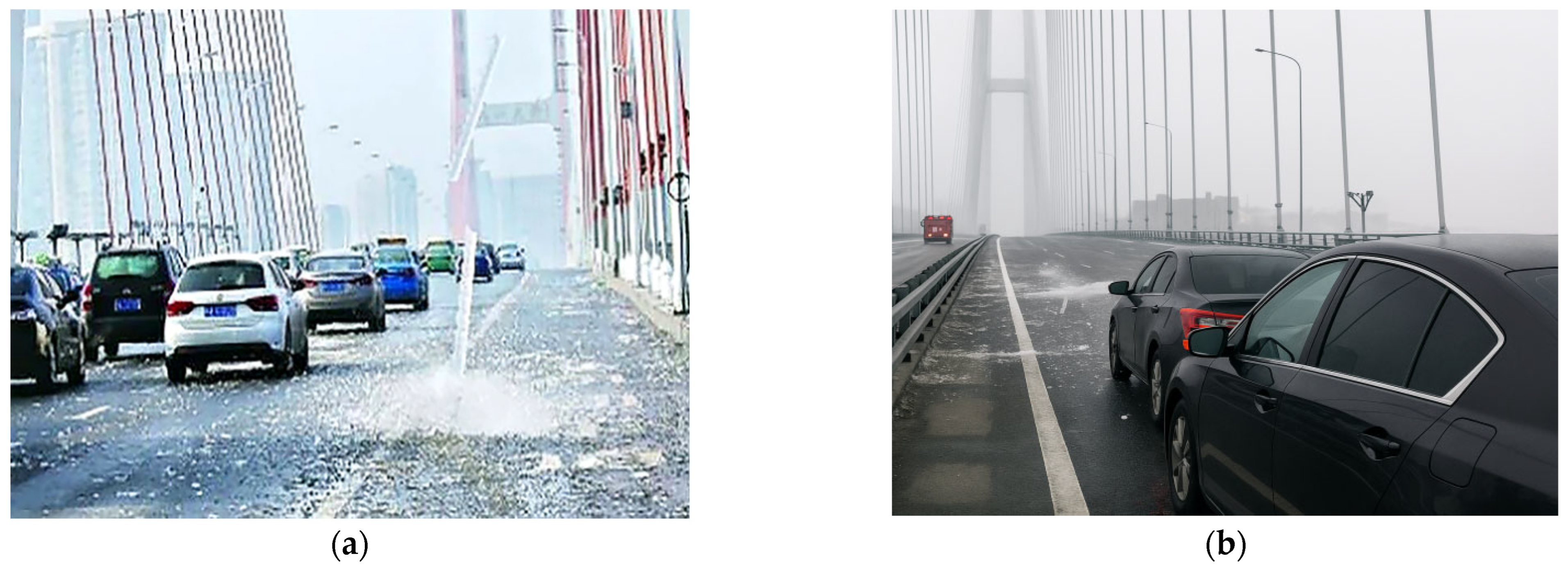
4]. For instance, in both 2019 and 2024, ice shedding from the stay cables of the Wuhan Erqi Yangtze River Bridge resulted in vehicle damage and significant traffic congestion [
5]. The phenomenon of ice shedding from stay cable sheaths is depicted in
Figure 1. Additionally, when ice remains attached to the stay cables, they become more vulnerable to aerodynamic forces and wind-induced vibrations [
6], which, in extreme cases, could cause the structural integrity of the bridge to be compromised. Consequently, timely and effective de-icing measures are considered crucial for ensuring bridge traffic safety and for the protection of lives and property during winter.
At present, the main de-icing methods include artificial, chemical methods, and laying carbon fiber heating cables [
7,
8,
9,
10]. Although these methods have been implemented in specific scenarios, their effectiveness is often limited by low efficiency, safety concerns, and high costs, making them insufficient to meet current demands [
11]. As a result, de-icing robots have been developed as a more efficient, safer, and cost-effective alternative for stay cable sheaths de-icing.
While the efficiency of ice removal is being improved, the sheath of stay cables must be protected from damage caused by de-icing robots. Consequently, the complete removal of all ice accumulation cannot be achieved, and residual ice may remain on the cable surface after de-icing [
12]. When the robot continues to climb after the de-icing process, these residuals can significantly reduce the friction coefficient between the robot and the stay cable sheaths, potentially leading to slippage or even falling due to insufficient traction. Therefore, reliable climbing capability is considered a core requirement for the proper functioning of stay cable de-icing robots. The rationality of the climbing mechanism’s design is regarded as a key factor in determining the robot’s operational efficiency and safety under complex conditions. In this paper, design rationality refers to the adequacy of component sizing and parameter choices (clamping, traction, torque, speed) to meet stability targets under thin-ice, high-inclination, and elevated-load conditions. The cable-climbing mechanism is regarded as the core subsystem of stay cable de-icing robots, with its structural rationality directly affecting the operational reliability, efficiency, and safety of the robot under complex conditions. In recent years, numerous robotic solutions have been proposed by researchers worldwide to meet the repair and inspection demands of high-altitude stay cable structures, snow removal of stay cables and de-icing of power transmission lines.
The design of robots for power transmission lines is dictated by the requirement to operate on slender, elevated, and electrically energized conductors spanning long distances. The foremost design priorities are established as electrical insulation, operational safety, minimal weight to avoid increasing line loads, and reliable obstacle-crossing capability. Consequently, the focus in typical solutions is placed on dynamic balancing and obstacle-surmounting mechanisms. These designs are commonly validated through multibody dynamic simulations and field tests. For example, a climbing robot integrating an obstacle-surmounting mechanism with a dynamic balancing system was proposed by Xiang Yue et al., and Hao et al. [
13,
14] whose motion stability was verified through both ADAMS based simulations and field experiments.
However, the stay cables of cable-stayed bridges are characterized by large diameters, steep inclinations, and outer sheaths made of smooth high-density polyethylene. These conditions impose three primary technical requirements on robotic design: first, sufficient attachment capacity with a prudent clamping margin must be ensured; second, traction and clamping stability must be ensured under conditions of both low surface friction and high operational load; and third, adequate payload capability is required to carry and operate on-cable tools for tasks such as inspection, repair, snow removal, or de-icing. For instance, an adaptive variable-diameter robot that integrated snow removal and real-time monitoring capabilities was developed by Kim et al. [
15] the stable climbing and effective snow-clearing performance of this robot were subsequently demonstrated through laboratory and field tests. Furthermore, stay cable inspection robots were designed by Wang et al., and Cho et al. [
16,
17] whose climbing mechanisms were experimentally tested to validate their stability and feasibility. Xu et al. [
18] conducted wind-load-equivalent vibration tests on full-scale cable models to evaluate the climbing performance and safety of such robots. Stable operation under Grade 7 wind conditions was successfully verified. Additionally, a climbing robot for cable repair was developed by Zheng et al. and Xu et al. and Kong et al. [
19,
20,
21] and its performance was validated through dynamic modeling and field tests on actual bridge structures.
Although substantial progress has been achieved under normal conditions, climbing stability remains a prominent challenge when covered thin ice is present on the surface of stay cables. Under such circumstances, the coefficient of friction between the climbing mechanism and the cable sheath decreases markedly and becomes spatially non-uniform. This effect is particularly pronounced when mechanical de-icing leaves an uneven distribution of residual ice. These conditions trigger intermittent transitions between static and kinetic friction, as well as a localized loss of traction. Consequently, at steep inclination angles, the risk of backward slip or yaw is significantly elevated. Patchy icing further interrupts continuous contact between the drive module and the stay cables, thereby weakening closed-loop control of traction and clamping forces. Therefore, parameters that guarantee stability on dry surfaces do not guarantee it under thin-ice conditions. It follows that, under the combined operating conditions of low friction, high inclination, and high load, climbing stability on stay cables remains a key issue that warrants further investigation.
To achieve stable climbing on stay cables under thin ice conditions, this paper evaluates the rationality of a dedicated climbing mechanism designed for low-friction, high-inclination, and high-load conditions. Goal: evaluate design rationality and explore the regular trends of motion parameters. Tasks: (1) establish performance criteria for attachment capacity, clamping stability, and payload capability; (2) test the physical prototype to measure key motion parameters under thin-ice conditions and verify stability; (3) conduct a parametric analysis of key structural and control parameters using a virtual prototype. Methods: integrate mechanical theory, climbing experiments, and multibody dynamic simulation in Adams, and assess model–test consistency using relative root mean square error and speed-fluctuation metrics. Results: report stability outcomes and operating margins that provide preliminary validation of the mechanism’s design rationality, quantify friction coefficient and payload boundaries relevant to de-icing operations; and identify regular trends in key motion parameters to enable reliable climbing on low-friction, steeply inclined stay cables. Unlike prior work centered on dry surfaces or power-transmission lines, this study targets stay-cable sheaths under thin ice: we experimentally measured the friction coefficient of the thin-ice–covered sheath–contact interface and validated dynamics (ADAMS) against laboratory climbing tests under μ down to 0.12, 90° inclination, and 12 kg load. This context-specific evidence yields direct design checks (torque/clamping margins, friction/payload limits) and an operational rule (the upper critical clamping force peaks near ~70°; therefore, verify extra clamping margin there and schedule tool deployment away from the peak), providing a practical envelope for component sizing, control set-points, and deployment planning of stay-cable de-icing robots in winter. The structure of this paper is as follows:
Section 2 introduces the structural composition and working principles of the cable-climbing mechanism.
Section 3 provides a theoretical mechanical analysis and discusses the selection of key components.
Section 4 describes the experimental measurements of friction coefficients and climbing velocities under different load conditions.
Section 5 outlines a virtual prototype that was built using ADAMS software, and its accuracy was validated through comparison with experimental data.
Section 6 investigates the variation patterns of critical parameters under various conditions through virtual prototype simulations.
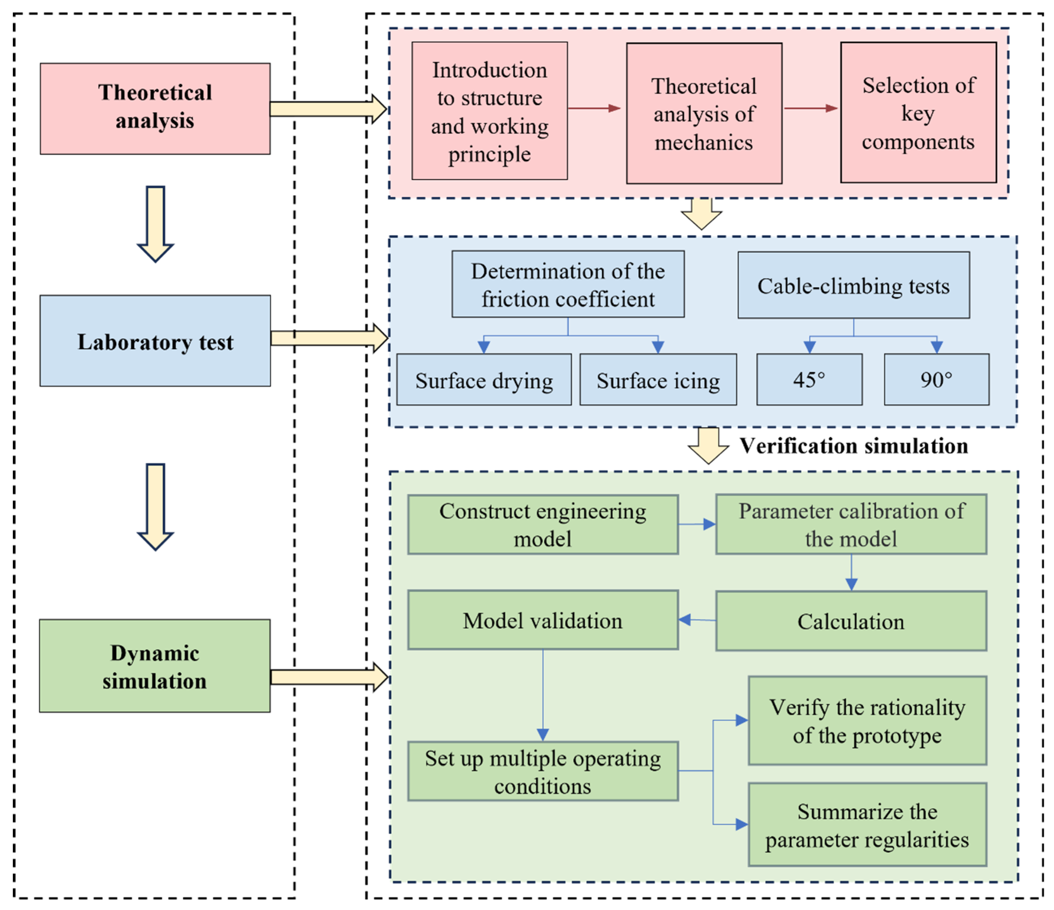
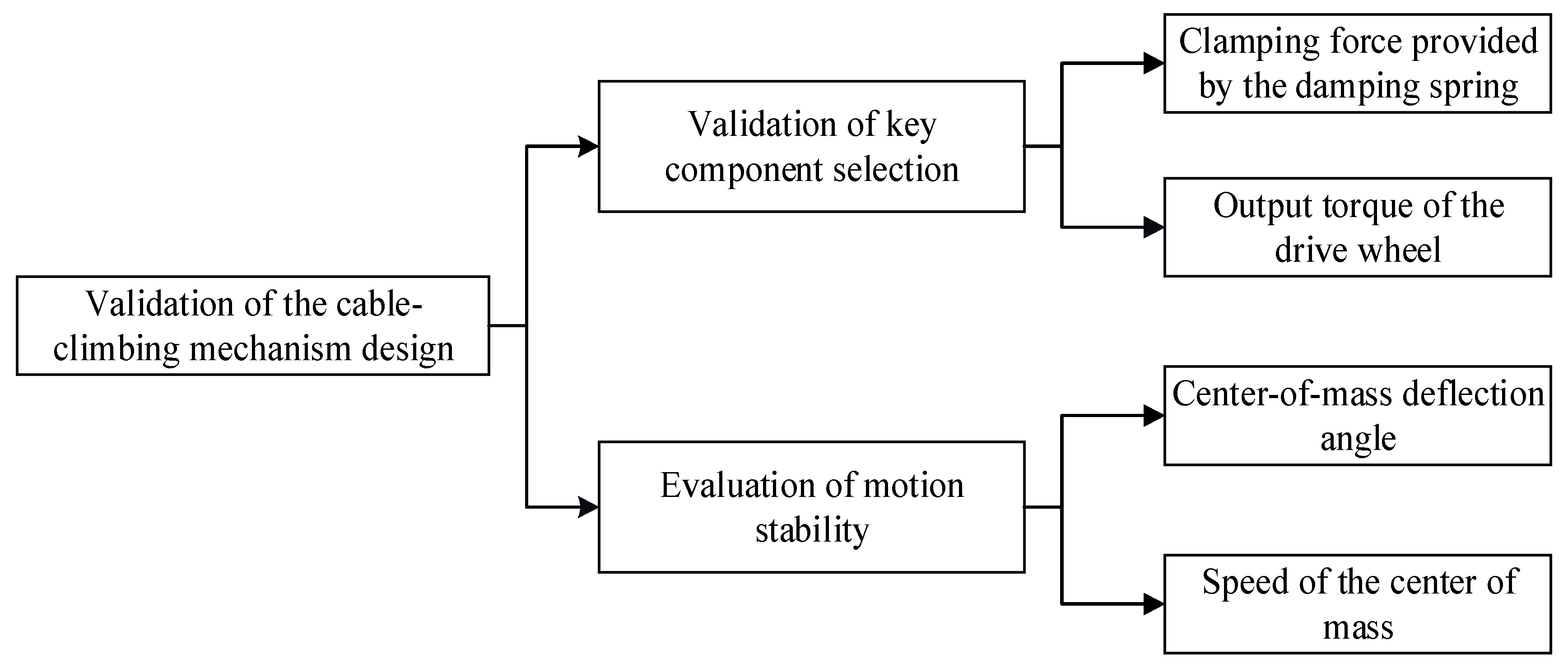
Section 7 summarizes the key findings and proposes future research directions. The complete research workflow is illustrated in
Figure 2.
4. Laboratory Test
The performance of the climbing mechanism on stay cable surfaces covered with thin ice was systematically evaluated through two complementary test procedures: (1) quantitative characterization of interfacial friction properties between the rubber track and ice surface, and (2) measuring the climbing speed of the climbing mechanism under varying load conditions. A physical prototype was fabricated, and a climbing tests platform was established in a step-in constant humidity laboratory. To replicate field conditions of stay cables, climbing tests were conducted on ice-covered stay cable sheaths at inclination angles of 45° and 90°.
4.1. Materials and Equipment
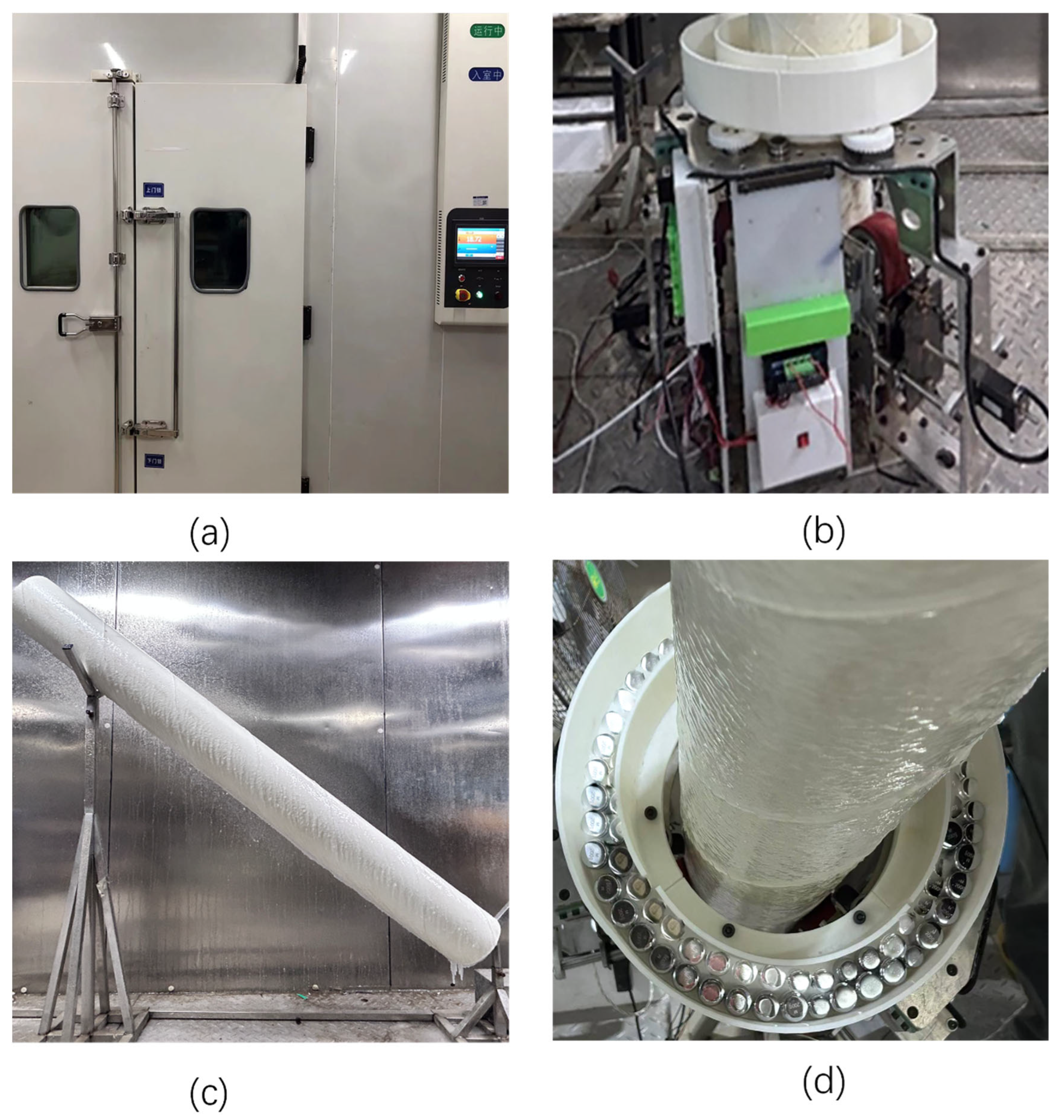
The test was conducted in a step-in constant humidity laboratory (
Figure 6a), with the environmental temperature set to −10 °C ± 0.5 °C. The test focuses on a self-manufactured prototype of a stay cable climbing mechanism (
Figure 6b), which was mounted on a 2 m stay cable sheath with a diameter of 200 mm. To replicate extreme environmental conditions, a spraying system was employed to form a 2 mm-thick layer of thin ice on the surface of the stay cable sheath (
Figure 6c). To replicate various load conditions, standard weights were evenly distributed on the upper platform (
Figure 6d).
Notably, laboratory tests were performed under controlled thin-ice conditions without wind loading, freeze–thaw cycling, or deliberately patterned irregular ice. This setup isolates low-friction climbing behavior and enables repeatable measurement of traction, clamping margin, and stability of climbing speed, but does not replicate in-service environmental variability.
The testing data collection consisted of two key components:
- (1)
Friction coefficient determination: The deformation of the spring was measured using a vernier caliper with an accuracy of 0.01 mm. Based on Hooke’s law and the established mechanical model, the equivalent friction coefficient between the climbing mechanism and the surface of the stay cable sheath was calculated.
- (2)
Speed measurement: the climbing mechanism’s speed is measured using an encoder integrated into the drive system.
4.2. Determination of the Friction Coefficient
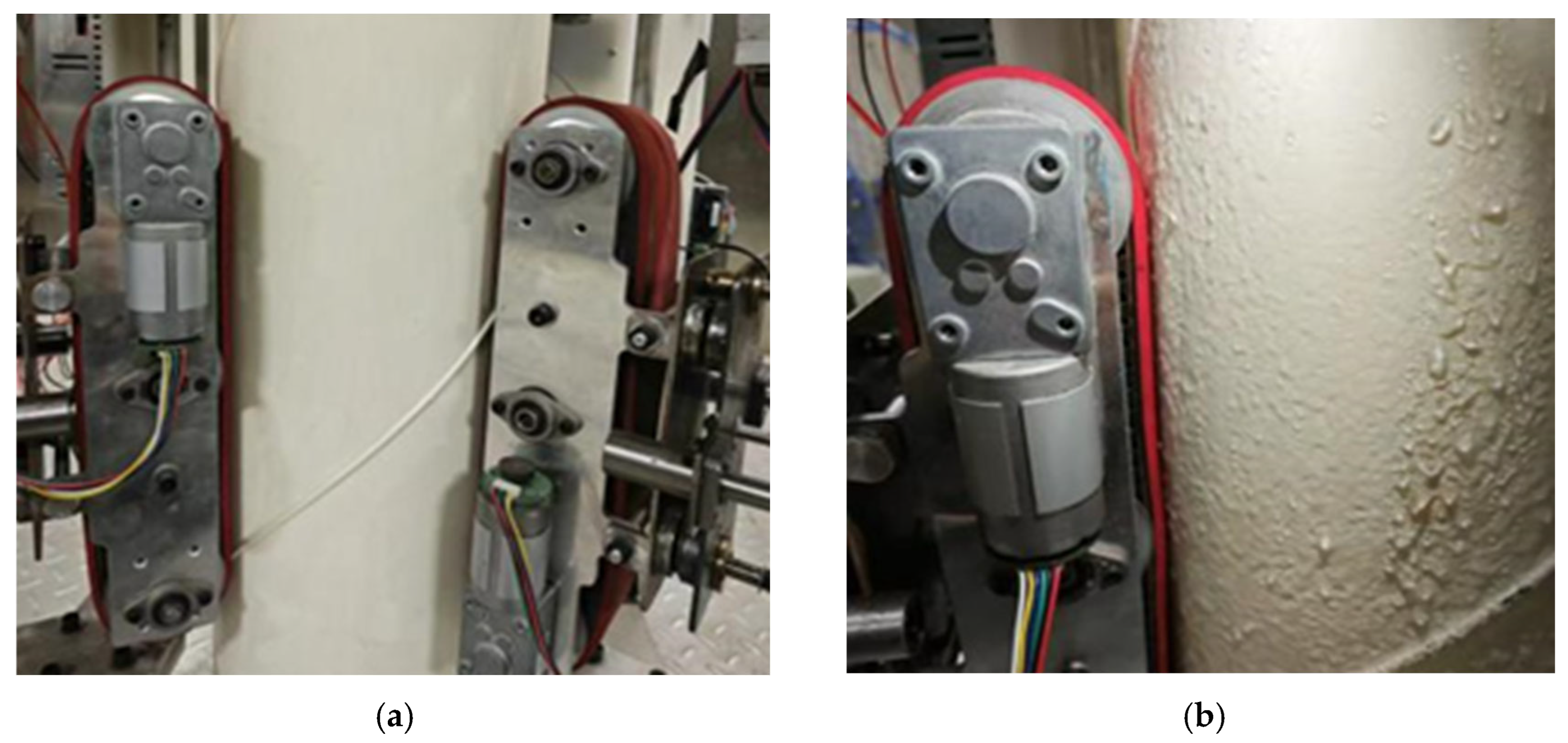
The friction coefficient between the climbing mechanism and the stay cable sheath surface was determined through tests conducted under two representative operational conditions: dry and covered with thin ice. The physical prototype was initially mounted onto the stay cable sheath (
Figure 7), and the spring preload was gradually increased via stepper motor-driven lead screw control until the mechanism approached its critical sliding threshold. Each condition was tested in triplicate, and the mean spring compression displacement was recorded. The corresponding critical clamping force was then determined based on Hooke’s law. Subsequently, the equivalent friction coefficient
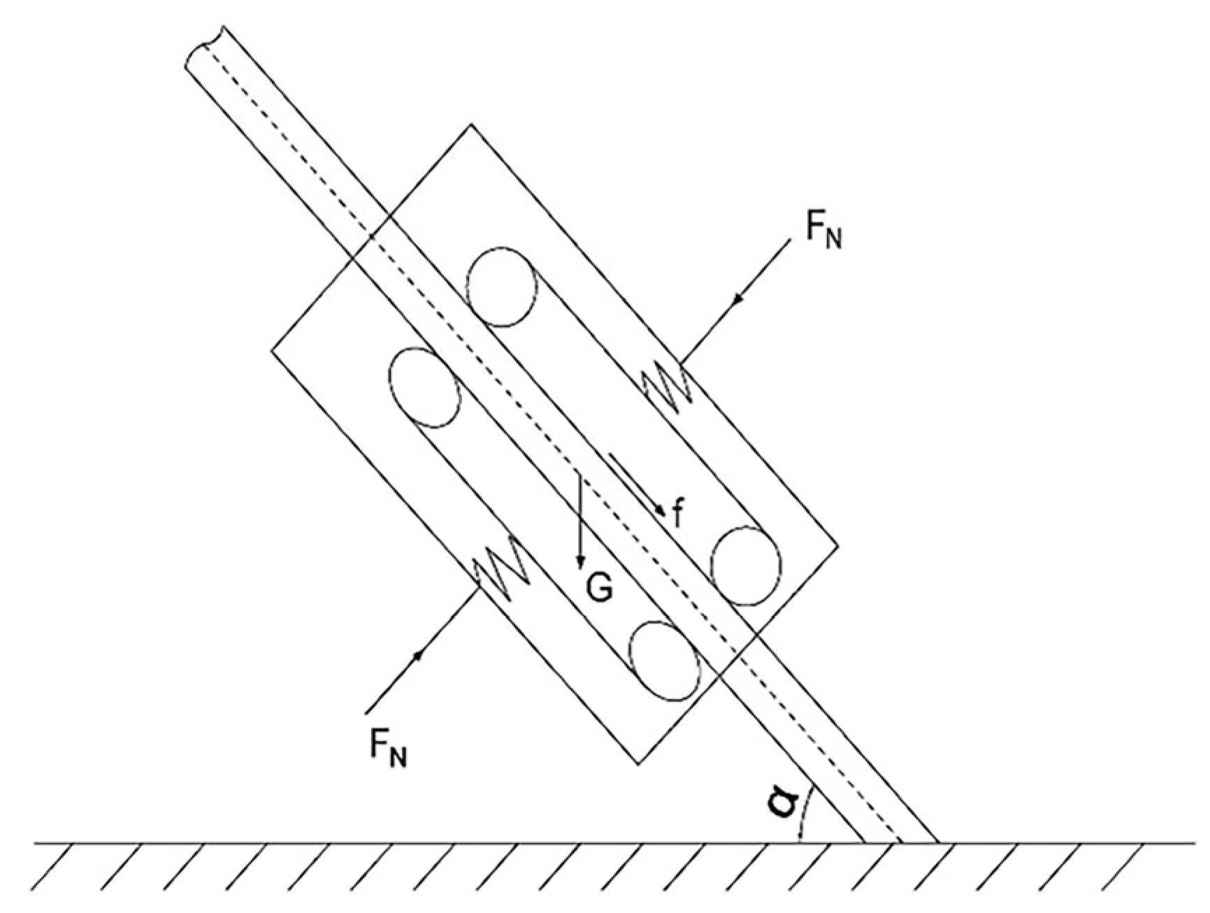
μ was derived from the mechanical model described in
Section 2. The calculated results are presented in
Table 3.
Application of the present icing protocol yielded a mean friction coefficient of μ = 0.15 on the iced sheath, with a range of 0.12–0.20 observed across repeated tests owing to spatial non-uniformity and thin meltwater films.
Table 3 lists the representative mean (μ ≈ 0.15), and the dynamic simulations therefore adopt μ ∈ [0.12, 0.20].
4.3. Climbing Tests
The climbing speed of the cable-climbing mechanism is a key indicator of its operational performance, as it directly affects the efficiency of engineering applications. Different combinations of inclination angle and applied load are listed as climbing test conditions in
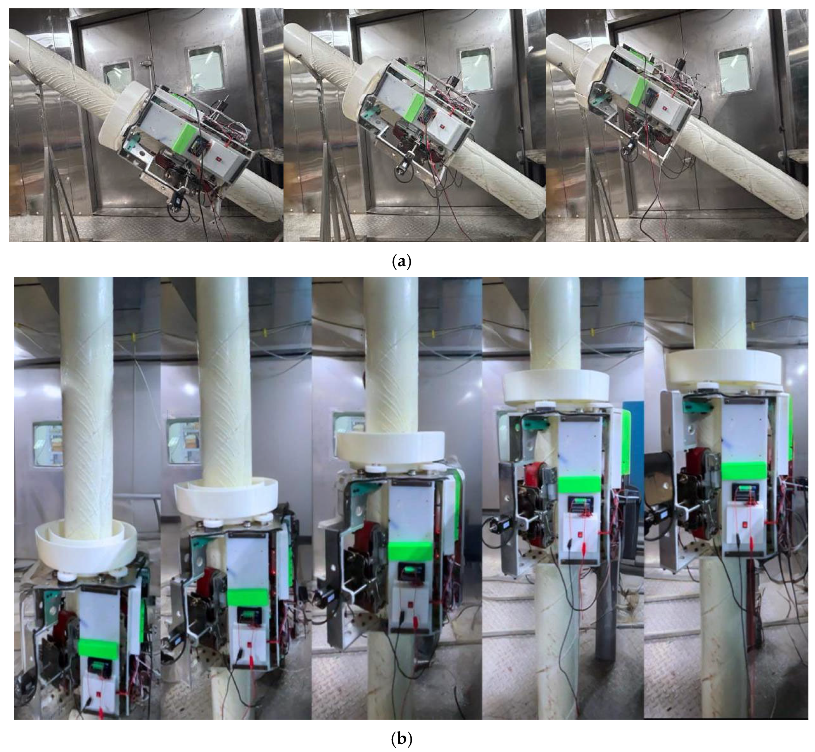
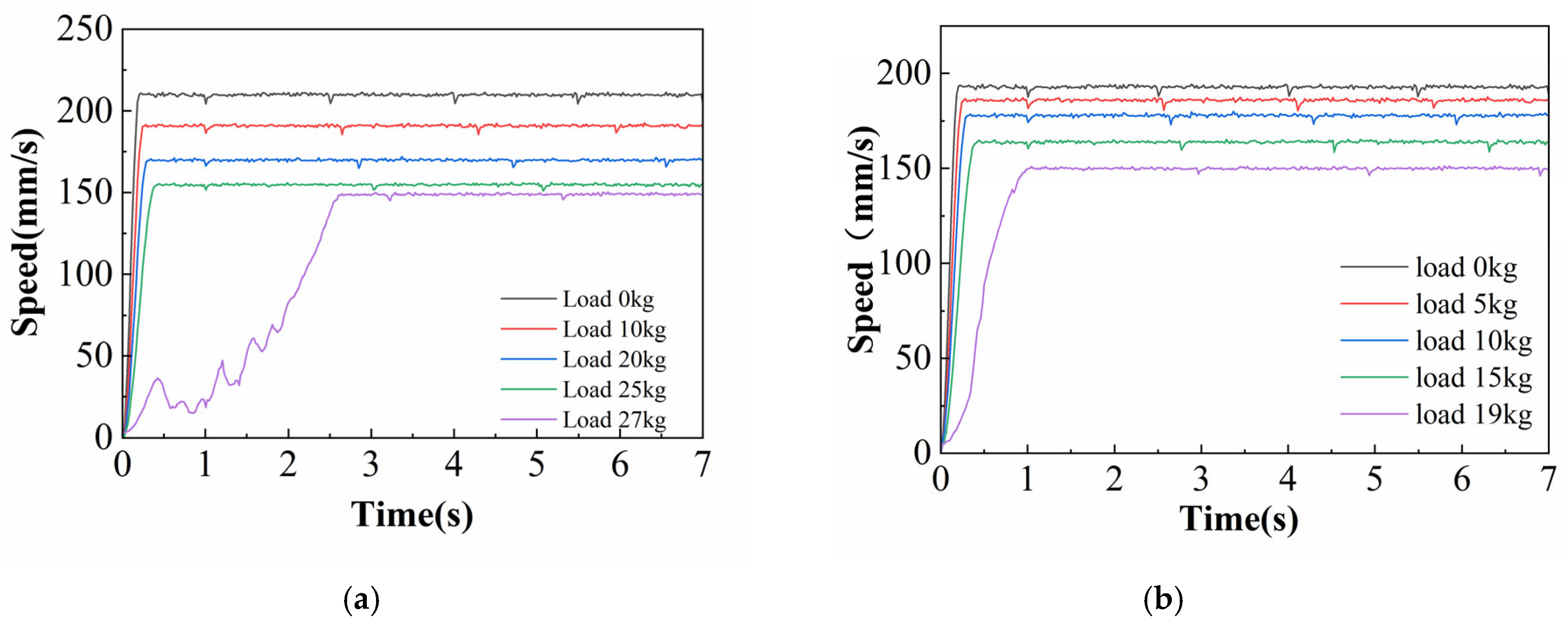
Table 4. During testing, all six driving motors were synchronously controlled at a constant voltage. The maximum sustainable climbing speed and the corresponding limit load were continuously recorded in real time. The climbing process is illustrated in
Figure 8.
Figure 9 presents the test results, showing that increasing the load prolongs the time required to reach steady-state speed and reduces the maximum attainable speed. Additionally, under the same load condition, the climbing mechanism exhibited a significantly higher climbing speed at 45° compared to 90°, indicating that steeper inclination angles impair overall climbing performance.
The tests quantified the climbing mechanism’s maximum load capacity. At 45°, the mechanism successfully supported loads up to 27 kg but failed at 28 kg. The maximum effective load (Load metrics, two load metrics are used at each inclination: (1) maximum load capacity, defined as the highest payload at which the robot does not exhibit sustained backslip or fall (non-slippage threshold), irrespective of speed; and (2) maximum effective load, defined as the highest payload at which the robot maintains the design target speed of 10 m/min without sustained backslip. Unless otherwise stated, “stable operation” in this paper refers to the maximum effective load.) was 20 kg. In contrast, under 90° conditions, the maximum load capacity dropped to 19 kg, with failure at 20 kg, while the effective load limit reduced to 12 kg.
5. Dynamic Simulation
In the preceding section, performance tests were conducted on the physical prototype to determine the friction coefficient and the maximum effective load. This section presents the dynamic simulation and calibration procedures aimed at aligning the simulated results with the performance of the physical prototype under identical test conditions. Comparison with the physical prototype test results is used to further verify the accuracy and reliability of the simulation model.
To accurately simulate the frictional behavior on ice-covered stay cables, ADAMS was selected as the simulation platform in this study. Its built-in stick-slip friction model is capable of maintaining static friction under low-speed or stationary conditions, thereby avoiding the errors commonly introduced by traditional models that cannot preserve stiction [
24]. This feature makes it well-suited for modeling clamping and micro-sliding contact scenarios in the present research. The corresponding workflow is illustrated in
Figure 10.
5.1. Virtual Prototype Established
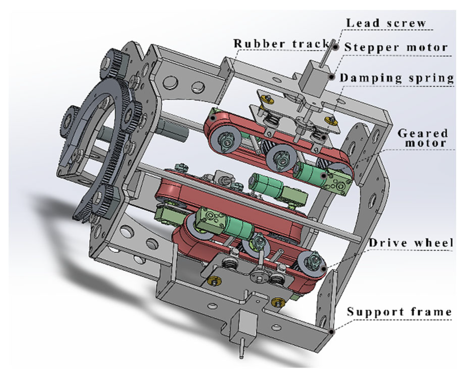
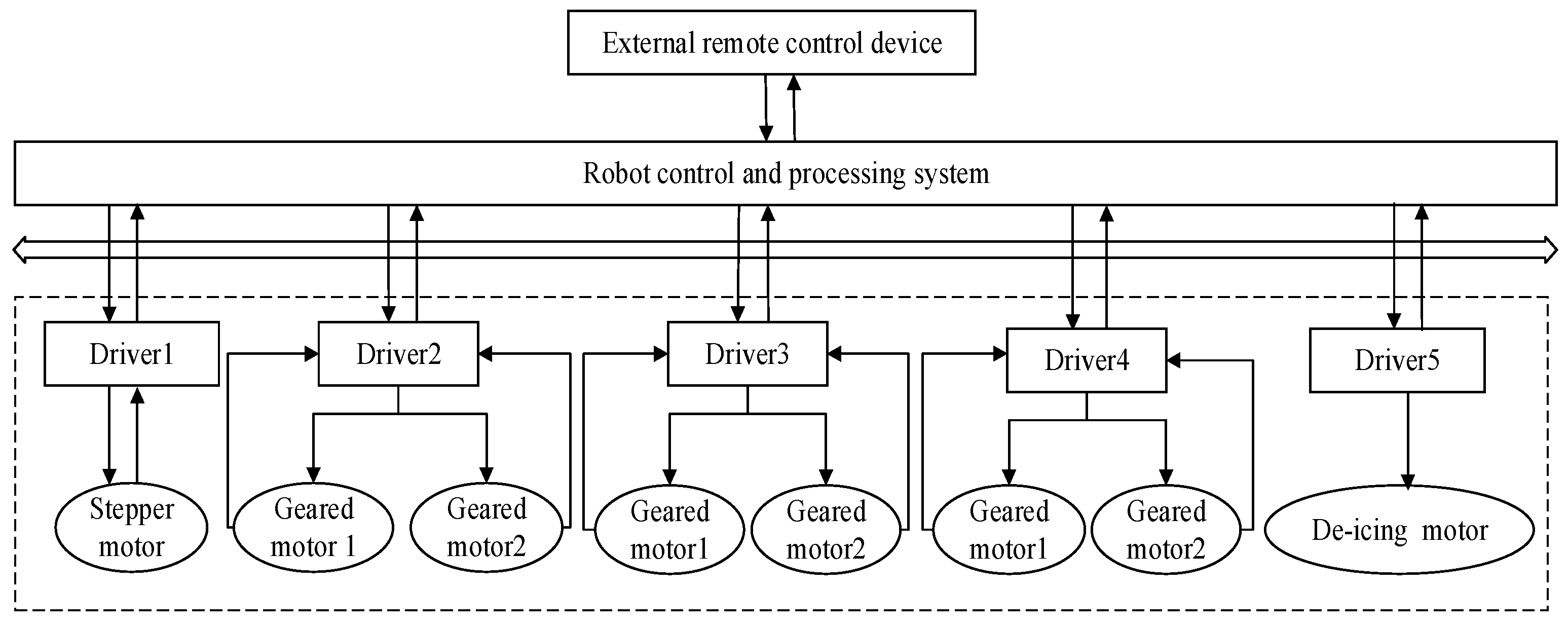
A modular modeling approach was adopted to develop the multi-body dynamic model of the cable-climbing mechanism. A parametric 3D model was constructed using the SolidWorks 2021, followed by a functional decomposition of the mechanism into two main submodules. The driving module consists of six drive wheels, three support wheels, and rubber tracks. The clamping module comprises a lead screw, two support plates, and four damping springs. Interaction between the two modules is realized through the deformation of the spring units, enabling coordinated climbing behavior.
In the ADAMS/View (2020) simulation environment, a complete constraint system was established. A fixed joint was applied between the stay cable and the ground. The lead screw and the locomotion mechanism were modeled using translational joints, and revolute joints were defined between the drive wheels and their corresponding bearings. To ensure motion synchronization, the translational joint of the upper lead screw and the revolute joint of the drive wheel were defined as the active degrees of freedom, the lower units were kinematically constrained to the upper units through coupling relationships, enabling coordinated motion. Finally, contact forces were defined between the drive wheels and the stay cable sheath to simulate the wheel–cable interaction. The virtual model accurately replicates the designed parametric characteristics, as illustrated in
Figure 11.
For computational tractability and to approximate the prototype’s operating state, the feasibility-stage model adopts the following idealizations.
1. The stay cable is represented as rigid and fixed; sag, wind-induced vibration, and deflection under the mechanism’s weight are not modeled.
2. Direct track–cable contact on a flexible cable is outside the present scope. To focus on clamping and traction, contact is represented as drive-wheel–sheath interaction: the sheath is modeled as PVC, the drive wheel as a rigid aluminum-alloy body, with normal contact stiffness set to 1000 (model units). This penalty stiffness keeps peak normal approach (penetration) well below a millimeter fraction of the 35 mm wheel radius while maintaining numerical stability; force/speed time histories are smooth without chatter.
3. Idealized actuation. The drive wheel is speed-prescribed in ADAMS; the solver-reported wheel/output torque is used for feasibility checks. Actuation dynamics (rotor/gearbox inertia, torque ripple, closed-loop control) are not modeled.
During the dynamic simulation using ADAMS, the climbing mechanism was mounted on a 200 mm diameter stay cable sheath. The simulation parameters are listed in
Table 5. A simulation script was developed with 800 iterations and a total simulation time of 8 s. (Here, STEPS = 800 defines an output sampling interval of 0.01 s; the solver’s internal integration step size remains adaptive under local error control and is not fixed at 0.01 s. When spot checks were performed with coarser (0.02 s) and finer (0.005 s) output sampling rates and step caps under the worst-case condition (μ = 0.12, 90° inclination, effective load), the slip/no-slip classification remained unchanged and the time-history responses were visually indistinguishable.) The clamping duration was set to 1 s, followed by a 7 s climbing phase. The gravity vector was reoriented to simulate 45° and 90° gravitational fields by setting directional components, as summarized in
Table 6.
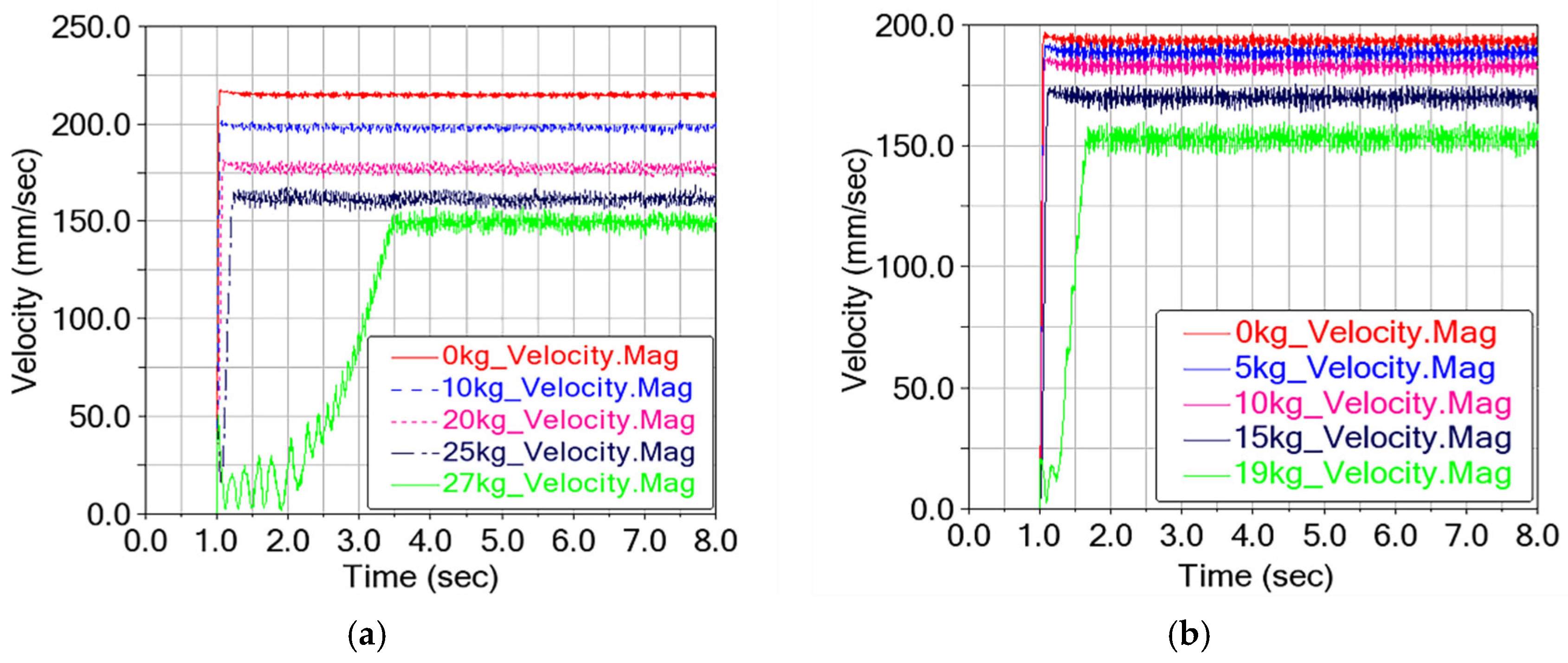
Figure 12 presents the dynamic behavior of the climbing mechanism under 45° and 90° climbing conditions.
5.2. Virtual Prototype Validation
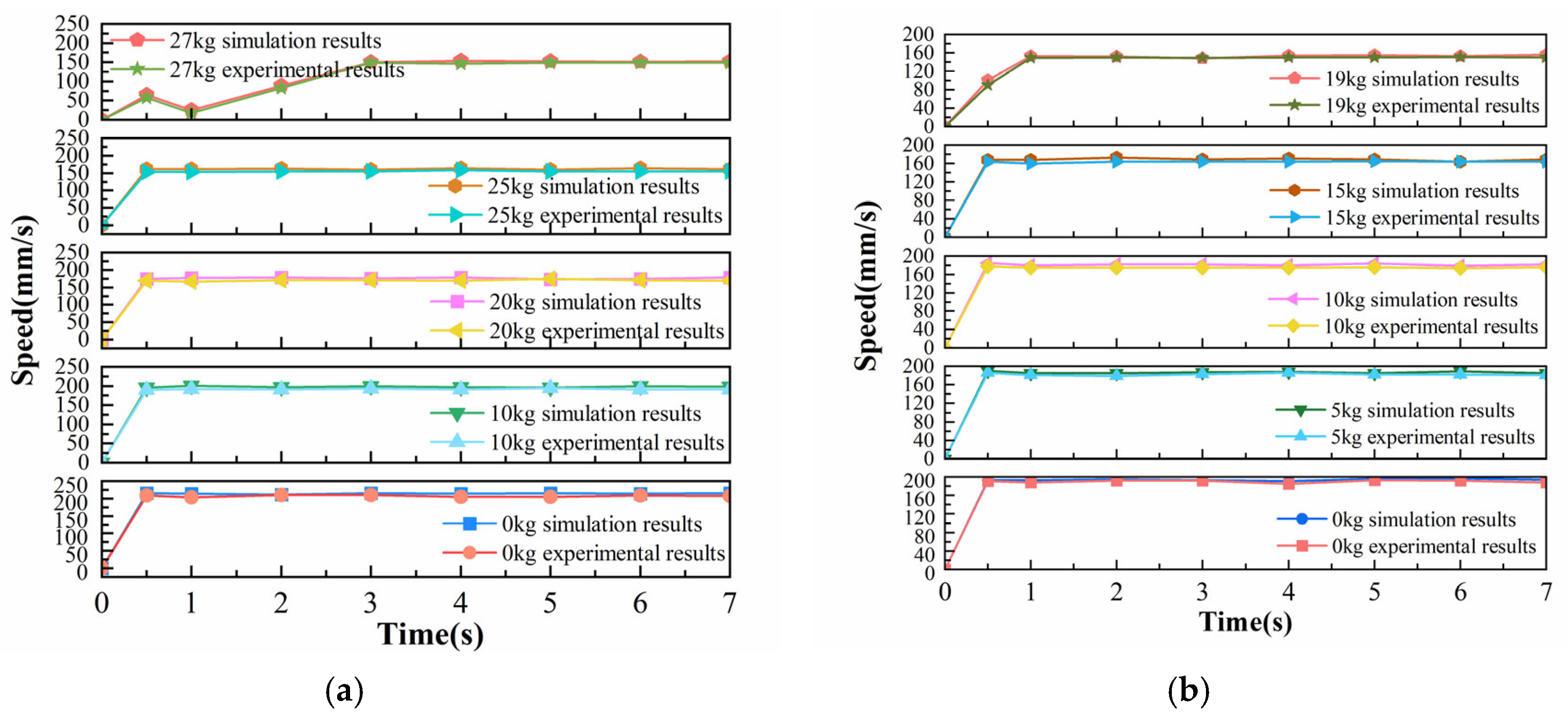
Representative velocity data points covering both the acceleration and steady-state phases were extracted to facilitate validation of the virtual prototype. The climbing speeds of the physical (
Figure 9) and virtual prototypes (
Figure 13) were compared under various loading conditions, and the results are shown in
Figure 14a,b. The test results are generally lower than the simulated results. This discrepancy is attributed to surface-level variations, such as non-uniform ice accumulation, differences in surface hardness, and contaminants on the stay cable sheaths, all of which contribute to local fluctuations in the friction coefficient.
To quantify the agreement between the simulation and test results, the relative root mean square error (RRMSE) was calculated based on the climbing speed data obtained from both the virtual and prototype tests [
25], as shown in
Table 7 and
Table 8. The Relative Root Mean Square Error (RRMSE) was selected for this study because it is a dimensionless metric that enables direct comparison of errors across variables and conditions with different scales. While a slight deviation exists, the RRMSE of climbing speed across varying loads remains below 5%. This level of deviation is considered negligible. Therefore, the virtual model can accurately reflect the physical prototype’s behavior.
6. Parameter Analysis
Previous studies indicate that the inclination angle of stay cables generally ranges from 30° to 90°, while icing-condition tests show that the friction coefficient between the climbing mechanism and the stay cable sheath varies from 0.12 to 0.2. Under these conditions, the mechanism is capable of supporting a maximum effective payload of 12 kg. Based on this data, an extreme working condition is characterized by a 90° inclination angle, a friction coefficient of 0.12, and a 12 kg payload.
Figure 15 illustrates the rationality verification process, which consists of two components:
- (1)
Validation of key component selection: dynamic simulations were conducted in ADAMS/View to evaluate the output torque of the driving wheel and the clamping force provided by the spring under extreme conditions. If the rated output torque of the selected geared motor and the clamping force generated by the damping spring both exceed the corresponding simulated values, the component selection is considered sufficient for the target application.
- (2)
Evaluation of motion stability: the deflection angle and speed of the center of mass were tracked throughout the simulation to assess motion stability. The deflection angle of the center of mass should remain smooth to maintain postural stability, and speed fluctuation should be kept within 10% to ensure continuous and steady climbing.
Additionally, simulations were performed under varying conditions, including inclination angles of 30–90°, friction coefficients from 0.12 to 0.2, and payloads ranging from 0 to 12 kg. The effects of key parameters on the climbing mechanism’s performance were analyzed to support further design optimization and motion control strategy formulation.
Each parameter combination in Table was simulated three times (n = 3) with identical settings. With fixed solver tolerances, ADAMS produced repeatable results; the steady-state value was taken as the mean over 1–8 s, and the fluctuation as (max − min)/mean over the same window. Across repeats, steady-state metrics agreed within ≤1%, and fluctuation estimates within ≤0.5%.
6.1. Component Selection Verification
6.1.1. Critical Clamping Force
Clamping mechanism performance plays a key role in ensuring the safety and efficiency of cable climbing operations. The critical clamping force, a key parameter in climbing performance, is defined as the minimum clamping force required for the cable-climbing mechanism to achieve stable ascent on a stay cable sheath under varying inclinations and surface conditions. A systematic parametric analysis was performed to examine how the friction coefficient, external load, and cable inclination affect the critical clamping force. Detailed parameter settings are provided in
Table 9.
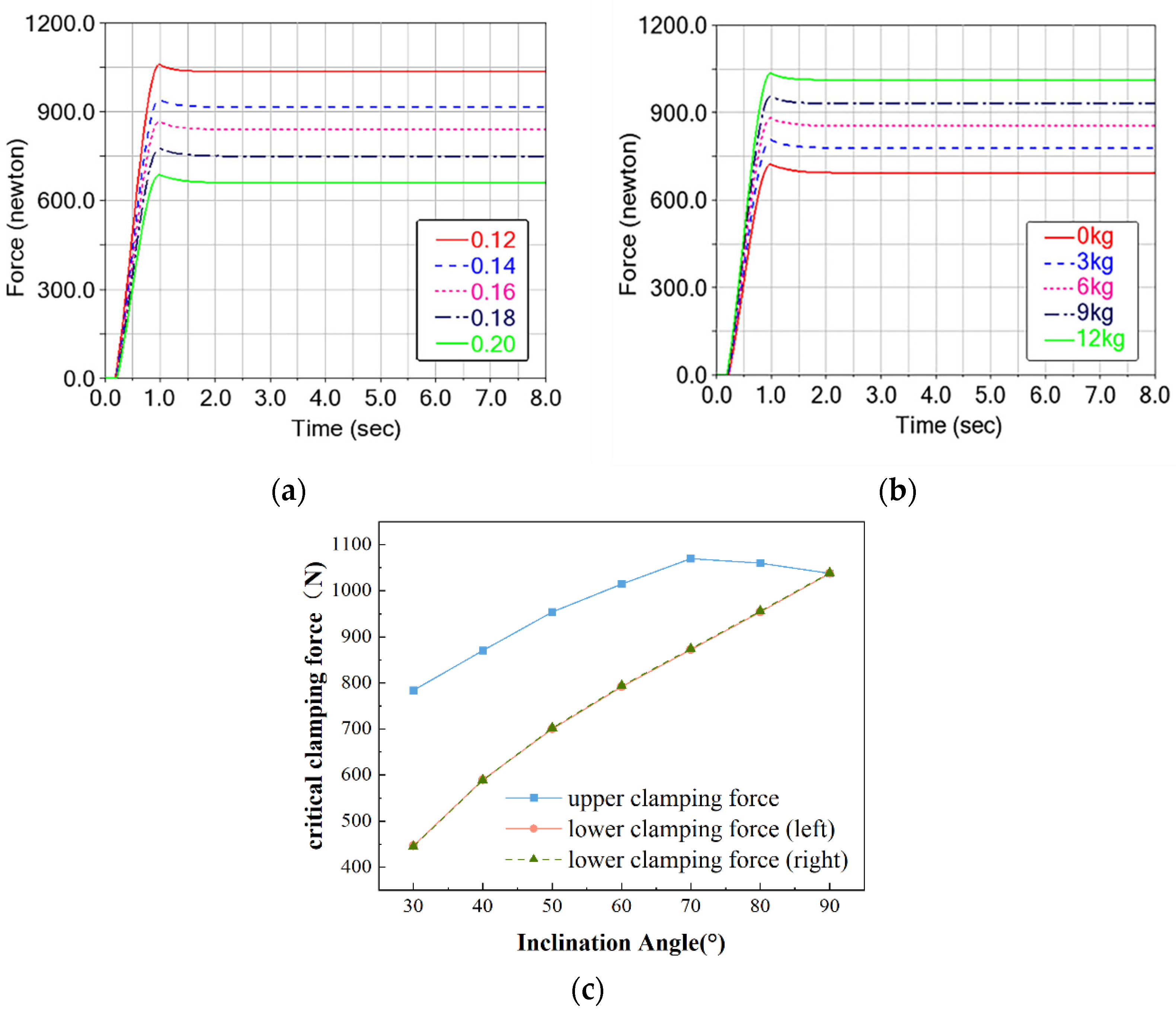
Figure 16 shows the simulation results. Under extreme working conditions, the maximum critical clamping force on a single side is observed near an inclination angle of 70°, reaching 1050 N in the upper module. Meanwhile, the maximum total critical clamping force, resulting from all three clamping modules, is observed at 90° inclination, with each side contributing approximately 1030 N.
Both critical values are below the prototype spring’s maximum clamping capacity (1240 N), indicating adequacy under extreme conditions.
At 90° inclination, the three clamping modules carry equal, symmetrically distributed critical clamping forces. Across friction and load cases, the critical-clamping-force time histories peak within the first second and then settle to a steady state. The critical clamping force decreases with friction (≈5% per +0.01 in μ) (Quantification note: Percentage trends were computed from steady-state means using finite-difference ratios between adjacent conditions) and increases with payload (≈4% per +1 kg). If the external load exceeds the designed effective limit (12 kg), the clamping margin can be restored by adopting higher-stiffness damping springs. The upper module consistently carries more clamping force than the lower modules, and the disparity grows with inclination: the upper-module force rises, peaks near ~70°, then declines, recovering three-way equilibrium at 90°. By contrast, the lower-module force increases with angle. This differential arises because the upper module additionally resists the downslope gravitational component of the mechanism.
6.1.2. Output Torque
The output torque of the climbing mechanism constitutes a pivotal performance parameter that governs both the system’s climbing task execution capability. The output torque is the result of the power source’s original torque after being adjusted by the transmission system, reflecting the system’s capacity to generate rotational motion. We performed dynamic simulations under multiple operating conditions (
Table 10) to quantify how load and inclination angle affect output torque.
As evidenced by the simulation results in
Figure 17, the output torque demonstrates dynamic fluctuations between 4186 and 4874 N·mm. Under the worst-case thin-ice scenario (μ = 0.12, 90° inclination, effective load), the wheel torque settled at ≈4.4 N·m, with occasional peaks approaching but not exceeding 4.905 N·m (motor’s rated output). Thus, the mechanism meets the torque requirement within the idealized-drive assumption.
The output torque exhibits a consistent increasing trend with both applied load and inclination angle across all tested conditions. Specifically, the torque rapidly rises to its peak value within the first second and then maintains a steady state with minor fluctuations. The output torque exhibits consistent evolutionary behavior across all tested operational conditions: the output torque increases with the applied load, showing an approximate 4.7% increase per kilogram increase. It also shows positive correlation with inclination angle, while the output torque continues to grow with steeper angles, this growth becomes less pronounced. As the inclination increases through 30°, 45°, 60°, 75°, and 90°, the incremental torque rise between each successive angle is 30%, 18.7%, 13.9%, and 8.5%, respectively.
6.2. Motion Stability Evaluation
6.2.1. Deflection Angle
Climbing posture is governed by the mechanism’s body deflection angle. Here, the deflection angle is the inclination of the body relative to the direction of travel. Large or rapid deflections degrade motion steadiness and operational efficiency. We therefore use dynamic simulations to quantify how friction coefficient, payload, and stay-cable inclination affect body deflection. These findings inform posture-control strategies under complex environments. Parameter settings and ranges are listed in
Table 11, and results are shown in
Figure 18.
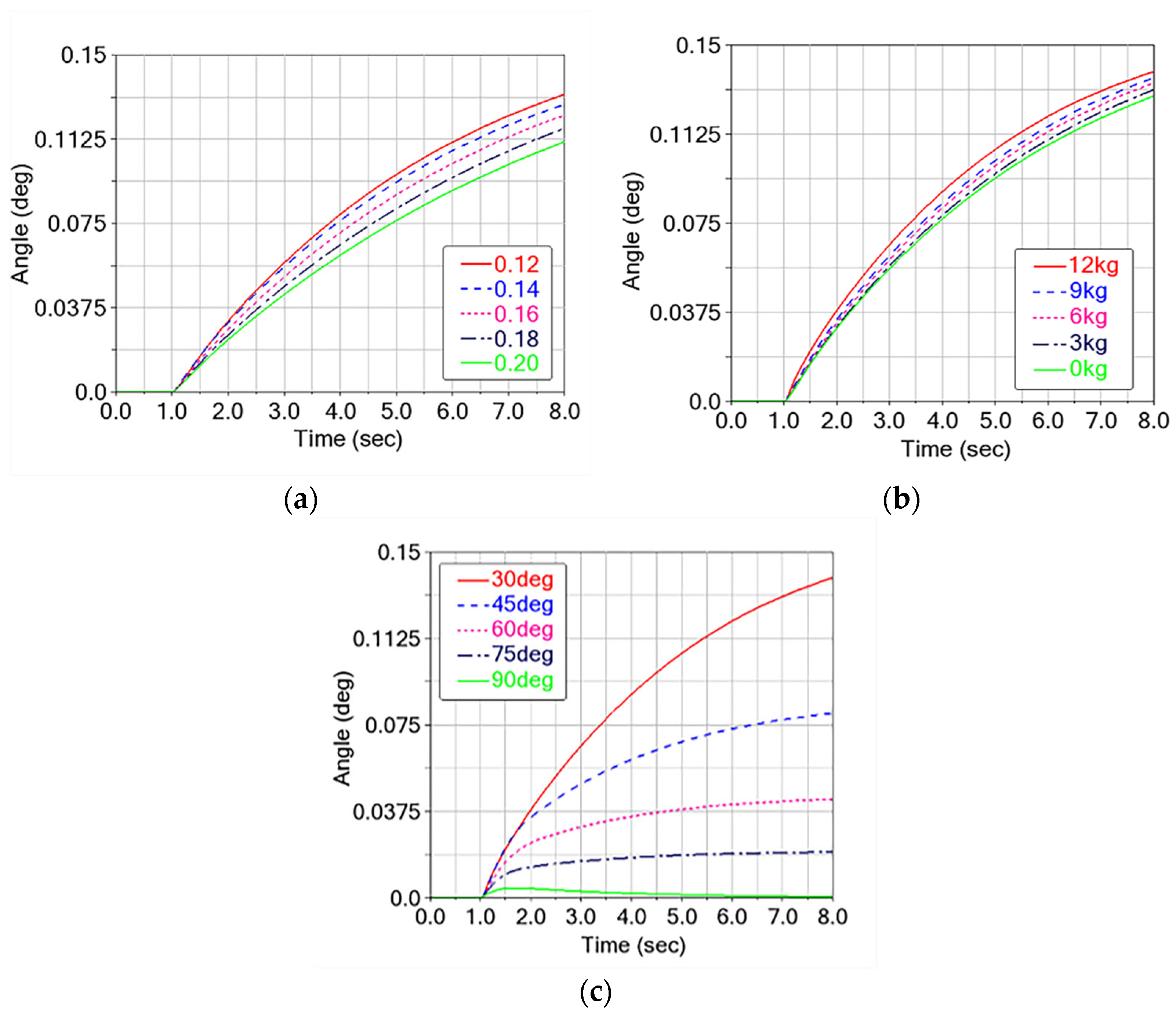
The simulation results demonstrate that the climbing mechanism’s deflection angle increases with decreasing inclination angle. Decreasing inclination angles induces: (1) asymmetric load distribution in the clamping mechanism, and (2) enhanced normal gravitational forces that exacerbate interfacial pressure differences, these effects collectively produce deflection-amplifying torque that peaks at 30°. In contrast, at the 90° vertical position, equilibrium force distribution among the three clamping mechanisms achieves minimal deflection.
The simulation demonstrated under 30° inclination, 12 kg loading, and 0.12 friction coefficient conditions, the climbing mechanism maintained stable posture without abrupt motions. The deflection angle curve showed a steady increase throughout the simulation, meeting the stability requirements of posture.
Deflection angle shows consistent, monotonic growth over the 1–8 s climbing window across friction and load cases. When the friction coefficient increases from 0.12 to 0.20, the growth rate of the deflection angle drops from 0.139° to 0.111° (final steady-state body-deflection angles) (a 25.2% reduction). By contrast, the deflection angle rises from 0.128° to 0.139° as the payload increases from 0 to 12 kg (an 8.6% increase). Thus, lightweighting the de-icing mechanism can improve posture steadiness during climbing.
6.2.2. Motion Speed
Climbing speed is a key performance variable that shapes dynamic steadiness and operational efficiency. Both overly high and overly low speeds can degrade stability, especially under variable friction or time-varying loads. We therefore use dynamic simulations to quantify how key parameters affect speed; parameter settings and ranges are listed in
Table 12.
As shown in
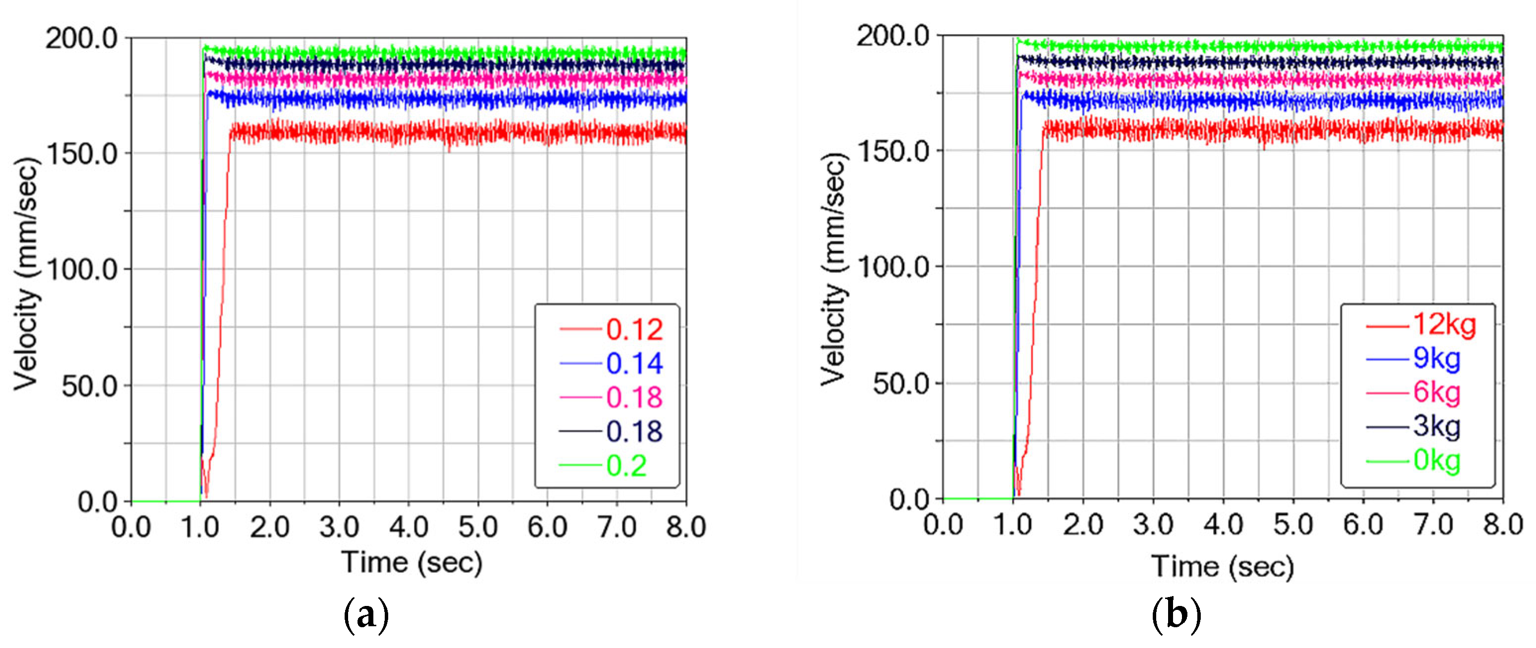
Figure 19, the cable-climbing mechanism maintains a stable speed of 150–163 mm/s (variation < 10%) under extreme conditions. No abrupt fluctuations were observed. As shown in
Figure 19, the cable-climbing mechanism maintains a stable speed of 150–163 mm/s (variation < 10%) under extreme conditions. No abrupt fluctuations were observed, and the stability requirement is met.
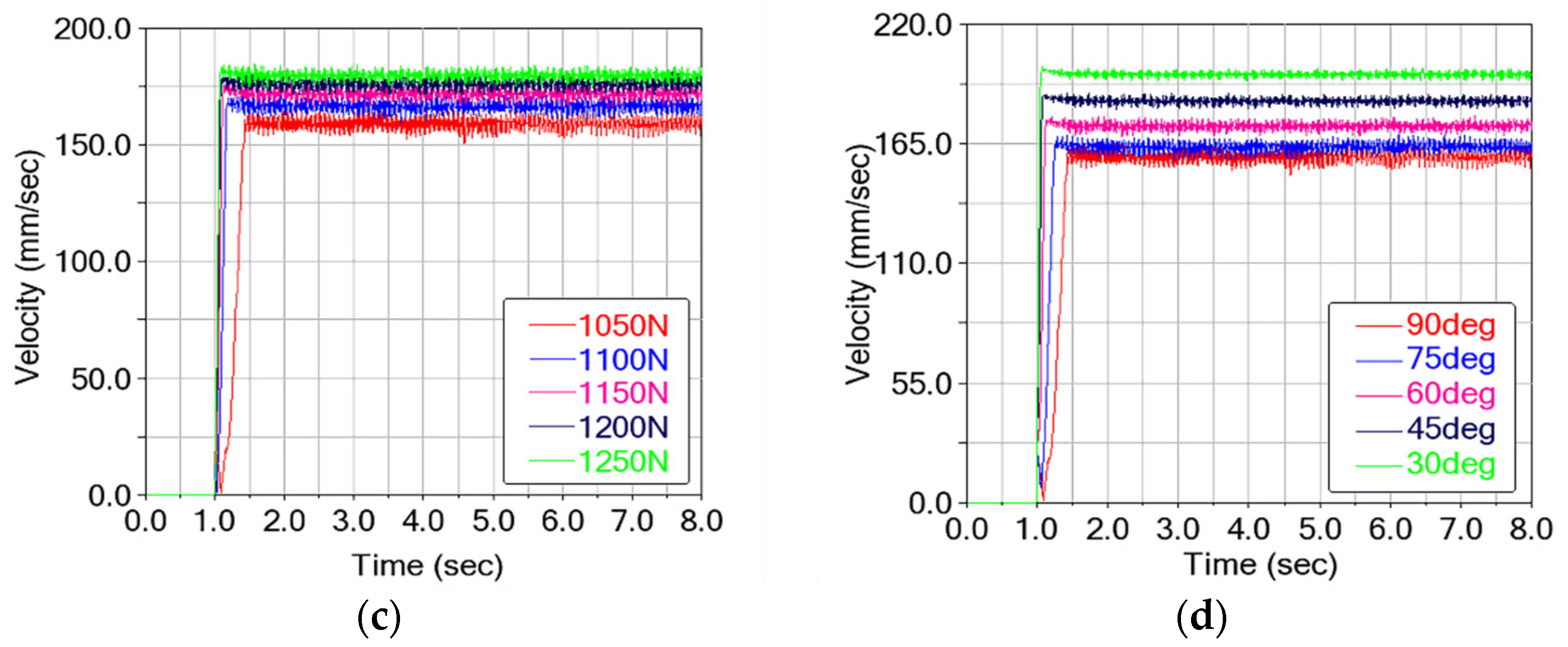
Across variations in friction coefficient, payload, clamping force, and cable inclination, the climbing speed settles within ~1.5 s and then fluctuates slightly about a steady value. Under more extreme conditions (lower μ, higher load, steeper inclination), the settling time increases noticeably.
The friction coefficient and clamping force both increase climbing speed. Increasing μ from 0.12 to 0.20 raises the steady speed from 158 mm/s to 192 mm/s (+21.5%). Increasing clamping force from 1050 N to 1250 N raises speed from 156 mm/s to 179 mm/s (+14.7%). By contrast, speed decreases with payload and inclination. Increasing load from 0 kg to 12 kg reduces steady speed from 194 mm/s to 156 mm/s (−24.3%). Increasing inclination from 30° to 90° lowers speed from 195.9 mm/s to 156 mm/s (−25.6%). Design implications: improve effective friction (via contact materials or contact area), increase clamping force within safety limits, and reduce structural mass to enhance climbing efficiency.
7. Conclusions
This study provides a preliminary validation of the self-clamping cable-climbing mechanism, based on laboratory tests under rigid-support, thin-ice conditions and dynamic simulations incorporating simplified assumptions such as ideal actuation. The following conclusions are drawn:
1. Design rationality and the effective operating range were preliminarily confirmed under controlled laboratory conditions. Experiments on HDPE sheaths with covered thin ice, combined with simulations assuming a rigid cable, demonstrated stable climbing at steep inclinations with high payloads. The mechanism achieved an effective operating load of 12 kg at 90°, with a higher non-slippage limit (e.g., 19 kg at 90°), thereby delineating a feasible parameter range for safe operation under the tested conditions.
2. The high accuracy of the model was validated by an RRMSE of less than 5%, which was calculated from a comparison between the simulated speeds and the speeds measured in laboratory experiments. Despite its rigid-support assumption, the model elucidated key trends and delivered actionable results. These trends offer practical guidance: higher friction reduces clamping needs and stabilizes speed; increased payload raises clamping/torque demand and lowers speed; and the non-linear peak in clamping force near 70° informs critical design and control parameters.
3. The work offers a targeted advance over existing analogues. Unlike robots designed for power lines or dry bridge cables, this mechanism was purpose-validated under thin ice, steep inclinations, and payload. By incorporating explicit safety margins, this study contributes to extending the robot’s validated operational domain toward real-world de-icing conditions, thereby enhancing its potential for practical deployment.
In summary, these results constitute a fundamental preliminary validation under controlled laboratory conditions and with modeled simplifications. Field trials under natural icing, wind, and on flexible stay cables remain essential to fully confirm practical applicability and refine system parameters.
