Article

A Carrier Frequency Offset Estimation Scheme for Underwater Acoustic MIMO-OFDM Communication Based on Sparse Bayesian Learning-Assisted Tentative Channel Estimation

1
School of Information and Electronics, Beijing Institute of Technology, Beijing 100081, China
2
Marine Information Team, Beijing Institute of Technology, Zhuhai 519088, China
3
School of Information and Communication Engineering, Beijing University of Posts and Telecommunications, Beijing 100876, China
*
Author to whom correspondence should be addressed.
Appl. Sci. 2025, 15(19), 10712; https://doi.org/10.3390/app151910712 (registering DOI)
Submission received: 28 August 2025 / Revised: 28 September 2025 / Accepted: 29 September 2025 / Published: 4 October 2025

Abstract

Carrier frequency offset (CFO) estimation is crucial for underwater acoustic (UWA) multiple-input multiple-output orthogonal frequency-division multiplexing (MIMO-OFDM) systems. By employing pilot symbols, a CFO estimation scheme utilizing least squares (LS)-based tentative channel estimation and equalization can achieve an improved CFO estimation performance. However, it suffers from performance degradation due to inaccurate tentative channel estimation in scenarios with relatively long channels or a relatively large number of transmitting transducers. To address this problem, we propose a sparse Bayesian learning (SBL)-based CFO estimation scheme, which employs the expectation-maximization SBL (EM-SBL) algorithm as the tentative channel estimator. In addition, to reduce computational complexity caused by matrix inversion, a refined scheme employing variational Bayesian inference (VBI) technology is proposed, which achieves comparable performance to the original scheme with lower complexity. Finally, numerical simulations demonstrate that our proposed schemes can achieve a remarkably low root mean square error (below 10 2 ) and outperform existing methods across diverse system configurations and simulated channels.

1. Introduction

Due to limited bandwidth, severe multipath effects, and Doppler shifts, the underwater acoustic (UWA) channel is one of the most challenging communication media [1,2,3]. To mitigate multipath interference and enhance data rates in the band-limited UWA channel, multiple-input multiple-output (MIMO) technology combined with orthogonal frequency-division multiplexing (OFDM) modulation has been adopted for UWA communication systems [4,5,6,7,8]. However, the orthogonality among subcarriers may be destroyed by the Doppler shift-induced carrier frequency offset (CFO), leading to inter-carrier interference (ICI) and degraded bit error rate (BER) performance [7,9]. Therefore, it is essential to investigate CFO estimation technologies for UWA MIMO-OFDM systems.
Although numerous CFO estimation techniques for MIMO-OFDM systems have been extensively studied in wireless communications [10,11,12,13], many of them cannot be directly applied to UWA communications due to fundamental differences in channel characteristics. In wireless communication systems, CFO primarily originates from transceiver oscillator mismatches and is generally assumed to be constant within a communication frame. Consequently, most CFO estimation algorithms for wireless MIMO-OFDM systems are derived under this assumption [10,11]. In contrast, in UWA communication systems, CFO is mainly caused by residual Doppler frequency shifts. Owing to the time-varying nature of the ocean environment and relative motions between transceivers, this CFO is usually time-varying within a frame. Therefore, the CFO estimation algorithms developed for wireless communication systems under the constant-CFO assumption cannot be directly applied to UWA communication systems. Furthermore, wireless communication systems offer considerably larger bandwidth than the inherently limited bandwidth in UWA communication systems. As a result, many wireless MIMO-OFDM CFO estimators utilize additional training sequences or known OFDM blocks [12,13]. In contrast, the significantly lower frequency of acoustic waves (compared to electromagnetic waves) results in a naturally constrained and narrower available bandwidth for UWA communication systems.
Given the unique characteristics of UWA channels, some CFO estimation methods have been developed specifically for UWA single-input single-output (SISO) OFDM communication systems [9,14,15]. For instance, a low-complexity CFO estimator based on minimizing null subcarrier energy is proposed in [14]. Nevertheless, this approach inherently sacrifices spectral efficiency due to the use of null subcarriers. In contrast, the cyclic prefix (CP) autocorrelation-based estimator in [15] preserves spectral efficiency. Yet, its accuracy will deteriorate in severe multipath channels. In [9], equally spaced and identical pilot pattern is employed to construct time locality property. A closed-form CFO estimator with low computational complexity and high accuracy is derived based on this property. However, the adopted pilot pattern induces high Peak-to-Average Power Ratio (PAPR).
When it comes to MIMO-OFDM systems, directly applying most of these UWA SISO-OFDM CFO estimation algorithms to UWA MIMO-OFDM systems is challenging, primarily due to co-channel interference (CCI). The algorithm proposed in [14], based on the criterion of minimizing the energy on null subcarriers, is less susceptible to CCI in UWA MIMO-OFDM communication systems. Consequently, this algorithm is readily extended to UWA MIMO-OFDM systems in [7]. This extended algorithm retains advantages such as low computational complexity and high accuracy. It also inherits a significant drawback from the original algorithm, which is a sacrifice in spectral efficiency due to the use of null subcarriers. In [8], a CFO estimation scheme based on pilot subcarriers is proposed. This scheme operates on the principle of minimizing the Euclidean distance between tentatively equalized pilot symbols and their transmitted counterparts. By eliminating the need for null subcarriers, this scheme achieves higher spectral efficiency than the approach in [7]. However, a critical limitation of this scheme is its reliance on the least squares (LS) algorithm for tentative channel estimation. In scenarios with relatively long channels or a relatively large number of transmitting transducers, the LS channel estimation may become ill-posed due to an underdetermined problem. This results in inaccurate tentative channel estimation, consequently leading to severe degradation in CFO estimation performance.
To address this issue, this paper proposes a CFO estimation scheme by leveraging the Expectation-Maximization Sparse Bayesian Learning (EM-SBL) for tentative channel estimation. This scheme maintains high tentative channel estimation accuracy thereby ensuring good CFO estimation performance even under ill-posed conditions, whose probability of occurrence increases with the channel length and the number of transducers. However, this scheme necessitates an exhaustive search over a large candidate CFO set, with each candidate point requiring computationally intensive EM-SBL execution. Consequently, the overall complexity becomes high, scaling dramatically with both the channel length and the number of transducers. To further reduce computational complexity, we introduce a lower-complexity Sparse Bayesian Learning (SBL) channel estimator using Variational Bayesian Inference (VBI), tailored for UWA MIMO-OFDM systems. By employing this VBI-based SBL algorithm as the tentative channel estimator, we finally propose a refined CFO estimation scheme with lower computational complexity.
The rest of the paper is organized as follows. Section 2 introduces the UWA MIMO-OFDM system model and formulates the problem. In Section 3, the proposed CFO estimation scheme based on tentative SBL channel estimation is first developed, and its refined version with lower computational complexity is developed then. A complexity analysis is also provided. Section 4 presents the simulation results to verify the advantages of the proposed schemes. Conclusions are drawn in Section 5.

2. System Model

Consider a co-located UWA MIMO-OFDM communication system [4], comprising N t transmitting transducers and N r receiving hydrophones, shown as Figure 1. In such co-located UWA MIMO-OFDM system, the transmitted data streams from all transmitting transducers can be considered quasi-time-synchronous [16], and the slight timing offset caused by minor timing asynchrony can be absorbed into the channel impulse response (CIR) [12]. Therefore, perfect timing synchronization is assumed. The cyclic prefix (CP) technique is employed to avoid Inter-Symbol Interference (ISI), with the CP length denoted as N cp . Each OFDM block contains N subcarriers. Among these, N P subcarriers are allocated for pilot symbols, with position indices P = I 1 , I 2 , , I N P , and N D subcarriers are allocated for data symbols, with position indices D = J 1 , J 2 , , J N D , satisfying P D = 0 , 1 , , N 1 . All transmitting transducers adopt the same subcarrier mapping scheme, employing an equi-spaced pilot pattern.
In UWA MIMO-OFDM communication systems, a block-by-block processing approach is commonly adopted for handling the received data. The processing method for each OFDM block remains identical [14]. Therefore, without loss of generality, we focus on a single OFDM block. The vector of symbols to be transmitted by the t-th transmitting transducer within an OFDM block can be represented as s t = s t 0 , s t 1 , . . . , s t N 1 T . Let F denote the normalized discrete Fourier transform (DFT) matrix of size N × N , whose element at position i i , j j is 1 N e j 2 π ( i i 1 ) ( j j 1 ) N . The corresponding time-domain signal vector of s t is then given by x t = F H s t = x t 0 , x t 1 , , x t N 1 T . After adding the cyclic prefix (CP), the final time-domain signal vector ready for transmission is expressed as x t = s t N N c p + 1 : N ; s t .
Due to relative motion between the transmitter and receiver, non-uniform Doppler shifts exist in UWA communication systems [14], which should be compensated via a resampling operation [17]. The resampling factor can be estimated using the preamble and postamble signals located in the header and footer of the communication frame. After performing non-uniform Doppler shift compensation, the baseband received signal at time k for the r-th receiving hydrophone can be expressed as [8]
y r k = e j 2 π k ε t , r N t = 1 N t q = 0 N + N c p h t , r k q x t q + w r
where ε t , r denotes the normalized CFO for the transmission data stream from the t-th transmitting transducer to the r-th receiving hydrophone, defined as the ratio of the actual CFO to the subcarrier spacing Δ f . h t , r l l = 0 L c h 1 represents the CIR between the t-th transmitting transducer and the r-th receiving hydrophone, where L c h is the channel length. w r denotes the additive white Gaussian noise (AWGN) with variance σ w 2 .
Rewrite Equation (1) in a compact matrix form. The time-domain received signal vector of the r-th receiving hydrophone y r C N + N c p × 1 can be expressed as
y r = t = 1 N t E t , r H t , r A c p F H s t + w r
where w r denotes the additive white Gaussian noise (AWGN) at the r-th receiving hydrophone. The covariance matrix of w r satisfies E w r w r H = σ w 2 I N . Here, A c p C N + N c p × N is the CP insertion matrix, H t , r C N + N c p × N + N c p is the time-domain channel matrix, and E t , r C N + N c p × N + N c p is the phase rotation matrix induced by the CFO ε t , r :
A c p = 0 N C P × N N c p I N c p I N
E t , r = diag 1 , e j 2 π ε t , r N , . . . , e j 2 π ε t , r N + N C P 1 N
H t , r = h i j N + N c p × N + N c p
where h k = h t , r ( k ) 0 k L ch 1 0 otherwise
In subsequent derivations, it is assumed that the entire MIMO-OFDM system experiences a common CFO [7,8]. Therefore, the subscripts t and r for the CFO matrix are omitted. For the time-domain signal received by the r-th receiving hydrophone, the time-domain signal obtained after tentative CFO compensation y r ̲ C N + N c p × 1 can be expressed as
y r ̲ = E H ε t e n y r
where ε t e n is the tentatively compensated CFO value. Defining the CP removal matrix as R c p = 0 N × N c p I N C N × N + N c p , the time-domain received signal vector y r ̲ ̲ C N × 1 after CP removal can be expressed as
y r ̲ ̲ = R c p y r ̲ = e j 2 π ε ε t e n N c p N Γ ε ε t e n t = 1 N t F H d i a g h t , r f s t + w r
where h t , r f C N × 1 denotes the frequency-domain channel response, and Γ C N × N represents the phase rotation induced by residual CFO after tentative compensation:
h t , r f = F : , 1 : L ch h t , r
Γ ε ε ten = diag 1 , e j 2 π ε ε ten N , , e j 2 π ε ε ten N 1 N
The frequency-domain received signal vector y r f ̲ ̲ C N × 1 can be expressed as
y r f ̲ ̲ = F y r ̲ ̲ = F e j 2 π ε ε t e n N c p N Γ ε ε t e n F H t = 1 N t d i a g h t , r f s t + F w r = M ε t e n t = 1 N t d i a g h t , r f s t + w r f
where M ε t e n reflects the ICI caused by the CFO, and w r f represents the frequency-domain noise:
M ε t e n = F e j 2 π ε ε t e n N c p N Γ ε ε t e n F H
w r f = F w r
If M ( ε ten ) I (i.e., ε t e n ε ), subcarrier orthogonality is destroyed, causing energy leakage between subcarriers. Conversely, if M ( ε ten ) = I (i.e., ε ten = ε ), orthogonality is preserved without energy leakage.
For derivation convenience, assume that the tentative CFO compensation is near-perfect. Thus, the frequency-domain received signal vector y r f ̲ ̲ C N × 1 can be simplified as
y r f ̲ ̲ = t = 1 N t d i a g h t , r f s t + w r f = t = 1 N t d i a g s t F : , 1 : L c h h t , r + w r f
Define the pilot symbol extraction matrix P R N P × N , which extracts N P pilot symbols from the N symbols of the frequency-domain received signal vector y r f ̲ ̲ :
P i , j = 1 i = 1 , , N P , j = I i 0 o t h e r w i s e
Then, the received frequency-domain signal vector at the pilot subcarrier positions, denoted Y r f C N P × 1 , can be expressed as
Y r f = t = 1 N t P d i a g s t F : , 1 : L c h h t , r + w r f , P = U θ r + w r f , P
where θ r = h 1 , r T , , h N t , r T T C N t L c h × 1 , U = [ P d i a g s 1 F : , 1 : L c h , , P d i a g s N t F : , 1 : L c h ] C N P × N t L c h , w r f , P = Pw r f . Based on Equation (7), the channel can be estimated using the least squares method, i.e.,
θ ^ r = U H U 1 U H Y r f
Based on Equation (6), the symbol at the position I p p = 1 , , N p of the frequency-domain received signal vector y r f ̲ ̲ C N × 1 can be expressed as
y r f ̲ ̲ I p = h 1 , r f I p , , h N t , r f I p s 1 I p s N t I p + w r f I p
Stack the y r f ̲ ̲ I p at different receiving hydrophones into a column vector:
Y p = y 1 f ̲ ̲ I p y N r f ̲ ̲ I p = h 1 , 1 f I p h N t , 1 f I p h 1 , N r f I p h N t , N r f I p s 1 I p s N t I p + w 1 f I p w N r f I p = H p S p + w p
To emphasize that this system model is obtained after tentative CFO compensation using ε t e n , we rewrite Equation (10) as Y p ε t e n = H p ε t e n S p + w p ε t e n . Based on Equation (10), the LS equalization result of the pilot symbols can be expressed as
S ^ p ε t e n = H p ε t e n H H p ε t e n 1 H p ε t e n Y p
Using the LS equalization results of the pilot symbols, we can construct a cost function for estimating the CFO:
C ε t e n = t = 1 N t p = 1 N p s ^ t I p s t I p 2
If the CFO is compensated perfectly, i.e., ε t e n = ε , C ε t e n will be relatively small. However, if the CFO is not perfectly compensated, i.e., ε t e n ε , the residual CFO will degrade the accuracy of the channel estimation. This will lead to inaccurate equalization results, resulting in a relatively large C ε t e n . Therefore, the CFO estimation problem can be modeled as the following optimization problem:
ε ^ = arg min ε t e n C ε t e n
The above optimization problem can be solved with relatively low computational complexity via a “coarse one-dimensional search followed by the bisection method” [8]. The accuracy of the channel estimation results directly impacts on the performance of LS equalization. Therefore, accurate channel estimation is crucial for the CFO estimation algorithm based on tentative CFO compensation. However, the LS channel estimation algorithm adopted in CFO estimation scheme proposed in [8] may fail when the number of pilots is limited [5], which are detailed next.
In UWA MIMO-OFDM communication systems with equally-spaced non-orthogonal pilots, the accuracy of the LS channel estimation algorithm relies on two prerequisites: 1. N p N t L c h must hold to prevent the problem from becoming underdetermined; 2. N p L c h must hold to avoid time-domain aliasing in channel estimation when using equally spaced pilot sampling in the frequency domain. In summary, the LS channel estimation algorithm requires N p N t L c h to ensure estimation accuracy. Meeting this condition becomes more and more difficult as the channel length and number of transmitting transducers increase. In contrast, sparse reconstruction-based channel estimation algorithms, which exploit the inherent channel sparsity, depend on only one prerequisite: 1. N p L c h must hold to avoid time-domain aliasing in channel estimation when using equally spaced pilot sampling in the frequency domain. Therefore, sparse reconstruction-based channel estimation algorithms require only 1 / N t the number of pilots required by the LS algorithm.

3. Proposed Method

In this section, we first propose a CFO estimation scheme based on a tentative EM-SBL channel estimation algorithm, which is robust to the situation of long channels or numerous transmitting transducers. This scheme is denoted as the EMSBL-LS-CFOE scheme. Furthermore, to mitigate the heavy computational complexity burden of the EMSBL-LS-CFOE scheme, a refined version of it is proposed utilizing VBI technology. This refined scheme with lower computational complexity is denoted as the VBISBL-LS-CFOE scheme.

3.1. EMSBL-LS-CFOE Scheme

To address the degradation in CFO estimation performance caused by inaccurate tentative LS channel estimation within the scheme proposed in [8] in scenarios with relatively long channels or a relatively large number of transmitting transducers, we employ the EM-SBL algorithm for tentative channel estimation. Unlike the OMP algorithm [18,19], the EM-SBL algorithm does not require prior knowledge of the channel sparsity [20,21]. By incorporating parametric sparse priors within a probabilistic model, it enables automatic estimation of sparse channels along with parameters such as noise variance [22].
Our proposed EMSBL-LS-CFOE scheme operates as follows: First, tentative CFO compensation is applied to the received signals at N r hydrophones. Then, the channel frequency response at pilot subcarriers is estimated using EM-SBL. These estimates are then used to perform LS equalization on pilot symbols. We construct a cost function defined as the sum of squared Euclidean distances between equalized pilot symbols and their transmitted counterparts. Finally, the CFO estimate is obtained via one-dimensional search for the tentative CFO value minimizing this cost function.
For the tentative channel estimation problem Y r f = U θ r + w r f , P described in Equation (7), it can be assumed, without loss of generality, that each element of w r f , P follows an independent and identically distributed complex Gaussian distribution with zero mean and variance σ 2 . Therefore, the likelihood function of Y r f can be expressed as
p Y r f θ r ; β = β π N p exp β Y r f U θ r 2 2
The noise precision β = 1 σ 2 is treated as a random variable and modeled using a Gamma distribution:
p β = γ β ; c , d
Since the vector θ r is sparse, it is modeled as θ r C N ( 0 , d i a g α 1 ) , where α = α 1 , α 2 , α N t L c h T . When most elements in α approach infinity, most elements in θ r approach zero, making the vector θ r sparse. The SBL algorithm enforces this solution sparsity through the following parametric prior:
p θ r α = π N t L c h i = 1 N t L c h α i exp θ r H diag α θ r
The parameter vector α = α 1 , α 2 , , α N t L c h T is also modeled using a Gamma distribution. Each element α i is treated as a random variable and assumed to follow an independent and identically distributed Gamma distribution, leading to
p α = i = 1 N t L c h γ α i ; a , b
where γ · ; · , · denotes the Gamma distribution probability density function. Assuming that α and β are known, the posterior probability density function of θ r can be expressed as
p θ r Y r f ; α , β = p Y r f θ r ; β p θ r ; α p Y r f ; α , β = 1 π N t L c h Σ θ × exp θ r μ θ H Σ θ 1 θ r μ θ
where
μ θ = β Σ θ U H Y r f
Σ θ = d i a g α + β U H U 1
Based on Equation (18), the MAP estimation of θ r can be expressed as
θ r = μ θ
Note that Equation (21) depends on α and β . However, directly estimating α and β is challenging because their posterior probability density lacks an analytical form. Therefore, we employ the EM algorithm to iteratively estimate α and β . Based on Equations (14)–(17), the joint log-likelihood function for all variables is
L = ln p Y r f θ r , β p θ r α p α p β
Ignoring terms in Equation (22) that are independent of α , the optimal α k for the k-th iteration can be obtained by maximizing the following expectation:
E θ r Y r f , α k 1 , β k 1 ln p θ r α k p α k
Taking the derivative of Equation (23) with respect to α k i and setting it to zero yields the update rule for α in the k-th iteration:
α k i = a b + Σ θ ( i , i ) + | μ θ ( i ) | 2 ( i = 1 , 2 , , N t L c h )
Similarly, ignoring terms in Equation (22) that are independent of β , the optimal β k for the k-th iteration can be obtained by maximizing:
E θ r Y r f , α k 1 , β k 1 ln p Y r f θ r , β k p β k
Taking the derivative of Equation (25) with respect to β k and setting it to zero yields the update rule for β in the k-th iteration:
β = c 1 + N p d + Y r f U μ θ 2 2 + tr U Σ θ U H
After the iterations converge, the estimate of the sparse vector θ r can be obtained via Equation (21). The value β final obtained from Equation (26) in the final iteration gives the noise variance estimate σ 2 = 1 β final .
The complete procedure of the proposed EMSBL-LS-CFOE scheme is summarized in Algorithm 1.
Algorithm 1 EMSBL-LS-CFOE Scheme
Input: The size- N t e n CFO candidate array Θ , the threshold e, hyperparameters a, b, c, d;
Initialization: The empty loss function value set Q = , the maximum iteration number of EM algorithm I max , iteration counter k = 0 , α = 1 , 1 , , 1 T , β = 1 ;
Loss function value calculation for all candidate CFOs:
For n t e n = 1 : N t e n do
   Take the n t e n th candidate CFO ε t e n = Θ n t e n ;
   Perform the CFO compensation as in (3);
   Tentative channel estimation via EM-SBL:
   While k I max and μ θ k + 1 μ θ k 2 2 > e do
     Perform E-step per (19) and (20);
     Perform M-step per (24) and (25);
   End while
   Tentative LS equalization on the pilot tones:
   Perform (11);
   Loss function value calculation:
   Perform (12) and add the value to Q ;
End for
Output: Find the minimum of the N t e n loss function values in Q as in (13), and the corresponding CFO candidate is the final CFO estimation result.

3.2. VBISBL-LS-CFOE Scheme

Although our proposed EMSBL-LS-CFOE scheme can solve the performance degradation problem of the CFO estimation scheme proposed in [8] under the situation with long channels or numerous transmitting transducers, it is burdened with heavy computational complexity due to the matrix inversion in E-step of the EM-SBL tentative channel estimation algorithm.
Therefore, we consider decomposing the high-dimensional channel vector into multiple parallel low-dimensional vectors and derive a SBL channel estimation algorithm utilizing variational Bayesian inference (VBI) technology [23]. This VBI-SBL channel estimation algorithm has lower computational complexity than the EM-SBL channel estimation algorithm in MIMO-OFDM systems with long channels or numerous transmitting transducers. Thus, we adopt it as the tentative channel estimation algorithm for our refined CFO estimation scheme, VBISBL-LS-CFOE scheme, whose computational complexity is lower than that of the EMSBL-LS-CFOE scheme proposed in the previous subsection.
In the rest part of this subsection, we first present the VBI-SBL tentative channel estimation algorithm for our system, and then summarize the whole procedure of our proposed VBISBL-LS-CFOE scheme with lower computational complexity in Algorithm 2. Finally, the computational complexity of our proposed EMSBL-LS-CFOE scheme and VBISBL-LS-CFOE scheme is analyzed.
Algorithm 2 VBISBL-LS-CFOE Scheme
Input: The size- N t e n CFO candidate array Θ , the threshold e, hyperparameters c r , d r , a t , r l , b t , r l t = 1 , , N t , l = 0 , , L c h 1 ;
Initialization: The empty loss function value set Q = , the maximum iteration number of VBI algorithm I max , iteration counter k = 0 , α t , r = 1 , 1 , , 1 T t = 1 , , N t , β r = 1 ;
Loss function value calculation for all candidate CFOs:
For n t e n = 1 : N t e n do
   Take the n t e n th candidate CFO ε t e n = Θ n t e n ;
   Perform the CFO compensation as in (3);
   Tentative channel estimation via VBI-SBL:
   While k I max and 1 N t t = 1 N t μ ^ h t , r k + 1 μ ^ h t , r k 2 2 > e do
     Update μ ^ β r : Perform (37);
     Update μ ^ h t , r : Perform (42);
     Update Σ ^ h t , r : Perform (43);
     Update μ ^ α t , r l : Perform (47);
   End while
   Tentative LS equalization on the pilot tones:
   Perform (11);
   Loss function value calculation:
   Perform (12) and add the value to Q ;
End for
Output: Find the minimum of the N t e n loss function values in Q as in (13), and the corresponding CFO candidate is the final CFO estimation result.
For notational convenience, the vector θ r is partitioned into N t vectors of equal length: h t , r = h t , r 0 , h t , r 1 , , h t , r L c h 1 T C L c h × 1 , t = 1 , 2 , , N t . The vector α is denoted as α r to emphasize that it parameterizes the channel estimation for the r-th receiving element. Similarly, α r is partitioned into N t vectors of equal length: α t , r = α t , r 0 , α t , r 1 , , α t , r L c h 1 T C L c h × 1 , t = 1 , 2 , , N t . The parameter β is denoted as β r , indicating that it parameterizes the channel estimation for the r-th receiving hydrophone. Based on the system model in Equation (7), the joint distribution of Y r f , h t , r , β r , α t , r can be factorized as
p h 1 , r , h 2 , r , , h N t , r , α 1 , r , α 2 , r , , α N t , r , β r , Y r f = p Y r f h 1 , r , h 2 , r , , h N t , r , β r × t = 1 N t p h t , r α t , r p α t , r p β r
The prior distributions p β r and p α t , r are
p β r = γ β r ; c r , d r
p α t , r = l = 1 L c h γ α t , r l ; a t , r l , b t , r l
We assume that p h t , r α t , r follows an L c h -dimensional independent complex Gaussian distribution:
p h t , r α t , r = C N ( 0 , diag α t , r 1 ) = l = 0 L c h 1 C N ( h t , r l ; 0 , α t , r l 1 )
Let U = U 1 . U 2 , , U N t . Then, the likelihood function p Y r f h 1 , r , h 2 , r , , h N t , r , β r is
p Y r f h 1 , r , h 2 , r , , h N t , r , β r = β r π N p exp β r Y r f t = 1 N t U t h t , r 2 2
Based on mean-field VBI [23], the posterior probability density function of the hidden variables Θ = h 1 , r , h 2 , r , , h N t , r , α 1 , r , α 2 , r , , α N t , r , β r can be approximated by a variational distribution F r h 1 , r , h 2 , r , , h N t , r , α 1 , r , α 2 , r , , α N t , r , β r . This distribution can be further factorized into 2 N t + 1 independent variational factors f i , i = 1 , , 2 N t + 1 :
F r h 1 , r , h 2 , r , , h N t , r , α 1 , r , α 2 , r , , α N t , r , β r f β r t = 1 N t f h t , r f α t , r
Our goal is to minimize the Kullback–Leibler (KL) divergence between F r · and the true posterior probability density function of the hidden variables:
F ^ r = arg min F r K L F r p ( h 1 , r , h 2 , r , , h N t , r , α 1 , r , α 2 , r , , α N t , r , β r Y r f ) )
The minimization problem in Equation (33) can be transformed into an iterative update process of 2 N t + 1 independent variables [23]. The first step is to update f β r , considering only the terms related to β r in the joint distribution of Equation (27):
ln f * β r p Y r f h 1 , r , h 2 , r , , h N t , r , β r p β r t = 1 N t f h t , r f α t , r
Substituting Equations (28) and (31) into Equation (34) yields
ln f * β r c r 1 + N p ln β r d r + Y r f t = 1 N t U t μ h t , r 2 2 + tr t = 1 N t U t Σ h t , r U t H β r
where μ h t , r and Σ h t , r represent the expectation and covariance matrix of h t , r , respectively. From Equation (35), it can be seen that f β r follows a Gamma distribution:
f β r = γ ( β r ; c r + N p , d r + Y r f t = 1 N t U t μ h t , r 2 2 + tr t = 1 N t U t Σ h t , r U t H )
Thus, the expectation of f β r , μ ^ β r , is
μ ^ β r = c r + N p d r + Y r f t = 1 N t U t μ h t , r 2 2 + tr t = 1 N t U t Σ h t , r U t H
Next, update f h t , r , t = 1 , , N t , considering only the terms related to h t , r in the joint distribution:
ln f * h t , r p Y r f h 1 , r , h 2 , r , , h N t , r , β r × p h t , r α t , r f β r p t N t f h p , r p = 1 N t f α p , r
Substituting Equations (30) and (31) into Equation (38) yields
ln f * h t , r h t , r μ β r μ β r U t H U t + A t , r 1 × U t H Y r f p t N t U p μ h p , r H × μ β r U t H U t + A t , r × h t , r μ β r μ β r U t H U t + A t , r 1 × U t H Y r f p t N t U p μ h p , r
where
A t , r = μ α t , r 0 μ α t , r 1 μ α t , r L c h 1 ,
With μ β r being the expectation of β r , and μ α t , r the expectation of α t , r . Equation (39) shows that f h t , r follows a complex Gaussian distribution:
f h t , r = C N h t , r ; μ ^ h t , r , Σ ^ h t , r
where
μ ^ h t , r = μ β r Σ ^ h t , r U t H Y r f p t N t U p μ h p , r
Σ ^ h t , r = μ β r U t H U t + A t , r 1
Finally, update f α t , r , t = 1 , , N t , considering only the terms related to α t , r in the joint distribution of Equation (27):
ln f * α t , r p h t , r α t , r p α t , r f β r p = 1 N t f h p , r p t N t f α p , r
Substituting Equations (29) and (30) into Equation (44) yields
ln f * α t , r l = 0 L c h 1 [ a t , r l ln α t , r l b t , r l + Σ h t , r l , l + μ h t , r l 2 α t , r l ]
Equation (45) shows that f α t , r l follows a Gamma distribution:
f α t , r l = γ α t , r l ; a t , r l + 1 , b t , r l + Σ h t , r l , l + μ h t , r l 2
Thus, the expectation of f α t , r l is
μ ^ α t , r l = a t , r l + 1 b t , r l + Σ h t , r l , l + μ h t , r l 2
We analyze the computational complexity of our proposed EMSBL-LS-CFOE and VBISBL-LS-CFOE schemes, and compare them with the existing CFO estimation scheme in [8], which is denoted as LS-LS-CFOE. The complexity is measured by the number of complex multiplications (CMs). For simplicity, division operations are treated as multiplication operations, and addition operations are not considered in the computational complexity analysis since their complexity is negligible. The computational complexity comparison is presented in Table 1. Based on the information provided in Table 1, it is evident that the VBISBL-LS-CFOE scheme has lower computational complexity than the EMSBL-LS-CFOE scheme. Moreover, as the channel length L c h and the number of transmitting transducers N t increase, the computational complexity gap between VBISBL-LS-CFOE scheme and EMSBL-LS-CFOE scheme widens.

4. Simulations Results

In this section, the effectiveness of our proposed schemes is demonstrated through numerical simulations. First, the schemes are verified using simulation channels generated by a statistical channel model. They are then further validated using channels generated by Bellhop based on a typical deep-sea sound profile. The numerical simulations were conducted using Python 3.9.
We employ a statistical channel model commonly used in underwater acoustic communications [4,8,19,24]. Channels between each transmitter–receiver pair are mutually independent, with each channel comprising 15 randomly generated multipath components. The inter-path delays follow an exponential distribution with a mean of 2 ms, while path amplitudes follow a Rayleigh distribution. For each signal-to-noise ratio (SNR), 100 Monte Carlo trials are conducted. In each Monte Carlo trial, a new set of MIMO statistical channels is generated. A typical channel realization is shown in Figure 2.
The system simulation parameters are presented in Table 2. We adopt a non-orthogonal pilot pattern, in which different transmit data streams share the same pilot subcarrier positions. Compared with orthogonal pilot patterns, the non-orthogonal pattern provides more available pilot subcarriers for each transmit data stream, which helps improve parameter estimation performance [4,8]. Specifically, the system employs the non-orthogonal pilot pattern proposed in [8]. This pattern is generated by creating N t groups of m-sequences of length 511, truncating each m-sequence to a length of N p , and assigning the resulting N t groups of truncated sequences to the N t transmit data streams as their pilot symbols. In addition, channel coding is not used in our simulation to more clearly show the performance of different CFO estimation schemes.
Based on the aforementioned statistical channel model and system parameters, we simulate two CFO estimation schemes proposed in this paper: EMSBL-LS-CFOE and VBISBL-LS-CFOE. We also simulate the LS-LS-CFOE scheme proposed in [8]. Additionally, the OMP-LS-CFOE scheme is simulated, which is derived from the LS-LS-CFOE scheme in [8] by replacing the tentative LS channel estimation algorithm with the OMP channel estimation algorithm [18]. To finally calculate the BER performance, each scheme’s tentative channel estimation result corresponding to the final CFO estimation result is provided to the LS equalizer to estimate the transmitted data symbols. The simulation results are shown in Figure 3, Figure 4, Figure 5 and Figure 6:
As shown in Figure 3, when the channel length satisfies N p N t < L c h N p , the channel length is long or the number of transducers is large, the performance of the LS channel estimation algorithm degrades significantly as shown in Figure 4, leading to deteriorated CFO estimation performance of the LS-LS-CFOE scheme. The OMP-LS-CFOE scheme introduces the classical sparse reconstruction algorithm OMP for tentative channel estimation. Although OMP exploits prior sparsity to overcome the limitations of LS, the mismatch between the prior sparsity and the actual sparsity results in unsatisfactory tentative channel estimation performance. In contrast, the tentative EM-SBL channel estimation algorithm in our proposed EMSBL-LS-CFOE scheme adapts to the actual sparsity of the channel, achieving desirable tentative channel estimation performance, which consequently leads to improved CFO estimation performance. With lower computational complexity, our proposed VBISBL-LS-CFOE scheme achieves comparable or even slightly better CFO estimation performance than the EMSBL-LS-CFOE scheme. This is because the VBI-SBL channel estimation technique decomposes the high-dimensional channel into N t low-dimensional subchannels, which are then estimated separately. This approach not only reduces computational complexity but also better adapts to the distinct sparsity of each subchannel. As shown in Figure 5, the demodulation bit error rates of communication systems based on our proposed EMSBL-LS-CFOE and VBISBL-LS-CFOE schemes are, across the entire SNR range, close to that of the genie-aided system with perfect CFO estimation and perfect channel state information. Even without specialized optimization of other components in a communication system, our results demonstrate promising BER performance. In this 2 × 2 MIMO system configuration, a satisfactory BER on the order of 10 3 can be achieved at a relatively high SNR, indicating that the CFO has been estimated and compensated effectively. Furthermore, the constellation diagrams of the equalized symbols for different CFO estimation schemes, presented in Figure 6, provide intuitive visual confirmation of the conclusions drawn from the BER performance analysis in Figure 5. In addition, it should be noted that all the four simulated CFO estimation schemes have equal data rate:
R b = 2 × 768 × 2 0.2123 = 14.470 kb / s
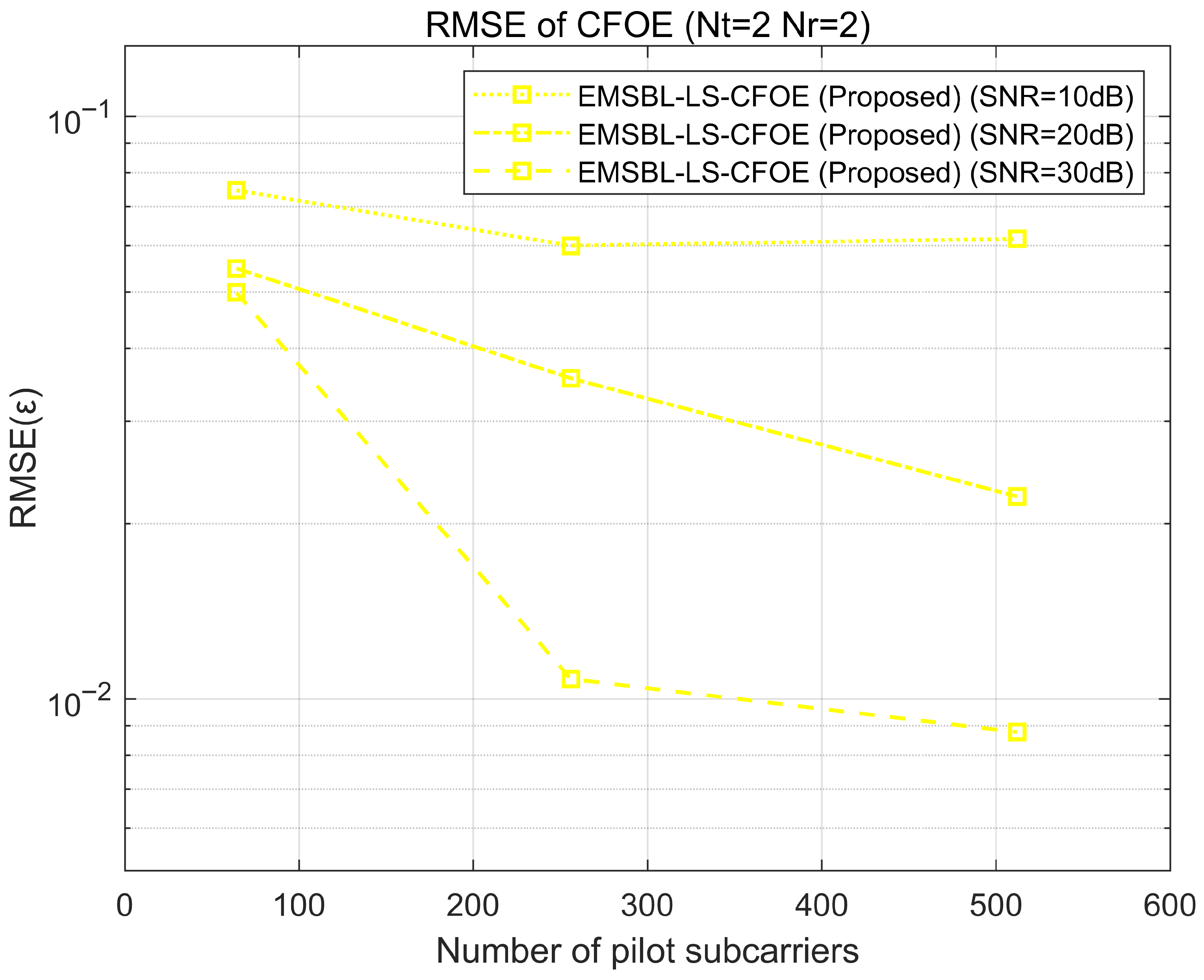
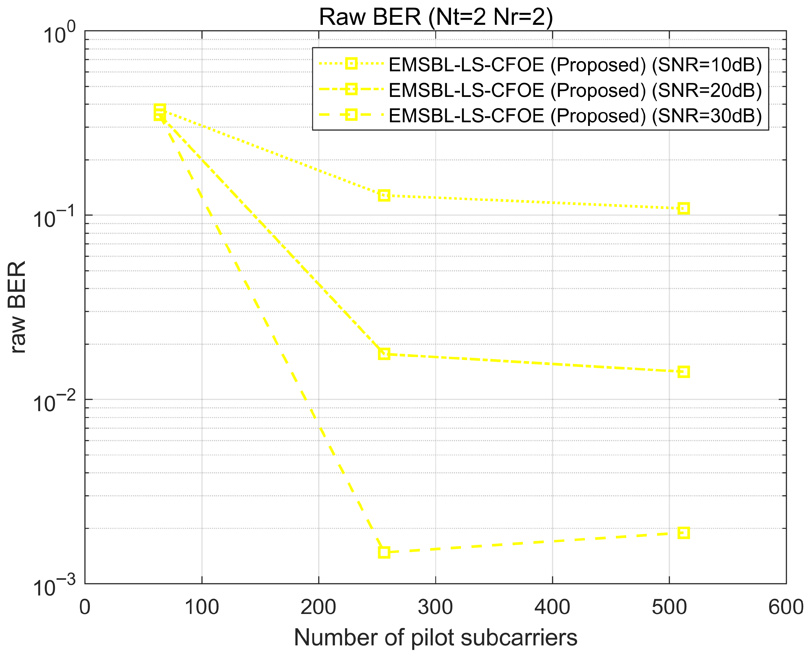
Additional simulations are conducted to demonstrate the performance of our proposed schemes under different numbers of pilot subcarriers and different modulation order. As shown in Figure 7, Figure 8 and Figure 9, the CFO estimation performance of our proposed scheme improves as the number of pilot subcarriers increases. However, when the number of pilot subcarriers is too low, the CFO estimation performance degrades due to a lack of measurement data required for the SBL algorithms. As shown in Figure 10, Figure 11 and Figure 12, the proposed CFO estimation schemes maintain robustness against higher-order modulations. This inherent advantage stems from the fact that our CFO estimation relies solely on the tentatively equalized pilot symbols, which in turn depends on the tentative channel estimation. The high-accuracy tentative channel estimation techniques employed in our proposed schemes use only the pilot symbols on pilot subcarriers and is therefore independent of the modulation order of data subcarriers. Consequently, the CFO estimation performance remains robust regardless of the modulation order. However, as observed in the BER curves of Figure 12, the 16-QAM situation exhibits slightly higher BER compared to the QPSK situation at the same SNR. This is expected and attributable to the reduced Euclidean distance between constellation points in higher-order modulations, which increases the difficulty of equalization and symbol detection, rather than being a limitation of our CFO estimation schemes.
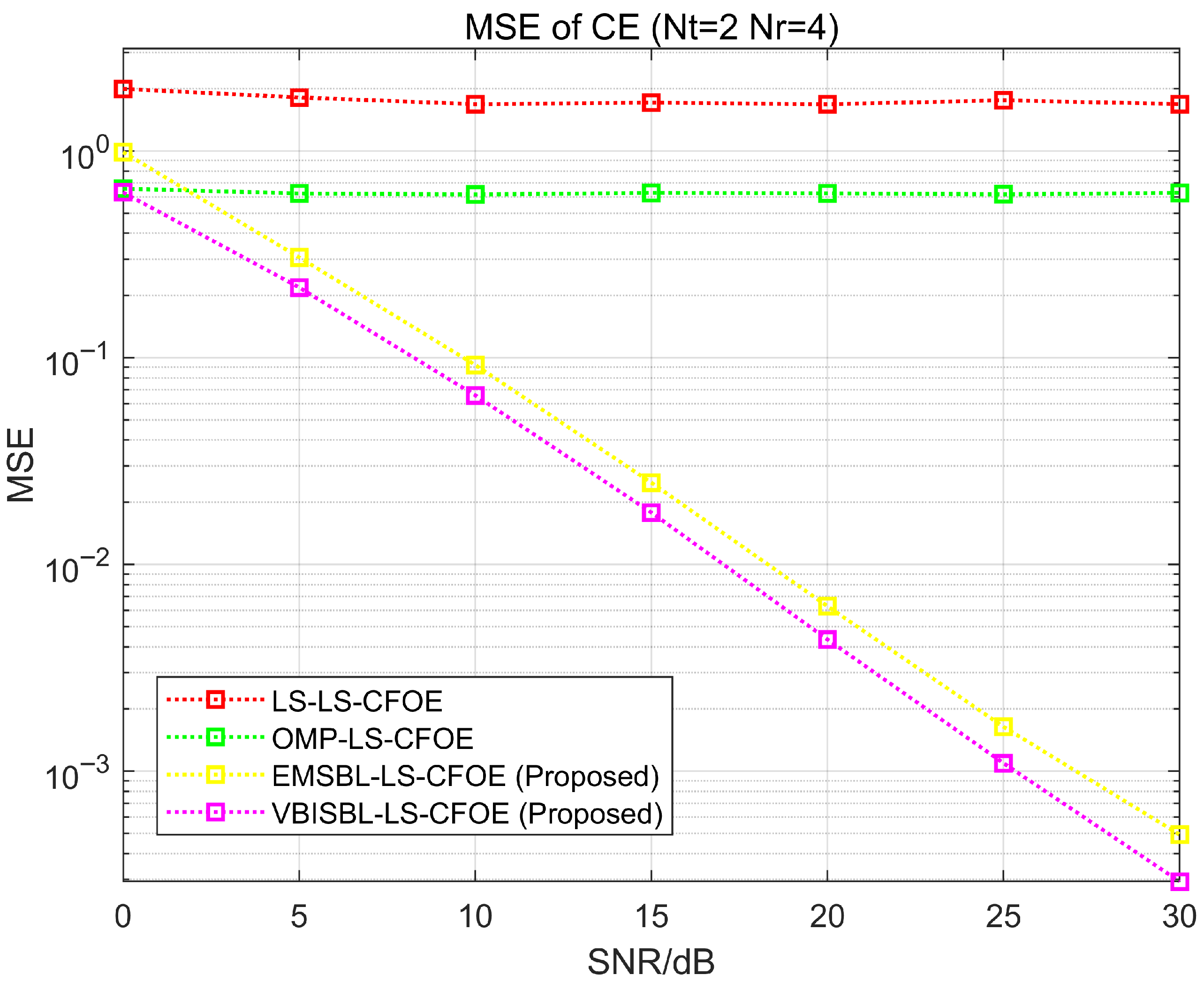
To demonstrate the performance of our proposed schemes under asymmetric MIMO configurations, we further consider a MIMO system where the number of transmitting transducers differs from the number of receiving hydrophones, i.e., N t = 2 , N r = 4 . The corresponding simulation results are shown in Figure 13, Figure 14 and Figure 15. As observed from Figure 13, the CFO estimation performance for the 2 × 4 MIMO configuration is superior to that of the 2 × 2 MIMO configuration at the same SNR. This improvement is attributed to the spatial diversity gain, which enhances the performance of the tentative equalization, thereby leading to more accurate CFO estimation. Furthermore, the improved CFO estimation accuracy subsequently results in better channel estimation performance for the 2 × 4 MIMO configuration compared to the 2 × 2 MIMO configuration case, as shown in Figure 14. Finally, Figure 15 demonstrates that the BER performance of the 2 × 4 MIMO configuration is significantly better than that of the 2 × 2 MIMO configuration under the same SNR. This overall gain stems from the combined benefits of improved CFO estimation, enhanced channel estimation, and the direct boost to equalization performance provided by the spatial diversity gain.
To demonstrate the performance of our proposed schemes in different MIMO system configurations, we further consider a MIMO system with more transmitting transducers and receiving hydrophones, i.e., N t = N r = 4 . The corresponding simulation results are shown in Figure 16, Figure 17 and Figure 18. As can be observed from Figure 16, Figure 17 and Figure 18, as the number of transmitting transducers increase, our proposed schemes can maintain satisfactory CFO estimation performance.
To validate our proposed schemes in different types of UWA channels, we further simulated a deep-sea channel using Bellhop [25,26]. The deep-sea sound speed profile (SSP) and the simulated UWA channels generated based on this SSP are shown in Figure 19 and Figure 20, respectively. The simulation results of our proposed schemes under these Bellhop-simulated channels are shown in Figure 21, Figure 22 and Figure 23. It can be seen that our proposed schemes can maintain satisfactory CFO estimation performance, demonstrating their robustness to different types of UWA channels.
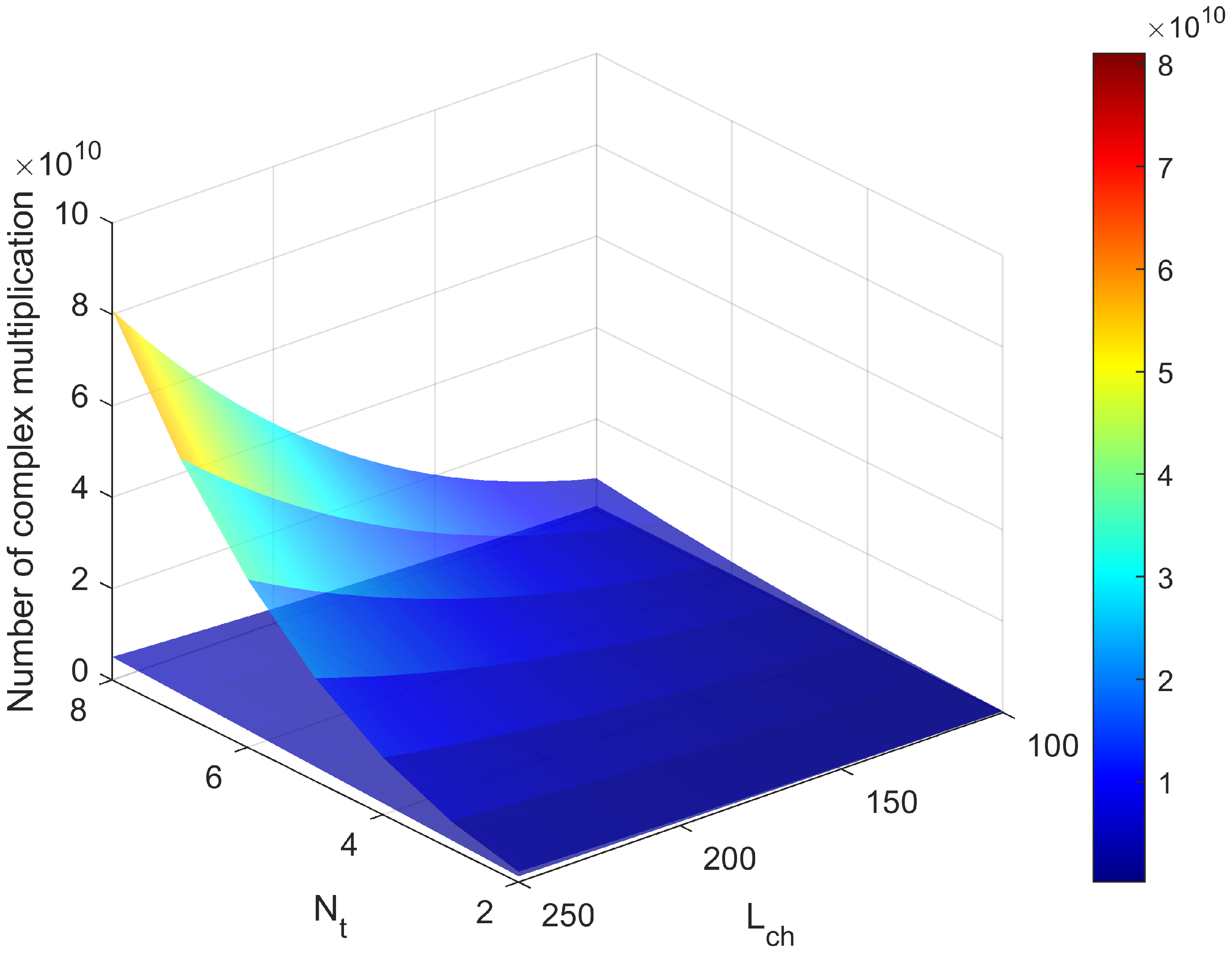
Finally, to directly compare the computational complexity, the number of complex multiplication operations required by the proposed EMSBL-LS-CFOE and VBISBL-LS-CFOE schemes is calculated under varying numbers of transmitting transducers and channel lengths. As shown in Figure 24, the proposed VBISBL-LS-CFOE scheme consistently requires fewer operations than the EMSBL-LS-CFOE scheme. Moreover, this computational complexity advantage widens as the number of transmitting transducers and the channel length increase.

5. Conclusions

In this paper, we proposed a CFO estimation scheme for UWA MIMO-OFDM communications. The scheme employs the EM-SBL algorithm to ensure accurate tentative channel estimation, leading to accurate CFO estimation in scenarios with relatively long channels or a relatively large number of transmitting transducers. In addition, a refined version of this scheme was proposed, utilizing VBI to reduce computational complexity. Compared with the existing CFO estimation scheme based on LS tentative channel estimation, our proposed schemes provide better CFO estimation accuracy in the aforementioned challenging scenarios, as validated by numerous numerical simulations. The superior performance of our proposed schemes is also reflected in the channel estimation accuracy and overall system BER. The robustness of our proposed schemes has been validated under diverse MIMO system configurations and simulated channels. In all these test cases, our schemes maintain stable and superior performance compared to existing methods.
For future work, the feasibility of the proposed CFO estimation schemes will be further analyzed in realistic UWA channels. Sea trials are planned to validate the methods in real-world environments. Additionally, the performance of the schemes will be investigated in clustered-sparse UWA channel scenarios.

Author Contributions

Conceptualization, Z.L., H.Z. and L.X.; methodology, Z.L. and H.Z.; software, Z.L. and Q.Z.; investigation, Z.L. and H.Z.; writing—original draft preparation, Z.L.; writing—review and editing, Z.L. and H.Z.; supervision, L.X. All authors have read and agreed to the published version of the manuscript.

Funding

This work was financially supported by the National Natural Science Foundation of China (Grant No. 62192712).

Data Availability Statement

The data presented in this study are available on request from the corresponding author. The data are not publicly available due to intellectual property.

Conflicts of Interest

The authors declare no conflicts of interest.

Abbreviations

The following abbreviations are used in this manuscript:
CFOCarrier Frequency Offset
UWAUnderwater Acoustic
MIMOMultiple-Input Multiple-Output
OFDMOrthogonal Frequency-Division Multiplexing
LSLeast Squares
EMExpectation Maximization
SBLSparse Bayesian Learning
VBIVariational Bayesian Inference
ICIInter-Carrier Interference
BERBit Error Rate
SISOSingle-Input Single-Output
CPCyclic Prefix
CCICo-Channel Interference
PAPRPeak-to-Average Power Ratio
CIRChannel Impulse Response
ISIInter-Symbol Interference
DFTDiscrete Fourier Transform
AWGNAdditive White Gaussian Noise
SSPSound Speed Profile

References

  1. Stojanovic, M.; Preisig, J. Underwater acoustic communication channels: Propagation models and statistical characterization. IEEE Commun. Mag. 2009, 47, 84–89. [Google Scholar] [CrossRef]
  2. Li, J.; Chen, F.; Liu, S.; Yu, H.; Ji, F. Estimation of Overspread Underwater Acoustic Channel Based on Low-Rank Matrix Recovery. Sensors 2019, 19, 4976. [Google Scholar] [CrossRef] [PubMed]
  3. Xu, X.; Wang, Z.; Zhou, S.; Wan, L. Parameterizing both path amplitude and delay variations of underwater acoustic channels for block decoding of orthogonal frequency division multiplexing. J. Acoust. Soc. Am. 2012, 131, 4672–4679. [Google Scholar] [CrossRef]
  4. Li, T.; Zhou, F.; Ma, L.; Jia, H.; Liu, X.; Muzzammil, M. Non-orthogonal pilot pattern design and sparse channel estimation for underwater acoustic MIMO-OFDM systems. Appl. Acoust. 2024, 220, 109933. [Google Scholar] [CrossRef]
  5. Chen, W.; Tao, J.; Ma, L.; Qiao, G. Vector-Approximate-Message-Passing-Based Channel Estimation for MIMO-OFDM Underwater Acoustic Communications. IEEE J. Ocean. Eng. 2024, 49, 496–506. [Google Scholar] [CrossRef]
  6. Li, T.; Zhou, F.; Ma, L.; Liu, X.; Muzzammil, M. Multipath DOA based MIMO beamforming receiver scheme for high-rate underwater acoustic communications. Appl. Acoust. 2024, 221, 109994. [Google Scholar] [CrossRef]
  7. Li, B.; Huang, J.; Zhou, S.; Ball, K.; Stojanovic, M.; Freitag, L.; Willett, P. MIMO-OFDM for High-Rate Underwater Acoustic Communications. IEEE J. Ocean. Eng. 2009, 34, 634–644. [Google Scholar] [CrossRef]
  8. Tao, J. DFT-Precoded MIMO OFDM Underwater Acoustic Communications. IEEE J. Ocean. Eng. 2018, 43, 805–819. [Google Scholar] [CrossRef]
  9. Amar, A.; Avrashi, G.; Stojanovic, M. Low Complexity Residual Doppler Shift Estimation for Underwater Acoustic Multicarrier Communication. IEEE Trans. Signal Process. 2017, 65, 2063–2076. [Google Scholar] [CrossRef]
  10. Zhang, W.; Yin, Q.; Gao, F. Computationally Efficient Blind Estimation of Carrier Frequency Offset for MIMO-OFDM Systems. IEEE Trans. Wirel. Commun. 2016, 15, 7644–7656. [Google Scholar] [CrossRef]
  11. Ito, K.; Takahashi, T.; Ishibashi, K.; Igarashi, K.; Ibi, S. Joint Channel, CFO, and Data Estimation via Bayesian Inference for Multi-User MIMO-OFDM Systems. IEEE Trans. Wirel. Commun. 2025, 24, 1898–1915. [Google Scholar] [CrossRef]
  12. Chen, J.; Wu, Y.C.; Ma, S.; Ng, T.S. Joint CFO and Channel Estimation for Multiuser MIMO-OFDM Systems with Optimal Training Sequences. IEEE Trans. Signal Process. 2008, 56, 4008–4019. [Google Scholar] [CrossRef]
  13. Moose, P. A technique for orthogonal frequency division multiplexing frequency offset correction. IEEE Trans. Commun. 1994, 42, 2908–2914. [Google Scholar] [CrossRef]
  14. Li, B.; Zhou, S.; Stojanovic, M.; Freitag, L.; Willett, P. Multicarrier Communication Over Underwater Acoustic Channels with Nonuniform Doppler Shifts. IEEE J. Ocean. Eng. 2008, 33, 198–209. [Google Scholar] [CrossRef]
  15. Wan, L.; Jia, H.; Zhou, F.; Muzzammil, M.; Li, T.; Huang, Y. Fine Doppler scale estimations for an underwater acoustic CP-OFDM system. Signal Process. 2020, 170, 107439. [Google Scholar] [CrossRef]
  16. Huang, J.; Zhou, S.; Wang, Z. Performance Results of Two Iterative Receivers for Distributed MIMO OFDM with Large Doppler Deviations. IEEE J. Ocean. Eng. 2013, 38, 347–357. [Google Scholar] [CrossRef]
  17. Sharif, B.; Neasham, J.; Hinton, O.; Adams, A. A computationally efficient Doppler compensation system for underwater acoustic communications. IEEE J. Ocean. Eng. 2000, 25, 52–61. [Google Scholar] [CrossRef]
  18. Tropp, J.A.; Gilbert, A.C. Signal Recovery From Random Measurements via Orthogonal Matching Pursuit. IEEE Trans. Inf. Theory 2007, 53, 4655–4666. [Google Scholar] [CrossRef]
  19. Berger, C.R.; Zhou, S.; Preisig, J.C.; Willett, P. Sparse Channel Estimation for Multicarrier Underwater Acoustic Communication: From Subspace Methods to Compressed Sensing. IEEE Trans. Signal Process. 2010, 58, 1708–1721. [Google Scholar] [CrossRef]
  20. Tipping, M.E. Sparse bayesian learning and the relevance vector machine. J. Mach. Learn. Res. 2001, 1, 211–244. [Google Scholar] [CrossRef]
  21. Qiao, G.; Song, Q.; Ma, L.; Liu, S.; Sun, Z.; Gan, S. Sparse Bayesian Learning for Channel Estimation in Time-Varying Underwater Acoustic OFDM Communication. IEEE Access 2018, 6, 56675–56684. [Google Scholar] [CrossRef]
  22. Wang, S.; He, Z.; Niu, K.; Chen, P.; Rong, Y. New Results on Joint Channel and Impulsive Noise Estimation and Tracking in Underwater Acoustic OFDM Systems. IEEE Trans. Wirel. Commun. 2020, 19, 2601–2612. [Google Scholar] [CrossRef]
  23. Tzikas, D.G.; Likas, A.C.; Galatsanos, N.P. The variational approximation for Bayesian inference. IEEE Signal Process. Mag. 2008, 25, 131–146. [Google Scholar] [CrossRef]
  24. Ballal, T.; Al-Naffouri, T.Y.; Ahmed, S.F. Low-Complexity Bayesian Estimation of Cluster-Sparse Channels. IEEE Trans. Commun. 2015, 63, 4159–4173. [Google Scholar] [CrossRef]
  25. Tong, W.; Ge, W.; Han, X.; Yin, J. A low-complexity algorithm based on variational Bayesian inference for MIMO channel estimation. Appl. Acoust. 2023, 211, 109512. [Google Scholar] [CrossRef]
  26. Yin, J.; Zhu, G.; Han, X.; Guo, L.; Li, L.; Ge, W. Temporal Correlation and Message-Passing-Based Sparse Bayesian Learning Channel Estimation for Underwater Acoustic Communications. IEEE J. Ocean. Eng. 2024, 49, 522–541. [Google Scholar] [CrossRef]
Figure 1. Co-located UWA MIMO-OFDM system.
Applsci 15 10712 g001
Figure 2. Typical channel simulation results utilizing statistical channel model. (a) Channel between the first transducer and the first hydrophone. (b) Channel between the first transducer and the second hydrophone. (c) Channel between the second transducer and the first hydrophone. (d) Channel between the second transducer and the second hydrophone.
Applsci 15 10712 g002
Figure 3. RMSE performance of various CFOE schemes (2 × 2 MIMO, QPSK).
Applsci 15 10712 g003
Figure 4. MSE performance of CE of various CFOE schemes (2 × 2 MIMO, QPSK).
Applsci 15 10712 g004
Figure 5. BER performance of communication systems with various CFOE schemes (2 × 2 MIMO, QPSK).
Applsci 15 10712 g005
Figure 6. Constellation diagram of equalized symbols (2 × 2 MIMO, QPSK). (a) Constellation diagram for LS-LS-CFOE scheme. (b) Constellation diagram for OMP-LS-CFOE scheme. (c) Constellation diagram for EMSBL-LS-CFOE scheme. (d) Constellation diagram for VBISBL-LS-CFOE scheme. (e) Constellation diagram for Genie-aided situation.
Applsci 15 10712 g006
Figure 7. RMSE performance of proposed CFOE scheme (under different numbers of pilot subcarriers).
Applsci 15 10712 g007
Figure 8. MSE performance of CE of proposed CFOE scheme (under different numbers of pilot subcarriers).
Applsci 15 10712 g008
Figure 9. BER performance of communication systems with proposed CFOE scheme (under different numbers of pilot subcarriers).
Applsci 15 10712 g009
Figure 10. RMSE performance of various CFOE schemes (16QAM).
Applsci 15 10712 g010
Figure 11. MSE performance of CE of various CFOE schemes (16QAM).
Applsci 15 10712 g011
Figure 12. BER performance of communication systems with various CFOE schemes (16QAM).
Applsci 15 10712 g012
Figure 13. RMSE performance of various CFOE schemes (2 × 4 MIMO).
Applsci 15 10712 g013
Figure 14. MSE performance of CE of various CFOE schemes (2 × 4 MIMO).
Applsci 15 10712 g014
Figure 15. BER performance of communication systems with various CFOE schemes (2 × 4 MIMO).
Applsci 15 10712 g015
Figure 16. RMSE performance of various CFOE schemes (4 × 4 MIMO).
Applsci 15 10712 g016
Figure 17. MSE performance of CE of various CFOE schemes (4 × 4 MIMO).
Applsci 15 10712 g017
Figure 18. BER performance of communication systems with various CFOE schemes (4 × 4 MIMO).
Applsci 15 10712 g018
Figure 19. Deep sea sound speed profile.
Applsci 15 10712 g019
Figure 20. Bellhop simulated channel results. (a) Channel between the first transducer and the first hydrophone. (b) Channel between the first transducer and the second hydrophone. (c) Channel between the second transducer and the first hydrophone. (d) Channel between the second transducer and the second hydrophone.
Applsci 15 10712 g020
Figure 21. RMSE performance of various CFOE schemes.
Applsci 15 10712 g021
Figure 22. MSE performance of CE of various CFOE schemes.
Applsci 15 10712 g022
Figure 23. BER performance of communication systems with various CFOE schemes.
Applsci 15 10712 g023
Figure 24. Comparison of computational complexity between EMSBL-LS-CFOE and VBISBL- LS-CFOE.
Applsci 15 10712 g024
Table 1. Comparison of number of complex multiplication operations.
CFOE SchemeComplex Multiplication
Operations of Tentative
Channel Estimation Algorithm
Complex Multiplication
Operations of Tentative
Equalization Algorithm
LS-LS-CFOE N r N t 3 L c h 3 + N r N t 2 L c h 2 ( N p + 1 ) + N r N t L c h N p N p ( N t 3 + N t 2 N r + N t 2 + N t N r )
EMSBL-LS-CFOE N r + N r N p + 2 N r N t L c h + 2 N r N t L c h N p + N r N t L c h N p 2 + 2 N r N t 2 L c h 2 N p + N r O ( N t 3 L c h 3 ) N p ( N t 3 + N t 2 N r + N t 2 + N t N r )
VBISBL-LS-CFOE N r + N r N p + 2 N r N t L c h + N r N t L c h N p + N r N t 2 L c h N p + N r N t L c h N p 2 + 3 N r N t L c h 2 N p + N r N t O ( L c h 3 ) N p ( N t 3 + N t 2 N r + N t 2 + N t N r )
Table 2. System simulation parameters.
ParameterValue
Number of transmitting transducers N t 2
Number of receiving hydrophones N r 2
Bandwidth B6 kHz
Number of subcarriers N1024
Number of pilot subcarriers N p 256
Number of data subcarriers N d 768
Length of CP N C P 250
Modulation type M o d type QPSK
Disclaimer/Publisher’s Note: The statements, opinions and data contained in all publications are solely those of the individual author(s) and contributor(s) and not of MDPI and/or the editor(s). MDPI and/or the editor(s) disclaim responsibility for any injury to people or property resulting from any ideas, methods, instructions or products referred to in the content.