Abstract
This paper presents a hardware-in-the-loop (HIL) simulation case study on the application of High-Order Sliding Mode Control (HOSMC) to a flexible-link robotic arm. The developed HIL platform combines physical hardware components with a simulated plant model, enabling real-time testing of control algorithms under realistic operating conditions without requiring a full-scale prototype. HOSMC, an advanced nonlinear control strategy, mitigates the chattering effects inherent in conventional sliding mode control by driving the system to a reduced-order sliding manifold within a finite time, resulting in smoother actuator commands and reduced mechanical stress. Flexible-link arms, while lightweight and energy-efficient, are inherently nonlinear and prone to vibration, posing significant control challenges. In this case study, the experimental HIL environment is used to evaluate HOSMC performance, demonstrating improved trajectory tracking, reduced overshoot, and minimized steady-state error. The results confirm that HIL simulation offers an effective bridge between theoretical control design and practical implementation for advanced robotic systems.
1. Introduction
The Hardware-in-the-Loop (HIL) simulator developed in this study serves as an experimental testbed for direct-drive (DD) robotic systems, with a particular focus on flexible-link arms. The platform integrates physical hardware—including DD motors, hub angular position sensors, and industrial motion controllers—with a MATLAB (R2022b)/Simulink-based real-time simulation environment.
Since direct-drive (DD) actuators eliminate gear mechanisms, actuator dynamics play a critical role in achieving high-performance control. This configuration provides several advantages, including the elimination of backlash, improved precision, and reduced friction. However, it also has disadvantages such as high current demand and limited torque capacity, and these characteristics are directly reflected in control performance [1]. The proposed HIL setup incorporates an actual hub unit with a DD motor, angular position feedback, a real motion controller, and a second DD motor mechanically coupled to emulate the load dynamics of a flexible-link arm.
The primary objective of this study is to test and validate nonlinear control strategies for position and trajectory tracking in real time, thereby enabling rapid prototyping and performance evaluation prior to full-scale implementation. HIL simulation provides an efficient, low-risk, and cost-effective development process by revealing mechanical and control issues without requiring a complete physical prototype. This approach has been widely adopted in aerospace [2], automotive [3], motion control [4], and mechatronics [5], and is increasingly applied in robotics [6], where real hardware is integrated into simulated environments.
Key benefits of HIL simulation include:
- Simulating large, complex, and costly electromechanical systems using minimal hardware.
- Safely testing equipment under extreme or hazardous conditions (e.g., space, deep sea, or planetary environments).
- Mitigating risks in systems involving hazardous or high-energy components.
Over the past decade, HIL systems have been applied across a wide range of domains, including multi-joint planar robots with dynamic load emulation [7], aircraft control systems incorporating real hydraulic components [8], high-current power system stabilization [9], and wave energy converters (WEC) with power take-off (PTO) systems [10]. In robotics, recent applications include fluidic artificial muscle actuation [11], ground testing of space manipulators [12], spacecraft attitude control [13], integration with solar photovoltaic systems [14], and virtual HIL environments that combine Unreal Engine with MATLAB/Simulink for industrial gantry robots [5]. Furthermore, HIL setups have been adopted in control education to enhance laboratory-based reinforcement learning experiments [15,16].
Flexible-link robotic systems remain a challenging and attractive research topic in control engineering due to their nonlinear dynamics and vibration characteristics. Such manipulators are widely used in applications where link flexibility strongly affects end-effector positioning or joint dynamics, including space robotics, high-precision industrial assembly, and lightweight robotic arm design [17,18]. Accurate modeling and effective control of these systems are therefore of critical importance. Most existing experimental studies focus on dedicated arms with fixed parameters [19,20]. By contrast, the proposed HIL setup supports a variety of flexible arms with different shapes and physical parameters, enabling broader testing scenarios. In this context, robust control strategies such as adaptive control, sliding mode control, and fuzzy logic control have gained prominence. More recently, integrated approaches such as adaptive sliding mode control (ASM), barrier function-based methods [21], fuzzy logic systems, state observers, and command-filtering techniques [22] have been explored.
Given these challenges, Sliding Mode Control (SMC) is particularly suitable for flexible-link robotic systems because it inherently addresses parameter uncertainties, nonlinear behaviors, and external disturbances. SMC has long been a preferred method in robotic systems and electric drives due to its strong robustness against such effects [23,24]. However, its main drawback—chattering—can cause performance degradation and hardware stress in practical applications. To mitigate this limitation, advanced variants such as High-Order Sliding Mode Control (HOSMC) and the Super-Twisting Algorithm (STA) have been developed, producing smoother control signals and improving accuracy and stability [13,25,26,27]. More recent adaptive extensions, including Adaptive Super-Twisting Global SMC (ASTGSMC) for flexible manipulators, have further enhanced robustness [28]. In addition, H∞-based SMC has demonstrated superior rejection of unmatched disturbances, particularly in robotic manipulators and vehicle systems [29]. These advancements confirm SMC’s position as one of the most effective and reliable control strategies across diverse applications, ranging from flexible manipulators [30] to multi-input multi-output motor drives.
The main contribution of this paper is the development of a flexible, real-time testbed for evaluating and implementing high-performance nonlinear control strategies in direct-drive (DD) flexible-link robotic systems. The platform facilitates controller tuning, accommodates diverse control approaches, and provides a user-friendly interface for real-time experimentation. The setup consists of two identical DD motors rigidly coupled via a shaft: one motor emulates the flexible-link dynamics as a load, while the other operates as the actuator under control.
The remainder of the paper is organized as follows: Section 2 presents the dynamic modeling and control of the DD flexible-link robotic arm. Section 3 describes the hardware and software architecture of the HIL simulator. Section 4 discusses implementation details and experimental results, and Section 5 provides concluding remarks.
2. Dynamics and Control of the Flexible-Link Robotic Arm
This study considers a Hardware-in-the-Loop (HIL) simulation of a flexible-link robotic arm, which is classified as an underactuated system due to the presence of multiple vibration (mode) shapes in its dynamics. The inclusion of these shape modes results in a highly coupled, nonlinear mathematical structure, making both modeling and control challenging.
To achieve accurate set-point and trajectory tracking, advanced nonlinear control strategies are required. In this work, Sliding Mode Control (SMC) is employed, and to mitigate the chattering effect inherent to conventional SMC, a High-Order Sliding Mode Control (HOSMC) scheme is implemented within the HIL framework. The HIL setup enables practical design, tuning, and testing of such nonlinear controllers under realistic, real-time conditions.
2.1. Dynamic Equations of Motion
The equations of motion for the 1-DOF direct-drive (DD) flexible-link robotic arm are derived under the following assumptions:
- The beam undergoes small elastic deformations, represented by generalized coordinates.
- Second-order elastic deformation terms of the form qi, qj are negligible.
The schematic representation of the flexible-link arm is illustrated in Figure 1.
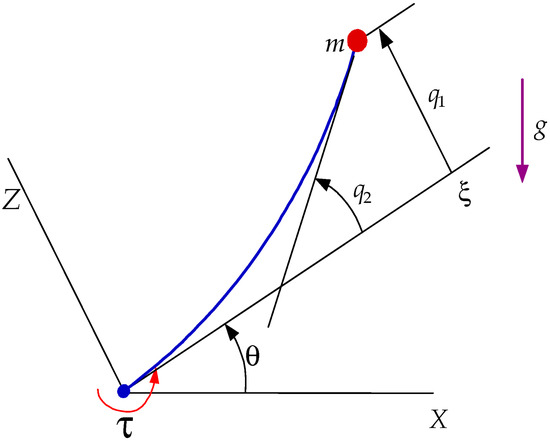
Figure 1.
Schematic of flexible link arm.
Using Lagrange’s method combined with a finite element approximation of the beam deformation, the system dynamics can be expressed as [17]:
where M(q) is the mass matrix, represents Coriolis and centrifugal terms, Kq accounts for elastic stiffness forces, and N(q) contains the nonlinear terms associated with the flexible dynamics.
In these equations, τ is the applied torque to the manipulator and is the friction torque consisting of viscous ( and Coulomb friction ( terms.
2.2. Derivation of the Control Signal
Nonlinear systems rarely allow a single universal control solution. Thus, experimental evaluation through HIL simulation is advantageous, as it enables accurate analysis and controller tuning before deploying to a full-scale prototype.
In this work, both SMC and an r-th order HOSMC with continuous control input are designed for the flexible-link arm described by (1). For a general motion control system with relative degree r, the dynamics can be expressed as:
Sliding Manifold Selection
The first sliding manifold is chosen as:
where θd is the desired tip position. The objective of control is to ensure:
σ1 = θd − y
This manifold defines the objective of minimum deviation of the tip-position from the desired position, θd. A control law is sought based on the Lyapunov theory to ensure that,
To this aim, the following choices are made for the positive definite Lyapunov function and its derivative in the derivation of the r-HOSMC:
To satisfy the Lyapunov conditions, select
The objective is to find a control law that will fulfill
as a result of which , hence .
The following relationship will also be satisfied.
For i = r then with , also known as the equivalent control, such that
Combining (7) and (8), the following equation is obtained:
Next, by discretizing (8),
and (9),
The assumption that equivalent control is in fact the average control leads to approximation,
which helps to combine (9) and (10) and hence, yields the control signal in the following form.
3. HIL Setup
The Hardware-in-the-Loop (HIL) setup developed in this study integrates physical components from the target system with a real-time simulation environment, enabling accurate evaluation of control strategies under realistic operating conditions. Leveraging modern high-speed microelectronics and computing technologies, the setup operates in real time with a sampling frequency of 10 kHz that allows dynamic testing of the flexible-link robotic arm model with varying system parameters, trajectories, and control schemes. A block diagram of the overall HIL system is shown in Figure 2. The detailed parameters of the components utilized in the HIL setup are summarized in Table 1.
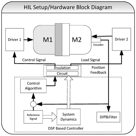
Figure 2.
Hardware-in-the-Loop (HIL) system block diagram showing integration of hardware and real-time simulation environment. The setup includes two direct-drive (DD) motors with encoders, motor drivers, and a DSP controller card. The primary motor serves as the actuator under control, while the secondary motor emulates flexible-link dynamics. Position feedback and control signals are exchanged in real time via DAC/ADC channels.

Table 1.
Parameters of the components used in the HIL Setup.
3.1. HIL Setup Hardware Structure
The HIL platform is built around two high-torque, high-speed direct-drive (DD) motors, their corresponding drivers, and a dedicated Digital Signal Processing (DSP) controller card. DD actuators are used to reproduce realistic actuator dynamics, which are critical for high-performance control design in flexible-link robotic arms.
The primary motor serves as the controlled actuator, while the secondary motor is mechanically coupled via a shaft to emulate the dynamic effects of the flexible link on the hub. Both motors are equipped with incremental encoders for precise angular position feedback.
The motor drivers operate from a single-phase AC input and generate a three-phase output, with each motor capable of producing up to 15 Nm of torque. The DSP card handles the following tasks in real time:
- Generating setpoints and reference trajectories.
- Computing the control torque for the actuator motor.
- Producing load torques via the secondary motor to simulate flexible-link dynamics.
Through its Digital-to-Analog Converter (DAC) channels, the DSP card outputs the control signals to the motor drivers. Position feedback from the encoders is processed by the DSP for closed-loop control.
3.2. HIL Setup Software Structure
The controller hardware was selected to ensure high computational performance and full compatibility with MATLAB/Simulink, allowing seamless integration between model-based design and real-time execution. Controlling algorithms, system dynamics, and trajectory generation routines are implemented in Simulink, then automatically converted into C code using Real-Time Workshop (RTW) and compiled for execution on the DSP card.
The software architecture comprises three main functional modules:
- Trajectory Planning and Generation—Defines desired position and velocity profiles for the actuator.
- Torque Computation for the Load Simulator—Calculates the torque demand for the secondary motor to emulate flexible-link dynamics.
- Control Signal Generation for the Actuator—Produces the final control input based on feedback and the selected nonlinear control algorithm.
The HIL system operates with a sampling frequency of 10 kHz and an average computational latency of approximately 100 µs, ensuring reliable real-time performance of the implemented control algorithms.
Real-time monitoring and data logging are supported via TRACE32(R6.5), which provides live visualization of system variables and records results in *. mat format for offline analysis. A schematic of software architecture is shown in Figure 3.
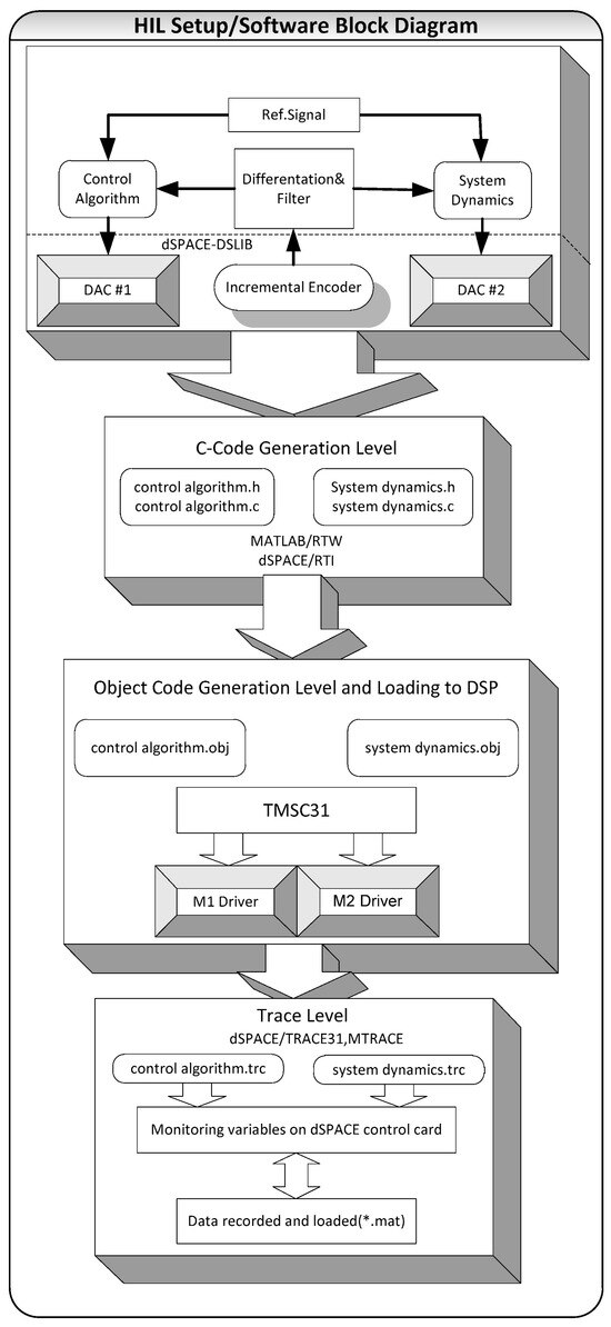
Figure 3.
Software architecture of the HIL system. Control algorithms, trajectory generation, and torque computation modules are implemented in MATLAB/Simulink, auto coded to C via Real-Time Workshop (RTW), and executed on the DSP card. Real-time monitoring and data logging are provided by TRACE32(*.mat; any mat file, #; count number).
4. Experiments Using HIL Setup
The proposed Hardware-in-the-Loop (HIL) setup (Figure 4) was used to implement and evaluate the developed nonlinear control strategies for direct-drive (DD) underactuated robotic systems. The platform employs two DD motors: one configured as a load simulator to replicate internal and external dynamic effects, and another acting as the joint actuator. The load simulator can generate disturbances such as interaction forces, structural vibrations, and other dynamic effects, while the actuator operates under these conditions.
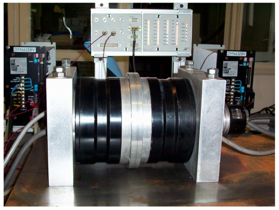
Figure 4.
HIL Setup.
A high-performance DSP controller executes real-time dynamic simulations and delivers the control inputs to the actuator, enabling performance evaluation under realistic and challenging scenarios. The system architecture, based on two DD actuators and a DSP control board, provides a flexible and cost-effective solution for both control performance evaluation and mechanical design validation. The developed graphical user interface (GUI) for real-time monitoring and control is shown in Figure 5. The complete HIL setup’s photographic block diagram is presented in Figure 6.
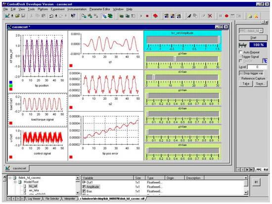
Figure 5.
HIL graphical user interface.
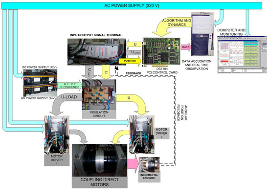
Figure 6.
HIL Setup photographic block diagram.
4.1. Control Signal Implementation in HIL Setup
The HIL setup generates ±10 V analog outputs through its DAC channels to deliver computed control signals to the motor drivers (Figure 7). Controllers designed in MATLAB/Simulink are compiled via Real-Time Workshop (RTW) and deployed to the DSP card, which applies the resulting control signal to the actuator in real time.

Figure 7.
Control signal implementation.
4.2. Derivation of Unmeasurable Variables in HIL Setup
Certain dynamic variables required for realistic simulation—such as angular velocities, accelerations, and flexible mode derivatives—are not directly measurable. These are derived from encoder-based angular position measurements using suitable filtering algorithms (Figure 8). The estimated variables are then used to calculate load torques, ensuring accurate emulation of system dynamics. The pseudo-code of the Kalman filtering algorithm used for this derivation is provided in Appendix A.
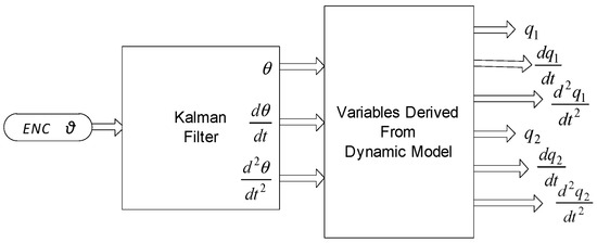
Figure 8.
Derivation of unmeasurable variables.
4.3. Load Torque Production in HIL Setup
Load torque generation is based on the dynamic model of the flexible-link arm (Equation (1)). Shape modes and their derivatives are computed using the derived expressions (Equation (14)) and block diagrams shown in Figure 9 and Figure 10. The resulting load torque profile is applied via the load simulator motor to reproduce the effects of structural flexibility and vibration on the actuator. The complete HIL experimental model is shown in Figure 11.

Figure 9.
Shape modes derivation block diagram.
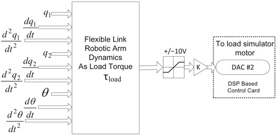
Figure 10.
Sample block diagram for load torque derivation.
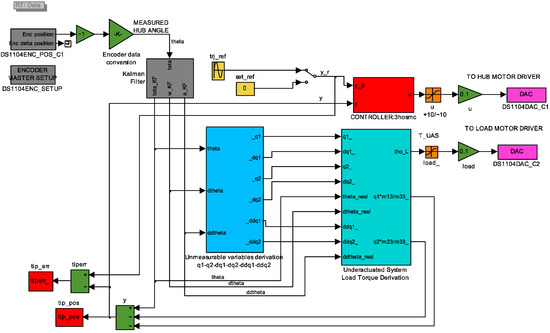
Figure 11.
Experimental model used in HIL Setup.
4.4. Experimental Data Analysis in HIL Setup
The flexible-link arm dynamics were tested under both set-point and trajectory tracking conditions, with experiments performed using classical Sliding Mode Control (SMC) and High-Order Sliding Mode Control (HOSMC) schemes of varying degrees.
- SMC Results—Figure 12, Figure 13, Figure 14 and Figure 15 show the set-point and trajectory tracking performance under SMC. While SMC achieved the desired motion, the response exhibited noticeable oscillations, tracking delays, and residual vibrations—especially under abrupt trajectory changes.
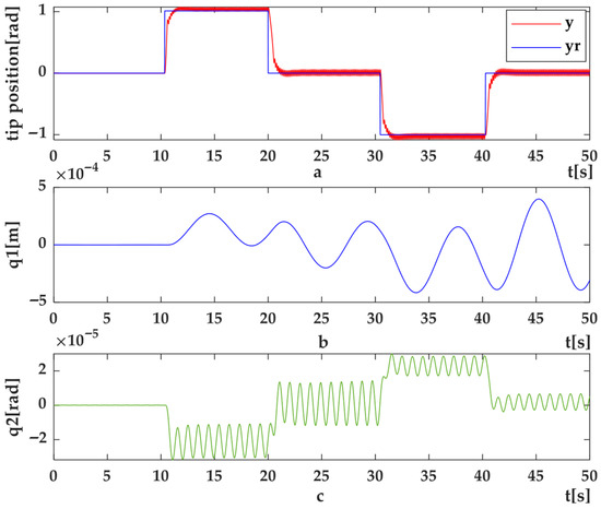 Figure 12. HIL Setup results for position control of flexible link arm using SMC method: (a) Set-point position (y) and desired position (yr) (b) shape modes, q1 (c) q2.
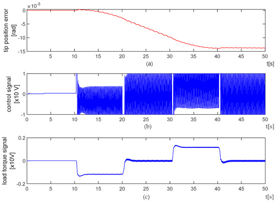 Figure 13. HIL Setup results for position control of flexible link arm using SMC method (a) position error (e); (b) control signal (u); (c) system dynamics as load torque (Mload).
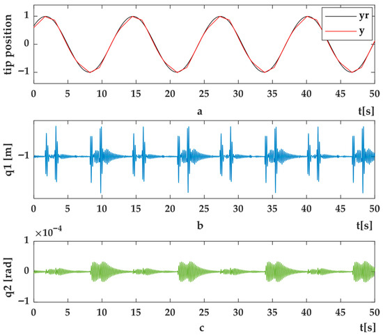 Figure 14. HIL Setup results for trajectory tracking control of flexible link arm using SMC methods (a) Trajectory tracking control (y) and desired trajectory (yr) (b) shape modes, q1 (c) q2.
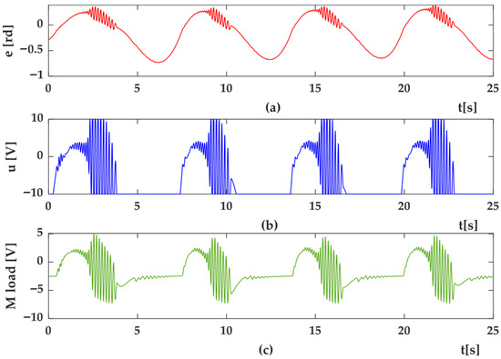 Figure 15. HIL Setup results for trajectory position control of flexible link arm using SMC method (a) position error (e) (b) control signal (u) (c) system dynamics as load torque (Mload).
 - HOSMC Results—Figure 16, Figure 17, Figure 18, Figure 19, Figure 20, Figure 21, Figure 22 and Figure 23 present the results for second and third degree HOSMC. Compared to SMC, HOSMC provided faster convergence (Figure 13a vs. Figure 17a), reduced residual vibration amplitudes (Figure 13b vs. Figure 17b), and smoother control signals.
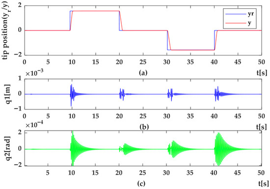 Figure 16. HIL Setup results for position control of flexible link arm using 2nd degree of HOSMC method (a) Targeting position (y) and desired position (yr) (b) shape modes, q1 (c) q2.
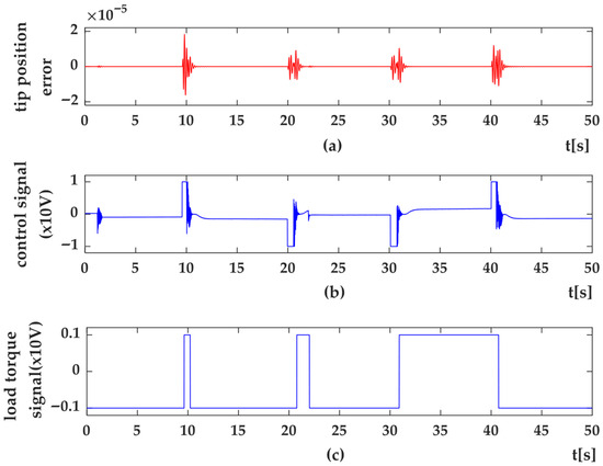 Figure 17. HIL Setup results for position control of flexible link arm using 2nd degree of HOSMC method (a) error (e); (b) control signal (u); (c) system dynamics as load torque (Msd).
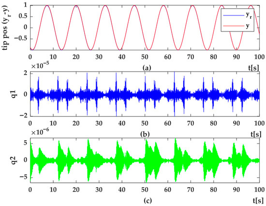 Figure 18. HIL Setup results for trajectory position control of flexible link using 2nd degree of HOSMC methods (a) Trajectory tracking control (y) and desired trajectory (yr) (b) shape modes, q1 (c) q2.
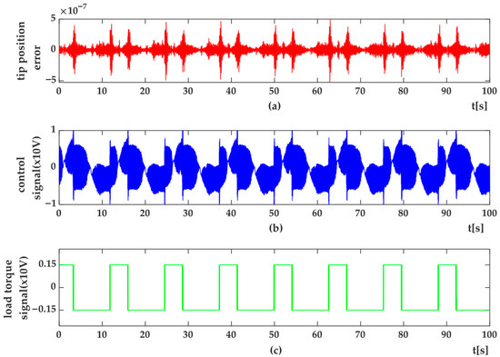 Figure 19. HIL Setup results for trajectory tracking control of flexible-link arm using 2nd degree of HOSMC method (a) trajectory tracking error (e) (b) control signal(u) (c) system dynamics as load torque (Msd).
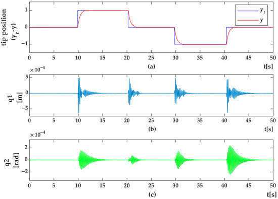 Figure 20. HIL Setup results for position control of flexible link arm using 3rd degree of HOSMC method (a) Targeting position (y) and desired position (yr) (b) shape modes, q1 (c) q2.
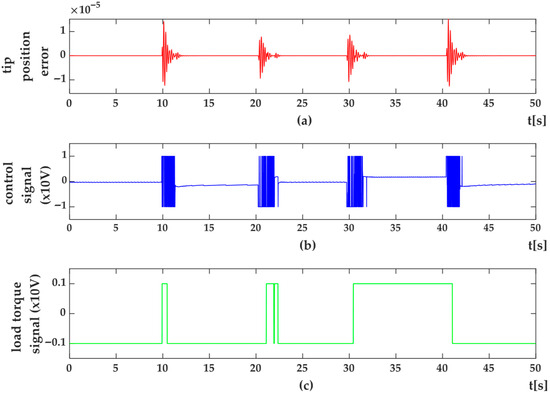 Figure 21. HIL Setup results for trajectory tracking control of flexible-link arm using 3rd degree of HOSMC method (a) error (e); (b) control signal (u); (c) system dynamics as load torque (Msd).
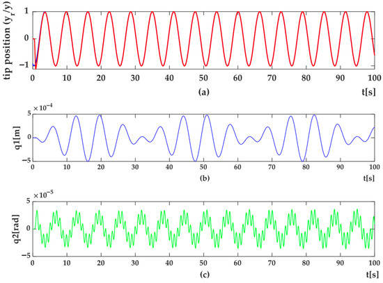 Figure 22. HIL Setup results for trajectory position control of flexible link using 3rd degree of HOSMC methods (a) Trajectory tracking control (y) and desired trajectory (yr) (b) shape modes, q1 (c) q2.
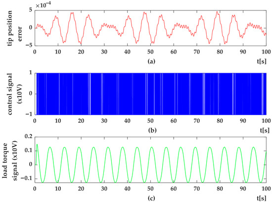 Figure 23. HIL Setup results for trajectory tracking control of flexible-link arm using 3rd degree of HOSMC method (a) trajectory tracking error (e); (b) control signal (u); (c) system dynamics as load torque (Msd).
Figure 18a shows the tip-point position response for a sinusoidal reference trajectory under the second-degree HOSMC method, while Figure 18b,c presents the corresponding variations in the first and second shape modes (q1q_1q1 and q2q_2q2). Figure 19 depicts the real-time position error, control signal, and load torque profiles obtained during the trajectory tracking experiments using the second-degree HOSMC approach.
The effect of torque pulsations on an electromechanical system is comparable to that of load disturbances; therefore, torque ripple rejection was considered as a performance criterion for the HOSMC methods. Fast Fourier Transform (FFT) analysis was applied to the acceleration output of the system under a ramp-type reference trajectory for each control algorithm. To establish a baseline, the torque spectrum of the 1-DOF flexible-link arm was evaluated, and the comparative torque harmonic spectra for SMC and HOSMC are presented in Figure 24. The third-order HOSMC achieved superior suppression of torque ripple, which is attributed to the elimination of chattering in the control input.
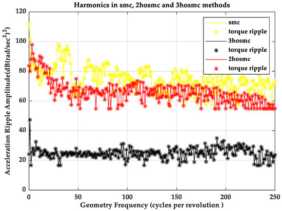
Figure 24.
Torque Ripple Suppression effects of the SMS, 2-HOSMC and 3-HOSMC methods.
- Performance Comparison
- Convergence and Tracking—HOSMC achieved shorter settling times and improved tracking accuracy compared to SMC, particularly for smooth or moderate-speed trajectories.
- Vibration Suppression—The amplitude of flexible modes was significantly reduced under HOSMC, demonstrating effective damping of high-frequency oscillations.
- Control Smoothness—HOSMC reduced chattering and produced smoother torque outputs, lowering mechanical stress on actuators.
- Limitations—In high-frequency, high-acceleration trajectories, HOSMC’s damping effect occasionally reduced peak amplitude tracking, introducing a small steady-state error in rapid transitions.
These results confirm that the HOSMC approach offers a better compromise between robustness, vibration suppression, and control smoothness than classical SMC, making it more suitable for precision-critical flexible-link robotic applications.
5. Conclusions
This paper presented a Hardware-in-the-Loop (HIL) simulation case study on the application of High-Order Sliding Mode Control (HOSMC) to a flexible-link robotic arm. The developed HIL platform integrates physical direct-drive actuators and sensors with a real-time MATLAB/Simulink simulation environment, enabling rigorous testing of advanced nonlinear control algorithms under realistic operating conditions without the need for a full-scale prototype.
Experimental results demonstrated that HOSMC outperforms classical Sliding Mode Control (SMC) in several aspects. Specifically, HOSMC achieved faster convergence, improved tracking accuracy, reduced residual vibrations, and generated smoother control signals—thereby decreasing actuator stress. The ability of HOSMC to suppress high-frequency oscillations makes it particularly suitable for precision-critical applications involving flexible structures.
However, the study also identified limitations. For high-frequency, high-acceleration trajectories, the inherent damping effect of HOSMC occasionally reduced peak tracking performance, introducing a small steady-state error. These findings suggest that while HOSMC is a robust and vibration-suppressing control strategy, further tuning or adaptive approaches may be required to improve responsiveness in fast-changing reference conditions.
Overall, the proposed HIL setup proved to be a cost-effective and flexible test environment for validating advanced control strategies in flexible-link robotic systems. Future work will focus on extending the platform to multi-link flexible manipulators and a limitation of the present study is that under high-speed or high-frequency trajectories, the damping action of the high-order sliding mode controllers can attenuate peak amplitudes, which may introduce small steady-state errors during rapid transitions. Addressing these limitations will be an important focus of future work. Adaptive or hybrid HOSMC schemes could be developed to maintain robustness while improving tracking performance in high-frequency operating regimes.
Author Contributions
Methodology, A.A.; Software, D.K.S.; Investigation, D.K.S.; Writing—original draft, A.A.; Writing—review & editing, A.A. and D.K.S.; Visualization, D.K.S.; Supervision, A.A.; Project administration, D.K.S. All authors have read and agreed to the published version of the manuscript.
Funding
This research received no external funding.
Institutional Review Board Statement
Not applicable.
Informed Consent Statement
Not applicable.
Data Availability Statement
The original contributions presented in the study are included in the article, and further inquiries can be directed to the corresponding author.
Acknowledgments
This publication was supported by the Scientific Projects Coordination Unit of Istanbul Yeni Yüzyıl University.
Conflicts of Interest
The authors declare no conflicts of interest.
Appendix A
| Algorithm A1: Discrete-Time Kalman Filter |
| Initialization: x̂(θ) ← xθ # Initial state estimate P(θ) ← Pθ # Initial error covariance Define Q, R # Process and measurement noise covariance Define A, B, C, D # State-space model matrices For each time step k do: 1: Prediction step: x̂−(k) = A · x̂(k − 1) + B · u(k − 1) # State prediction P−(k) = A · P(k − 1) · Aᵀ + Q # Covariance prediction 2: Measurement update: K(k) = P−(k) · Cᵀ · (C · P−(k) · Cᵀ + R)−1 # Kalman gain ŷ(k) = C · x̂−(k) + D · u(k) # Predicted measurement e(k) = y_meas(k) − ŷ(k) # Innovation (residual) x̂(k) = x̂−(k) + K(k) · e(k) # State correction P(k) = (I − K(k) · C) · P−(k) # Covariance correction Outputs: x̂(k) # Estimated states (e.g., θ, ω, a) ŷ(k) # Predicted measurement K(k) # Kalman gain |
References
- Asada, H.; Youcef-Toumi, K. Direct-Drive Robots: Theory and Practice; MIT Press: Cambridge, MA, USA, 1987. [Google Scholar]
- Simon, D.L.; Bianco, S.J.; Horning, M.A.; Saus, J.R.; Amthor, A.E.; Sachs-Wetstone, J.J. Real-Time Hardware-in-the-Loop Evaluation of a Partially Turboelectric Propulsion Control Design; NASA Technical Memorandum NASA/TM–20230010194. In Proceedings of the AIAA Aviation Electrified Aircraft Technology Symposium, San Diego, CA, USA, 12–16 June 2023. [Google Scholar]
- Düzgün, M.T.; Heusch, C.; Krysmon, S.; Dönitz, C.; Lee, S.-Y.; Andert, J.; Pischinger, S. Dynamic Closed-Loop Validation of a Hardware-in-the-Loop Testbench for Parallel Hybrid Electric Vehicles. World Electr. Veh. J. 2025, 16, 273. [Google Scholar] [CrossRef]
- Wang, Z.; Zha, J.; Wang, J. Autonomous vehicle trajectory following: A flatness model predictive control approach with hardware-in-the-loop verification. IEEE Trans. Intell. Transp. Syst. 2021, 22, 5613–5623. [Google Scholar] [CrossRef]
- Moreira, M.L.; Singh, R.; Gomez-Badillo, A.; Albakri, B.; Venugopal, V.; Park, Y.; Cetin, S. Hardware-in-the-Loop Controller Testing and Visualization of an Industrial Gantry. Front. Mech. Eng. 2025, 10, 1451042. [Google Scholar] [CrossRef]
- Tran, D.T.; Nguyen, T.D.; Tran, M.K.; Ahn, K.K. Development of a Hardware-in-the-Loop Platform for a Teleoperation Flexibility Robotic System. Appl. Sci. 2024, 14, 2207. [Google Scholar] [CrossRef]
- Martin, A. Dynamic load emulation in hardware-in-the-loop simulation of robot manipulators. IEEE Trans. Ind. Electron. 2011, 58, 2980–2988. [Google Scholar] [CrossRef]
- Waszniowski, L.; Hanzálek, Z.; Doubrava, J. Aircraft control system validation via hardware-in-the-loop simulation. J. Aircr. 2011, 48, 1466–1468. [Google Scholar] [CrossRef]
- Viehweider, A.; Lauss, G.; Felix, L. Stabilization of power hardware-in-the-loop simulations of electric energy systems. Simul. Model. Pract. Theory 2011, 19, 1699–1708. [Google Scholar] [CrossRef]
- Gaspar, J.F.; Pinheiro, R.F.; Mendes, M.J.G.C.; Kamarlouei, M.; Soares, C.G. Review on hardware-in-the-loop simulation of wave energy converters and power take-offs. Renew. Sustain. Energy Rev. 2024, 191, 114144. [Google Scholar] [CrossRef]
- Mazzoleni, N.; Bryant, M. Hardware-in-the-loop dynamic load emulation of robotic systems actuated by fluidic artificial muscles. J. Intell. Mater. Syst. Struct. 2024, 35, 945–959. [Google Scholar] [CrossRef]
- Li, T.; Wang, Y.; Yang, Z.; Yang, T.; Deng, S.; Liang, B.; Du, B. Research on Full Hardware-in-loop Ground Simulation Test Method of Space Manipulator. In Proceedings of the 2022 Chinese Intelligent Systems Conference, Beijing, China, 15–16 October 2022; Springer: Singapore, 2022; pp. 703–710. [Google Scholar] [CrossRef]
- Malekzadeh, M.; Rezayati, M.; Saboohi, M. Hardware-in-the-loop attitude control via a high-order sliding mode controller/observer. Proc. Inst. Mech. Eng. Part G J. Aerosp. Eng. 2018, 232, 1944–1960. [Google Scholar] [CrossRef]
- Rezkallah, M.; Hamadi, A.; Chandra, A.; Singh, B. Real-time HIL implementation of sliding mode control for standalone system based on PV array without using dumpload. IEEE Trans. Sustain. Energy 2015, 6, 1389–1398. [Google Scholar] [CrossRef]
- Bayrakceken, M.K.; Arisoy, A. An Educational Setup for Nonlinear Control Systems: Enhancing the motivation and learning in a targeted curriculum by experimental practices. IEEE Control Syst. Mag. 2013, 33, 64–81. [Google Scholar]
- Or, K.; Wu, K.; Nakano, K.; Ikeda, M.; Ando, M.; Kuniyoshi, Y.; Niiyama, R. Curriculum-reinforcement learning on simulation platform of tendon-driven high-degree of freedom underactuated manipulator. Front. Robot. AI 2023, 10, 1066518. [Google Scholar] [CrossRef]
- Lochan, K.; Roy, B.K.; Subudhi, B. A review on two-link flexible manipulators. Annu. Rev. Control 2016, 42, 346–367. [Google Scholar] [CrossRef]
- Sayahkarajy, M.; Mohamed, Z.; Faudzi, A.A.M. Review of modelling and control of flexible-link manipulators. Proc. Inst. Mech. Eng. Part I J. Syst. Control Eng. 2016, 230, 861–873. [Google Scholar] [CrossRef]
- Geniele, H.; Patel, R.V.; Khorasani, K. End-point control of a flexible-link manipulator: An experimental study. IEEE Trans. Control Syst. Technol. 1997, 5, 556–570. [Google Scholar] [CrossRef]
- Karim, M.I.; Hashim, A.A.A.; Abdul Ghani, N.M. Control of Double Link Flexible Robotic Manipulator System. J. Eur. Des Systèmes Autom. 2022, 55, 755–762. [Google Scholar] [CrossRef]
- Jing, F.; Ma, C.; Wang, F.; Xie, M.; Feng, X.; Fan, X.; Wang, X.; Liu, P. Tracking control of a flexible-link manipulator based on an improved barrier function adaptive sliding mode. Asian J. Control 2024, 26, 2916–2932. [Google Scholar] [CrossRef]
- Zhao, Z.; Chang, H.; Wu, C. Adaptive fuzzy command filtered tracking control for flexible robotic arm with input dead-zone. Appl. Sci. 2023, 13, 10812. [Google Scholar] [CrossRef]
- Gambhire, S.J.; Kishore, D.R.; Londhe, P.S.; Pawar, S.N. Review of sliding mode based control techniques for control system applications. Int. J. Dyn. Control 2021, 9, 363–378. [Google Scholar] [CrossRef]
- Zaihidee, F.M.; Mekhilef, S.; Mubin, M. Robust speed control of pmsm using sliding mode control (smc)—A review. Energies 2019, 12, 1669. [Google Scholar] [CrossRef]
- Karami-Mollaee, A.; Barambones, O. Higher Order Sliding Mode Control of MIMO Induction Motors: A New Adaptive Approach. Mathematics 2023, 11, 4558. [Google Scholar] [CrossRef]
- Halimi, H.; Elgarouaz, M.; Lazrak, L.; El Daoudi, S. High-order sliding mode control with hyperbolic evaluation function for improving performances of a squirrel-cage induction motor fed by a two-level inverter. Int. J. Dyn. Control 2024, 12, 2929–2943. [Google Scholar] [CrossRef]
- Zhao, Z.; Cao, D.; Yang, J.; Wang, H. High-order sliding mode observer-based trajectory tracking control for a quadrotor UAV with uncertain dynamics. Nonlinear Dyn. 2020, 102, 2583–2596. [Google Scholar] [CrossRef]
- Kshetrimayum, L.; Seneviratne, L.; Hussain, I. Adaptive Global Super-Twisting Sliding Mode Control for Trajectory Tracking of Two-Link Flexible Manipulators. IEEE Access 2025, 13, 61876–61889. [Google Scholar] [CrossRef]
- Mhmood, A.H.; Mahyuddin, M.N. H∞ Sliding Mode Control: A Recent Review of Applications and Design Methods. IEEE Access 2025, 13, 136687–136715. [Google Scholar] [CrossRef]
- Tarla, L.B.; Bakhti, M.; Idrissi, B.B. Robustifying hierarchical sliding mode control for active vibration suppression of a flexible manipulator using integral sliding mode control. Int. J. Intell. Robot. Appl. 2023, 7, 641–651. [Google Scholar] [CrossRef]
Disclaimer/Publisher’s Note: The statements, opinions and data contained in all publications are solely those of the individual author(s) and contributor(s) and not of MDPI and/or the editor(s). MDPI and/or the editor(s) disclaim responsibility for any injury to people or property resulting from any ideas, methods, instructions or products referred to in the content. |
© 2025 by the authors. Licensee MDPI, Basel, Switzerland. This article is an open access article distributed under the terms and conditions of the Creative Commons Attribution (CC BY) license (https://creativecommons.org/licenses/by/4.0/).