Combating the Counterfeit: A Review on Hardware-Based Anticounterfeiting Technologies
Abstract
1. Introduction
- Taxonomic Framework: Establishment of a robust classification system, categorizing and defining diverse methodologies based on their underlying principles and functionalities.
- Comparative Analysis: Rigorous evaluation of prominent technologies, appraising their strengths and weaknesses across key metrics such as security level, cost-effectiveness, implementation ease, and scalability, empowering stakeholders to make informed choices based on their specific needs.
- Practicality and Integration in the System: Discussion on the practicalities of implementation, crucial factors to consider when selecting hardware-based solutions. This includes product type, target audience, and integration with existing systems, ensuring the chosen technology seamlessly fits within existing infrastructure.
- Real-World Impact: To showcase the effectiveness of hardware-based solutions, certain case studies and real-world applications from diverse industries have been discussed. These examples demonstrate the tangible impact of these technologies in combating counterfeiting across various domains.
- Unclonability/Security Level, which includes the difficulty in replication, robustness of attack, randomness/uniqueness.
- Identification states/data capacity, which involves calculation of the number of unique identifiers.
- Readability/Reliability, which is associated with the read range and speed, accuracy, error rate, orientation with respect to the reader.
- Cost effectiveness, which includes the tag and the reader/overall deployment cost.
- Integration and Compatibility with the current systems, and the associated environmental impact.
2. Electronic Anticounterfeiting Techniques
2.1. Near Field Communication—NFC
2.2. Magnetic Stripes
- Simplicity: Require minimal infrastructure to read and write data, making them cost-effective and accessible.
- Durability: Resistant to wear and tear, lasting for years under regular use.
- Versatility: Can be integrated into various objects, from cards to packaging, offering broad applicability.
- Magnetic material: The core of the strip is a thin layer of ferromagnetic material, typically iron oxide, capable of storing data encoded as a series of magnetized zones. This standard tape strip contains three magnetic tracks, containing magnetic resins that are used to store the card’s data, in encoded format [8].
- Substrate: The magnetic material is embedded within a flexible substrate, usually polyvinyl chloride (PVC), for protection and handling.
- Encoding/Reading Head: A specialized device which writes/reads data by magnetizing or sensing the magnetic fields of the zones. These heads can be integrated into card readers, point-of-sale terminals, or even handheld verification devices.
2.3. Contact Chips—Smart Cards
- Memory cards: These category of smart card incorporates a non-volatile memory chip embedded within its structure. This memory component facilitates both data reading and writing operations embedded within a pre-programmed logic circuit etched directly onto the chip during the manufacturing process. This embedded logic circuit safeguards the stored data through a security mechanism that typically leverages access permission protocols. Consequently, these cards offer exclusively secure data storage functionalities.
- Microprocessor cards: This category of the smart card integrates a microprocessor, granting it computational capabilities akin to those of portable slow computing devices. Consequently, these smart cards possess the ability to process, store, and secure information through the utilization of sophisticated cryptographic algorithms.
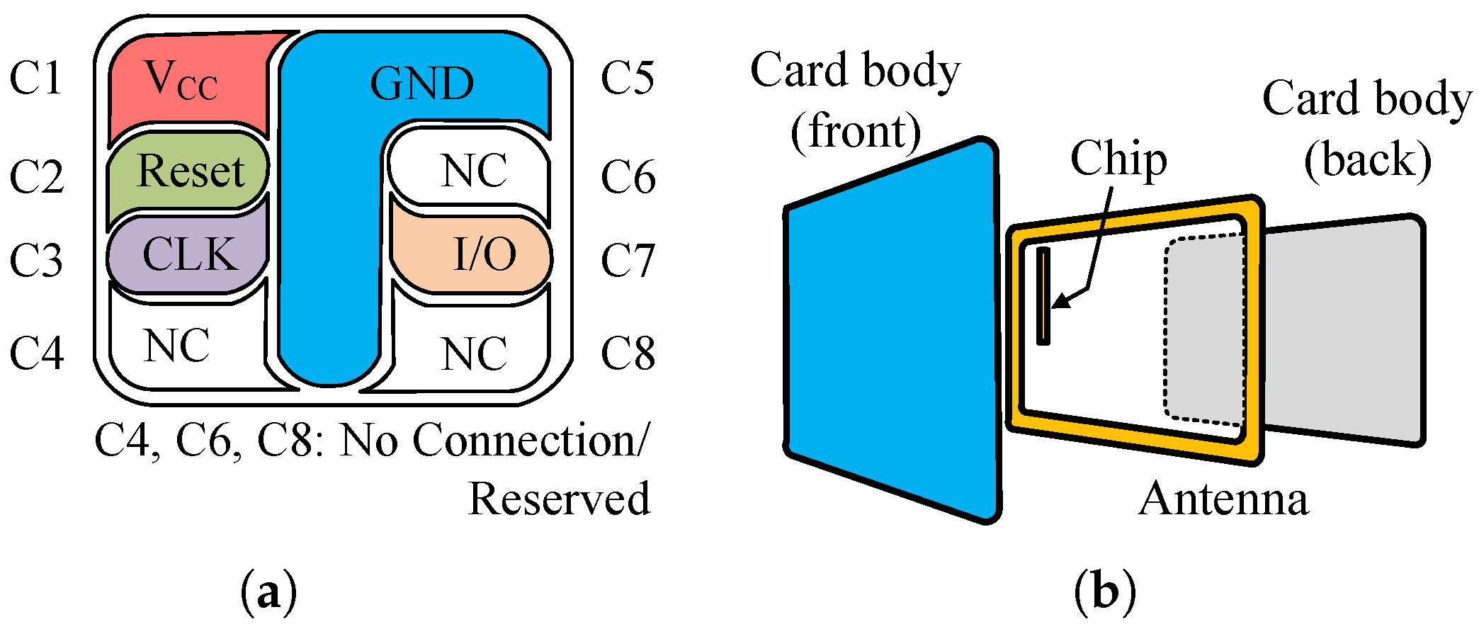
- Contact cards: Contact card communicates utilizing an eight-pin micromodule to establish a physical connection with the card reader, as shown in Figure 1a. Each of the five designated pins serves a specific function: VCC (+5 volts − DC) supplies power, reset initializes the module, clock regulates timing, ground provides a reference potential, and the input/output (I/O) pin facilitates data exchange.
- Contactless cards: As illustrated in Figure 1b, contactless smart cards rely on antennas with an approximate 10-cm range to establish communication with readers. These memory chip devices, physically comparable to credit cards, acquire power and exchange information with the reader through an Radio Frequency (RF) field generated by the reader module. Contactless smart cards are commonly utilized for employee identification badges in building access systems of large organizations.
- Combination cards: Multipurpose combination smart cards represent a strategic integration of contact and contactless technologies. These hybrid cards incorporate an eight-pin contact interface for communication with card readers employing physical connections, and additionally feature an antenna that facilitates wireless data exchange with RF readers. This dual functionality expands the application scope of the card, catering to a wider range of use cases.
2.4. Electronic Seal
- Non-duplicability: The electronic seal must resist replication, ensuring its uniqueness.
- Reliability: The seal should be designed to prevent resealing after being opened, and the act of opening should be readily discernible.
- Verifiability: An operator must be able to readily confirm both the authenticity and integrity of the seal, either through visual inspection or by employing a dedicated device.
2.5. Radio Frequency Identification—RFID
- Automated inventory management: Streamlining stock control and reducing manual intervention.
- Automated quality control: Enabling real-time monitoring and ensuring product integrity.
- Access control: Enhancing security by granting or restricting entry based on tag identification.
- Payment systems: Facilitating contactless and secure transactions.
- General security applications: Providing additional layers of security and preventing unauthorized access.
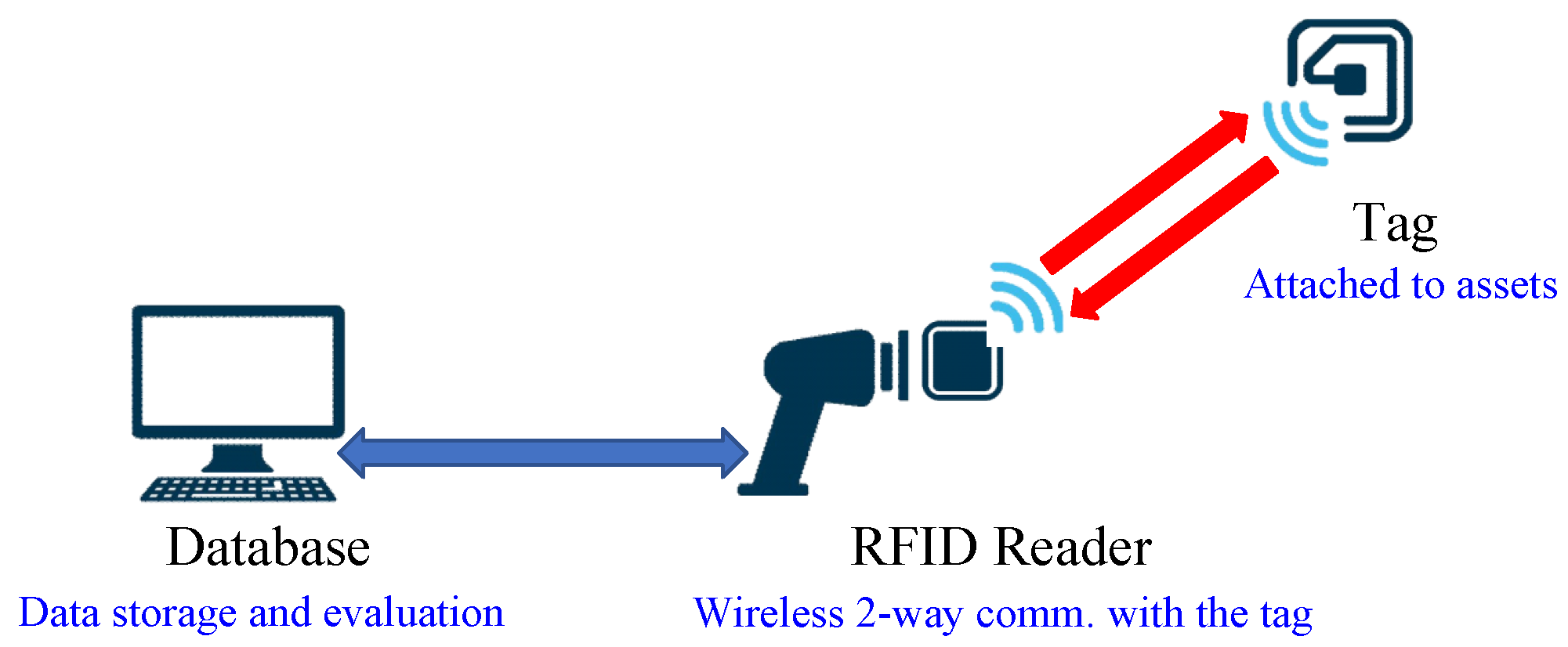
- Tags: Attached to objects, these contain an antenna and/ or a microchip storing product data such as unique identifiers or informational website URLs. Security against reproduction and tampering relies on:Communication protocols: Governing data exchange between tags and readers.Information protection methods: Securing tag data through codes, passwords, or encryption algorithms.
- Readers: Specific to the utilized tag type, these devices query tags, receive response information, and transmit it to a data processing system.
- Data Processing System: Connected to readers via the internet, this system utilizes tag identification codes to access and manage relevant object information.
2.5.1. Passive Tags
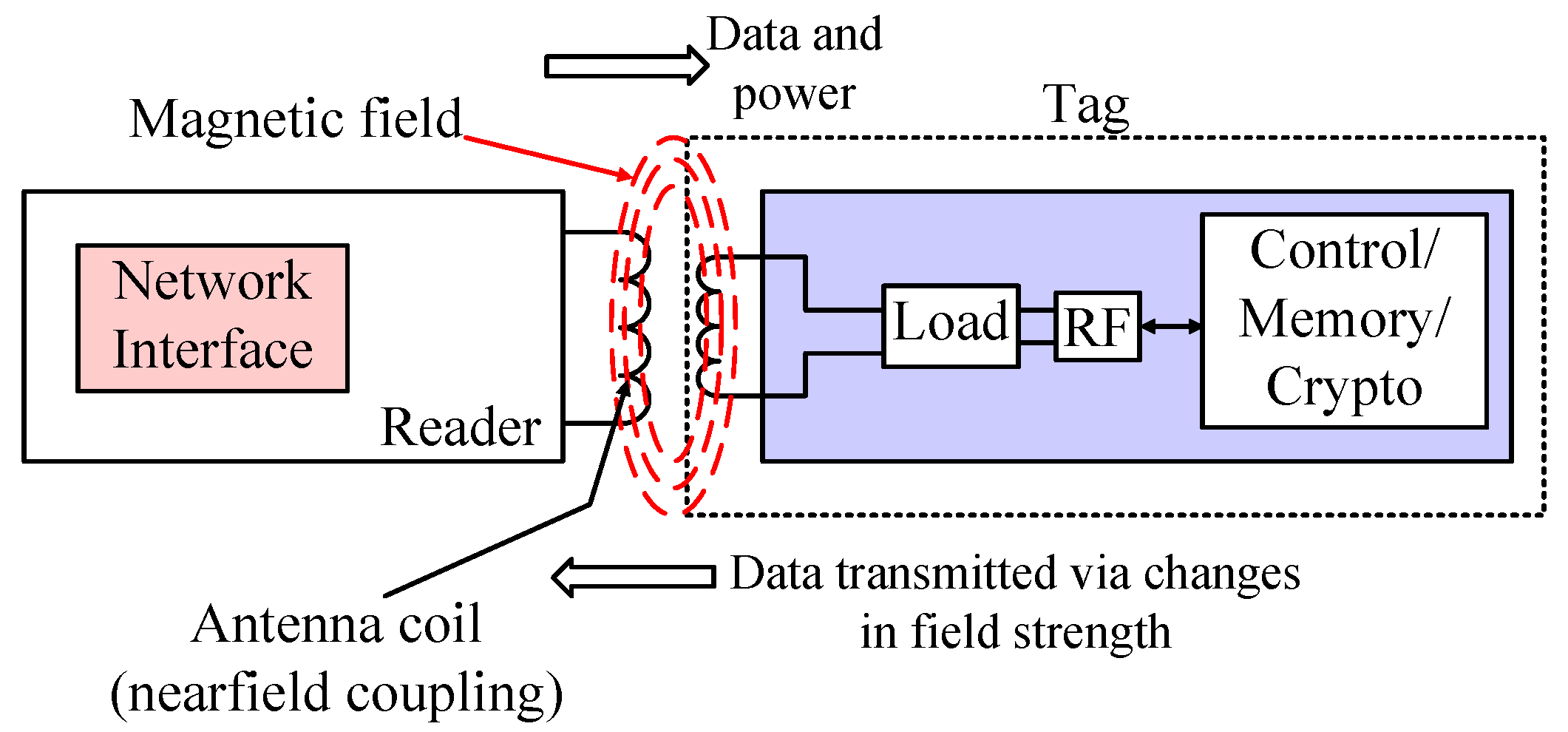
- Near-Field Coupling: Within the near field region, the prevailing characteristic of the electromagnetic field is its reactive nature. This signifies that the electric and magnetic fields are spatially orthogonal (perpendicular) and exhibit quasi-static behavior, meaning they experience minimal change over time. The dominant field, electric with a dipole antenna, or magnetic with a coil antenna, depends upon the specific antenna type employed. Most near-field tags utilize the magnetic field to achieve inductive coupling with the tag’s coil, following Faraday’s principle of magnetic induction (illustrated in Figure 5). In essence, current flowing through the reader’s coil establishes a magnetic field in its vicinity. This field, in turn, induces a small current within the coil of a nearby tag.The interaction between a reader and a tag leverages a technique known as load modulation [32]. This method works on the principle of mutual inductance, where a change in current within the tag’s coil induces a corresponding, albeit smaller, current variation in the reader’s coil. The reader detects these subtle variations. To achieve this, the tag modulates the current by deliberately altering the load presented by its antenna coil. This deliberate manipulation of the load underlies the term load modulation. Owing to its inherent simplicity, inductive coupling was the initial technology embraced for passive RFID systems due to its ease of implementation.As the phenomenon is a nearfield one, such tags are restricted to the use of low carrier frequencies, being mostly restricted at 128 kHz (low-frequency, LF) and 13.56 MHz (high-frequency, HF). This limitation is exemplified by the operational boundary distances, which are significantly shorter for higher frequencies: 372 m for 128 kHz and 3.5 m for 13.56 MHz. An inherent drawback of near-field tags is their inherently low bandwidth, which translates to a correspondingly low data rate [33].
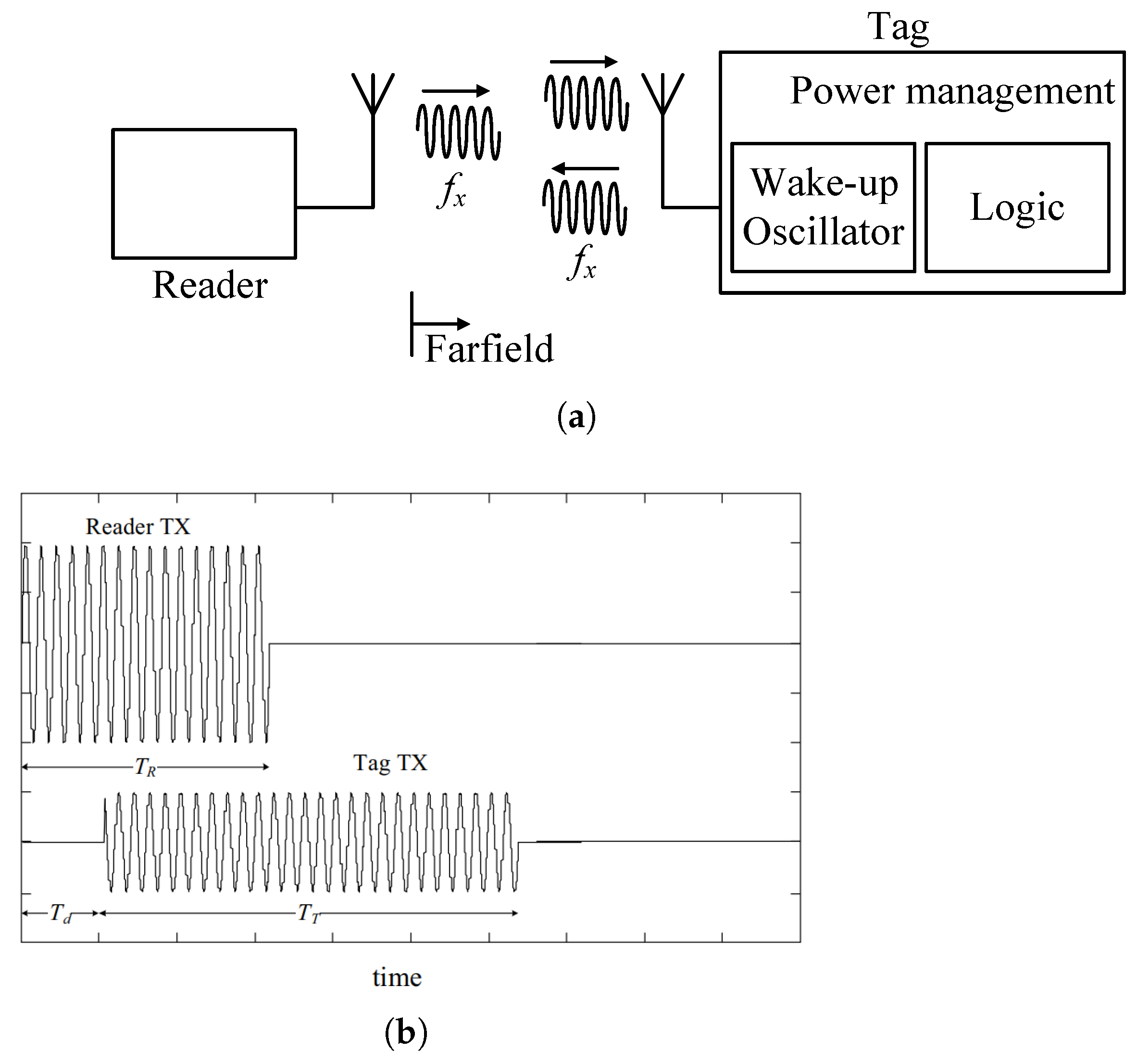
- FarField Coupling: In contrast to the near-field region, the EM field within the far-field exhibits a radiative nature. In this regime, coupling involves the capture of EM energy at a tag’s antenna as a potential difference. However, a portion of the incident energy reflects back due to an impedance mismatch between the antenna and the load circuit. This mismatch, or deliberate alterations to it, can be exploited to vary the amount of reflected energy, a technique commonly known as backscattering [34] (illustrated in Figure 6). Such a methodology serves as the foundational principle for communication in far-field tags.Far-field coupling is the preferred method for long-range (5–20 m) RFID applications, as it is not subject to the restrictive field boundaries encountered in near-field systems. Far-field tags typically operate within the 860–960 MHz Ultra-High Frequency (UHF) band or the 2.45 GHz Microwave band.
2.5.2. Active Tags
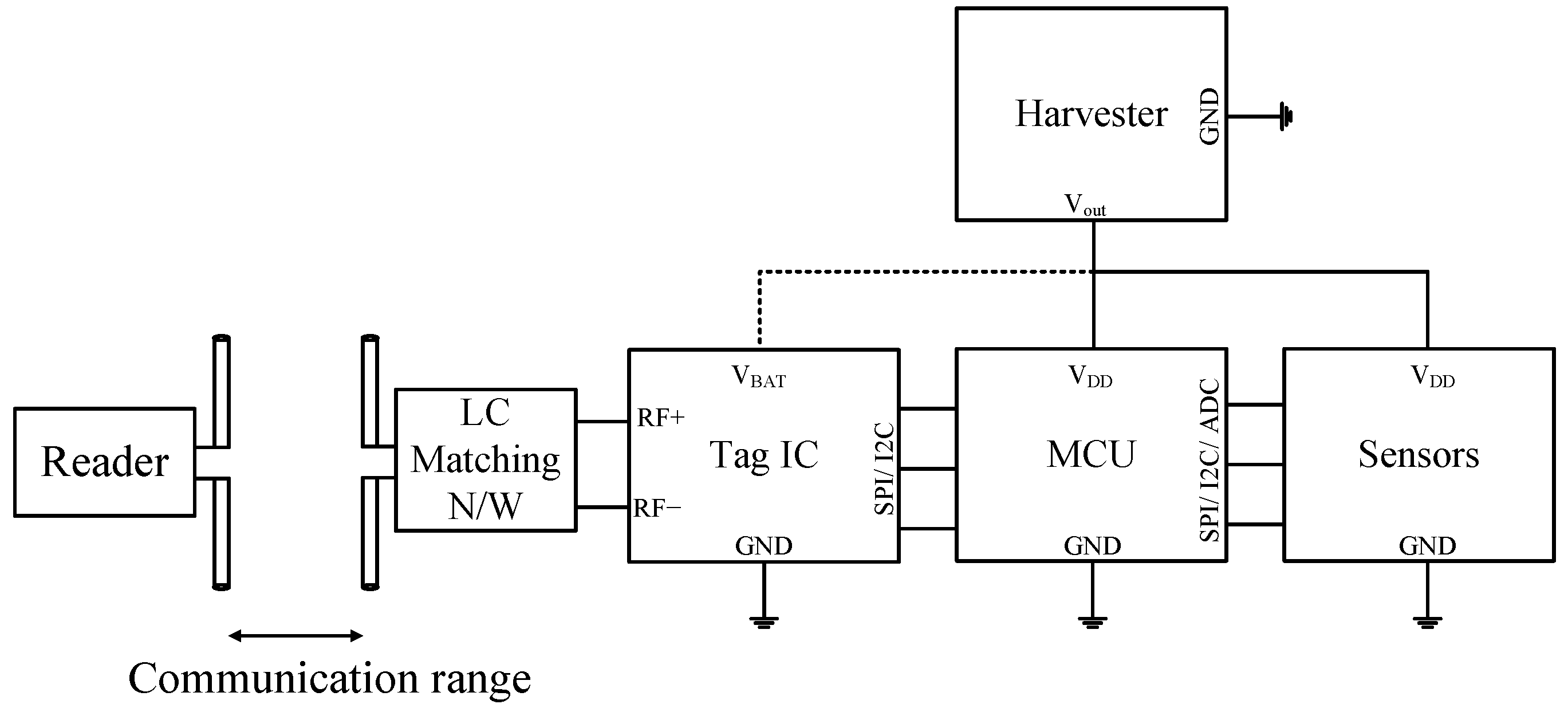
- Transponders: Functioning similarly to passive RFID systems, active transponder tags operate in a reader-initiated mode. The reader transmits a signal, prompting the active transponder to respond with a corresponding signal containing the encoded data. This interrogation-response mechanism fosters efficient battery utilization for the transponder. When out of the reader’s range, the transponder remains inactive, thus preserving battery life. Active RFID tags utilize a low-power LC-oscillator (depicted in Figure 7) as a wakeup radio. This oscillator is specifically designed to function in the weak inversion region (subthreshold) to minimize power consumption. The oscillator operates near its oscillation threshold, and an incoming radio signal received by the antenna provides the necessary signal to achieve a stable oscillating state. Figure 8 illustrates how the received RF signal triggers the wakeup radio receiver, prompting the tag to transmit a response signal back (backscattered) to the reader on the same frequency, with the relevant timing diagram.Owing to this advantage, active transponder tags are prevalent in applications demanding high security, such as access control systems, and in scenarios requiring real-time data exchange, like toll booth payment systems.
- Beacons: Active beacon tags deviate from the reader-initiated approach employed in passive and active transponder RFID systems. As their designation implies, beacon tags function autonomously, periodically transmitting their unique data at intervals typically ranging from 3 to 5 s. While active beacon tags boast read ranges of hundreds of meters, their transmission power can be strategically adjusted to optimize battery life, achieving a practical range of around 100 m.
2.5.3. Battery Assisted Passive (BAP) Tags
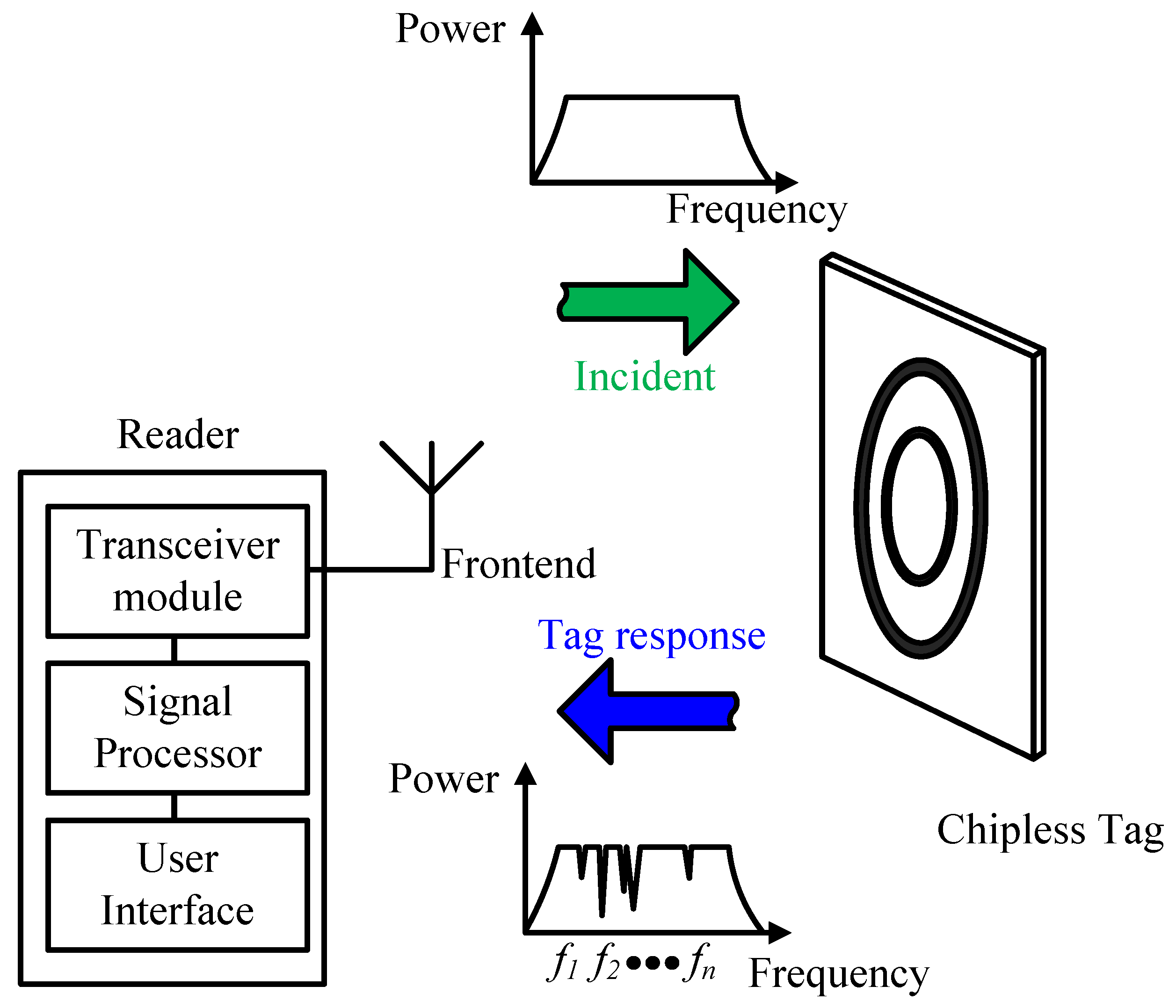
2.5.4. Chipless RFID
- Order volume and functionality: The cost of RFID tags varies significantly based on the number of tags ordered and the specific functions they need to perform.
- Item cost: The value of the item being tagged influences the required security level, which in turn affects the tag’s price. For example, a high-value item like a luxury watch requires a more secure and expensive tag than a standard item like a book.
- Deployment environment: The environment where the tag will be used also affects its cost. Tags deployed in harsh environments, such as for asset management in a yard or livestock tracking, must be more durable and rugged, which increases their price.
2.5.5. Physically Unclonable Functions
- Optical vs. Silicon-based PUFs: Although silicon-based PUFs are widely used, they can be vulnerable to modeling attacks and often lack reliability [53,54]. Optical PUFs offer a promising alternative, providing high complexity and accessible readout. This is particularly true for chemically engineered optical PUFs, which can be highly robust and efficient [55,56,57].
- Fluorescent Taggants in Optical PUFs: Optical PUFs use various fluorescent taggants, including quantum dots, nanocrystals, organic dyes, and carbon dots [58,59,60,61]. Recently, silicon quantum dots have also emerged as a viable option [62]. However, semiconducting polymer nanoparticles (SPNs) are a strong alternative, surpassing most fluorescent materials in brightness and photostability [63,64]. SPNs have been shown to be over 30 times brighter than inorganic quantum dots and antibody-dye conjugates [65] and are more photostable than typical fluorescent dyes.
- Hybrid PUFs: Hybrid PUFs enhance security by combining physical randomness with a more robust digital system, often an RFID chip [66,67]. This makes them significantly more secure than static identifiers like barcodes, as it is impossible to clone both the physical structure and the cryptographic response simultaneously.
- Exceptional Security and Unclonability
- Robustness to Environmental Variations
- Enhanced Traceability and Supply Chain Security
- Complexity and Implementation Costs
- Dependency on reader
- Potential for Modeling Attacks
- Optimal tag programming performance necessitates the appropriate attachment of the tag to the product. This selection process requires careful consideration of two key factors: antenna orientation and the material’s skin depth at the tag’s operational frequency.
- Following product purchase or consumption, the product-bound tag should be deactivated to mitigate the risk of unauthorized reuse by counterfeiters.
- An efficient mechanism for tag programming and database synchronization is crucial to ensure seamless product tracking within the manufacturing line. However, incomplete or erroneous tag programming, potentially caused by inadequate configuration of RFID equipment (encompassing both hardware and software control parameters), can compromise the uniqueness of tag data and consequently, the integrity of the product’s provenance.
- A robust exception-handling mechanism is necessary to identify and manage products with defective tags, including those with duplicate or incomplete programming. This mechanism should facilitate the segregation of such products for either rework (if cost-effective) or disposal.
- Optimization of product transfer speed on a manufacturing or packaging line must balance production throughput with reliable RFID tag programming.
3. Mechanical Anticounterfeiting Techniques
3.1. Security Films
- Overprinting: Security elements are strategically positioned for optimal protection within the security film’s structure. This typically involves placement on the reverse side (interior) of the film or within the intermediary layer between the adhesive and the film itself. This approach safeguards these elements from potential damage or tampering attempts [86]. Screen printing, or flexographic printing techniques are commonly employed for their application.Screen printing operates on the principle of selective ink transfer through a mesh screen. Ink permeates the open areas of the screen, corresponding to the desired graphic elements, while the non-printing areas are rendered impermeable by a blocking stencil. This technique can be employed in color film printing using a three-step process: application of a glossy bottom layer, followed by a white base, and finally the addition of specific colors [87]. The factors which affect the printing include (but are not limited to) oil ink, paper, ink knife, cleanliness of the printer heads, speed of screen printing, scraper, the orientation/way of placing paper, tension of network board, pressure adjusting of scraper, angle adjusting of scraper, and human errors [88].There has also been substantial research for ecologically sustainable alternatives, which includes the use of starch as the printing ink in security films [89,90,91,92], to name a few. Although starch is a bio-compatible, cheap, and renewable solution, the disadvantages that limit their usage as packaging films: moisture sensitivity and low mechanical strength and stability.
- Embedding through binding: This technique is primarily utilized to safeguard photographs and printed personal identification data within passports. To deter tampering attempts, the security film is seamlessly integrated into the passport’s binding during construction. This integration process results in a narrow extension of the film material onto the subsequent page at the document’s rear, creating a tamper-evident margin [86].
3.2. Laser Engravings
- Annealing: This process, also known as laser surface stamping, utilizes a targeted laser beam to permanently mark ferrous metals and titanium. The laser induces localized heating on the surface, triggering a controlled oxidation reaction beneath. This selective oxidation results in a permanent discoloration of the metal, replicating the desired marking design [102].
3.3. Seals
- Unique Identification: Each seal possesses a distinct identifier, allowing for its unambiguous verification.
- High Tamper Evident Security: Seals are designed to be exceedingly difficult to replicate, offering a clear indication of tampering if any attempt is made.
- Enhanced Security: By virtue of their unique identification and tamper-evident nature, seals contribute significantly to the overall security of a package, over which they are the usual choice.
- Limited Tamper History: Unlike some electronic seals, physical seals cannot record the specific time or location of a tampering event. This may limit the ability to pinpoint the exact time and place of a breach.
- Passive Security: Physical seals lack the ability to actively monitor their own integrity. Therefore, unlike electronic seals that can trigger alarms upon tampering, physical seals rely solely on visual inspection for detection.
3.4. Labels
- Fabric based labels: Fabric labels exhibit remarkable versatility by integrating with various security features, resulting in a spectrum of label complexity. The most basic labels serve the primary function of displaying product information and identification codes, typically barcodes. As complexity increases, labels incorporate more sophisticated security measures, including holograms, security threads, and tracer in fibers. The most intricate labels, known as smart labels, encompass RFID tags or even NFC devices, catering to particularly valuable goods.Standard label dimensions generally range from 20 mm–70 mm, determined by the product type and marketing considerations. Woven labels, the most common choice for apparel and accessories, utilize fine threads to incorporate intricate details in text and patterns. Printed labels, another common option for clothing, are typically attached to or directly printed on the garment’s interior.
- Adhesive based labels: Adhesive labels demonstrate material adaptability, being constructed from a diverse range of materials and adhering to various surfaces. Similar to fabric labels, they can be enhanced with advanced security features like custom holograms, optical variable ink (OVI), tracer in fibers, and RFID tags.The selection of adhesive material depends on the product and its environmental exposure [109]. Adhesives are further categorized based on their bond strength, offering permanent or removable options. Rubber-based adhesives offer broad surface compatibility but exhibit lower resistance to temperature and UV light compared to other options. Acrylic adhesives, while less suitable for plastics, boast superior solvent resistance and extended lifespan. Self-adhesive labels are composed of a five-layer structure. From top to bottom, they are facestock, bottom coating, adhesive, silicone coating, and base. Self-adhesive label materials offer a variety of surface finishes to choose from, including high-gloss paper, semi-gloss paper, and matte paper. Finally, acrylic blend adhesives provide the strongest adhesion but are susceptible to degradation under heat and UV light.
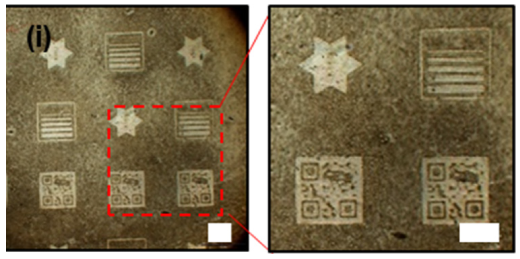
- Micro engraving: It is a printing technique which utilizes a heated die to transfer a detailed design onto a metallic foil placed between the die and the label substrate. This process not only enhances the label’s visual appeal but also offers a significant level of anti-counterfeiting protection. The intricate texture engraved is difficult to replicate, making it a valuable security feature. The resulting effect is visually similar to a hologram, albeit with a distinct appearance and tactile sensation [110] (Figure 12). Micro-engraved patterns can be either random or incorporate customized logos, further bolstering their ability to deter counterfeiting attempts [111] (Figure 13).
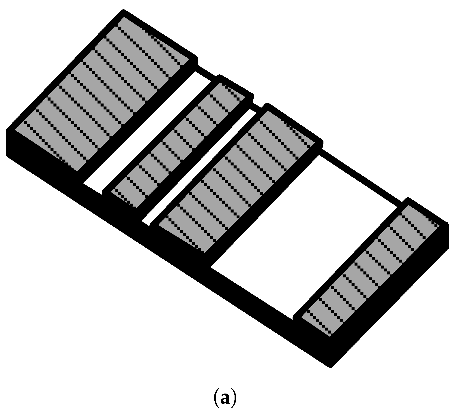
- Tags: While tags serve as a reliable method for product identification and verification of authenticity, particularly when coupled with more sophisticated technologies like holograms, RFID tags, OVI inks, or tracer fibers, their effectiveness is ultimately limited by the tensile strength of the attachment threads. They are typically affixed to the product using resilient threads, such as nylon strings or chains. In this context, the 3D electro-mechanical tag also needs some highlight. Such chipless tags have mechanical void inclusions within them, which changes the electromagnetic behaviour and are useful in anticounterfeiting applications, serving as a digital fingerprint. They are mostly printed by the additive manufacturing process involving rapid and hassle-free prototyping. The chipless tag takes the form of a solid dielectric cylinder, presenting a homogenous exterior. However, the information is embedded within the object’s internal structure. This is achieved by strategically placed voids that encode the data. This design offers a promising solution for anti-counterfeiting and security applications. It eliminates the vulnerability of information theft during the reading process or through visual inspection, a common weakness in other chipless systems. Furthermore, the data encoding method departs from the conventional on-off or amplitude schemes used in chipless RFID. Instead, it leverages a strategy that maximizes available states or non-overlapping uncertainty regions [112].
4. Chemical-Based Anticounterfeiting Techniques
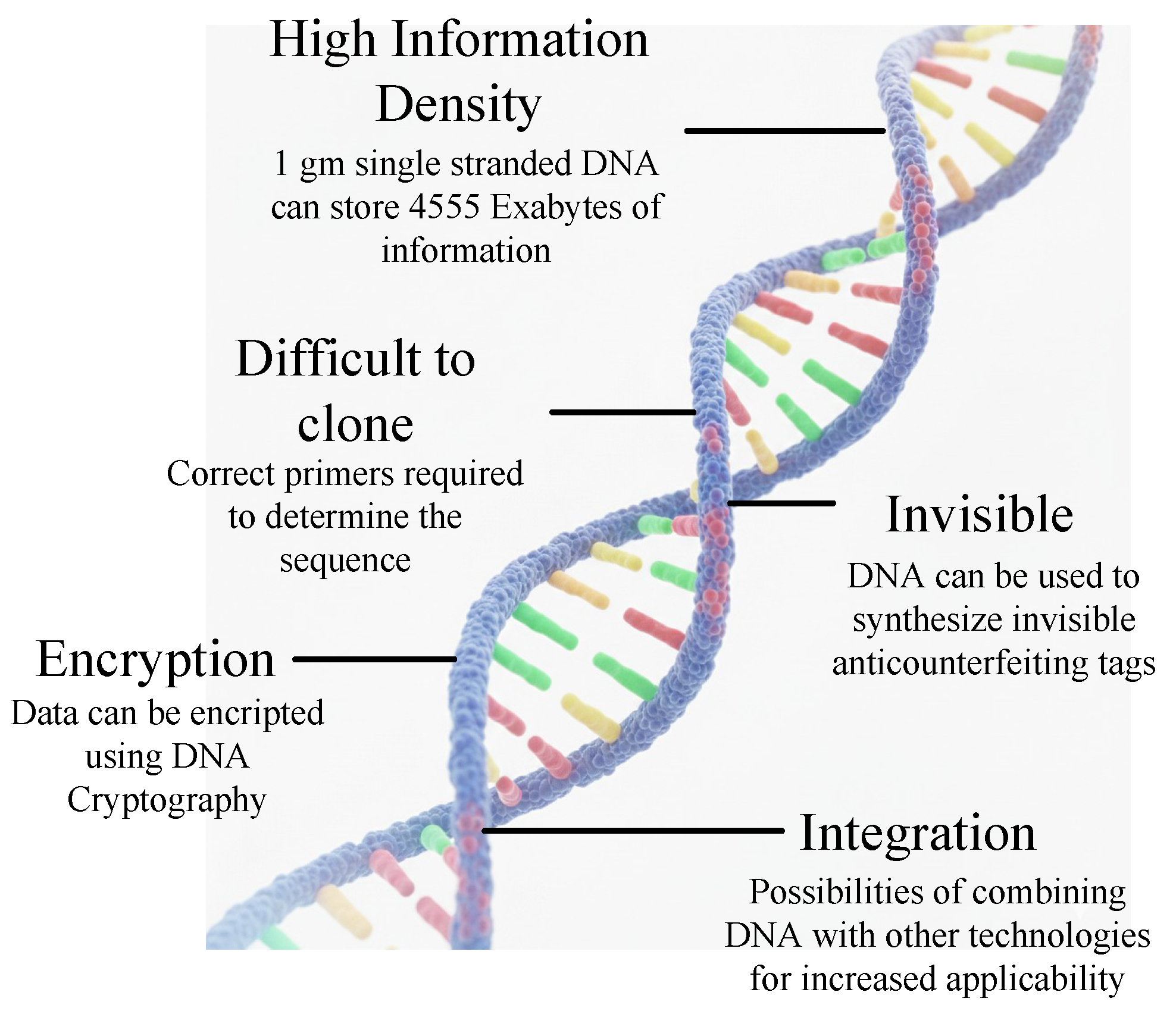
4.1. DNA Coding
- Association with products: Strategic Incorporation of DNA with important goods
- Conjugation with other technologies: Combining DNA with 1D/ 2D codes, RFID, etc.
- DNA stability and protection: Coating DNA with a protective layer
- Detection methodology: The detector should be fast, reliable and low cost
4.2. Chemical Encoding
4.3. Surface Analysis
4.4. Glue Coding
5. Marking Technologies for Anticounterfeiting
- The inherent properties of the technology: This encompasses the chemical and physical characteristics of the materials used, such as specialized inks with unique properties that are difficult to replicate accurately. Visual indications of tampering may also be a factor for technologies relying on overt markings.
- The encoded information within the marker: This can include complex data embedded within a graphic pattern or encrypted information within a code. The difficulty of cloning or reproducing this encoded information provides an additional layer of security.
- Versatility: Visual inspection allows for the application of these technologies to a wide range of products.
- Cost-effectiveness: The technology itself and verification procedures are often relatively inexpensive on a per-item basis.
- Ease of verification: In many cases, verification can be achieved through a simple visual inspection or by utilizing readily available technology such as smartphones.
5.1. Optical Memory Stripe
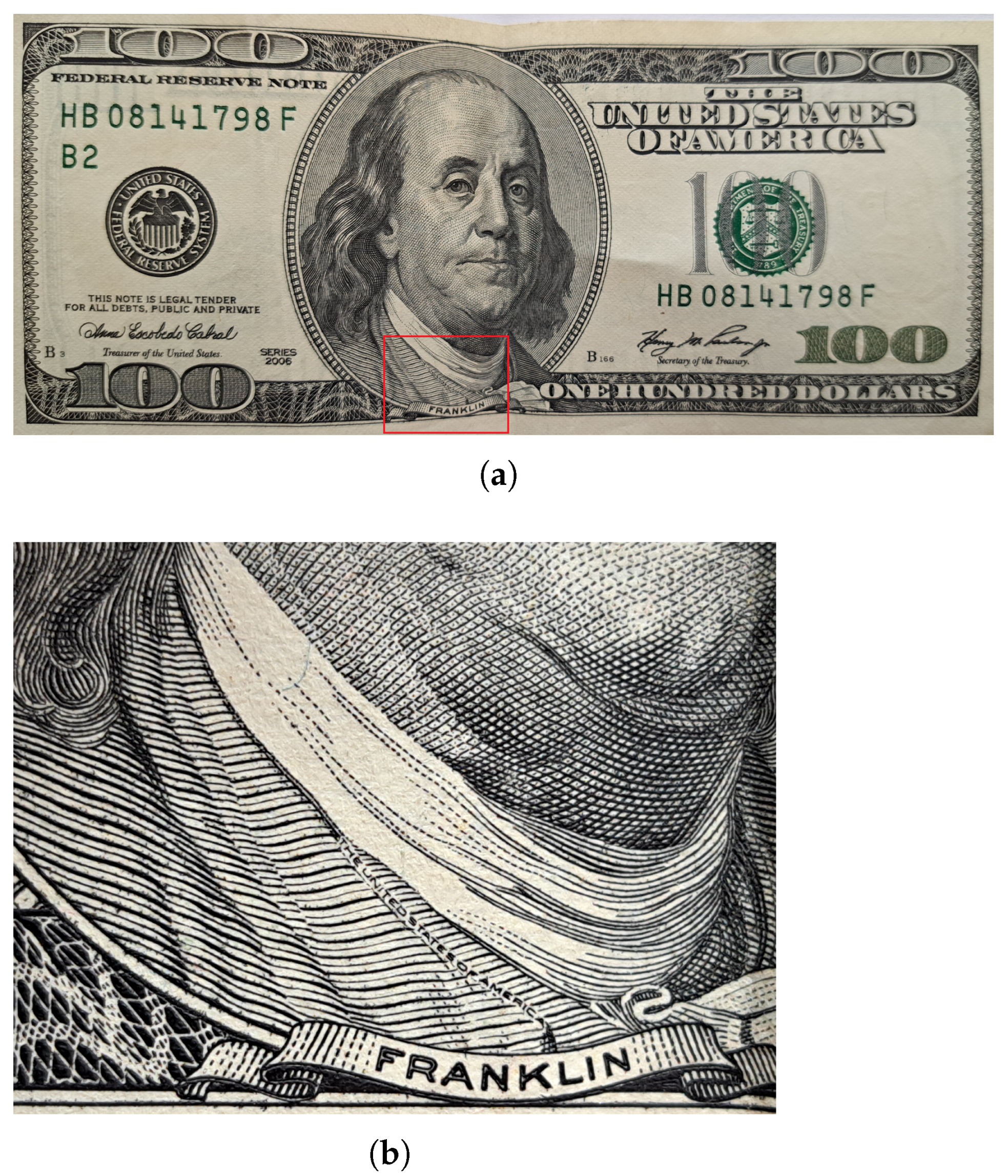
5.2. Microtext
5.3. Watermark
- Imperceptibility: The watermark should not introduce noticeable degradation to the host image.
- Invisibility: The watermark should be visually indistinguishable from the watermarked image.
- Robustness: The watermark must be resistant to various attacks, such as compression, cropping, geometric distortions, noise addition, filtering, and blurring. This robustness criterion is particularly important for robust watermarks, as opposed to fragile watermarks that are designed to be easily detectable upon tampering.
- Security: The watermark should be secure and challenging for unauthorized individuals to extract or access.
5.4. Copy Detection Patterns
- Reliance on Traditional Machine Learning: Existing approaches typically rely on traditional machine learning algorithms. These methods require manual feature extraction and selection by experts, often based on experience. This process necessitates the collection of vast datasets containing genuine and forged CDP images. Subsequently, features that best differentiate authentic from forged patterns are manually chosen. However, such traditional features are limited in their ability to represent complex information. Designing robust and highly discriminative manual features becomes increasingly challenging due to the rapid advancements in electronic equipment and increasingly sophisticated counterfeiting techniques. The inability to anticipate all potential forgery methods during design can lead to a decline in the effectiveness of traditional feature differentiation.
- Limited Mobile Integration: Most current identification methods require specialized equipment, hindering their accessibility for mobile device use. Dedicated and user-friendly anti-counterfeiting pattern authentication solutions for mobile platforms remain underdeveloped.
- Impact of Image Blur on Mobile Capture: Blur degradation frequently occurs in CDP images captured using mobile devices. This degradation stems from factors such as relative motion between the camera and the pattern, focusing errors, and other limitations inherent to mobile device photography. The resulting image quality reduction can negatively impact the accuracy of CDP authenticity identification. Consequently, the design of identification algorithms for mobile platforms needs to address the challenges posed by image blur and minimize its influence on authentication outcomes.
5.5. Guilloche Printing
5.6. Security Holograms
5.6.1. Diffractive Optically Variable Image Devices—DOVIDs
5.6.2. Interference Security Image Structures (ISISs)
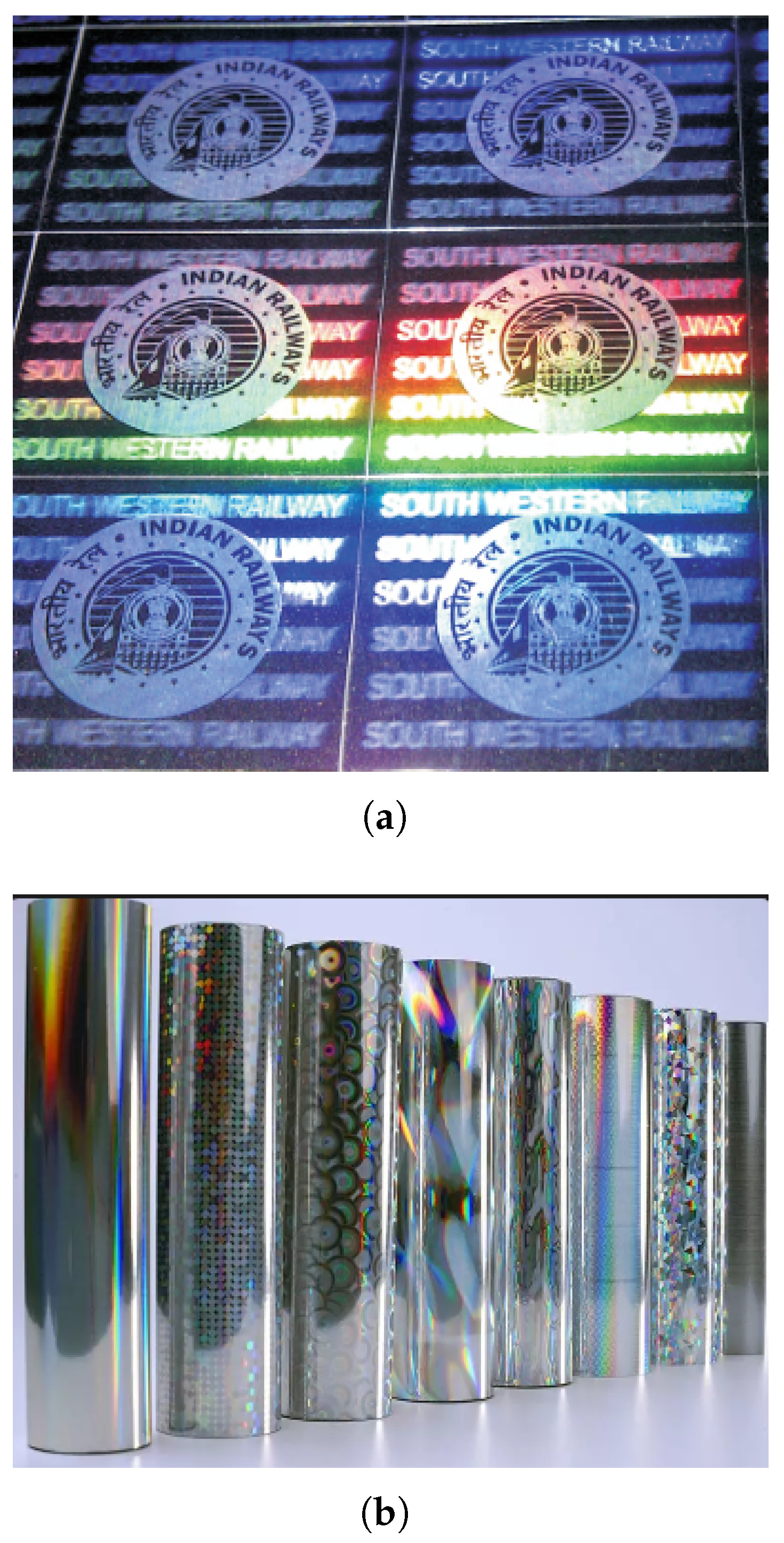
- 2D/3D holograms (multilayered): Two-dimensional and three-dimensional (2D/3D) holograms achieve a three-dimensional appearance by employing a series of visually layered two-dimensional diffractive elements. These elements contain holographic images carefully positioned behind one another to create a perceived depth, utilizing multiple layres. This technique offers substantial depth perception between the layers, often accompanied by a distinct shine on the topmost layer.Due to its established nature of over 20 years and proven effectiveness in generating high-quality security features, 2D/3D holography remains the dominant technology for most commercially available holographic stickers. These holograms exhibit a distinctive multilayered and multicolored appearance. One or two levels of two-dimensional graphics appear to ’float’ above or reside on the surface of the hologram. The background elements seemingly lie beneath or behind the hologram, creating a convincing illusion of depth (as shown in Figure 17a).
- 3D holograms: These holograms possess a three-dimensional quality, encompassing length, breadth, and depth. This illusion of depth arises from the utilization of a three-dimensional physical model that appears to project from the holographic plane. In essence, the holographic image captures the complete set of data pertaining to the wavefront emitted by an illuminated object.
- Dot-Matrix: In this technique, computer-controlled manipulation arranges microscopic dots into a well-defined relief structure. These precisely positioned dots act as a diffraction grating, selectively scattering light to reconstruct a holographic image. The computer generates a vast array of these dots, forming an intricate structure with diffractive properties. Dot-matrix holograms utilize multiple laser beams to create a pattern of minute, engraved dots. Each dot possesses a unique diffraction pattern, contributing to the hologram’s security features. The resulting visual effect is aesthetically pleasing, often exhibiting dynamic kinetic effects and displaying variable images with a high-quality finish.
- Hot Stamping Foil (HSF): In this method, pre-dried inks or foils are adhered to a target surface using high temperatures. Dry lithography finds extensive application in securing paper and plastic products, although its versatility allows for its use with various other materials (Figure 17b).
- De-metallized holograms: In this process, a layer of aluminium is deposited onto the hologram. Subsequently, specific regions are selectively removed to create a desired graphic pattern. This technique enables the creation of printouts containing both metallized and transparent areas on a single film, offering enhanced security features or improved design aesthetics [170].
5.7. Machine Readable Codes
5.7.1. One-Dimensional Code
5.7.2. Two-Dimensional Code
5.8. Inks
5.8.1. UV Sensitive
5.8.2. IR Sensitive
5.8.3. Magnetic
5.8.4. Thermochromic
5.8.5. Reactive
- Erasable: Erasable inks are often employed in a background capacity for specific documents. Their functionality becomes apparent when an attempt is made to erase information, as the ink readily succumbs to friction and disappears [186]. This characteristic makes them particularly valuable for safeguarding documents like checks and certificates against unauthorized alterations. Notably, erasable inks are best suited for dry and wet offset printing methods and are incompatible with laser printing technology.
- Solvent-sensitive: Designed to thwart forgery attempts, solvent-sensitive inks exhibit a marked reaction upon exposure to specific solvents or chemicals commonly used for tampering, such as bleach, alcohol, or acetone. This reaction manifests as a visible transformation of the ink, including running, color change, or stain development, thereby exposing any attempt to alter the document.
- Fugitive: Fugitive inks offer a security measure by readily revealing tampering attempts. These inks are formulated to react with water-based solutions (aqueous solutions) or other inks, causing visible smudging within the printed area [187]. This characteristic makes them particularly useful for safeguarding documents like checks, where any effort to alter the content with ink or a liquid solution would be readily apparent due to the resulting smudges.
5.8.6. Penetrating
- Biometric Taggants: These inks incorporate covert security elements in the form of DNA taggants [119]. These microscopic markers react to designated solvents or require specialized equipment for detection. This technology facilitates the authentication of a wide range of products and documents. In essence, DNA taggants function as a hidden layer of security that necessitates technical expertise to verify the genuineness of an item.
- Bleeding Ink: This security ink offers a convenient method for document authentication. While appearing black upon printing, it undergoes a chromatic shift to red when exposed to a water-based solution (aqueous solution). This transformation allows for straightforward verification without the need for specialized reagents. The application process is simple, requiring only a moistened fingertip to be drawn across the printed area, initiating the color change to red. It is important to note that this ink is specifically suited for dry offset printing.
- Metameric Ink: These inks leverage the principle of metamerism, where the combination of two colors creates a resultant appearance that varies under different lighting conditions. This phenomenon allows for the covert integration of security features, such as numbers only visible when viewed under a particular coloured filter [190].
6. Discussion
- Tamper-evident Packaging: Packaging with self-destructing seals or unique identification codes discourages tampering and provides additional layers of verification.
- Supply Chain Management: Robust tracking systems from manufacturing to distribution can identify and eliminate potential vulnerabilities within the supply chain.
- Digital Authentication: Implementing product serialization and track-and-trace systems provide a digital layer of verification. Products with unique identifiers can be authenticated through online databases, further strengthening the anti-counterfeiting strategy.
- Our current scenario
- -
- The market for anti-counterfeiting/secure packaging solutions is large and growing fast as brands and regulators respond to growing counterfeit volumes [191].
- -
- Solutions today are a mix of physical features (holograms, optically variable inks, taggants), authentication layers (NFC/QR with backend verification), and forensic/lab methods (molecular taggants, DNA, isotopic markers)
- High-impact trends
- -
- Molecular/DNA taggants moving from niche to viable commercial use—New hybrid DNA and polynucleotide tag systems allow microscopic, hard-to-copy markers that can be read with paper/kit-based or lab readers; these are now appearing in high-security trials and patents. This makes authenticity tied to chemistry rather than optics alone [192].
- -
- Scalability of Smart packaging (NFC + consumer verification)—NFC and tamper-aware chips are increasingly embedded in pharma, luxury, and packaging so consumers (or customs officers) can verify origin or a tamper flag with a smartphone. Expect rapid adoption where consumer trust and safety are critical [193].
- -
- Blockchain and product-level digital ledgers for provenance—Blockchain (plus IoT anchors) is maturing as a tool for immutable provenance records along supply chains; it is shifting from pilot projects to production deployments for high-value goods and regulated products [194].
- -
- AI, computer vision and signal analysis for detection—Deep-learning models detect subtle optical, spectral or electrical signatures (e.g., for semiconductor chips or packaging) that humans miss; universities and standards labs have recently published promising prototypes. Expect AI to be used both for automated inspection and for flagging suspicious supply-chain behavior [195].
- -
- Market growth and industry consolidation—Industry reports show strong CAGR in secure packaging and anti-counterfeit markets as companies buy, integrate, and scale these technologies. Investment into combined physical + digital stacks is increasing [191].
Author Contributions
Funding
Institutional Review Board Statement
Informed Consent Statement
Data Availability Statement
Conflicts of Interest
References
- The Economic Impacts of Counterfeiting and Piracy—Report prepared for BASCAP and INTA. Front. Econ. 2017.
- Available online: https://www.asianage.com/business/counterfeiters-use-e-com-target-larger-audiences-613/ (accessed on 3 April 2024).
- Angrist, J.D.; Pischke, J.S. Mostly Harmless Econometrics: An Empiricist’s Companion; Princeton University Press: Princeton, NJ, USA, 2009. [Google Scholar]
- Available online: https://www.trustconcept.com/en/newsroom/news/whitepapers/white-paper-how-counterfeit-proof-is-your-product/ (accessed on 3 April 2024).
- Sola, A.; Sai, Y.; Trinchi, A.; Chu, C.; Shen, S.; Chen, S. How can we provide additively manufactured parts with a fingerprint? A review of tagging strategies in additive manufacturing. Materials 2021, 15, 85. [Google Scholar] [CrossRef] [PubMed]
- Butt, I.; Al Balushi, M.K.; Lee, S.H.; Mohan, M.; Ahmad Khan, N.; Haines, S. Four decades of counterfeit research: A bibliometric analysis. Cogent Bus. Manag. 2023, 10, 2284814. [Google Scholar]
- Subramaniam, R.; Azzuhri, S.R.; Wah, T.Y.; Mahmood, A.; Balakrishnan, V. A Holistic Anti-Counterfeiting Platform Using NFC and Blockchain Technologies. Comput. Mater. Contin. 2025, 83, 4257–4280. [Google Scholar]
- Smith, C.L.; Brooks, D.J. Chapter 7—Integrated Identification Technology. In Security Science; Smith, C.L., Brooks, D.J., Eds.; Butterworth-Heinemann: Boston, MA, USA, 2013; pp. 153–175. [Google Scholar] [CrossRef]
- Hummel, R.E. Applications in Electronic Properties of Materials. In Electronic Properties of Materials; Springer: New York, NY, USA, 2011; pp. 385–401. [Google Scholar] [CrossRef]
- Inoue, A.; Kong, F. Soft Magnetic Materials. In Encyclopedia of Smart Materials; Olabi, A.G., Ed.; Elsevier: Oxford, UK, 2022; pp. 10–23. [Google Scholar] [CrossRef]
- Husemann, D. The smart card: Don’t leave home without it. IEEE Concurr. 1999, 7, 24–27. [Google Scholar] [CrossRef]
- Yadav, S.; Verma, S. A Comprehensive Study of Security Features for Modern Payment Services Cards and Identity Cards. Int. J. Adv. Res. Multidiscip. Trends (IJARMT) 2025, 2, 675–683. [Google Scholar]
- Shelfer, K.M.; Procaccino, J.D. Smart card evolution. Commun. ACM 2002, 45, 83–88. [Google Scholar] [CrossRef]
- Rankl, W.; Effing, W. Smart Card Handbook; John Wiley & Sons: Hoboken, NJ, USA, 2004. [Google Scholar]
- Chin, L.P.; Wu, C.L. The role of electronic container seal (E-seal) with RFID technology in the container security initiatives. In Proceedings of the 2004 International Conference on MEMS, NANO and Smart Systems (ICMENS’04), Banff, AB, Canada, 25–27 August 2004; pp. 116–120. [Google Scholar]
- Kadir, E.A.; Rosa, S.L.; Gunawan, H. Application of RFID technology and e-seal in container terminal process. In Proceedings of the 2016 4th International Conference on Information and Communication Technology (ICoICT), Bandung, Indonesia, 25–27 May 2016; pp. 1–6. [Google Scholar]
- Yeun, C.Y.; Shemaili, M.A.B.; Zemerly, M.J.; Mubarak, K.; Yeun, H.K.; Chang, Y.S.; Zafar, B.; Simsim, M.; Salih, Y. ID-based secure real-time tracking system. Int. J. Adv. Logist. 2015, 4, 100–114. [Google Scholar] [CrossRef]
- Lampe, M.; Strassner, M.; Fleisch, E. RFID in movable asset management. In Ubiquitous and Pervasive Commerce: New Frontiers for Electronic Business; Springer: Berlin/Heidelberg, Germany, 2005; pp. 53–71. [Google Scholar]
- Min, J.U.; Park, M. Electronic cargo seal for safe and secure supply chain traceability. J. Int. Logist. Trade 2007, 5, 47–56. [Google Scholar] [CrossRef]
- Available online: https://www.entrust.com/sites/default/files/documentation/whitepapers/rss-electronic-and-digital-signatures-wp.pdf/ (accessed on 4 April 2024).
- Available online: https://web.customs.gov.tw/en/singlehtml/3428?cntId=242f4a635e4646749f0c46f2cf248901 (accessed on 8 May 2024).
- Shah, R.Y.; Prajapati, P.N.; Agrawal, Y. Anticounterfeit packaging technologies. J. Adv. Pharm. Technol. Res. 2010, 1, 368–373. [Google Scholar] [CrossRef]
- Bansal, D.; Malla, S.; Gudala, K.; Tiwari, P. Anti-counterfeit technologies: A pharmaceutical industry perspective. Sci. Pharm. 2013, 81, 1–14. [Google Scholar] [CrossRef] [PubMed]
- Soon, J.M.; Manning, L. Developing anti-counterfeiting measures: The role of smart packaging. Food Res. Int. 2019, 123, 135–143. [Google Scholar] [CrossRef] [PubMed]
- Xianyu, B.; Jianzhong, Z.; Qian, F.; Yun, G. Efficient electronic seal system. Appl. Mech. Mater. 2014, 610, 221–224. [Google Scholar]
- Maritano, V.; Barge, P.; Biglia, A.; Comba, L.; Aimonino, D.R.; Tortia, C.; Gay, P. Anticounterfeiting and Fraud Mitigation Solutions for High-value Food Products. J. Food Prot. 2024, 87, 100251. [Google Scholar] [CrossRef]
- Available online: https://www.agid.gov.it/en/platforms/procurement (accessed on 10 June 2024).
- Available online: https://www.thailand.go.th/issue-focus-detail/006_098 (accessed on 10 June 2024).
- Juels, A.; Weis, S.A. Authenticating pervasive devices with human protocols. In Proceedings of the Advances in Cryptology–CRYPTO 2005: 25th Annual International Cryptology Conference, Santa Barbara, CA, USA, 14–18 August 2005; Proceedings 25. Springer: Berlin/Heidelberg, Germany, 2005; pp. 293–308. [Google Scholar]
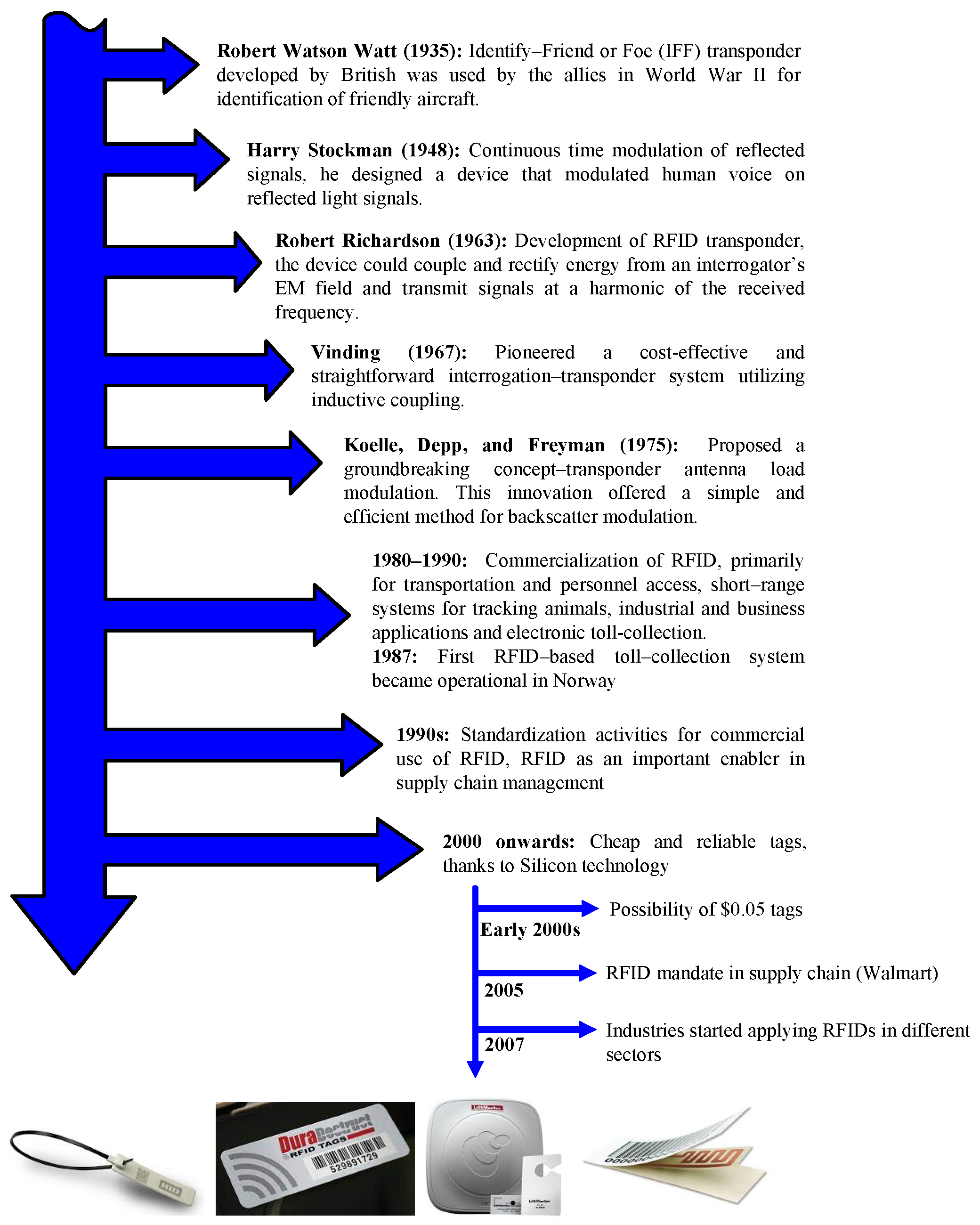
- Hunt, V.D.; Puglia, A.; Puglia, M. History and evolution of RFID technology. In Pošta, Telekomunikácie a Elektronický Obchod; Wiley Telecom: Hoboken, NJ, USA, 2007; pp. 17–22. [Google Scholar]
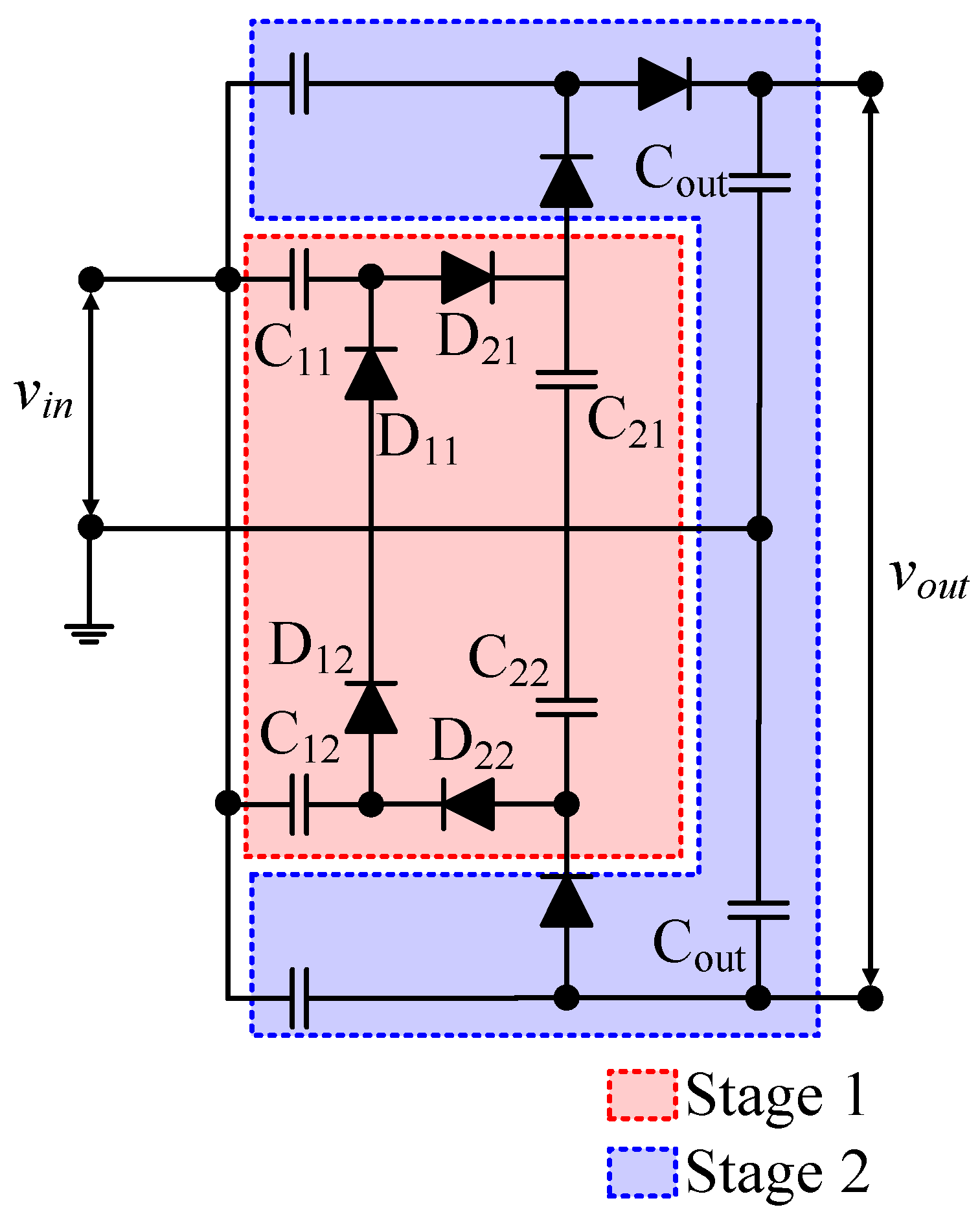
- Curty, J.P.; Joehl, N.; Krummenacher, F.; Dehollain, C.; Declercq, M. A model for μ-power rectifier analysis and design. IEEE Trans. Circuits Syst. I Regul. Pap. 2005, 52, 2771–2779. [Google Scholar] [CrossRef]
- Available online: https://sweet.ua.pt/andre.zuquete/Aulas/IRFID/11-12/docs/IRFID_nbc_3.pdf (accessed on 11 June 2024).
- Sidén, J.; Nilsson, H.E. RFID Antennas–Possibilities and Limitations. Radio Freq. Identif. Fundam. Appl. Des. Methods Solut. 2010, 5, 324. [Google Scholar]
- Nikitin, P.V.; Rao, K.S. Theory and measurement of backscattering from RFID tags. IEEE Antennas Propag. Mag. 2006, 48, 212–218. [Google Scholar] [CrossRef]
- Available online: https://www.atlasrfidstore.com/rfid-insider/active-rfid-vs-passive-rfid/ (accessed on 3 June 2024).
- Sahin, S.; Ozcan, H.; Kucuk, K. Smarttag: An indoor positioning system based on smart transmit power scheme using active tags. IEEE Access 2018, 6, 23500–23510. [Google Scholar] [CrossRef]
- Molapo, N.A.; Malekian, R.; Nair, L. Real-time livestock tracking system with integration of sensors and beacon navigation. Wirel. Pers. Commun. 2019, 104, 853–879. [Google Scholar] [CrossRef]
- Periša, M.; Cvitić, I.; Peraković, D.; Husnjak, S. Beacon technology for real-time informing the traffic network users about the environment. Transport 2019, 34, 373–382. [Google Scholar] [CrossRef]
- Available online: https://www.ti.com/sc/docs/products/micro/msp430/39113.pdf (accessed on 2 May 2024).
- Solar, H.; Beriain, A.; Berenguer, R.; Sosa, J.; Montiel-Nelson, J.A. Semi-Passive UHF RFID Sensor Tags: A Comprehensive Review. IEEE Access 2023, 11, 135583–135599. [Google Scholar] [CrossRef]
- Available online: https://www.digikey.com/ (accessed on 3 May 2024).
- Ali, Z.; Perret, E.; Barbot, N.; Siragusa, R. Chipless RFID Authentication: Design, Realization and Characterization; John Wiley & Sons: Hoboken, NJ, USA, 2022. [Google Scholar]
- Brinker, K.R.; Zoughi, R. A review of chipless RFID measurement methods, response detection approaches, and decoding techniques. IEEE Open J. Instrum. Meas. 2022, 1, 1–31. [Google Scholar] [CrossRef]
- Lopez-Iturri, P.; Ruiz-Feliú, R.; Guembe, I.P.; Klaina, H.; Francés, F.J.T.; Martinez, P.; Amado, I.N.; Basarte, E.; Morentin, J.; Saenz, A.G.; et al. Implementation of a low-cost chipless RFID system with paper-based substrates printed tags for traceability applications in the packaging sector. IEEE Sens. J. 2023, 23, 14923–14937. [Google Scholar] [CrossRef]
- Karmakar, N.C.; Amin, E.M.; Saha, J.K. Literature Review. In Chipless RFID Sensors; John Wiley & Sons: Hoboken, NJ, USA, 2016; pp. 13–28. [Google Scholar] [CrossRef]
- Khadka, G.; Feng, J.; Karmakar, N.C. Chipless rfid: A low-cost consumer electronics in the retail marketplace for moving item detection. In Proceedings of the 2019 IEEE 8th Global Conference on Consumer Electronics (GCCE), Osaka, Japan, 15–18 October 2019; pp. 618–621. [Google Scholar]
- Subrahmannian, A.; Behera, S.K. Chipless RFID sensors for IoT-based healthcare applications: A review of state of the art. IEEE Trans. Instrum. Meas. 2022, 71, 1–20. [Google Scholar] [CrossRef]
- Herrojo, C.; Mata-Contreras, J.; Nunez, A.; Paredes, F.; Ramon, E.; Martin, F. Near-field chipless-RFID system with high data capacity for security and authentication applications. IEEE Trans. Microw. Theory Tech. 2017, 65, 5298–5308. [Google Scholar] [CrossRef]
- Pappu, R.; Recht, B.; Taylor, J.; Gershenfeld, N. Physical one-way functions. Science 2002, 297, 2026–2030. [Google Scholar] [CrossRef] [PubMed]
- Scholz, A.; Zimmermann, L.; Gengenbach, U.; Koker, L.; Chen, Z.; Hahn, H.; Sikora, A.; Tahoori, M.B.; Aghassi-Hagmann, J. Hybrid low-voltage physical unclonable function based on inkjet-printed metal-oxide transistors. Nat. Commun. 2020, 11, 5543. [Google Scholar] [CrossRef] [PubMed]
- Gao, B.; Lin, B.; Pang, Y.; Xu, F.; Lu, Y.; Chiu, Y.C.; Liu, Z.; Tang, J.; Chang, M.F.; Qian, H.; et al. Concealable physically unclonable function chip with a memristor array. Sci. Adv. 2022, 8, eabn7753. [Google Scholar] [CrossRef] [PubMed]
- Yang, M.; Ye, Z.; Pan, H.; Farhat, M.; Cetin, A.E.; Chen, P.Y. Electromagnetically unclonable functions generated by non-Hermitian absorber-emitter. Sci. Adv. 2023, 9, eadg7481. [Google Scholar] [CrossRef]
- Gao, Y.; Al-Sarawi, S.F.; Abbott, D. Physical unclonable functions. Nat. Electron. 2020, 3, 81–91. [Google Scholar] [CrossRef]
- Tarik, F.B.; Famili, A.; Lao, Y.; Ryckman, J.D. Scalable and CMOS compatible silicon photonic physical unclonable functions for supply chain assurance. Sci. Rep. 2022, 12, 15653. [Google Scholar] [CrossRef] [PubMed]
- Tsai, W.K.; Lai, Y.S.; Tseng, P.J.; Liao, C.H.; Chan, Y.H. Dual colorimetric and fluorescent authentication based on semiconducting polymer dots for anticounterfeiting applications. ACS Appl. Mater. Interfaces 2017, 9, 30918–30924. [Google Scholar] [CrossRef]
- Alidaei-Sharif, H.; Roghani-Mamaqani, H.; Babazadeh-Mamaqani, M.; Sahandi-Zangabad, K.; Abdollahi, A.; Salami-Kalajahi, M. Photochromic polymer nanoparticles as highly efficient anticounterfeiting nanoinks for development of photo-switchable encoded tags. J. Photochem. Photobiol. A Chem. 2023, 436, 114343. [Google Scholar] [CrossRef]
- Dong, Y.; Ling, Y.; Wang, D.; Liu, Y.; Chen, X.; Zheng, S.; Wu, X.; Shen, J.; Feng, S.; Zhang, J.; et al. Harnessing molecular isomerization in polymer gels for sequential logic encryption and anticounterfeiting. Sci. Adv. 2022, 8, eadd1980. [Google Scholar] [CrossRef]
- Liu, Y.; Han, F.; Li, F.; Zhao, Y.; Chen, M.; Xu, Z.; Zheng, X.; Hu, H.; Yao, J.; Guo, T.; et al. Inkjet-printed unclonable quantum dot fluorescent anti-counterfeiting labels with artificial intelligence authentication. Nat. Commun. 2019, 10, 2409. [Google Scholar] [CrossRef] [PubMed]
- Yakunin, S.; Chaaban, J.; Benin, B.M.; Cherniukh, I.; Bernasconi, C.; Landuyt, A.; Shynkarenko, Y.; Bolat, S.; Hofer, C.; Romanyuk, Y.E.; et al. Radiative lifetime-encoded unicolour security tags using perovskite nanocrystals. Nat. Commun. 2021, 12, 981. [Google Scholar] [CrossRef]
- Gao, Z.; Han, Y.; Wang, F. Cooperative supramolecular polymers with anthracene–endoperoxide photo-switching for fluorescent anti-counterfeiting. Nat. Commun. 2018, 9, 3977. [Google Scholar] [CrossRef]
- Zhang, J.; Liu, Y.; Njel, C.; Ronneberger, S.; Tarakina, N.V.; Loeffler, F.F. An all-in-one nanoprinting approach for the synthesis of a nanofilm library for unclonable anti-counterfeiting applications. Nat. Nanotechnol. 2023, 18, 1027–1035. [Google Scholar] [CrossRef]
- Wang, K.; Shi, J.; Lai, W.; He, Q.; Xu, J.; Ni, Z.; Liu, X.; Pi, X.; Yang, D. All-silicon multidimensionally-encoded optical physical unclonable functions for integrated circuit anti-counterfeiting. Nat. Commun. 2024, 15, 3203. [Google Scholar] [CrossRef]
- Rong, Y.; Wu, C.; Yu, J.; Zhang, X.; Ye, F.; Zeigler, M.; Gallina, M.E.; Wu, I.C.; Zhang, Y.; Chan, Y.H.; et al. Multicolor fluorescent semiconducting polymer dots with narrow emissions and high brightness. ACS Nano 2013, 7, 376–384. [Google Scholar] [CrossRef]
- Creamer, A.; Fiego, A.L.; Agliano, A.; Prados-Martin, L.; Høgset, H.; Najer, A.; Richards, D.A.; Wojciechowski, J.P.; Foote, J.E.; Kim, N.; et al. Modular synthesis of semiconducting graft copolymers to achieve “clickable” fluorescent nanoparticles with long circulation and specific cancer targeting. Adv. Mater. 2024, 36, 2300413. [Google Scholar] [CrossRef]
- Wu, C.; Schneider, T.; Zeigler, M.; Yu, J.; Schiro, P.G.; Burnham, D.R.; McNeill, J.D.; Chiu, D.T. Bioconjugation of ultrabright semiconducting polymer dots for specific cellular targeting. J. Am. Chem. Soc. 2010, 132, 15410–15417. [Google Scholar] [CrossRef]
- Ferraro, A.; Lio, G.E.; Bruno, M.D.L.; Nocentini, S.; De Santo, M.P.; Wiersma, D.S.; Riboli, F.; Caputo, R.; Barberi, R.C. Hybrid camouflaged anticounterfeiting token in a paper substrate. Adv. Mater. Technol. 2023, 8, 2201010. [Google Scholar] [CrossRef]
- Tehranipoor, M.; Pundir, N.; Vashistha, N.; Farahmandi, F. Hybrid Extrinsic Radio Frequency PUF. In Hardware Security Primitives; Springer: Berlin/Heidelberg, Germany, 2022; pp. 81–95. [Google Scholar]
- Chang, K.; Liu, Z.; Chen, H.; Sheng, L.; Zhang, S.; Chiu, D.T.; Yin, S.; Wu, C.; Qin, W. Conjugated polymer dots for ultra-stable full-color fluorescence patterning. Small 2014, 10, 4270–4275. [Google Scholar] [CrossRef] [PubMed]
- Yao, Z.; Wang, X.; Liu, J.; Zhou, S.; Zhang, Z.; He, S.; Liu, J.; Wu, C.; Fang, X. Photoswitchable semiconducting polymer dots for pattern encoding and superresolution imaging. Chem. Commun. 2023, 59, 2469–2472. [Google Scholar] [CrossRef] [PubMed]
- Zuo, M.; Qian, W.; Li, T.; Hu, X.Y.; Jiang, J.; Wang, L. Full-color tunable fluorescent and chemiluminescent supramolecular nanoparticles for anti-counterfeiting inks. ACS Appl. Mater. Interfaces 2018, 10, 39214–39221. [Google Scholar] [CrossRef] [PubMed]
- Yang, C.; Liu, B.; Wang, Y.; Chen, Y.; Li, H.; Zhang, X.; Sun, G. The applications of NVM technology in hardware security. In Proceedings of the 26th edition on Great Lakes Symposium on VLSI, New York, NY, USA, 30 April 2016; pp. 311–316. [Google Scholar]
- Wan, M.; He, Z.; Han, S.; Dai, K.; Zou, X. An invasive-attack-resistant PUF based on switched-capacitor circuit. IEEE Trans. Circuits Syst. I Regul. Pap. 2015, 62, 2024–2034. [Google Scholar] [CrossRef]
- Arcenegui, J.; Arjona, R.; Román, R.; Baturone, I. Secure combination of IoT and blockchain by physically binding IoT devices to smart non-fungible tokens using PUFs. Sensors 2021, 21, 3119. [Google Scholar] [CrossRef]
- Robson, N.; Safran, J.; Kothandaraman, C.; Cestero, A.; Chen, X.; Rajeevakumar, R.; Leslie, A.; Moy, D.; Kirihata, T.; Iyer, S. Electrically programmable fuse (efuse): From memory redundancy to autonomic chips. In Proceedings of the 2007 IEEE Custom Integrated Circuits Conference, San Jose, CA, USA, 16–19 September 2007; pp. 799–804. [Google Scholar]
- Wong, C.W.; Wu, M. A study on PUF characteristics for counterfeit detection. In Proceedings of the 2015 IEEE International Conference on Image Processing (ICIP), Quebec City, QC, Canada, 27–30 September 2015; pp. 1643–1647. [Google Scholar]
- Mamat, K.S.; Aung, P.P.; Ooi, C.Y. Systematic Review of Physically Unclonable Functions on SRAMs for Secured Authentication. J. Electr. Electron. Res. (JEER) 2024, 1, 17–26. [Google Scholar] [CrossRef]
- Lin, K.H.; Wang, W.H.; Wang, I.C. The Implementation of the Physical Unclonable Function in a Field-Programmable Gate Array for Enhancing Hardware Security. Eng. Proc. 2025, 92, 23. [Google Scholar]
- Alkanhal, M.; Alali, A.; Younis, M. A distributed lightweight PUF-based mutual authentication protocol for IoV. IoT 2023, 5, 1–19. [Google Scholar] [CrossRef]
- Qureshi, M.A.; Munir, A. PUF-RAKE: A PUF-based robust and lightweight authentication and key establishment protocol. IEEE Trans. Dependable Secur. Comput. 2021, 19, 2457–2475. [Google Scholar] [CrossRef]
- Bian, J.; Huang, Z.; Lin, Y.; Yang, Z.; Liang, H.; Ni, T. Reliability analysis and comparison of ring-PUF based on probabilistic models. Microelectron. J. 2024, 144, 106072. [Google Scholar] [CrossRef]
- Saadvikaa, N.; Saketi, K.J.; Gopishetti, A.; Degala, B.; Anumandla, K.K. PUF modeling attacks using deep learning and machine learning algorithms. Eng. Proc. 2023, 56, 187. [Google Scholar]
- AL, A.M.; Mohan, N. Design and Evaluation of Hybrid Physically Unclonable Functions for Enhanced Security. In Proceedings of the 2025 IEEE 5th International Conference on VLSI Systems, Architecture, Technology and Applications (VLSI SATA), Bangalore, India, 23–24 May 2025; pp. 1–6. [Google Scholar]
- Cheung, H.; Choi, S.H. Implementation issues in RFID-based anti-counterfeiting systems. Comput. Ind. 2011, 62, 708–718. [Google Scholar] [CrossRef]
- Xu, L.; Yang, K. Security Film and Process for Preparation Thereof. U.S. Patent 8,541,095, 24 September 2013. [Google Scholar]
- Feldmann, J.; Spiehl, D.; Dörsam, E. Paper embossing tools: A fast fabrication workflow using image processing and stereolithography additive manufacturing. In Proceedings of the Advances in Printing and Media Technology: Proceedings of the 47th International Research Conference of Iarigai, Athens, Greece, 19–23 September 2021; pp. 19–23. [Google Scholar]
- Muke, S.; Fox, P.; Jackson, W.; Victoria, C. Improvements in Document Security—The Next Generation. In Proceedings of the International Congress of Imaging Science, Portland, Oregon, 16–20 October 2006; pp. 424–427. [Google Scholar]
- Kuznetsov, Y.V. Principles of Image Printing Technology; Springer: Berlin/Heidelberg, Germany, 2021. [Google Scholar]
- He, W.F.; Tan, Z.H.; Chan, D.L.; Lu, Y.Z.; Qiu, J.C. Research to Factors of Screen Overprinting in Color Film Printing. Appl. Mech. Mater. 2012, 200, 739–742. [Google Scholar] [CrossRef]
- Roy, S.; Rhim, J.W. Starch/agar-based functional films integrated with enoki mushroom-mediated silver nanoparticles for active packaging applications. Food Biosci. 2022, 49, 101867. [Google Scholar] [CrossRef]
- Ghizdareanu, A.I.; Banu, A.; Pasarin, D.; Ionita, A.; Nicolae, C.A.; Gabor, A.R.; Pătroi, D. Enhancing the Mechanical Properties of Corn Starch Films for Sustainable Food Packaging by Optimizing Enzymatic Hydrolysis. Polymers 2023, 15, 1899. [Google Scholar] [CrossRef]
- Żołek-Tryznowska, Z.; Piłczyńska, K.; Murawski, T.; Jeznach, A.; Niczyporuk, K. Study on the Printability of Starch-Based Films Using Ink-Jet Printing. Materials 2024, 17, 455. [Google Scholar] [CrossRef]
- Li, Z.; Chen, Z.; Qian, J.; Ke, X.; Liu, X. Superior fluorescent ‘Color Paper-based Displayer’for advanced anti-counterfeiting and multi-layer information encryption. Chem. Eng. J. 2025, 507, 160047. [Google Scholar] [CrossRef]
- Lee, R. Micro-technology for anti-counterfeiting. Microelectron. Eng. 2000, 53, 513–516. [Google Scholar] [CrossRef]
- Fujikawa, M.; Takayama, K.; Fuchi, S. Anti-counterfeiting Technique for Molded Resin Articles. In Proceedings of the 3rd International Conference on Industrial and Business Engineering, Sapporo, Japan, 17–19 August 2017; pp. 46–50. [Google Scholar]
- Meng, Y.; Liu, F.; Umair, M.M.; Ju, B.; Zhang, S.; Tang, B. Patterned and iridescent plastics with 3D inverse opal structure for anticounterfeiting of the banknotes. Adv. Opt. Mater. 2018, 6, 1701351. [Google Scholar] [CrossRef]
- Dietemann, P. Security Sheet Including an Iridescent Security Mark. U.S. Patent 10,259,247, 16 April 2019. [Google Scholar]
- Fan, Y.; Jin, X.; Wang, M.; Gu, Y.; Zhou, J.; Zhang, J.; Wang, Z. Multimode dynamic photoluminescent anticounterfeiting and encryption based on a dynamic photoluminescent material. Chem. Eng. J. 2020, 393, 124799. [Google Scholar] [CrossRef]
- Li, M.; Feng, Y.; Tian, Q.; Yao, W.; Liu, L.; Li, X.; Wang, H.; Wu, W. Tunable and ultra-stable UV light-switchable fluorescent composites for information hiding and storage. Dalton Trans. 2018, 47, 11264–11271. [Google Scholar] [CrossRef] [PubMed]
- Sripradit, A.; Theeradejvanichkul, T. A self-color-changing film with periodic nanostructure for anti-counterfeit application. Appl. Sci. 2022, 12, 6776. [Google Scholar] [CrossRef]
- Zhu, C.; Tao, L.Q.; Peng, Z.; Wang, G.; Huang, Y.; Zou, S.; Sun, H.; Zhao, Y.; Chen, X.; Ren, T.L. An integrated luminescent information encryption–decryption and anticounterfeiting chip based on laser induced graphene. Adv. Funct. Mater. 2021, 31, 2103255. [Google Scholar] [CrossRef]
- Lazaro, A.; Cujilema, M.R.; Villarino, R.; Lazaro, M.; Girbau, D. A novel approach for wine anti-counterfeiting using laser-induced graphene chipless RFID tags on cork. Sci. Rep. 2025, 15, 12750. [Google Scholar] [CrossRef]
- Ha, B.H.; Ahn, S.; Bae, H.S.; Kang, H.S.; Kim, J.o.; Noh, J. Fast and direct engraving of iridescent lettering on original product surface using laser interference to prevent counterfeiting. Opt. Lasers Eng. 2018, 107, 214–220. [Google Scholar] [CrossRef]
- Hoveida, P.; Phoulady, A.; Choi, H.; May, N.; Shahbazmohamadi, S.; Tavousi, P. Terahertz-readable laser engraved marks as a novel solution for product traceability. Sci. Rep. 2023, 13, 12474. [Google Scholar] [CrossRef]
- Tomescu, R.; Parvulescu, C.; Cristea, D.; Comanescu, B.; Pelteacu, M. Low cost technology for the fabrication of anti-counterfeiting microtaggants. J. Micromech. Microeng. 2021, 31, 035008. [Google Scholar] [CrossRef]
- Shariati, S.; Standaert, F.X.; Jacques, L.; Macq, B.; Salhi, M.A.; Antoine, P. Random profiles of laser marks. In Proceedings of the 31st WIC Symposium on Information Theory in the Benelux, Rotterdam, The Netherlands, 11–12 May 2010; pp. 464–478. [Google Scholar]
- Available online: https://www.triumphlaser.com/ (accessed on 14 August 2024).
- Available online: https://www.permanentmarking.com/applications/ (accessed on 14 August 2024).
- Dusser, B.; Sagan, Z.; Bruneel, D.; Jourlin, M.; Audouard, E. Laser deep marking of metals and polymers: Potential interest for information coding. J. Phys. Conf. Ser. 2007, 77, 012002. [Google Scholar] [CrossRef]
- Available online: https://www.sure-paper.com/news/how-to-choose-self-adhesive-label-materials/ (accessed on 15 August 2024).
- Available online: https://gasperini.it/en/finishing-technologies/microtextured-hot-foil-dies/ (accessed on 15 August 2024).
- Kim, H.; Kwon, G.; Park, C.; You, J.; Park, W. Anti-Counterfeiting Tags Using Flexible Substrate with Gradient Micropatterning of Silver Nanowires. Micromachines 2022, 13, 168. [Google Scholar] [CrossRef] [PubMed]
- Terranova, S.; Costa, F.; Manara, G.; Genovesi, S. Three-dimensional chipless RFID tags: Fabrication through additive manufacturing. Sensors 2020, 20, 4740. [Google Scholar] [CrossRef]
- Xiao, G.; Lu, M.; Qin, L.; Lai, X. New field of cryptography: DNA cryptography. Chin. Sci. Bull. 2006, 51, 1413–1420. [Google Scholar] [CrossRef]
- Gehani, A.; LaBean, T.; Reif, J. DNA-based cryptography. In Aspects of Molecular Computing: Essays Dedicated to Tom Head, on the Occasion of His 70th Birthday; Springer: Berlin/Heidelberg, Germany, 2004; pp. 167–188. [Google Scholar]
- Clelland, C.T.; Risca, V.; Bancroft, C. Hiding messages in DNA microdots. Nature 1999, 399, 533–534. [Google Scholar] [CrossRef]
- Wolfrum, C.; Josten, A. Oligonucleotides as coding molecules in an anti-counterfeiting system. Nucleosides Nucleotides Nucleic Acids 2005, 24, 1069–1074. [Google Scholar] [CrossRef]
- Erlich, Y.; Zielinski, D. DNA Fountain enables a robust and efficient storage architecture. Science 2017, 355, 950–954. [Google Scholar] [CrossRef]
- Gupta, K.; Singh, S. DNA based cryptographic techniques: A review. Int. J. Adv. Res. Comput. Sci. Softw. Eng. 2013, 3, 607–610. [Google Scholar]
- Hashiyada, M. Development of biometric DNA ink for authentication security. Tohoku J. Exp. Med. 2004, 204, 109–117. [Google Scholar] [CrossRef]
- Mead, B.K.; Hayward, J.; Liang, B.; Wan, M.; Benson, T.; Karp, J. The role of DNA-stained currency in gang robberies within the United Kingdom. J. Forensic Sci. 2014, 59, 264–267. [Google Scholar] [CrossRef]
- Sharief, S.A.; Chahal, P.; Alocilja, E. Application of DNA sequences in anti-counterfeiting: Current progress and challenges. Int. J. Pharm. 2021, 602, 120580. [Google Scholar] [CrossRef]
- Bloch, M.S.; Paunescu, D.; Stoessel, P.R.; Mora, C.A.; Stark, W.J.; Grass, R.N. Labeling milk along its production chain with DNA encapsulated in silica. J. Agric. Food Chem. 2014, 62, 10615–10620. [Google Scholar] [CrossRef]
- Jung, L.; Hogan, M.E.; Sun, Y.; Liang, B.M.; Hayward, J.A. Rapid authentication of pharmaceuticals via DNA tagging and field detection. PLoS ONE 2019, 14, e0218314. [Google Scholar] [CrossRef]
- Naef, T.; Besnard, A.L.; Lehnen, L.; Petit, E.J.; Van Schaik, J.; Puechmaille, S.J. How to quantify factors degrading DNA in the environment and predict degradation for effective sampling design. Environ. DNA 2023, 5, 403–416. [Google Scholar] [CrossRef]
- Puddu, M.; Paunescu, D.; Stark, W.J.; Grass, R.N. Magnetically recoverable, thermostable, hydrophobic DNA/silica encapsulates and their application as invisible oil tags. ACS Nano 2014, 8, 2677–2685. [Google Scholar] [CrossRef] [PubMed]
- Chien, J.; Tsai, C.; Cheng, Y.; Yang, C.R.; Wang, P.; Chang, T.L.; Lee, D.; Chang, C.; Chou, W.; Chiang, C.; et al. A RFID tag based remote DNA sensing system. In Proceedings of the 2006 1st IEEE International Conference on Nano/Micro Engineered and Molecular Systems, Zhuhai, China, 18–21 January 2006; pp. 278–282. [Google Scholar]
- Liu, Y.; Xu, C.; Pan, Z.; Wang, G.; Liu, L. Anti-Counterfeiting Composition for Anti-Counterfeiting Chemical Fiber and Preparation Method and Use Thereof. U.S. Patent App. 17/311,427, 24 March 2022. [Google Scholar]
- Simões, R.; Rodrigues, J.; Neto, V.; Monteiro, T.; Gonçalves, G. Carbon Dots: A Bright Future as Anticounterfeiting Encoding Agents. Small 2024, 20, 2311526. [Google Scholar] [CrossRef]
- Skwierczyńska, M.; Woźny, P.; Runowski, M.; Perzanowski, M.; Kulpiński, P.; Lis, S. Bifunctional magnetic-upconverting luminescent cellulose fibers for anticounterfeiting purposes. J. Alloys Compd. 2020, 829, 154456. [Google Scholar] [CrossRef]
- Li, R.; Zhang, Y.; Tan, J.; Wan, J.; Guo, J.; Wang, C. Dual-mode encoded magnetic composite microsphere based on fluorescence reporters and Raman probes as covert tag for anticounterfeiting applications. ACS Appl. Mater. Interfaces 2016, 8, 9384–9394. [Google Scholar] [CrossRef]
- Bhakare, M.A.; Likhite, V.V.; Bhosale, K.L.; Lokhande, K.D.; Bondarde, M.P.; Dhumal, P.S.; Degani, M.; Some, S. Synthesis of a Dual-Functional Fluorescent Zinc-Based Metal Organic Framework for Antibacterial and Anti-Counterfeit Ink Applications. J. Indian Chem. Soc. 2025, 102, 101898. [Google Scholar] [CrossRef]
- Xie, M.; Lin, G.; Ge, D.; Yang, L.; Zhang, L.; Yin, J.; Jiang, X. Pattern memory surface (PMS) with dynamic wrinkles for unclonable anticounterfeiting. ACS Mater. Lett. 2019, 1, 77–82. [Google Scholar] [CrossRef]
- Ma, T.; Li, T.; Zhou, L.; Ma, X.; Yin, J.; Jiang, X. Dynamic wrinkling pattern exhibiting tunable fluorescence for anticounterfeiting applications. Nat. Commun. 2020, 11, 1811. [Google Scholar] [CrossRef]
- Feng, D.; Guo, Q.; Huang, Z.; Zhou, B.; Gong, L.; Lu, S.; Yang, Y.; Yu, D.; Zheng, Z.; Chen, X. Viscoelasticity-Controlled Relaxation in Wrinkling Surface for Multistage Time-Resolved Optical Information Encryption. Adv. Mater. 2024, 36, 2314201. [Google Scholar] [CrossRef]
- Chen, M.; Chen, F. Anti-Counterfeit Printing Material with a Hot Stamping Texture, Special Hot Stamping Foil and Manufacturing Method for the Same. U.S. Patent App. 13/880,979, 19 September 2013. [Google Scholar]
- Wang, S.; Toreini, E.; Hao, F. Anti-counterfeiting for polymer banknotes based on polymer substrate fingerprinting. IEEE Trans. Inf. Forensics Secur. 2021, 16, 2823–2835. [Google Scholar] [CrossRef]
- de Almeida, M.R.; Correa, D.N.; Rocha, W.F.; Scafi, F.J.; Poppi, R.J. Discrimination between authentic and counterfeit banknotes using Raman spectroscopy and PLS-DA with uncertainty estimation. Microchem. J. 2013, 109, 170–177. [Google Scholar] [CrossRef]
- Fraser, S.J.; Oughton, J.; Batten, W.A.; Clark, A.S.; Schmierer, D.M.; Gordon, K.C.; Strachan, C.J. Simultaneous qualitative and quantitative analysis of counterfeit and unregistered medicines using Raman spectroscopy. J. Raman Spectrosc. 2013, 44, 1172–1180. [Google Scholar] [CrossRef]
- Gu, Y.; He, C.; Zhang, Y.; Lin, L.; Thackray, B.D.; Ye, J. Gap-enhanced Raman tags for physically unclonable anticounterfeiting labels. Nat. Commun. 2020, 11, 516. [Google Scholar] [CrossRef] [PubMed]
- Yu, D.; Zhu, W.; Shen, A. Raman encoding for security labels: A review. Nanoscale Adv. 2023, 5, 6365–6381. [Google Scholar] [CrossRef] [PubMed]
- Pham, H.H.; Gourevich, I.; Oh, J.K.; Jonkman, J.E.; Kumacheva, E. A multidye nanostructured material for optical data storage and security data encryption. Adv. Mater. 2004, 16, 516–520. [Google Scholar] [CrossRef]
- Liu, S.; Liu, X.; Yuan, J.; Bao, J. Multidimensional information encryption and storage: When the input is light. Research 2021. [Google Scholar] [CrossRef]
- Solin, S.; Ramdas, A. Raman spectrum of diamond. Phys. Rev. B 1970, 1, 1687. [Google Scholar] [CrossRef]
- Bormett, R.W.; Asher, S.A.; Witowski, R.E.; Partlow, W.D.; Lizewski, R.; Pettit, F. Ultraviolet Raman spectroscopy characterizes chemical vapor deposition diamond film growth and oxidation. J. Appl. Phys. 1995, 77, 5916–5923. [Google Scholar] [CrossRef]
- Holtz, J.S.; Bormett, R.W.; Chi, Z.; Cho, N.; Chen, X.; Pajcini, V.; Asher, S.A.; Spinelli, L.; Owen, P.; Arrigoni, M. Applications of a new 206.5-nm continuous-wave laser source: UV Raman determination of protein secondary structure and CVD diamond material properties. Appl. Spectrosc. 1996, 50, 1459–1468. [Google Scholar] [CrossRef]
- Ferrari, A.C.; Robertson, J. Raman spectroscopy of amorphous, nanostructured, diamond–like carbon, and nanodiamond. Philos. Trans. R. Soc. Lond. Ser. A Math. Phys. Eng. Sci. 2004, 362, 2477–2512. [Google Scholar] [CrossRef] [PubMed]
- Haubner, R.; Rudigier, M. Raman characterisation of diamond coatings using different laser wavelengths. Phys. Procedia 2013, 46, 71–78. [Google Scholar] [CrossRef]
- Berenguel Centeno, A. Analysis of Background Textures in Banknotes and Identity Documents for Counterfeit Detection. Ph.D. Thesis, Universitat Autònoma de Barcelona, Departament de Ciències de la Computació, Bellaterra, Spain, 2019. ISBN 9788449091575. [Google Scholar]
- Kumar, A.K.; Gupta, N.V.; Lalasa, P.; Sandhil, S. A review on packaging materials with anti-counterfeit, tamper-evident features for pharmaceuticals. Int. J. Drug Dev. Res 2013, 5, 26–34. [Google Scholar]
- Harris, N.A. Paper and Watermarks as Bibliographical Evidence; Institut d’histoire du livre: Lyon, France, 2017; ISBN 9782956042716. [Google Scholar]
- Available online: https://portalsinternational.com/excellence/watermark-origination/ (accessed on 17 September 2024).
- Zhang, P.; Zhang, W.; Yu, N. Copy detection pattern-based authentication for printed documents with multi-dimensional features. In Proceedings of the 2019 7th International Conference on Information, Communication and Networks (ICICN), Macau, China, 24–26 April 2019; pp. 150–157. [Google Scholar]
- Khermaza, E.; Tkachenko, I.; Picard, J. Can copy detection patterns be copied? Evaluating the performance of attacks and highlighting the role of the detector. In Proceedings of the 2021 IEEE International Workshop on Information Forensics and Security (WIFS), Montpellier, France, 7–10 December 2021; pp. 1–6. [Google Scholar]
- Tkachenko, I.; Puech, W.; Destruel, C.; Strauss, O.; Gaudin, J.M.; Guichard, C. Two-level QR code for private message sharing and document authentication. IEEE Trans. Inf. Forensics Secur. 2015, 11, 571–583. [Google Scholar] [CrossRef]
- Tkachenko, I.; Puech, W.; Strauss, O.; Destruel, C.; Gaudin, J.M. Printed document authentication using two level or code. In Proceedings of the 2016 IEEE International Conference on Acoustics, Speech and Signal Processing (ICASSP), Shanghai, China, 20–25 March 2016; pp. 2149–2153. [Google Scholar]
- Xie, N.; Zhang, Q.; Chen, Y.; Hu, J.; Luo, G.; Chen, C. Low-cost anti-copying 2D barcode by exploiting channel noise characteristics. IEEE Trans. Multimed. 2020, 23, 3752–3767. [Google Scholar] [CrossRef]
- Yan, Y.; Zou, Z.; Xie, H.; Gao, Y.; Zheng, L. An IoT-based anti-counterfeiting system using visual features on QR code. IEEE Internet Things J. 2020, 8, 6789–6799. [Google Scholar] [CrossRef]
- Benton, S.A. Rainbow holograms. Opt. Photonics News 1991, 2, 50. [Google Scholar] [CrossRef]
- Gale, M.T. Replication technology for holograms and diffractive optical elements. J. Imaging Sci. Technol. 1997, 41, 211–220. [Google Scholar] [CrossRef]
- Reichelt, S.; Sahm, H.; Leister, N.; Schwerdtner, A. Capabilities of diffractive optical elements for real-time holographic displays. In Practical Holography XXII: Materials and Applications; SPIE: Cergy-Pontoise, France, 2008; Volume 6912, pp. 185–195. [Google Scholar]
- Lee, S.Y.; Kim, Y.H.; Cho, S.M.; Kim, G.H.; Kim, T.Y.; Ryu, H.; Kim, H.N.; Kang, H.B.; Hwang, C.Y.; Hwang, C.S. Holographic image generation with a thin-film resonance caused by chalcogenide phase-change material. Sci. Rep. 2017, 7, 41152. [Google Scholar] [CrossRef]
- Yakovlev, A.V.; Milichko, V.A.; Vinogradov, V.V.; Vinogradov, A.V. Sol–Gel assisted inkjet hologram patterning. Adv. Funct. Mater. 2015, 25, 7375–7380. [Google Scholar] [CrossRef]
- Gale, M. Zero-order grating microstructures. Opt. Doc. Secur. 1994, 267–288. [Google Scholar]
- Petruškevičius, R.; Baltrusaitis, J.; Kezys, D.; Mikolajūnas, M.; Grigaliūnas, V.; Viržonis, D. E-beam lithography of computer generated holograms using a fully vectorial 3D beam propagation method. Microelectron. Eng. 2010, 87, 2332–2337. [Google Scholar] [CrossRef]
- Moser, J. Document protection by optically variable graphics (Kinegram). In Optical Document Security—Whitepaper; van Renesse, R.L., Ed.; 1998; pp. 169–185. [Google Scholar]
- Staub, R.; Tompkin, W.R.; Moser, J.F. Combination gratings. In Diffractive and Holographic Optics Technology III; SPIE: Cergy-Pontoise, France, 1996; Volume 2689, pp. 292–299. [Google Scholar]
- Tompkin, W.R.; Staub, R. Low-density diffractive optical memories for document security. Opt. Eng. 1996, 35, 2513–2518. [Google Scholar] [CrossRef]
- Markov, V.; Millerd, J.; Trolinger, J.; Norrie, M.; Downie, J.; Timucin, D. Multilayer volume holographic optical memory. Opt. Lett. 1999, 24, 265–267. [Google Scholar] [CrossRef] [PubMed]
- Shamir, J.; Wagner, K. Generalized Bragg selectivity in volume holography. Appl. Opt. 2002, 41, 6773–6785. [Google Scholar] [CrossRef]
- Widmer, R.W. Method for Producing Aluminum Holographic Masters. U.S. Patent 3,875,026, 1 April 1975. [Google Scholar]
- Available online: https://internationalbarcodes.com/ (accessed on 5 October 2024).
- Available online: https://www.labels-sp.com/upc-barcode-need-know/ (accessed on 5 October 2024).
- Erhan, S.; Bagby, M. Lithographic and letterpress ink vehicles from vegetable oils. J. Am. Oil Chem. Soc. 1991, 68, 635–638. [Google Scholar] [CrossRef]
- Erhan, S.Z.; Bagby, M.O. Vegetable-oil-based printing ink formulation and degradation. Ind. Crops Prod. 1995, 3, 237–246. [Google Scholar] [CrossRef]
- Chen, Q.; Li, X.; Chen, G. Vegetable oils based UV-luminescent ink for screen printed anti-counterfeiting marking. Prog. Org. Coatings 2021, 151, 106009. [Google Scholar] [CrossRef]
- Andres, J.; Hersch, R.D.; Moser, J.E.; Chauvin, A.S. A new anti-counterfeiting feature relying on invisible luminescent full color images printed with lanthanide-based inks. Adv. Funct. Mater. 2014, 24, 5029–5036. [Google Scholar] [CrossRef]
- He, Z.; Wang, W.; Fan, J.; Bao, B.; Qin, X.; Yu, D. Photochromic microcapsules anchored on cotton fabric by layer-by-layer self-assembly method with erasable property. React. Funct. Polym. 2020, 157, 104762. [Google Scholar] [CrossRef]
- Seipel, S.; Yu, J.; Viková, M.; Vik, M.; Koldinská, M.; Havelka, A.; Nierstrasz, V.A. Color performance, durability and handle of inkjet-printed and UV-cured photochromic textiles for multi-colored applications. Fibers Polym. 2019, 20, 1424–1435. [Google Scholar] [CrossRef]
- Available online: https://metamaterial.com/banknote/products/lumachrome-anti-counterfeit-solution/ (accessed on 8 October 2024).
- Available online: https://www.iso.org/standard/55881.html (accessed on 8 October 2024).
- Liu, H.; Yan, L.; Huang, J.; An, Z.; Sheng, W.; Zhou, B. Ultrasensitive thermochromic upconversion in core–shell–shell nanoparticles for nanothermometry and anticounterfeiting. J. Phys. Chem. Lett. 2022, 13, 2306–2312. [Google Scholar] [CrossRef] [PubMed]
- Lin, J.; Wang, P.; Wang, H.; Shi, Y.; Zhu, K.; Yan, F.; Li, G.; Ye, H.; Zhai, J.; Wu, X. Significantly photo-thermochromic KNN-based “smart window” for sustainable optical data storage and anti-counterfeiting. Adv. Opt. Mater. 2021, 9, 2100580. [Google Scholar] [CrossRef]
- Li, H.; Zhu, M.; Tian, F.; Hua, W.; Guo, J.; Wang, C. Polychrome photonic crystal stickers with thermochromic switchable colors for anti-counterfeiting and information encryption. Chem. Eng. J. 2021, 426, 130683. [Google Scholar] [CrossRef]
- Ma, Y.; Dong, Y.; Liu, S.; She, P.; Lu, J.; Liu, S.; Huang, W.; Zhao, Q. Chameleon-like thermochromic luminescent materials with controllable response behaviors for multilevel security printing. Adv. Opt. Mater. 2020, 8, 1901687. [Google Scholar] [CrossRef]
- Guirado-Moreno, J.C.; Guembe-García, M.; García, J.M.; Aguado, R.; Valente, A.J.; Vallejos, S. Chromogenic Anticounterfeit and Security Papers: An Easy and Effective Approach. ACS Appl. Mater. Interfaces 2021, 13, 60454–60461. [Google Scholar] [CrossRef]
- Qiao, J.; Fu, R.; Zhang, Y.; Zhao, X.; Feng, Y. Erasable invisible ink based on a TPE-based AIE pigment. Authorea Prepr. 2023. [Google Scholar] [CrossRef]
- Muthamma, K.; Nair, K.; Sunil, D.; Kulkarni, S.D.; Anand, P.; Ali, T.; Kekuda, D. Water-based combifuge ink with unique tamper-evident features for anti-counterfeiting applications. J. Mol. Liq. 2022, 361, 119695. [Google Scholar] [CrossRef]
- Degott, P. Optically Variable Inks (OVI): Versatility in formulation and usage. In Optical Security and Counterfeit Deterrence Techniques III; SPIE: Cergy-Pontoise, France, 2000; Volume 3973, pp. 317–321. [Google Scholar]
- Phillips, R.W. Optically variable films, pigments, and inks. In Optical Thin Films III: New Developments; SPIE: Cergy-Pontoise, France, 1990; Volume 1323, pp. 98–109. [Google Scholar]
- Xiaohe, C.; Liuping, F.; Peng, C.; Jianhua, H.; Jianle, Z. Research on anti-counterfeiting technology of print image based on the metameric properties. In Proceedings of the 2017 2nd International Conference on Communication and Information Systems, Wuhan, China, 7–9 November 2017; pp. 284–289. [Google Scholar]
- Available online: https://www.fortunebusinessinsights.com/anti-counterfeiting-packaging-market-102692/ (accessed on 10 September 2025).
- Li, J.; Crown, A.; Ney, P.; Yekhanin, S.; Partap, A.; Shirole, A.; Jiang, H.; Russ, S.; Gordon, M.; Aroh, A.; et al. Hybridization-encoded DNA tags with paper-based readout for anti-forgery raw material tracking. Nat. Commun. 2025, 16, 5832. [Google Scholar] [CrossRef]
- Available online: https://nfc-forum.org/news/2024-08-combatting-counterfeiting-how-nfc-technology-is-providing-protection-to-key-industries/ (accessed on 8 September 2025).
- Lu, W.; Jiang, Y.; Chen, Z.; Ji, X. Blockchain adoption in a supply chain system to combat counterfeiting. Comput. Ind. Eng. 2022, 171, 108408. [Google Scholar] [CrossRef]
- Available online: https://www.nist.gov/publications/counterfeit-ic-detection-using-rf-excited-signals-and-ai-assisted-classification/ (accessed on 10 September 2025).
- Available online: https://logisticsviewpoints.com/2025/07/15/blockchain-for-transparent-and-secure-supply-chains-2025-update/ (accessed on 10 September 2025).





| Anticounterfeiting Technique (Section Number) | Technology (Section Number) | Target Industry | Product/ Package Size | Visible to the Naked Eye (Y/ N) | Requirement of a Reader (Y/ N) | Usage | Hardware Cost (on a Scale of 1–5) 1: Cheap 5: Costly | Server Connectivity (Y/ N) | ||
|---|---|---|---|---|---|---|---|---|---|---|
| In Package (PA)/ Product (PR) | For Authentication (AU)/ Track and Trace (TT)/ Anti-alteration (AA) | |||||||||
| Electronic (Section 2) | NFC (Section 2.1) | LG | VS, S, M, L | N | Y | PA, PR | AU, TT | 2 | Y | |
| Magnetic stripes (Section 2.2) | EL | S | N | Y | PR | AU, TT, AA | 1 | Y | ||
| Contact chips (Section 2.3) | PH, LG | S | Y | Y | PR | AU, TT, AA | 2 | Y | ||
| Electronic seal (Section 2.4) | FS | M, L | N | Y | PA, PR | AU, TT, AA | 1 | Y | ||
| RFID (Section 2.5) | Active Section 2.5.1 | LG, EL, LG, FS | M, L | N | Y | PA, PR | AU, TT | 3 | Y | |
| Passive Section 2.5.2 | VS, S, M, L | N | Y | PA, PR | AU, TT | 1 | Y, N | |||
| Battery assisted passive Section 2.5.3 | M, L | N | Y | PA, PR | AU, TT | 2 | Y | |||
| Chipless Section 2.5.4 | VS, S, M, L | N | Y | PA, PR | AU, TT | 1 | N | |||
| Physically Unclonable Functions Section 2.5.5 | VS, S, M, L | N | Y | PA, PR | AU, TT | 2 | Y | |||
| Mechanical (Section 3) | Security films (Section 3.1) | EL | S, M, L | Y | Y, N | PA, PR | AA | 2 | N | |
| Engravings (Section 3.2) | LG | VS, S, M, L | Y | N | PA, PR | AU, TT | 5 | N | ||
| Seals (Section 3.3) | FS | S, M, L | Y | N | PA, PR | AA | 1 | N | ||
| Labels (Section 3.4) | Adhesive based | OT | S, M, L | Y | Y, N | PA, PR | AU, TT, AA | 1 | Y, N | |
| Fabric based | OT | VS, S, M, L | Y | Y, N | PA, PR | AU, TT, AA | 2 | Y, N | ||
| Micro-engraved | OT | VS, S, M, L | Y | N | PA, PR | AU | 2 | N | ||
| Void | OT | VS, S, M, L | Y | Y | PA, PR | AU | 1 | Y | ||
| Chemical (Section 4) | DNA coding (Section 4.1) | PH, EL | S | N | Y | PA, PR | AU, TT, AA | 5 | Y | |
| Chemical encoding (Section 4.2) | PH, EL, FS | VS, S, M | N | Y | PA, PR | AU, AA | 4 | Y | ||
| Surface analysis (Section 4.3) | LG | VS, S, M, L | N | Y | PA, PR | AU, AA | 4 | Y | ||
| Glue coding (Section 4.4) | EL | S | N | Y | PA, PR | AU, TT, AA | 4 | Y | ||
| Marking (Section 5) | Optical memory stripes (Section 5.1) | OT | S, M, L | Y | Y | PA, PR | TT | 4 | Y | |
| Microtext (Section 5.2) | OT | VS, S, M | N | Y | PA, PR | AU | 2 | N | ||
| Watermark (Section 5.3) | PH | VS, S, M | Y | N | PA, PR | AU | 3 | N | ||
| Copy detection patterns (Section 5.4) | FS | VS, S, M, L | Y, N | Y | PA, PR | AU, TT | 1 | Y | ||
| Guilloche printing (Section 5.5) | OT | VS, S, M | Y | N | PA, PR | AU | 2 | N | ||
| Security holograms (Section 5.6) | Traditional | PH, EL, LG | VS, S, M, L | Y | N | PA, PR | AU | 1 | N | |
| Complex | PH, EL, LG | VS, S, M, L | Y, N | Y, N | PA, PR | AU | 2 | N | ||
| Machine readable codes (Section 5.7) | 1D Section 5.7.1 | PH, FS | VS, S, M, L | Y, N | Y | PA, PR | TT | 1 | Y | |
| 2D Section 5.7.2 | PH, FS | VS, S, M, L | Y | Y | PA, PR | AU, TT | 1 | Y | ||
| Inks (Section 5.8) | UV Sensitive Section 5.8.1 | PH | VS, S, M, L | Y, N, | Y | PA, PR | AU, AA | 5 | N | |
| IR Sensitive Section 5.8.2 | PH | VS, S, M, L | N | Y | PA, PR | AU, AA | 5 | N | ||
| Magnetic Section 5.8.3 | PH | VS, S, M, L | N | Y | PA, PR | AU, AA | 5 | N | ||
| Thermochromic Section 5.8.4 | PH | VS, S, M, L | Y | N | PA, PR | AU, AA | 5 | N | ||
| Reactive Section 5.8.5 | PH | VS, S, M, L | Y | N | PA, PR | AU, AA | 4 | N | ||
| Penetrating Section 5.8.6 | PH | VS, S, M, L | Y | N | PA, PR | AU, AA | 5 | N | ||
| Feature | E-Seal | Traditional Seal |
|---|---|---|
| Physical form | Digital | Physical object (stamp, wax, seal, etc.) |
| Application | Electronic documents | Physical documents |
| Security | Cryptographic methods | Physical security (ink, wax, etc.) |
| Verification | Digital | Visual |
| Storage | Digital | Physical |
| Transfer | Electronic | Physical |
| Tamper evidence | Digital signatures, timestamps | Visual inspection for tampering |
| Environmental impact | Minimal | Potential environmental impact from materials and production |
| Accessibility | Remote access | Requires physical presence |
| Legal recognition | Varies by jurisdiction, but gaining legal recognition in many countries | Generally recognised and accepted |
| Technology | Economical | Read Range | Robustness (Unclonability) | Error Rates * | Ease of Integration | Industry Applicability | Effectiveness over Time |
|---|---|---|---|---|---|---|---|
| NFC | 4 | 1 | 2 | 4–5 | 2 | 5 (Versatile) | 3–4 |
| Magnetic Stripes | 5 | 1 | 1 | 2 | 2 | 3 (Banking and credit cards) | 1 |
| Contact chips | 4 | 1 | 3–4 | 4–5 | 2 | 4 (Credit cards) | 5 |
| Electronic seals | 5 | 3–5 | 3–5 | 4–5 | 1 | 2 (Document authentication) | 5 |
| RFID | 5 | 1–5 | 2–5 | 3–5 | 2 | 5 (Versatile) | 2–5 |
| Security films | 4 | 1–2 | 3–5 | 4 | 3 | 2 (Packaging) | 4 |
| Engravings | 1 | 1 | 1–4 | 4 | 1 | 3 (High value goods) | 2–4 |
| Mechanical Seals | 5 | 1 | 1–2 | 4 | 3 | 1 (Highly specialized tech.) | 1 |
| Labels | 5 | 1–2 | 2–5 | 3–4 | 5 | 5 (Versatile) | 2–4 |
| DNA coding | 1 | 1–2 | 5 | 5 | 1 | 2 (Pharma and luxury goods) | 5 |
| Chemical encoding | 2 | 1–2 | 4–5 | 5 | 1 | 2 (Pharma and luxury goods) | 5 |
| Glue coding | 2 | 1–2 | 4–5 | 5 | 1 | 1 (Highly specialized tech.) | 5 |
| Surface analysis | 2 | 1–2 | 4–5 | 5 | 1 | 1 (Highly specialized tech.) | 5 |
| Microtext | 4 | 1 | 2–3 | 4 | 4 | 4 (Versatile) | 2 |
| Optical memory stripes | 3 | 1 | 2 | 3 | 3 | 2 (Secured documents, passports) | 2 |
| Copy detection patterns | 5 | 1 | 3–4 | 4 | 3 | 3 (Documents, ID cards, certificates) | 3 |
| Watermarks | 4 | 1 | 2 | 4 | 5 | 3 (Secure documents) | 2 |
| Guilloche printing | 5 | 1 | 3 | 4 | 5 | 3 (Secure documents) | 2 |
| Security holograms | 4 | 1 | 3–4 | 4 | 2 | 4 (Applicable across industries) | 4 |
| Machine readable codes | 4 | 1–3 | 2 | 4 | 4 | 5 (Highly Versatile) | 1 |
| Inks | 1 | 1–2 | 2–3 | 4 | 5 | 5 (Highly versatile) | 2–3 |
Disclaimer/Publisher’s Note: The statements, opinions and data contained in all publications are solely those of the individual author(s) and contributor(s) and not of MDPI and/or the editor(s). MDPI and/or the editor(s) disclaim responsibility for any injury to people or property resulting from any ideas, methods, instructions or products referred to in the content. |
© 2025 by the authors. Licensee MDPI, Basel, Switzerland. This article is an open access article distributed under the terms and conditions of the Creative Commons Attribution (CC BY) license (https://creativecommons.org/licenses/by/4.0/).
Share and Cite
Choudhury, S.; Costa, F.; Manara, G.; Genovesi, S. Combating the Counterfeit: A Review on Hardware-Based Anticounterfeiting Technologies. Appl. Sci. 2025, 15, 10298. https://doi.org/10.3390/app151810298
Choudhury S, Costa F, Manara G, Genovesi S. Combating the Counterfeit: A Review on Hardware-Based Anticounterfeiting Technologies. Applied Sciences. 2025; 15(18):10298. https://doi.org/10.3390/app151810298
Chicago/Turabian StyleChoudhury, Suvadeep, Filippo Costa, Giuliano Manara, and Simone Genovesi. 2025. "Combating the Counterfeit: A Review on Hardware-Based Anticounterfeiting Technologies" Applied Sciences 15, no. 18: 10298. https://doi.org/10.3390/app151810298
APA StyleChoudhury, S., Costa, F., Manara, G., & Genovesi, S. (2025). Combating the Counterfeit: A Review on Hardware-Based Anticounterfeiting Technologies. Applied Sciences, 15(18), 10298. https://doi.org/10.3390/app151810298


