Article

Reasonable Width of Deteriorated Coal Pillars and Surrounding Rock Control for Roadways in Thick Coal Seams: A Case Study of Datong Coal Mine Area, China

1
College of Coal Engineering, Shanxi Datong University, Datong 037009, China
2
The Cultivation Base of Shanxi Key Laboratory of Coal Mine Water Jet Technology and Equipment, Shanxi Datong University, Datong 037009, China
*
Author to whom correspondence should be addressed.
Appl. Sci. 2025, 15(18), 10110; https://doi.org/10.3390/app151810110
Submission received: 3 August 2025 / Revised: 12 September 2025 / Accepted: 13 September 2025 / Published: 16 September 2025
(This article belongs to the Special Issue Advances in Green Coal Mining Technologies)

Abstract

This work aimed to address the severe deformation and uncontrollable instability of surrounding rocks in gob-side roadways of ultra-thick coal seams under intense mining disturbances. Theoretical analysis, numerical simulation, and field practice were used to investigate the reasonable width of deteriorated coal pillars and surrounding rock control technology. The following items were clarified, including the structural characteristics of the overlying strata, the fracture location of main roof, and the stress, failure, and deformation patterns of surrounding rocks based on coal pillar width. In terms of the load-bearing characteristics of coal pillars, the reasonable width of deteriorated coal pillars in roadways was determined. According to the differential deformation characteristics of roadway roof and sides, an adaptive and targeted asymmetric control scheme was proposed for surrounding rocks. Key strata above the ultra-thick coal seam working face formed a structure of low-level cantilever beam and high-level articulated rock beam. The fracture position of the main roof cantilever beam was located 15.4 m from the coal wall of the goaf. When the pillar width reached 8 m during roadway excavation, the internal stress exceeded the original rock stress. The lateral deterioration range of the coal seam extended to 25 m from the coal wall after mining the upper working face. The protective coal pillars within the reasonable width range were all in a fully plastic failure state. The plastic-bearing zone within the deteriorated coal pillar occupied a high proportion when the coal pillar width ranged from 8 to 10 m, demonstrating convenient load-bearing capacity. Considering economic and safety factors, the reasonable width for deteriorated coal pillars was determined to be 8 m. The deformation of roof and side on the coal pillar side of the roadway was greater than that on the solid coal side, showing obvious asymmetric characteristics. A targeted asymmetric support scheme using truss anchor cables was proposed for surrounding rocks. This scheme formed an effective prestress field in the surrounding rocks, enabling enhanced control of severely deformed areas. Field practice has verified the rationality of the designed deteriorated coal pillar width and support system, ensuring safe production in the working face. This provides reference and inspiration for the reasonable width and surrounding rock control technology of deteriorated coal pillars under similar geological conditions.

1. Introduction

The working face of ultra-thick coal seams has a large mining scope, intense overlying strata movement, and extensive surrounding rock failure. As a result, gob-side roadways are located within the deteriorated zone of surrounding rocks [1,2,3]. A certain width of section coal pillar is typically retained during excavation to ensure the safety of gob-side roadways. The reasonable width of the coal pillar is crucial for controlling surrounding rock stability [4,5,6,7]. If the pillar width is too small, its load-bearing capacity will be insufficient to ensure roadway safety. Conversely, an excessively wide pillar leads to unnecessary waste of coal resources [8,9,10]. Moreover, the coal pillar width determines the position of the roadway. An unreasonable pillar width may place the roadway within the strongly affected zone of mining disturbances, which intensifies the deformation of surrounding rocks [11,12,13,14].
Researchers have studied the failure mechanisms of surrounding rocks in gob-side roadways and the determination of reasonable coal pillar widths. Zhao established a mechanical model for the surrounding rocks of gob-side roadways. The cantilever beam structure can shift the roof fracture line toward the goaf side. The load on the coal pillar is reduced to ensure roadway stability [15]. Bai, based on mining-induced stress fields and the rock reinforcement theory of bolt support, proposed a high-resistance yielding support system to control surrounding rock deformation. The system has been applied in engineering practice [16]. Zheng combined theoretical analysis with numerical simulation to investigate the distribution patterns of mining-induced stress fields during the entire excavation process of section coal pillars. Coal pillar stability shall account for excavation disturbances and advanced abutment pressure [17]. In terms of surrounding rock failure in narrow coal pillar entries, Chen proposed borehole pressure relief and three-high (i.e., high strength, high stiffness, and high pretension) bolt-cable support technology. This technology can enhance surrounding rock stability. Additionally, grouting reinforcement is applied to weak zones, which forms a collaborative control system for roadway surrounding rocks [18]. Zhang utilized numerical simulation software to study the principal stress difference and deformation behavior of surrounding rocks in fully mechanized gob-side roadways under different pillar widths. An optimal pillar width and key control zones are identified. In addition, truss anchor cables are employed for reinforcement [19]. In terms of the deteriorating load-bearing performance of coal pillars along the goaf, Li studied the influence of coal pillar aspect ratio on the impact tendency of coal pillars, and studied the stress concentration phenomenon inside different degraded coal pillars through strain softening models [20]. Shen studied the deformation and failure mechanism of deep soft rock roadways through numerical simulation, and found that high-level stress and degraded coal mass in the surrounding rock of the roadway are the key factors for roadway instability [21]. Wu studied the stability of degraded coal pillars and the deformation law of surrounding rock in roadways through numerical simulation. By simulating the stress and deformation characteristics of different degraded coal pillars, a reasonable coal pillar width of 7 m was determined [22]. Huang analyzed the creep characteristics of coal under the disturbance of overlying rock load, analyzed the distribution law of overlying load on degraded coal pillars, and proposed reinforcement and support measures for coal pillars [23].
Although significant progress has been made in the research of coal pillar stability and roadway support, most findings are based on general mining conditions. The intense mining-induced stress from high-intensity extraction in extra-thick coal seams commonly leads to significant degradation of section coal pillars. Their load-bearing mechanism shifts from the traditional “elastic core” theory to plastic bearing. Coupled with extensive surrounding rock failure and severe asymmetric deformation, this poses serious challenges to existing theoretical frameworks and support technologies. Consequently, further exploration is still required regarding the rational width of degraded coal pillars and support techniques for roadways under intense mining disturbances in extra-thick coal seams.
Based on existing research, the work took the gob-side roadway driving in the 8203 working face as the engineering background. Mechanical modeling was used to clarify the overlying rock structure and the fracture location of main roof in the gob-side roadway of the extra-thick coal seam. Based on internal and external stress fields and numerical simulations, the distribution patterns of the stress field and plastic-bearing zone in roadway surrounding rocks were analyzed under different coal pillar widths during mining. Ultimately, a reasonable coal pillar width of 8 m was determined. The deformation of the roof and sides on the coal pillar side was greater than that on the solid coal side. An asymmetric support scheme using truss anchor cables was designed for the degraded coal pillar roadway. The reliability of the support structure was verified by examining the distribution characteristics of the prestress field in the support system. Field monitoring of surrounding rock deformation confirmed that no significant deformation occurred in the roadway during the mining of the working face. This process validated the rationality and effectiveness of the selected coal pillar width and asymmetric support system.
The research results provide new insights and references for determining the width of degraded coal pillars and support technologies in roadways under similar geological conditions in extra-thick coal seams.

2. Engineering Background

The 8203 working face is bounded by the panel’s three main roadways to the north, a solid coal zone to the south, and the actively mining 8201 working face to the east. The strike length of the 8203 working face is 3352 m, with an inclination length of 220 m and adopted fully mechanized caving mining. Figure 1 illustrates the relative position of the 8203 working face. The main mining targets of the working face include 3–5# coal seams, with the average thickness of 21.24 m. Immediate roof consists of mudstone, averaging 4.03 m in thickness; main roof is composed of medium-to-coarse sandstone with an average thickness of 8.52 m; immediate floor is sandy mudstone, averaging 2.13 m in thickness.
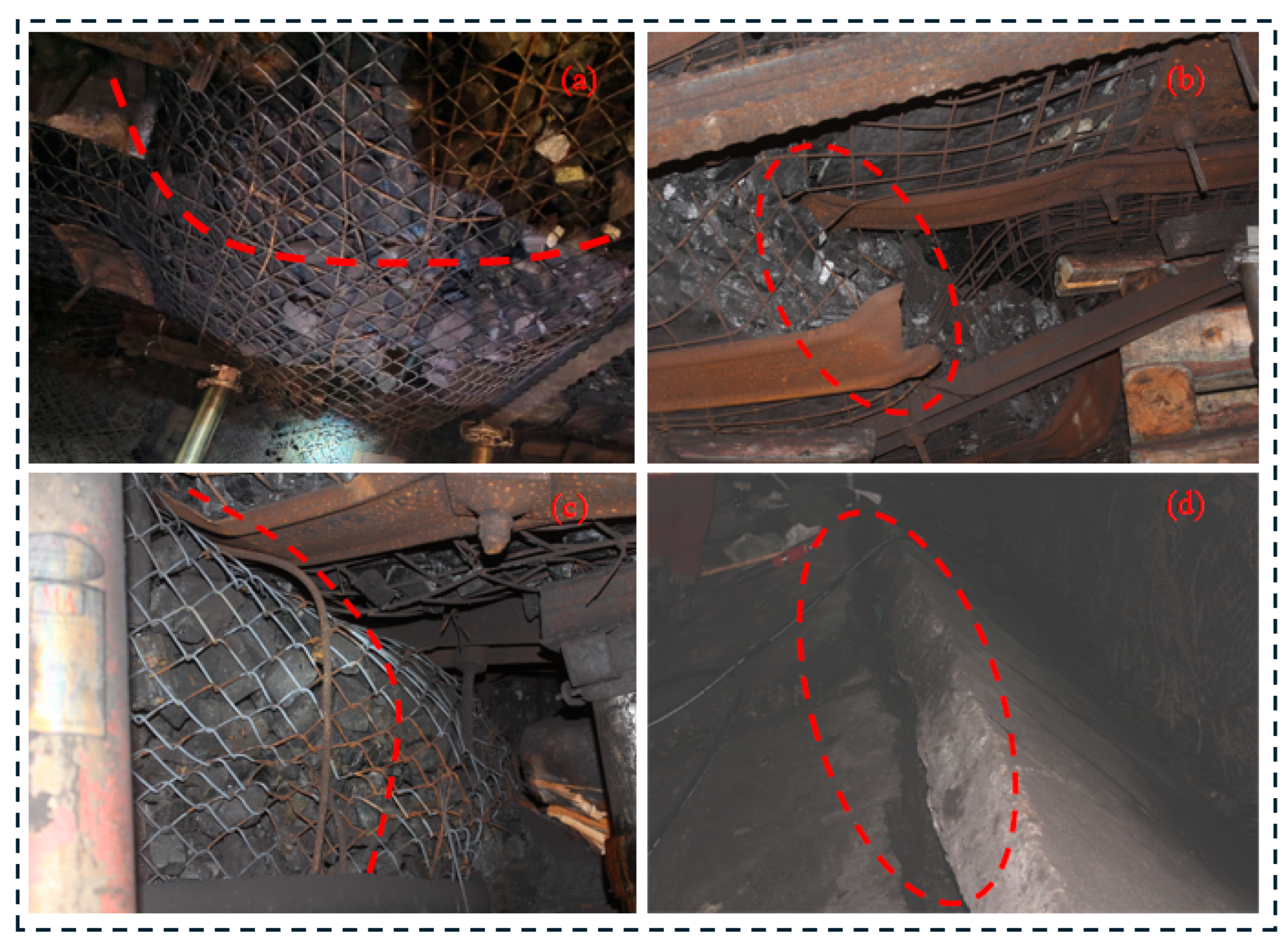
When a 30 m coal pillar is left in the return airway of the 8201 working face, the roadway surrounding rocks experience severe deformation failure (Figure 2). Roadway roof is heavily fractured, with significant subsidence and noticeable mesh bagging phenomena. Numerous W-shaped steel straps on the roof are broken, and large-scale roof collapses even occur in some sections. Both roadway sides converge inward, exhibiting considerable deformation. Roadway floor is severely damaged, with intense and widespread floor heave. The roadway even shows a tendency to collapse and close entirely in some areas, which seriously compromises its stability and safe production.
Preliminary analysis suggests that the 30 m coal pillar might have placed the solid coal side precisely at or near the peak of the lateral abutment stress from the goaf. It results in the roadway being subjected to high abutment stress and severe failure. Therefore, mining the adjacent 8203 working face requires research on the reasonable coal pillar width for the roadway and corresponding surrounding rock control measures.

3. Overlying Strata Structure and Layout Principles of Gob-Side Roadways

3.1. Overlying Strata Structure in Gob-Side Roadways

The increased scale of the mining area significantly enlarges the goaf space in the fully mechanized caving face of extra-thick coal seams. The lower key overlying strata may fail to form a relatively stable articulated structure due to insufficient contact with waste rocks. In contrast, higher-positioned key strata above the cantilever beam can form a stable articulated structure. The occurrence conditions of key strata and their post-fracture movement affect the ground pressure behavior in the lower mining area and adjacent roadways [24,25]. The lateral structure of the working face studied in the paper is the final state after the mining activity completed and the overlying rock structure stabilized. The 8203 working face is overlain by multiple thick and hard key strata. Therefore, the primary issue is determining the structural form of these key strata after the extraction of the underlying coal seam. If rotation angle Δ generated during the fracturing process of the overlying strata exceeds maximum rotation angle Δmax for maintaining stability, a cantilever beam structure forms [26,27,28]. The critical condition for determining whether a cantilever beam structure can form is based on the rotation of the fractured rock strata Equation (1).
Δ > Δ m a x
Rotation angle Δ of the fractured rock strata is defined by Equation (2).
Δ = M 1 η a ( K p 1 )
where M is the thickness of the coal seam, unit: m; η is the loss rate of coal release; a is the thickness of the immediate roof, unit: m; K p is the bulking factor of collapsed immediate roof. The overlying key strata interlock and form a stable structure after fracture. Based on the mechanical model of key strata, Δmax of the cantilever beam is defined by Equation (3) [29].
Δ m a x = H q l 2 k H σ c
where H is the thickness of the key stratum, m; q is the overburden load on the key stratum, MPa; l is the periodic weighting interval of roof, m; σ c is the compressive strength of the key stratum, MPa; k is a dimensionless coefficient. The condition required for the key stratum in an extra-thick coal seam to form a cantilever beam under mining conditions is Equation (4).
M ( 1 η ) a ( K p 1 ) > H q l 2 k H σ c
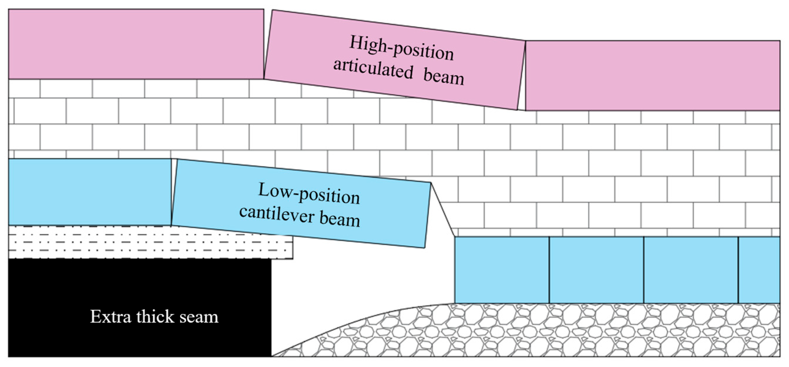
According to the geological conditions of the 8203 working face, the loss rate during coal release is set at 15%, with a bulking factor of immediate roof of 1.2, a periodic weighting interval of 19.7 m, the key stratum’s compressive strength of 57.01 MPa, dimensionless coefficient k of 0.85, the overlying strata’s unit weight of 25 kN/m3, the average burial depth of 382 m, and an overburden load of 9.55 MPa. Rotation amount Δ is 17.05 m by substituting above data into Equation (2). Δmax of the stable structure is 6.37 m by substituting into Equation (3). Δ > Δmax, indicating that the lower key stratum can form a cantilever beam structure after coal extraction. In summary, the overlying strata of the fully mechanized caving face in extra-thick coal seams will form a combined structural configuration consisting of a low-position cantilever beam and a high-position articulated rock beam (Figure 3).

3.2. Fracture Location of the Main Roof Cantilever Beam

For the ground pressure behavior of gob-side roadways, the cantilever beam structure has a direct influence. The fracture length of the cantilever beam is calculated using Equation (5) [30]. The formula is the relationship formula between the length of main roof lateral fracture block and the length of the working face based on the study of the ultimate fracture span of the main roof rock layer and from similar laboratory experiments.
L 0 = l l s 2 + 3 2 l s
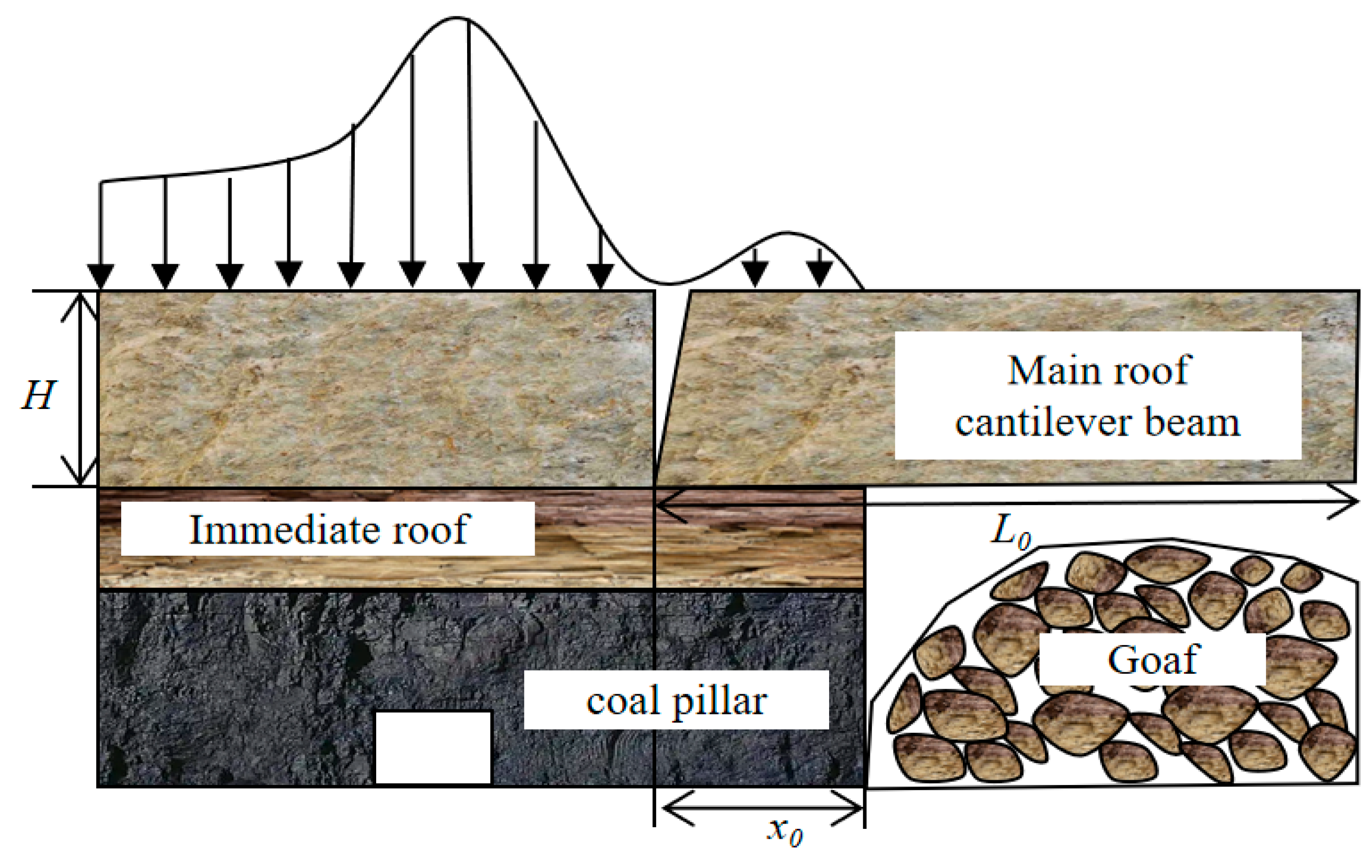
where s represents the length of the upper section working face (220 m). L 0 = 23.45 m after substitution. The fracture position of the cantilever beam is deduced using the theory of internal and external stress fields (Figure 4).
Assuming that the coal body is based on linear elasticity, the use of elastic constitutive theory can easily determine the pressure bearing capacity of coal under given deformation conditions, which is beneficial for the derivation of mathematical formulas. The vertical stress exerted on the coal body at distance x from the coal wall is defined by Equation (6) [31].
σ y = G x y x
where σ y represents the vertical stress experienced by coal at position x, N/m; G x represents coal stiffness, GPa/m; y x represents the coal compression, m.
Coal stiffness and compression within the internal stress field are assumed to vary linearly (Equation (7)).
y x = y 0 x 0 ( x 0 x ) G x = G 0 x 0 x
where y 0 represents the coal compression at the coal wall, m; x 0 represents the width of the internal stress field, m; G 0 represents coal stiffness at the coal wall, GPa/m.
Vertical concentrated force F in the internal stress field is defined as Equation (8) by combining Equations (6) and (7).
F = 0 x 0 σ y d x = G 0 y 0 x 0 6
The vertical abutment pressure within the internal stress field is approximately equal to the weight of the overlying strata controlled by the cantilever beam and articulated rock beam structure. Therefore, the abutment pressure in the internal stress field is defined by Equation (9).
F = s 1 n h i L γ
where 1 n h i represents the combined height of the cantilever beam and articulated rock beam structure, m; L represents the periodic weighting interval of the working face, m; γ represents the unit weight of main roof, kN/m3.
The relationship between y 0 and x 0 is defined by Equation (10).
y 0 x 0 = Δ L 1
where L 1 represents the suspended span of the rock beam, approximately equal to its breaking length L 0 .
Coal compression is defined as Equation (11) by combining Equations (2) and (10).
y 0 = x 0 L 0 M ( 1 η ) a ( K p 1 )
Coal stiffness G0 is defined as Equation (12) under plastic conditions.
G 0 = E 2 ( 1 + u ) ξ
where E represents the elastic modulus of coal, GPa; ξ represents the integrity coefficient of coal; u represents Poisson’s ratio of coal. The final range of the internal stress field ( x 0 ) is derived as Equation (13) by combining Equations (1)–(12).
x 0 = 6 γ s l 1 n h i L G 0 [ M ( 1 η ) a ( K p 1 ) ]
Based on available geological data, structural thickness is taken as 90 m, with an initial weighting interval of 50 m, an integrity coefficient of 0.75, an elastic modulus of 5.21 GPa, a Poisson’s ratio of 0.39, and a unit weight of 25 kN/m3. Finally, x 0 is 15.4 m after calculation.

3.3. Layout Principle of Gob-Side Roadways

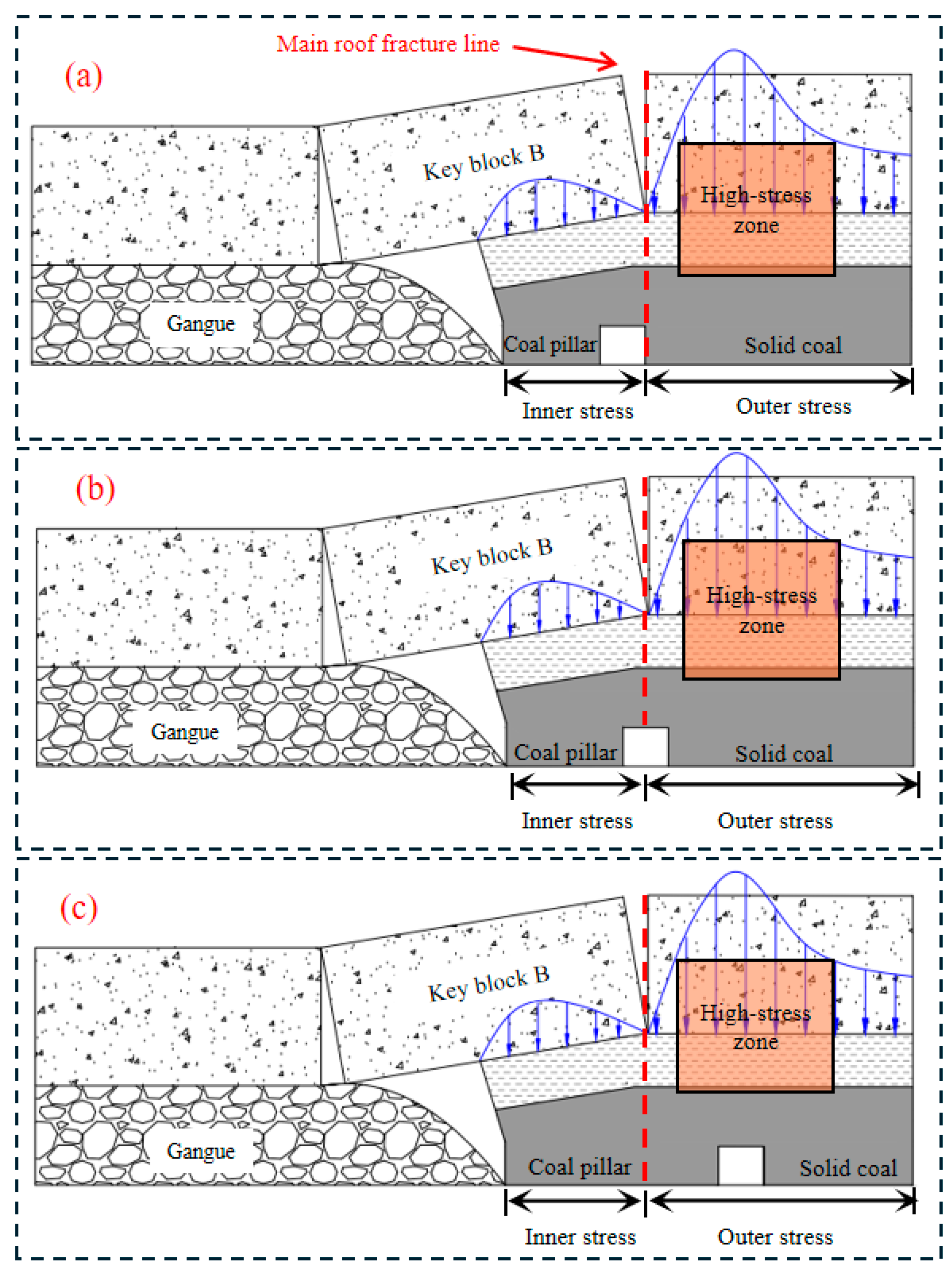
The rational layout of the gob-side roadway is crucial for the safe production of coal mines. The relative position between the roadway and the fracture line of main roof directly affects the roadway stability and the overall production environment of the mine. Based on the positional relationship between the main roof fracture line and the roadway, the roadway positions are categorized into three types (Figure 5). (a) Fracture line above solid coal. The key block is supported by gangue, coal pillar, and solid coal. The key block remains relatively stable with minimal rotational subsidence, which makes this a reasonable roadway layout. (b) Fracture line above the roadway. The key block is supported only by gangue and coal pillar. The key block of main roof undergoes severe rotational subsidence due to the limited load-bearing capacity of the coal pillar. The roadway experiences intense deformation, which poses a significant threat to mine safety. Therefore, positioning the roadway directly beneath the main roof fracture line should be avoided. (c) Fracture line above the coal pillar. The movement of the main roof key block has little impact on the roadway. However, the roadway is located in a high-stress zone, carrying a risk of severe deformation.
In summary, positioning the roadway within the internal stress field range of the main roof fracture line is the optimal location. Considering a roadway width of 5.5 m and a calculated internal stress field range of 15.4 m, the maximum allowable width of the coal pillar to ensure roadway stability and safety should not exceed 9.9 m.

4. Bearing Characteristics of Deteriorated Coal Pillars in Gob-Side Roadways

Based on the actual production and geological conditions of the 8203 working face, simulation software FLAC3D 6.0 was used to study the bearing characteristics of deteriorated coal pillars in gob-side roadways. This was achieved by analyzing the distribution of stress, plastic zones, and zero-displacement surfaces in surrounding rocks of coal pillars with different widths during the gob-side roadway driving process. The model had a length of 430 m along the dip direction, 250 m along the working face advance direction, and a height of 50 m. The bottom and side boundaries of the model were set as fixed constraints, and rock mass was modeled using the Mohr-Coulomb criterion. The overlying strata load on the model was 7.803 MPa. Horizontal stress was applied to the four sides of the model, with a lateral pressure coefficient of 1.2. The mechanical parameters of the surrounding rocks measured in the laboratory were modified based on the Hoek-Brown empirical strength criterion (Table 1). This model did not take into account the creep characteristics of the rock mass because its focus was on the stress and plastic zone changes of the surrounding rock after the disturbance of the underground rock mass caused by mining.

4.1. Stress Distribution Characteristics of Roadway Surrounding Rocks

The simulation covers six scenarios with coal pillar widths of 4, 6, 8, 10, 12, and 14 m, respectively. The simulation process strictly adheres to actual engineering procedures. First, the model is established and brought to an initial equilibrium state, followed by resetting the velocity and displacement fields. Subsequently, the excavation of the 8201 haulage way and the 8201 working face is simulated, along with the driving of the 8203 return airway. The dimensions of the roadway are 5.5 m in width and 3.5 m in height.
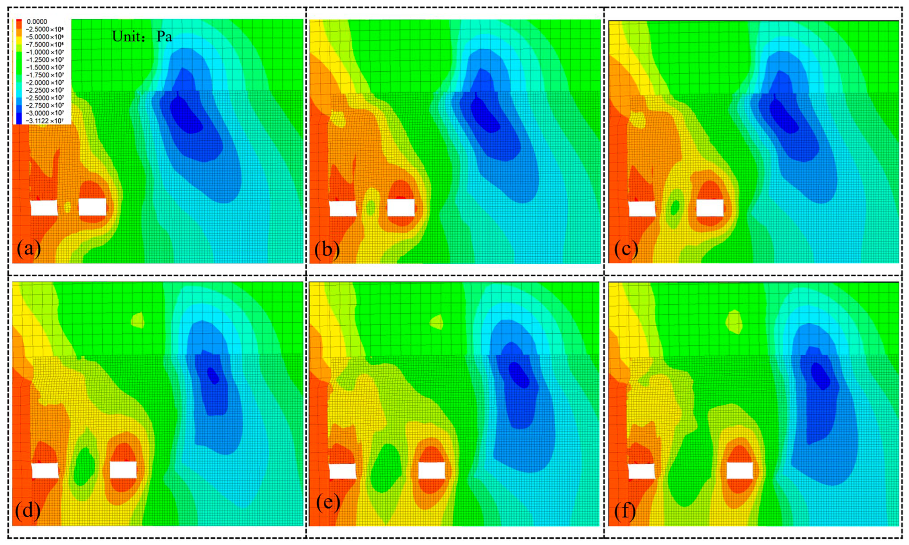
Figure 6 and Figure 7 resent simulated vertical stress distribution in the surrounding rocks and the internal stress curves of coal pillars under different pillar widths during excavation. (1) The peak stress inside the coal pillar gradually increases at the pillar widths of 4–14 m as the pillar width grows. The variation in pillar width directly influences its internal stress distribution, which affects the load-bearing capacity and stability of the pillar. (2) When the pillar width is 4 or 6 m, the stress within the pillar remains lower than the in situ rock stress. Coal mass undergoes severe damage due to lateral abutment pressure. The load-bearing capacity is significantly restricted and diminished in such weakened pillars. (3) Once the pillar width reaches or exceeds 8 m, the internal stress of the pillar exceeds the in situ rock stress. The volume of coal experiencing stresses higher than the in situ rock stress expands as the width further increases. The load-bearing capacity is notably enhanced in wider pillars.

4.2. Distribution Characteristics of Plastic Zones in Roadway Surrounding Rocks

Figure 8 shows the distribution of plastic zones in the surrounding rock of roadways under different coal pillar widths. (1) Roadway surrounding rocks are subjected to extensive damage due to intense mining-induced disturbances from the working face. Most of the coal pillar and the roof strata are in a plastic failure state, while roadway floor, being stronger than the coal seam, exhibits a smaller failure zone. (2) The damaged zone in the coal seam extends up to 25 m from the coal wall. As the pillar width increases, the plastic zone on the solid coal side of the roadway gradually expands. A wider pillar causes the roadway to penetrate deeper into the solid coal, which enlarges the plastic zone. In summary, ultra-thick coal seam mining induces wide-range plastic failure in surrounding rocks. When a deteriorated coal pillar is retained for the gob-side roadway, the entire pillar remains within the plastic failure zone.

4.3. Distribution Characteristics of Plastic-Bearing Zones in Coal Pillars

Rational coal pillar width should be determined by the widths of the plastic zones on both sides and the elastic bearing zone in the middle. The stability of the coal pillar largely depends on the width of the elastic bearing zone, as this zone bears the majority of the overlying load and serves as the core of the coal pillar. However, the weakened coal pillar is left in the gob-side roadway during the mining of extremely thick coal seams. The rapid deformation and failure of the coal pillar significantly reduce its overall load-bearing capacity due to intense dynamic pressure effects. This process causes the entire weakened coal pillar to enter a fully plastic state. Nevertheless, coal in the plastic state still retains some bearing capacity.
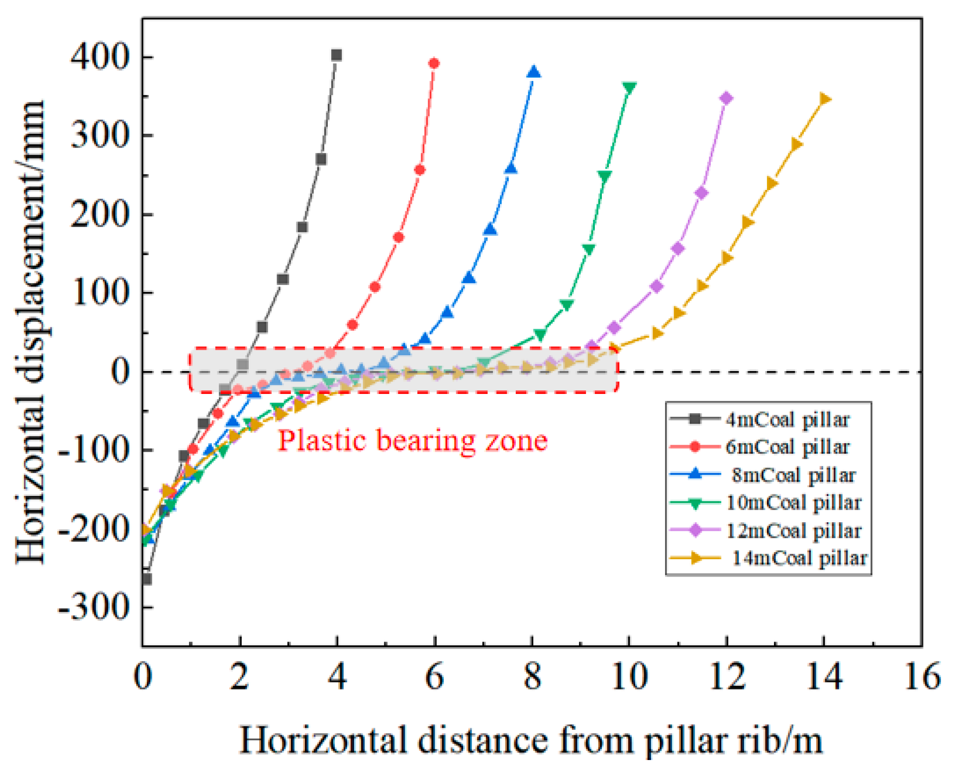
There exists an area within the weakened coal pillar where horizontal displacement is negligible or absent. Surrounding coal in this area is subjected to a triaxial compressive state due to mutual squeezing. This region is referred to as the zero-displacement plane or the plastic-bearing zone. Its appropriate width is crucial for ensuring the stability of the coal pillar, as it serves as the primary load-bearing body for the overlying strata [32,33].
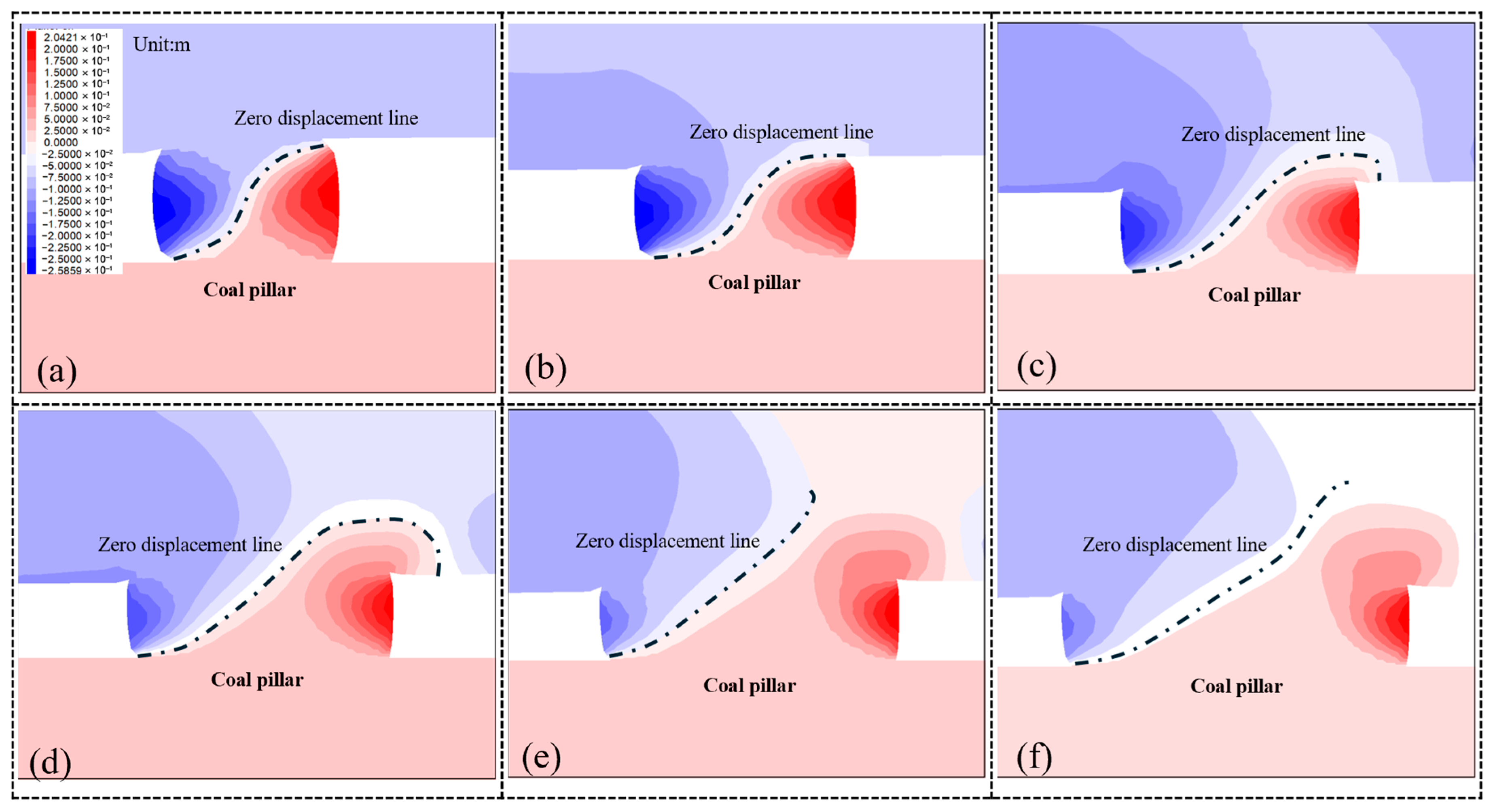
Figure 9 and Figure 10 show the contour plots of the zero-displacement plane and the distribution curves of horizontal displacement inside coal pillars with different widths. The internal stress distribution and displacement of coal pillars with varying widths follow similar patterns. The zero-displacement plane in the roof of the coal pillar shifts toward the roadway side, while that in floor shifts toward the goaf. This displacement indicates that the coal pillar undergoes compressive deformation under vertical stress. The zero-displacement plane consistently deviates toward the roadway side rather than aligning with the coal pillar center under different coal pillar widths. The movement of overlying strata in the gob-side area subjects coal on the goaf side to higher stress and deformation, which leads to more severe damage.
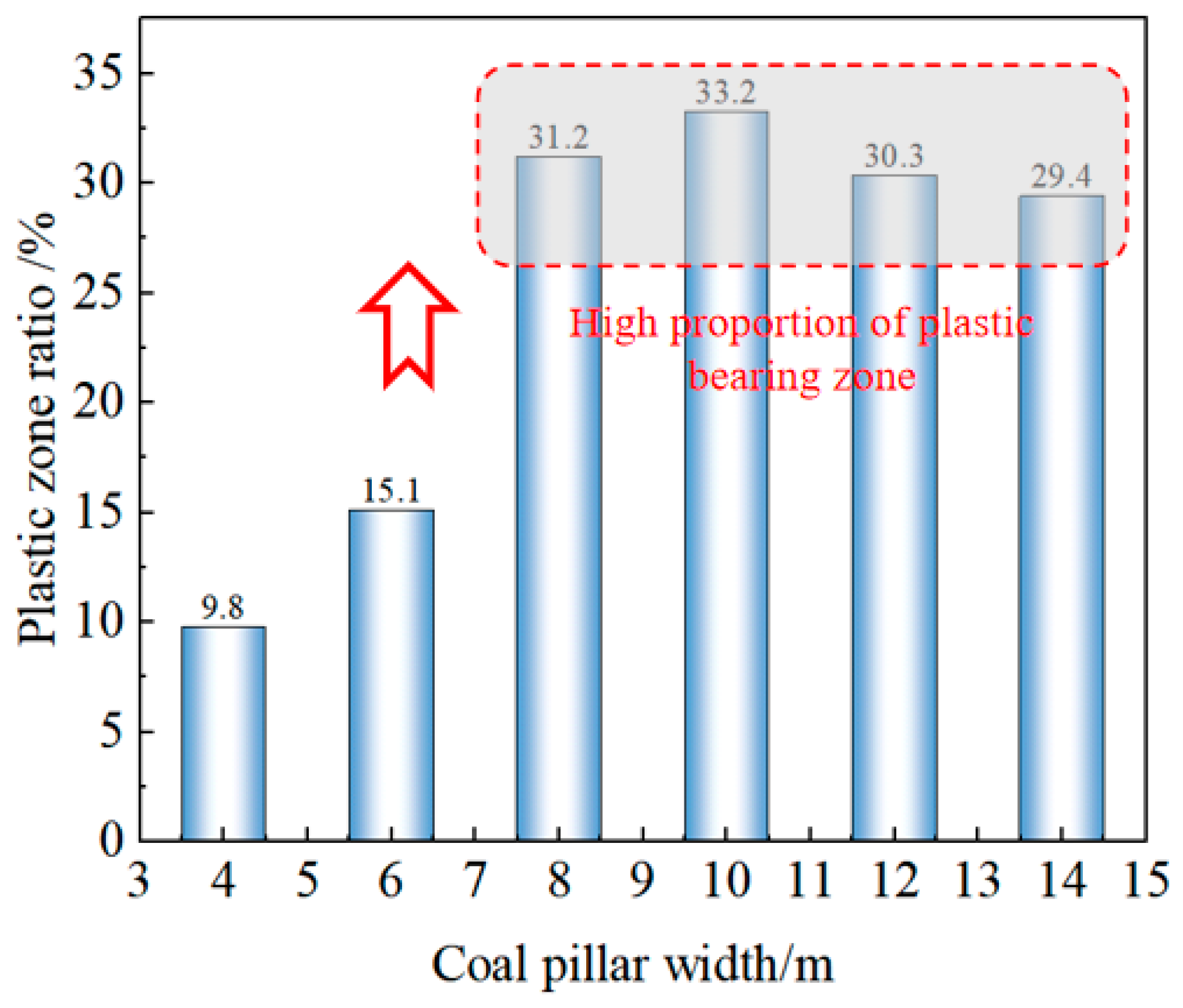
As observed in Figure 11, the following conclusions can be drawn. (1) When the coal pillar width is 4 or 6 m, the occupancy rate of the plastic-bearing zone remains at a relatively low level with limited growth. Fractured zones on both sides of the coal pillar—due to stress concentration and the limited strength of the coal mass—tend to expand toward the center and eventually interconnect. Consequently, narrower coal pillars exhibit weaker stability and load-bearing capacity. (2) A significant change occurs when the coal pillar width increases to 8 or 10 m. Both the occupancy rate and width of the plastic-bearing zone show a marked increase. This change strengthens the overall structural integrity of the coal pillar and improves its ability to support the overlying strata’s weight and stress. Therefore, moderately increasing the pillar width can substantially improve its load-bearing capacity, which enhances roadway stability and safety. (3) When the coal pillar width further increases to 12–14 m, the width of the plastic-bearing zone continues to expand. However, the occupancy rate of this zone decreases. The coal pillar, positioned at the fracture point of the cantilever beam, bears the weight of higher-level strata and stresses transmitted from the internal stress field. As a result, despite having a larger plastic-bearing zone, the improvement in load-bearing capacity is constrained.
According to the analysis of the internal stress and plastic-bearing zone of the coal pillar, the stress level and proportion of plastic-bearing zone of 8 m and 10 m coal pillars are suitable choices. Under this premise, from the perspective of coal resource recovery, that is, from an economic perspective, the smaller the width of the coal pillar left, the more coal resources can be recovered, and the better the economic benefits. Therefore, compared with the 10 m coal pillar, the advantages of the 8 m coal pillar are more obvious, and it is the most reasonable coal pillar width.

5. Deformation Law of Surrounding Rocks in Gob-Side Roadways

Figure 12a shows roof displacement variation in the vertical direction within coal pillars of different widths. (1) The right side of the figure represents the coal pillar side, where the roof deformation is significantly greater than that on the solid coal side. Overlying strata use the coal pillar as a fulcrum during fracture and rotation, which subjects it to intense compression and results in severe compressive deformation. Additionally, the fracture and rotation of the overlying strata cause asymmetric subsidence due to structural adjustments in the roof strata [34]. (2) As the coal pillar width decreases, the roof subsidence displacement increases. When the coal pillar width is reduced from 14 to 4 m, the maximum roof displacements are 272, 286, 318, 288, 325, and 348 mm, respectively. The reduction in coal pillar width exacerbates the asymmetric subsidence of roof. As the coal pillar narrows, its load-bearing capacity declines, which increases subsidence on the coal pillar side of roof.
There is a close relationship between coal pillar width and side deformation in Figure 12b,c. Specifically, as the coal pillar width decreases from 14 to 4 m, the maximum deformation of the coal pillar sides increases to 168, 184, 195, 210, 240, and 269 mm, respectively. However, that of the solid coal sides reaches 129, 139, 142, 152, 174 mm, and 184 mm, respectively. As the coal pillar width gradually decreases, the deformation of both sides rapidly increases. Therefore, changes in coal pillar width significantly affect side deformation. Additionally, the deformation of the coal pillar side is notably greater than that of the solid coal side, demonstrating obvious asymmetry.

6. Surrounding Rock Control Scheme of the Asymmetric Truss Anchor Cables

6.1. Roadway Support Parameters

The 8203 return airway has a cross-section width of 5.5 m and a height of 3.5 m. When the deformation on the coal pillar side is greater than that on the solid coal side, an asymmetric truss anchor cable support scheme is designed for the roadway. Figure 13 shows detailed specifications [35].
(1) Roof support scheme: The rock bolts consist of 7 threaded steel bolts with a length of 3100 mm and a diameter of 20 mm, spaced at 850 × 800 mm intervals. The bolts are connected using steel bar ladder beams, with the middle 5 bolts installed perpendicular to roof. The remaining two bolts on each side are angled outward by 15°. The anchor cables consist of 5 prestressed steel strands with a length of 8250 mm and a diameter of 17.8 mm, spaced at 1200 × 1600 mm intervals. The anchor cables are connected using W-shaped steel straps. The two side anchor cables are angled outward by 15°, while the remaining 5 anchor cables are installed perpendicular to roof.
Asymmetric truss anchor cable: The anchor cables consist of 3 prestressed steel strands, each with a length of 8250 mm and a diameter of 17.8 mm. The cables are connected using a 3400 mm-long 16# channel steel featuring drilled holes (150 × 25 mm) and thick steel washers (hole diameter: 25 mm). The anchor cables in the middle and near the coal pillar side are positioned 2200 and 900 mm from the coal pillar side, respectively. In addition, that near the solid coal side is 1500 mm from solid coal. The anchor cables on the two sides are angled outward by 15°, while the middle anchor cable remains perpendicular to roof.
(2) Coal pillar side support scheme: The bolts selected are 4 threaded steel bolts with a length of 3100 mm and a diameter of 20 mm. The bolts are connected using steel bar ladder beams, arranged at a spacing of 1000 × 800 mm. The bolts near roof and floor are rotated 15° upward and downward, respectively, while the other two bolts are perpendicular to the coal pillar side. The anchor cables selected are 3 prestressed steel strands with a length of 5250 mm and a diameter of 17.8 mm, arranged at a spacing of 1200 × 800 mm. The anchor cables near roof and floor are rotated 15° upward and downward, respectively, while the remaining one is perpendicular to the coal pillar side.
(3) Solid coal side support scheme: The bolt support arrangement for the solid coal side is the same as that for the coal pillar side. The anchor cables selected are 2 prestressed steel strands with a length of 5250 mm and a diameter of 17.8 mm, arranged at a spacing of 2400 × 800 mm. The anchor cables near roof and floor are inclined 15° upward and downward, respectively.

6.2. Characteristics of the Support Structure’s Prestress Field

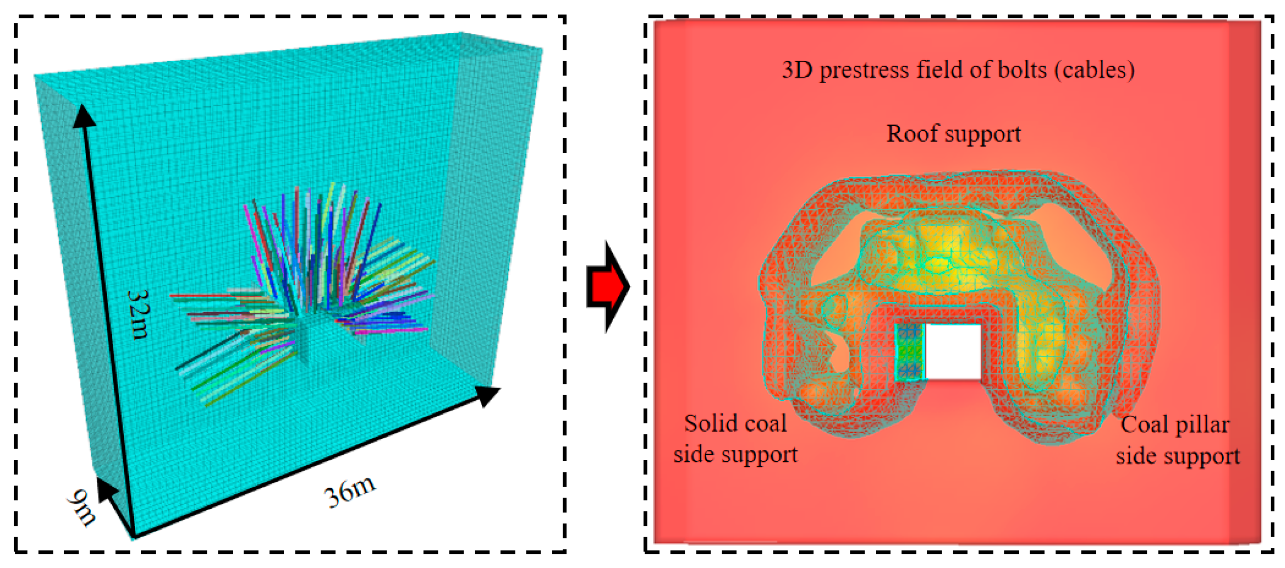
The prestress field characteristics of the roadway bolt (cable) support system are simulated at a 1:1 scale using FLAC3D. This simulation is to verify the control effect of bolt (cable) support on surrounding rocks in the gob-side roadway with deteriorated coal pillars in extra-thick coal seams. Accordingly, simulation units for bolts, cables, and their corresponding trays are established. The pre-tension force of 120 and 80 kN is applied to the cables and bolts, respectively. The model dimensions are 36 × 9 × 32 m (L × W × H), with a roadway cross-section of 5.5 × 3.5 m (W × H) (Figure 14). Due to the fact that the model does not apply geo-stress and only applies pre-tension force to the anchor rods and cables, there will be no significant displacement at the boundary of the model. Therefore, the model edge constraints will not have a significant impact on the stress field. The morphology of the 3D prestress field isopotential surfaces reveals that the range and volume of the prestress field in roadway roof are larger than those in the two sidewalls. In addition, the prestress field range and volume on the coal pillar side are greater than those on the solid coal side.
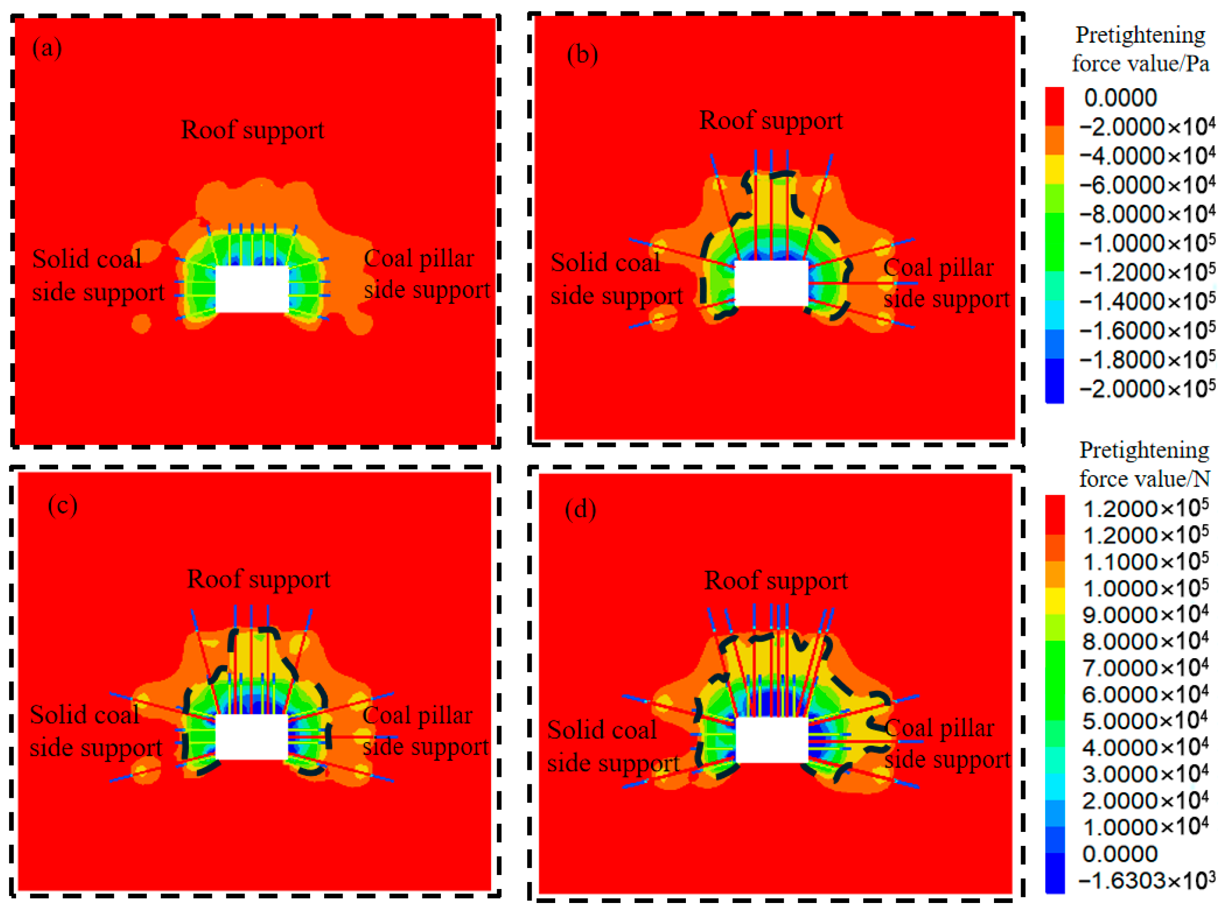
The stress distribution characteristics of the bolt cross-section in roof and both sides exhibit higher stress values on the coal pillar side compared to the solid coal side under the superimposed prestress from asymmetric truss cables and differentiated sidewall cables (Figure 15). The stress on the right-side roof and coal pillar side exceeds 0.14 MPa in the shallow surrounding rocks of the roadway, with interconnected stress zones. Only the shoulder and floor corners exhibit relatively high stresses (approximately 0.13 MPa) on the solid coal side. The prestress can reach 0.05 MPa in the surrounding rocks within the bolt length range. Similarly, stress distribution in the cable cross-section shows higher values on the coal pillar side than on the solid coal side, with the effective support stress (0.05 MPa) extending into roof. The stresses in the roof and coal pillar side exceed 0.15 MPa in the shallow surrounding rocks, with interconnected stress zones forming. Only the shoulder and floor corners exhibit higher stresses (0.14 MPa) on the solid coal side.
The cross-sectional stress distribution characteristics between bolts and cables show more pronounced stress concentration on the coal pillar side compared to the solid coal side. The effective support stress (0.05 MPa) extends into the coal pillar side, demonstrating an obvious asymmetric reinforcement effect. That is, the support strength on the coal pillar side is significantly greater than that on the solid coal side. The stresses in roof and on the coal pillar side exceed 0.16 MPa in the shallow surrounding rocks of the roadway, with interconnected high-stress zones forming. In contrast, only the shoulder and floor corners exhibit elevated stresses (0.15 MPa) in the shallow part of the solid coal side.
The stress distribution characteristics of the truss anchor cable cross-section exhibit the most significant stress concentration on the coal pillar side compared to the solid coal side. The effective support stress (0.05 MPa) extends toward the shoulder corner. The stresses in roof and on the coal pillar side exceed 0.18 MPa in the shallow surrounding rocks, with an expanded interconnected high-stress zone. In contrast, the support stress on the solid coal side shows no significant variation. In conclusion, the asymmetric control scheme using truss anchor cables in the gob-side roadway demonstrates a powerful reinforcing effect on surrounding rock stability.

7. Engineering Practice

The coal pillar between the return airway of the 8203 and 8205 working face and the goaf is designed to be 8 m wide. Roadway surrounding rocks are controlled according to the aforementioned support scheme. The 8203 working face was mined first, followed by the 8205 working face. A monitoring station was set up 60 m ahead of the working face during the mining of the 8203 and 8205 working face to measure the deformation of roadway surrounding rocks. Data are compared with the deformation data of the return airway during the mining of the 8201 working face in Figure 16a.
When the monitoring station is approximately 60 m away from the working face, the deformation of the surrounding rocks increases. The deformation rate of the surrounding rocks is relatively slow in the range of 60 to 30 m from the working face. The deformation rate accelerated until reaching its maximum in the range of 30 to 0 m. The final convergence of the roof and floor of the 8203 return airway is 257 mm, a 53% reduction compared to that of the 8201 return airway. The final convergence of the two sides is 330 mm, a 52% reduction compared to that of the 8201 return airway; The final convergence of the roof and floor of the 8205 return airway is 284 mm, a 47% reduction compared to that of the 8201 return airway. The final convergence of the two sides is 306 mm, a 56% reduction compared to that of the 8201 return airway. Existing research has shown that as the distance from the working face increases, the influence of advanced support pressure on the working face becomes greater, and the deformation of the roadway becomes more severe. Ultimately, the reasonable deformation of the surrounding rock of the roadway is controlled within the range of 200–300 mm [36,37]. Surrounding rock deformations in the 8203 and 8205 return airway remain within a controllable range, without affecting the normal mining operations of the working face.
Figure 16b shows the field roadway in original support and asymmetric support. The roof of the original supported roadway has undergone significant asymmetric deformation with severe coal pillar side subsidence. The roadway cross-section remains intact after asymmetric support, with no significant deformation of the surrounding rock and no failure of the support structure. This further verifies the rationality and effectiveness of the designed deteriorated coal pillar width and the asymmetric support system.

8. Conclusions

(1)
Key strata above the goaf of the fully mechanized caving face in the extra-thick coal seam formed a structure of low-level cantilever beam and high-level articulated rock beam. The calculated breaking position of the main roof cantilever beam was 15.4 m from the coal wall of the goaf. The optimal location for the roadway was within the inner stress field inside the main roof fracture line. Therefore, the maximum width of the reserved coal pillar should not exceed 9.9 m.
(2)
When the coal pillar width ranged from 4 to 14 m during roadway excavation, each width exhibited a stress peak. This peak increased as the coal pillar widened. When the pillar width reached 8 m, the internal stress exceeded the in situ rock stress. In addition, the entire coal pillar entered a fully plastic failure state.
(3)
The occupancy rate of the plastic-bearing zone was higher than that in pillars with other widths within the 8–10 m of deteriorated coal pillars. Considering safety and economic factors, the optimal width for the gob-side roadway was determined to be 8 m. Roof subsidence and deformation on the coal pillar side were greater than those on the solid coal side, demonstrating obvious asymmetric deformation in the roadway.
(4)
An asymmetric support scheme using truss-anchor cables was proposed. Numerical simulations confirmed that the selected support system established a prestressed field in the surrounding rocks. Field practice further verified the rationality and effectiveness of the designed deteriorated coal pillar width and the asymmetric support system.

Author Contributions

J.J.: Conceptualization, Methodology, Formal analysis, Supervision; Y.W.: Software, Writing—Original draft; X.J.: Validation; F.Q.: Investigation. All authors have read and agreed to the published version of the manuscript.

Funding

The Science and Technology Plan Project of Datong (No: 2024002, No: 2024013).

Institutional Review Board Statement

Not applicable.

Informed Consent Statement

Not applicable.

Data Availability Statement

The original contributions presented in this study are included in the article. Further inquiries can be directed to the corresponding author.

Conflicts of Interest

The authors declare no conflicts of interest.

References

  1. Zhu, L.Z.; Song, H.R.; Lu, Y.L. Research on mechanical mechanism and control technology of mine pressure appearance in gob-side entry driving of extra-thick coal seam. Coal Technol. 2025, 44, 87–93. [Google Scholar]
  2. Cheng, K.H.; Wang, P.F.; Zhai, L.W. Research and application of anchor cable support technology for whole coal roadway in isolated working face of extra-thick coal seam. Saf. Coal Mines 2021, 52, 106–114. [Google Scholar]
  3. Xing, X.D. Application research on key technology of reasonable arrangement of small coal pillar in extra-thick coal seam. Coal Technol. 2025, 44, 46–50. [Google Scholar]
  4. Wang, X.G.; He, H.; Zang, S.F.; Xue, S.H.; He, Y.K.; Niu, X.; Luo, Y. Integrated pressure relief technology for rock burst and gas outburst coordinated control in ultra-thick coal seams under spatially isolated rock pillar areas. Saf. Coal Mines 2025, 56, 69–77. [Google Scholar]
  5. Feng, J.; Wang, K.; Chen, J.; Liu, Y.; Zheng, X.; Niu, K. Design of the Appropriate Width of the Filling Body for Gob-side Entry Retaining in Hard and Thick Top Coal with Gangue Concrete. Acad. J. Archit. Geotech. Eng. 2025, 7, 39–49. [Google Scholar]
  6. Pan, K.; Ju, J.W.; Hou, B.; Jia, H.-S. An exploration of improving stability of gob-side entry retained with graded and zoned pressure relief technology: A case study. Sci. Rep. 2024, 14, 29440. [Google Scholar] [CrossRef] [PubMed]
  7. Zhang, Q. Mechanism and control of asymmetric floor heave in gob-side entry under dynamic pressure in ultra-thick coal seams. Coal Eng. 2025, 57, 44–53. [Google Scholar]
  8. Li, H.M.; Wang, W.Q.; Wang, Z.G.; Sun, H. Surrounding rock control technology with synergetic support and pressure relief for gob-side entry driving in extra-thick coal seam. Coal Eng. 2024, 56, 45–51. [Google Scholar]
  9. Liu, Y.; Yang, Y.; Wang, X.; Wang, W.Q.; Wu, X.S.; Cao, X.Y.; Lu, Z.J.; Yang, T.; Wei, Z.Q. Instability mechanism of coal pillar in steeply dipping ultra-thick coal seam “segmented and stratified” combined mining. Saf. Coal Mines 2025, 56, 146–154. [Google Scholar]
  10. Chen, Z.M.; Li, Z.L.; Zhong, T.P.; Song, D.Z.; Liu, X.D.; Hu, X.C. Numerical simulation study on mining method for anti rock burst in different steeply inclined extra-thick coal seam. Saf. Coal Mines 2025, 56, 117–127. [Google Scholar]
  11. Zhao, W.Z.; Xi, B.P.; Han, F.Z.; Fan, Q.; Jiang, Y.C. Research on the coal pillar width of gob-side entry driving in fully mechanized caving face in extra thick coal seam. China Coal 2024, 50, 140–147. [Google Scholar]
  12. Liu, Y.; Guo, W.; Fan, G.; Yu, W.; Chai, Y.; Yue, X.; Han, X. Research on Key Roof-Cutting Parameters for Surrounding Rock Stability Control in Gob-Side Entry Retention without Coal Pillars in Karst Mountainous Area. Appl. Sci. 2024, 14, 8118. [Google Scholar] [CrossRef]
  13. Zhao, M.Y.; Zhu, L.; Huang, Q.X.; Xu, K.; Wu, Y.; Gu, W. Research on Roof Fracture Characteristics of Gob-Side Entry Retaining with Roof Cutting and Non-pillar Mining in Thick Coal Seam, China. Geotech. Geol. Eng. 2021, 40, 1–20. [Google Scholar] [CrossRef]
  14. Guo, H.J.; Liu, H. Research on the reasonable width of coal pillar in fully mechanized caving mining section in extra-thick coal seam. China Coal 2024, 50, 231–237. [Google Scholar]
  15. Zhao, G.Z.; Ma, Z.G.; Sun, K.; Fan, J.-Q.; Li, K. Research on deformation controlling mechanism of the narrow pillar of roadway driving along next goaf. J. Min. Saf. Eng. 2010, 27, 517–521. [Google Scholar]
  16. Bai, J.B.; Hou, C.J.; Huang, H.F. Numerical simulation study on stability of narrow coal pillar of roadway driving along goaf. Chin. J. Rock Mech. Eng. 2004, 23, 3475–3479. [Google Scholar]
  17. Zheng, X.G.; Yao, Z.G.; Zhang, N. Stress Distribution of coal pillar with gob-side entry driving in the process of excavation & mining. J. Min. Saf. Eng. 2012, 29, 459–465. [Google Scholar]
  18. Chen, Z.W.; Zhang, Y.D. Research and application of coordinated control technology for surrounding rock stability of gob-side entry driving with narrow coal pillar. Min. Saf. Environ. Prot. 2023, 50, 65–70. [Google Scholar]
  19. Zhang, G.C.; He, F.L. Rock and soil mechanics pillar width determination and surrounding rocks control of gob-side entry with large cross-section and fully-mechanized mining. Rock Soil Mech. 2016, 37, 1721–1728+1736. [Google Scholar]
  20. Li, W.; Bai, J.; Peng, S.; Wang, X.; Xu, Y. Numerical modeling for yield pillar design: A case study. Rock Mech. Rock Eng. 2015, 48, 305–318. [Google Scholar] [CrossRef]
  21. Shen, B. Coal mine roadway stability in soft rock: A case study. Rock Mech. Rock Eng. 2014, 47, 2225–2238. [Google Scholar] [CrossRef]
  22. Wu, W.; Wang, T.; Bai, J.; Liu, J.; Wang, X.; Xu, H.; Feng, G. Failure characteristics and cooperative control strategies for gob-side entry driving near an advancing working face: A case study. Processes 2024, 12, 1398. [Google Scholar] [CrossRef]
  23. Huang, W.; Zhao, T.; Zhang, C.; Liu, Y.; Sui, L.; Hou, T.; Jiang, D. Assessment of pillar stability and its control in a double roadway layout. Energy Sci. Eng. 2024, 12, 4192–4209. [Google Scholar] [CrossRef]
  24. Tomiczek, K. A brief analysis of behaviour possibility of a jointed rock mass near to longwall excavation face simulation using Distinct Elements Method (DEM) in the context of the Beam on Elastic Foundation (BEF) theory. In Proceedings of the E3S Web of Conferences, EDP Sciences, Milan, Italy, 13–15 February 2019; Volume 106, p. 01015. [Google Scholar]
  25. Wang, D.; He, F.; Wu, Y.; Lv, K.; Zhang, J.; Shi, S.; Guo, J.; Xu, X.; Tao, K.; Zhang, Y.; et al. Study on stability and control of surrounding rock in the large section stopping space with extra-thick coal seam. Alex. Eng. J. 2025, 117, 205–220. [Google Scholar] [CrossRef]
  26. Yan, S.H.; Yin, X.W.; Xu, H.J.; Xu, G.; Liu, Q.-M.; Yu, L. Roof structure of short cantilever-articulated rock beam and calculation of support resistance in full-mechanized face with large mining height. J. China Coal Soc. 2011, 36, 1816–1820. [Google Scholar]
  27. Yu, M.L.; Wang, Z.W.; Liu, Y.; Li, C.; Li, Z.; Wang, L. Mechanical mechanism of key strata fracturing under different water pressures in the fourth aquifer of loose layers. J. Min. Strat. Control. Eng. 2024, 6, 132–147. [Google Scholar] [CrossRef]
  28. Yu, M.L. Fracture Mechanics and Zoning Movement Model of Medium-Thick Strata in Coal Mines; China University of Mining and Technology: Beijing, China, 2023. [Google Scholar] [CrossRef]
  29. Zheng, Z.; Yang, Z.Q.; Zhu, H.Z.; He, F.L.; Du, C.Y.; Liu, B.Q. Study on reasonable coal-pillar width and surrounding-rock control of gob-side irregular roadway in inclined seam. J. Min. Saf. Eng. 2019, 36, 223–231. [Google Scholar]
  30. Zhang, G.C.; He, F.L. Asymmetric failure and control measures of large cross-section entry roof with strong mining disturbance and fully-mechanized caving mining. Chin. J. Rock Mech. Eng. 2016, 35, 806–818. [Google Scholar] [CrossRef]
  31. Wang, D.; He, F.; Wu, Y.; Xu, X.; Zhang, J.; Lv, K.; Li, L.; Zhai, W.; Song, J. Study on surrounding rock failure mechanism and rational coal pillar width of the gob-side coal roadway under influence of intense dynamic pressure. Energy Sci. Eng. 2023, 11, 1716–1733. [Google Scholar] [CrossRef]
  32. Xu, X.H.; He, F.L.; Li, X.B.; He, W. Research on mechanism and control of asymmetric deformation of gob side coal roadway with fully mechanized caving mining. Eng. Fail. Anal. 2021, 120, 105097. [Google Scholar] [CrossRef]
  33. Jiang, Z.S.; Chen, D.D.; Xie, S.R. A novel asymmetric stress unloading technology in two sides of coal roadway in deep mine: A case study. Tunn. Undergr. Space Technol. 2023, 142, 105452. [Google Scholar] [CrossRef]
  34. Zuo, J.P.; Ma, Z.Y. Asymmetric deformation and failure behavior of roadway subjected to different principal stress based on biaxial tests. Tunn. Undergr. Space Technol. 2025, 155, 106174. [Google Scholar] [CrossRef]
  35. Xie, S.R.; Ren, Y.X.; Chen, D.D.; Guo, W.; Li, S.; Li, Y.; Ma, X.; Ye, Q.; Chang, J.; Liang, D.; et al. A case study on coordinated asymmetric support-relief control for roadway surrounding rock under multiple dynamic pressures in thick coal seams. Eng. Fail. Anal. 2025, 179, 109821. [Google Scholar] [CrossRef]
  36. Qin, Z.; Liu, Y.; Zhang, F.; Liu, N. Stability Assessment of Gob Side Entry at the Steeply Inclined Mining Face. Appl. Sci. 2025, 15, 3244. [Google Scholar] [CrossRef]
  37. Zhang, H.; Wen, Y.; Wu, W.; Wen, H.; Hu, Y.; Wang, B.; Shao, J.; Li, Z.; Niu, J. Study on the Width of a Narrow Coal Pillar for Gob-Side Entry Driving near an Advancing Working Face in a Shallow Coal Seam. Energies 2025, 18, 4303. [Google Scholar] [CrossRef]
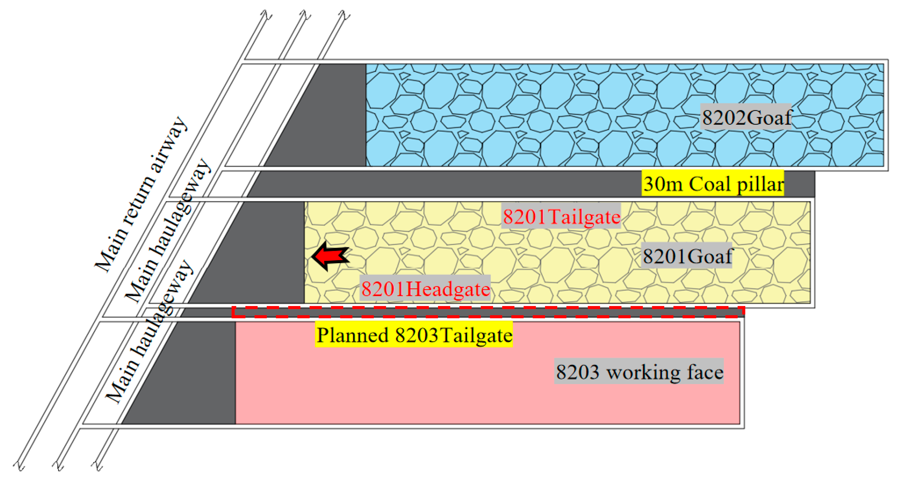
Figure 1. Relative position diagram of 8203 working face.
Applsci 15 10110 g001
Figure 2. Ground pressure manifestation along the goaf roadway: (a) excessive roof subsidence; (b) roof strap buckling; (c) rib spalling; (d) floor buckling.
Applsci 15 10110 g002
Figure 3. Structural characteristics of overlying rock layers on extra thick coal seams.
Applsci 15 10110 g003
Figure 4. Broken position of the cantilever beam.
Applsci 15 10110 g004
Figure 5. Position classification of gob-side roadways: (a) fracture line above solid coal; (b) fracture line above roadway; (c) fracture line above coal pillar.
Applsci 15 10110 g005
Figure 6. Cloud map of vertical stress distribution inside coal pillars of different widths: (a) 4 m; (b) 6 m; (c) 8 m; (d) 10 m; (e) 12 m; (f) 14 m.
Applsci 15 10110 g006
Figure 7. Distribution of vertical stress in coal pillars of different widths.
Applsci 15 10110 g007
Figure 8. Plastic zones in coal pillars of different widths: (a) 4 m; (b) 6 m; (c) 8 m; (d) 10 m; (e) 12 m; (f) 14 m.
Applsci 15 10110 g008
Figure 9. Zero displacement surface distribution inside coal pillars of different widths: (a) 4 m; (b) 6 m; (c) 8 m; (d) 10 m; (e) 12 m; (f) 14 m.
Applsci 15 10110 g009
Figure 10. Distribution of horizontal displacemen in coal pillars of different widths.
Applsci 15 10110 g010
Figure 11. The proportion of plastic-bearing zones.
Applsci 15 10110 g011
Figure 12. Deformation curves of surrounding rock in gob-side entry with different coal pillar widths: (a) roofs; (b) solid coal seams; (c) coal pillars.
Applsci 15 10110 g012
Figure 13. Support scheme for 8203 section return airway (unit: mm): (a) front view (b); top view.
Applsci 15 10110 g013
Figure 14. Model size and 3D prestressing field.
Applsci 15 10110 g014
Figure 15. Two-dimensional slice of stress field: (a) cross-section of bolt; (b) cross-section of cable; (c) cross-section between bolt and cable; (d) cross-section of truss cable.
Applsci 15 10110 g015
Figure 16. (a) Deformation of roadway surrounding rocks of the working face; (b) the cross-section of the roadway after support.
Applsci 15 10110 g016
Table 1. Mechanical parameters of 8203 working face surrounding rocks.
Rock StratumDensity
ρ/kg/m3
Internal Friction Angle φ/°Bulk Modulus
K/GPa
Shear Modulus
G/GPa
Cohesion
c/MPa
Siltstone24553210.27.73.98
Medium-coarse sandstone278035.912.48.519.10
Mudstone210230.13.82.532.58
Coal1521274.80.422.1
Sandy mudstone238030.94.43.413.2
Siltstone258032.710.57.518.5
Disclaimer/Publisher’s Note: The statements, opinions and data contained in all publications are solely those of the individual author(s) and contributor(s) and not of MDPI and/or the editor(s). MDPI and/or the editor(s) disclaim responsibility for any injury to people or property resulting from any ideas, methods, instructions or products referred to in the content.