Article

Finite Element Modeling and Analysis for Creep Buckling of a Cylindrical Shell Subjected External Lateral Pressure with Local Wall Thinning

1
School of Mechanics and Construction Engineering, Jinan University, Guangzhou 510632, China
2
CAS Key Laboratory of Mechanical Behavior and Design of Materials, University of Science and Technology of China, Hefei 230026, China
*
Authors to whom correspondence should be addressed.
Appl. Sci. 2025, 15(18), 10005; https://doi.org/10.3390/app151810005
Submission received: 8 August 2025 / Revised: 4 September 2025 / Accepted: 9 September 2025 / Published: 12 September 2025

Abstract

The corrosion, erosion, or worn defects on cylindrical shells often lead to localized wall thinning. The influence of the local wall-thinning defects on the creep buckling behavior of the cylindrical shells serving in high-temperature environments with high pressure is studied. A finite element model is developed for a Zircaloy cylindrical shell with two kinds of geometrical imperfections, including initial ovality and local wall thinning, which are the representations of the global and local geometric imperfections, respectively. Their influence on the creep buckling modes and the critical buckling time is investigated through the creep buckling analysis. It is revealed that the buckling modes are dominated by the ovality deformation in a wide range of defect widths, whether the initial ovality appears or not. The local thinning defects significantly reduce the critical buckling time of the cylindrical shells with initial ovality, where a 30% reduction was observed even with a small local defect, highlighting the need for careful consideration in practical applications.

1. Introduction

Cylindrical shell structures often operate under high-temperature and high-pressure conditions, including superheating pipes in boilers [1] and nuclear fuel rod cladding in pressurized water reactors (PWRs) [2,3,4,5]. The cylindrical shell under external pressure has a risk of buckling [6]. To prevent buckling failure, it is a fundamental design requirement that the external pressure during the period of service must be less than a critical load, which can be determined by an elastic buckling analysis [6]. Moreover, the creep deformation of the material at high temperatures can also significantly influence the buckling behavior [7]. After a long time serving in a high-temperature environment, an irreversible creep deformation will be produced, and creep buckling could occur in a pressured cylindrical shell or pipe, where the external pressure could be much less than the critical load. As creep buckling will seriously reduce the service life or safety, it needs more consideration in practical design and analysis [8,9]. Many research studies have focused on this topic through theoretical analyses [1], experimental investigations [10,11,12], and numerical simulations [10,13,14,15]. It was confirmed in [10] that the phenomenon of creep buckling of cylindrical shells exists, and it is very sensitive to small variations in initial parameters, such as the initial geometric imperfection and the external pressure [13,15]. Based on the experimental and numerical studies, Combescure [11,14] observed that creep buckling is a very dangerous failure mode: nothing seems to happen during a very long “incubation” period, but when the initial imperfection reaches some critical value, buckling then suddenly occurs. Combescure and Jullien [15] further showed that the effect of creep law modeling is also important in the creep buckling analysis.
The buckling or collapse behavior of shell structures is sensitive to the imperfections, which may come from manufacturing, fabrication, welding, transportation, and so on [6]. The imperfections in shells can be classified as geometrical imperfections, structural imperfections, and loading imperfections, where the geometrical imperfections are more dominant in determining the load-carrying capacity [16,17,18]. The geometrical imperfections, such as circularity, cylindricity, local indentations, dents, dimples, cracks, swellings, non-uniform thicknesses, etc., in cylindrical shell structures, can be further classified into two main categories: the global imperfections and the local imperfections [19,20,21]. Many approaches have been developed to model the geometrical imperfections in buckling analysis. For the global imperfections or the distributed imperfections, some representatives include [22] the following: (a) single modal method, (b) superposition of multimodal shapes, (c) Gaussian random imperfection shapes based on construction tolerance, (d) periodic buckling wave imperfections, and (e) measured geometrical imperfections. The finite element method (FEM) and the FEM softwares or codes have been powerful tools to analyze the structural buckling behavior [23]. In the FEM analysis, the buckling modes can be obtained by conducting an elastic/eigenvalue buckling analysis, and then the geometrical imperfections can be defined by scaling each mode with superposition. Correspondingly, the local geometrical imperfections on the internal surface or/and the external surface can be modeled in detail according to the tests or simplified by some dents and dimples [18,19,24,25,26] or local wall-thinning defects [27,28,29,30,31,32,33,34,35,36,37,38,39]. They show that the local geometrical imperfections could significantly influence the buckling modes and load-carrying capacity of the cylindrical shell structures or pipes under external pressure [24,28,29,30,37,38].
Although the geometrical imperfections have been considered in many creep buckling analyses of the externally pressurized cylindrical shells or pipes [1,10,11,12,13,14,15], most of them are relevant to the global geometrical imperfections, such as the modal imperfections and the initial eccentricity or ovality. It is inevitable that there could be some corrosion, erosion, or worn defects on the surface of the pipes or the fuel rod cladding serving in high-temperature environments with high pressure. It had been reported that the most common accidents related to the cladding failures are grid-to-rod fretting, debris fretting, corrosion, pellet-cladding interaction, manufacturing defects, and cladding collapse in PWRs [40,41,42,43]. However, the influence of local geometrical imperfections on the creep buckling behavior of pipes or fuel rod cladding is still not well understood, including the buckling modes and load-carrying capacity as mentioned above, the critical creep buckling time, etc. Therefore, this paper presents a preliminary study of the local geometrical imperfection on the creep buckling of a cylindrical shell subjected to external lateral pressure, where the local wall-thinning defect is much considered, which can represent the corroded or worn situations arising in the serving period. As Ref. [11] and Ref. [28] have performed comprehensive studies on the creep buckling with global geometrical imperfections and on the instantaneous buckling with local defects of shell structures, respectively, and the present study is almost a combination consideration of them, they will be much referred to in present modeling and analysis. A finite element model for the cylindrical shells with the local wall-thinning defects and/or the initial ovality imperfections will be developed. The influence of the local and global geometrical imperfections on the creep buckling modes and the critical buckling time will be revealed through the creep buckling analysis. The finite element modeling and analysis are performed by using the Abaqus software (6.14 Version).

2. The Cylindrical Shell Structure and Finite Element Modeling

The Zircaloy cylindrical shell in [11] is selected as the benchmark model in this present study. Zircaloy has been widely utilized as the nuclear fuel rod cladding in PWRs, where the cladding structure belongs to the thick cylindrical shells.

2.1. Geometry Description of the Cylindrical Shell Structure with Imperfections

The geometry parameters for the perfect nominal cylindrical shell are [11] as follows: the radius r = 4.46   mm , the thickness t = 0.58   mm , and the length L = 140   mm .
To introduce the global imperfections into the cylindrical shell, a Fourier decomposition (including the modes between 2 and 20) approach has been adopted in [11] to characterize the measured out-of-roundness. A normalized parameter, ξ = ζ / h , is used to denote the amplitude of the initial imperfections, where h is the mean thickness of the shell and ζ is the actual amplitude of each mode of the imperfections deviation from the nominal cylindrical shell. As the present shell belongs to the thick cylindrical shells, the first-order buckling mode is dominated by the ovality deformation, which will be verified by the elastic buckling analysis in a later section. Therefore, the initial ovality imperfection shown in Figure 1, i.e., the Fourier mode 2, is considered as the global imperfection in the following, which is consistent with the consideration in the analytical solution for the thick cylindrical shells in [11].
The local wall-thinning defect is further introduced into the cylindrical shells as shown in Figure 2. The defect regions are considered as sectors of length l , width c , and thickness d , and are symmetrically located at the middle region on the external surface. The width can also be denoted by the angle θ = c / π r × 180 . This type of defect as a simplified model has been widely utilized for buckling analyses of shells in many theoretical, numerical, and experimental studies [27,28,29,30,31,32,33,34,35,36,37,38,39]. The actual corrosion defects can take any shape depending on the corrosion mechanism; nevertheless, it has been pointed out in [28] that this simplified model generally will yield lower-bound estimates for the load-carrying capacity compared with the idealized exact model and can be a conservative approach. There can be many combinations of the geometric parameters for the defects, while a special set of parameters is considered in this present study.
Firstly, we consider that the defect length due to corrosion or erosion is not too long and is fixed as l = r . Then, an idealized selection of the defect width and thickness is listed in Table 1 for a preliminary influence analysis of the local thinning on creep buckling, where the width interval is increased with the defect width and some global imperfections are also considered.

2.2. Material Properties

The material parameters measured for the Zircaloy in [11] are adopted. At a temperature of 400 °C, the Young’s modulus is 77,300 MPa, the Poisson’s ratio is 0.33, and the yield stress has σ s = 372   MPa . The classical creep law is considered as
ε c = A σ N t ¯ p
where ε c represents the creep strain, σ is the stress in MPa, and t ¯ is time in hours. N and p are material constants whose values are
A = 7.039 × 10 8 ( MPa ) N ( hours ) p N = 2.04 p = 0.43
As the rate form creep law is used in the Abaqus software for creep analysis, the corresponding form of Equation (1) gives
ε ˙ c = p A σ N t ¯ p 1 = A ˜ σ N t ¯ p ˜
where A ˜ = 8.95 × 10 10 ( MPa ) N ( s ) p , p ˜ = p 1 = 0.57 and the unit of t ¯ is seconds. As the stress in the shell will vary with the creep deformation, the strain hardening law is considered for high accuracy.

2.3. Loading and Boundary Conditions

The loading is a uniform external lateral pressure and keeps constant over time with a constant high temperature of 400 °C, which is consistent with the experimental condition in [11]. It should be noted that the actual reactor power history could vary with time, which can lead to non-constant load conditions (the temperature is larger than 300 °C and the pressure is about 15.5 MPa in PWR [4]). Nevertheless, the variation in the loading generally happens in a very short time period, and the present consideration is the most conservative one. The boundary condition is that one end of the cylindrical shell is clamped, and the other end is also clamped except the axial motion is free and keeps plane, which is almost consistent with the simulation conditions in [14] and the experimental conditions in [11].

2.4. Finite Element Modeling

The cylindrical structure is further modeled in the finite element software Abaqus for the buckling analysis based on the geometry, material, loading, and boundary conditions. The S4R shell element is selected to mesh the cylindrical shell, as it is a general shell element and can be used for both thin and thick shell structures. To determine a proper mesh size, the elastic buckling analysis is first conducted on the perfect nominal cylindrical shell. A mesh convergence study is performed by using different mesh sizes in the hoop direction (where the mesh size in the longitudinal direction is fixed as 1.0 mm). The first-order buckling results are plotted in Figure 3. A convergent elastic buckling pressure can be obtained about P E = 47.34   MPa when 80 uniform elements are used in the hoop direction, where the mesh gives acceptable accuracy and computation cost and will be used in the creep buckling analyses. The referenced buckling pressure P E shows a little difference from that in [11], while the difference is less than 1.6%, and it may come from the small difference in the boundary conditions and the mesh element. Figure 3b shows the first-order buckling mode, where the shell is cut at the middle section along the longitudinal direction. It is verified that the first-order buckling mode is dominated by the ovality deformation, and the symmetrical deformation indicates that a symmetrical finite element model can also be adopted.
After that, the local wall-thinning regions are also meshed by shell elements which are defined in the bottom surface to meet the configuration in Figure 2 that the local thinning is on the external surface. Moreover, a much finer mesh is used for the local thinning region, as shown in Figure 2, where the thickness of the shell element is also displayed. The creep buckling features of the cylindrical shell structure with the local and/or global imperfections can be obtained by performing the creep buckling analysis in Abaqus with the Visco procedure.

3. Results and Discussions

Based on the finite element model and the creep buckling analysis, the creep buckling features of the cylindrical shell structure are obtained and illustrated below, which include the following: (a) the creep buckling with initial ovality (global imperfections), (b) the creep buckling with local thinning defects (local imperfections), and (c) the creep buckling with initial ovalities and local thinning defects.

3.1. Creep Buckling of the Cylindrical Shell with Initial Ovality

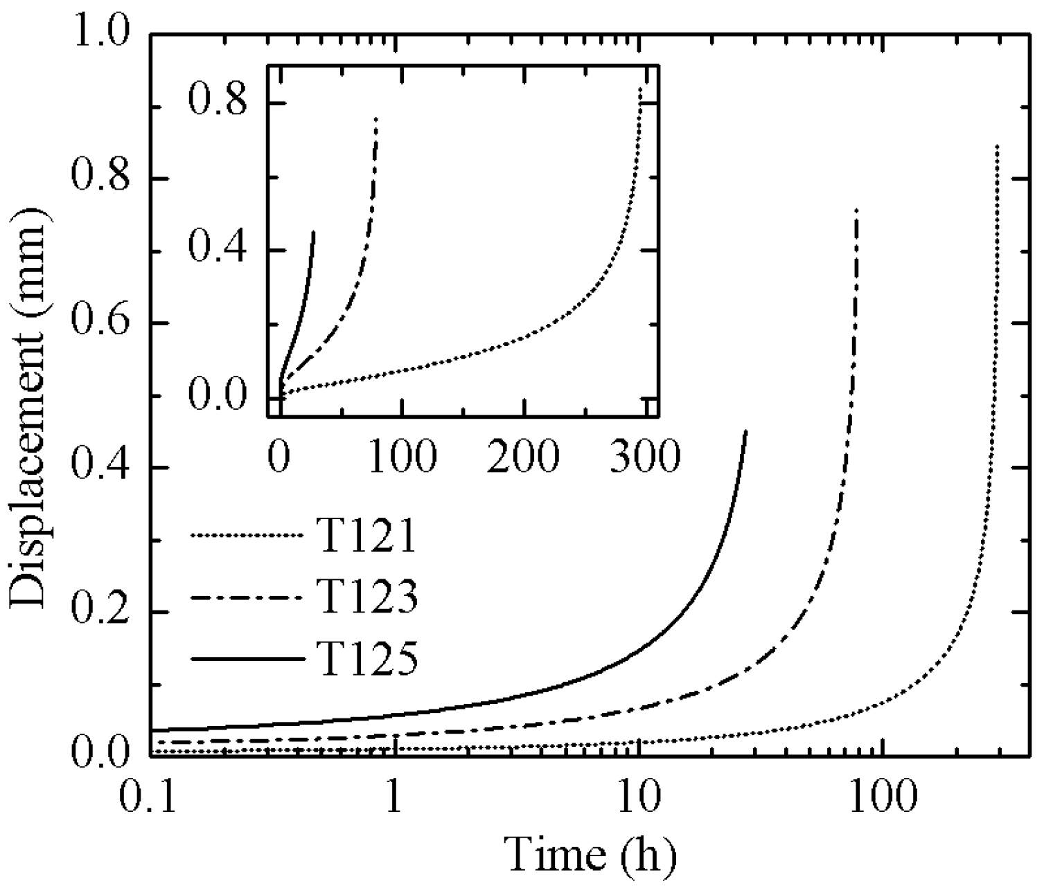
The initial ovality is introduced into the cylindrical shell in the creep buckling analysis. Some experimental cases in [11] are also used to validate the present FEM model. The cylinders of samples T121, T123, and T125 in [11] with the same applied pressure p but different initial geometrical imperfections are considered. The results are listed and compared in Table 2, and Figure 4 shows the displacement of the inner point at the minor axis of the middle cross-section of the shell (point q in Figure 3b). It can be seen that the creep deformation tends to further increase the initial ovality. The critical time of creep buckling is obtained by observing the time when the creep deformation varies rapidly with time. We notice that when the maximum stress reaches the yield stress, the creep deformation increases rapidly. A plastic hinge feature could occur, and the time step is considerably small for a convergent solution. It can be indicated that the critical time is significantly influenced by the initial ovality imperfections. The larger the imperfections, the shorter the critical time. The critical time results of the FEM model show some differences from those of the experiments. The results difference may come from the errors of the material models (including the creep model and the plastic hardening model), the shell element (it is defined in the bottom surface in Abaqus software in this present study), the geometrical imperfections, and the boundary difference between the experiment and FEM models. Nevertheless, we consider that this present FEM model can be further used to investigate the influence of the local defects.

3.2. Creep Buckling of Cylindrical Shell with Local Thinning Defects ( ξ = 0 )

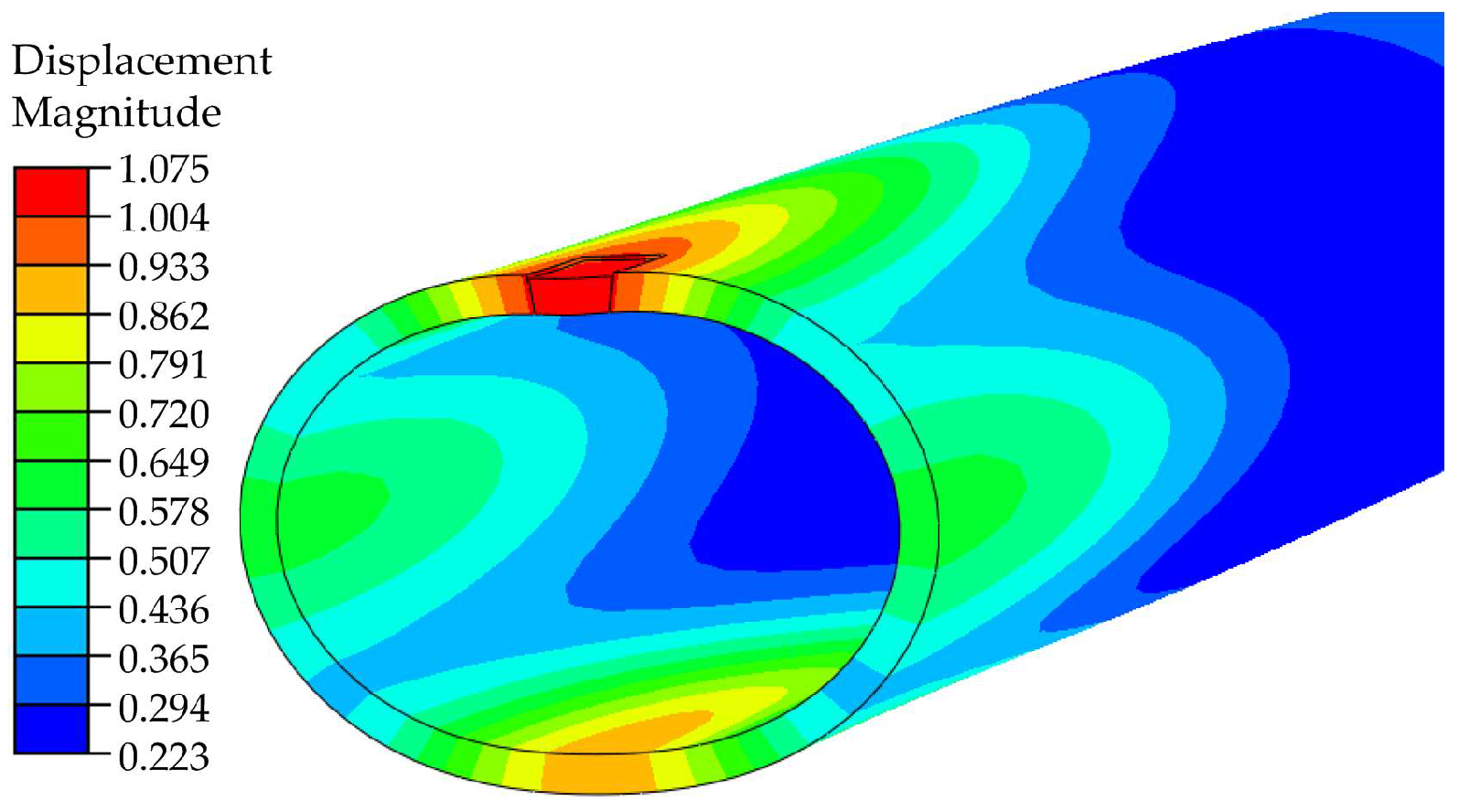
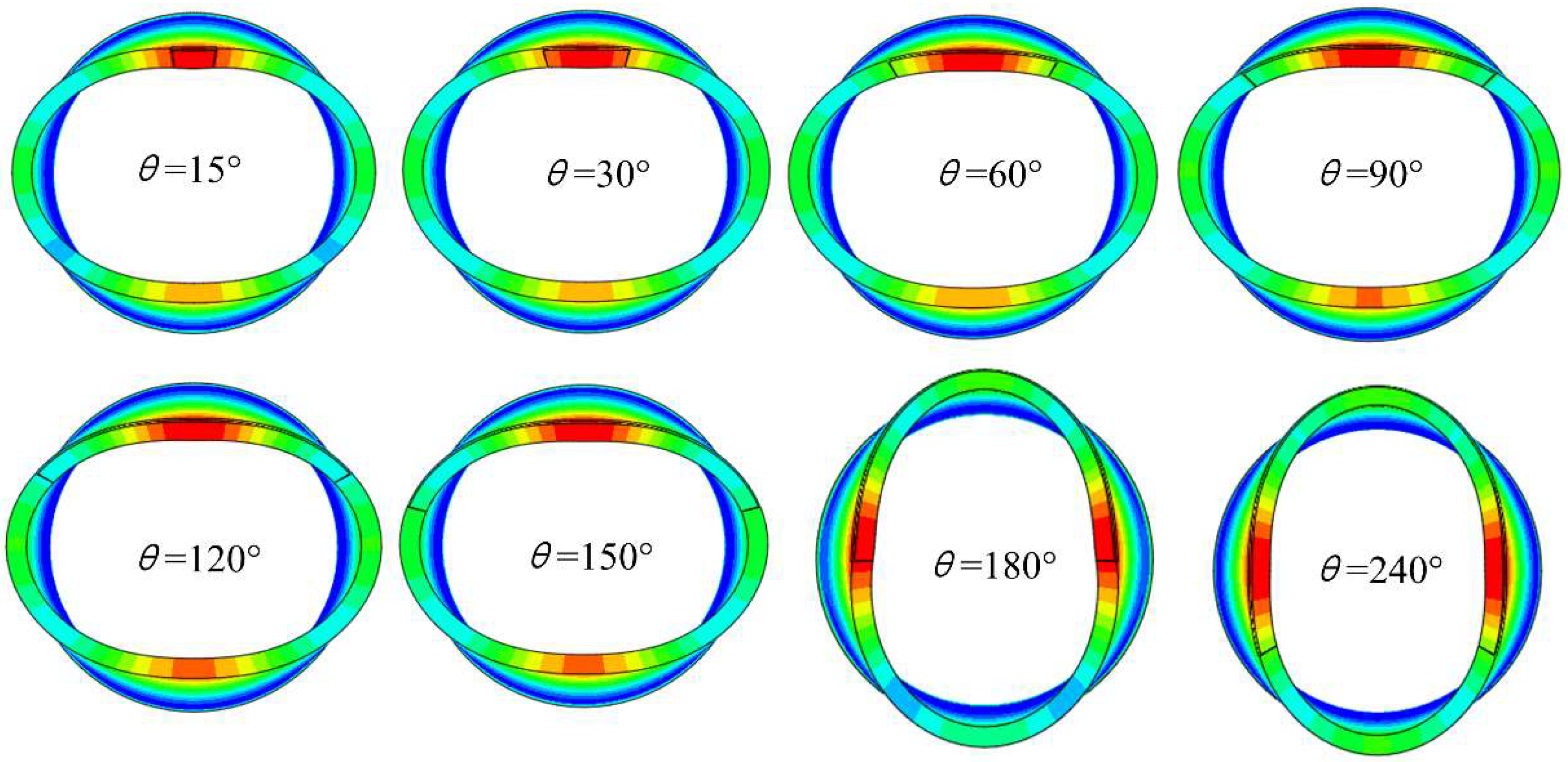
The creep deformation and buckling features of the cylindrical shell with local thinning defects but without initial ovality, i.e., ξ = 0 , is then investigated. Figure 5 shows the displacement of point q in Figure 2 along the Y-axis for d / t = 0.1 . The absolute values are taken for the displacement of θ = 15 ° ~ 150 ° as they are negative values along the negative direction of the Y-axis and show an almost opposite tendency to that of θ = 180 ° ~ 240 ° . The critical buckling time is considerably larger than that in Section 3.1 with the global imperfections. However, they seem to decrease with θ at first and then increase with θ , and finally decrease. It is reasonable that the critical buckling time is infinity if θ = 0 as there is no defect and the load is lower than the critical buckling pressure. The feature of the critical buckling time increasing with θ , maybe due to the dominant buckling mode, is changed, which will be further illustrated in the following. The collapse pressure in [28] also shows a similar feature. Figure 6 shows a typical creep buckling deformation configuration near the middle cross-section with θ = 15 ° and d / t = 0.1 . It indicates that the buckling mode of the middle cross-section almost coincides with the ovality configuration, although the deformation magnitude of the local thinning region is the greatest. Figure 7 and Figure 8 show the creep buckling modes of the cylindrical shell with different local defects, where the magnitude of the displacement is drawn in the graphs. All buckling modes almost show the ovality configuration, but the minor and major axes will switch with increasing of the defect width, i.e., c or θ , which is the reason that the displacement of θ = 180 ° ~ 240 ° shows an opposite tendency in Figure 5. It should be noticed that a pear-mode also appears if the defect thickness is considerably large; see d / t = 0.4 with θ = 150 ° ~ 180 ° in Figure 8. This feature also appears in the elastic buckling modes, as shown in [28], while the types of the creep buckling modes are not as many as those in the elastic buckling.
The critical creep buckling time for various defect parameters is listed in Table 3. It can be seen that the tendency of the critical buckling time with θ of each d / t is similar to that of d / t = 0.1 mentioned above. Moreover, the critical buckling time of creep buckling decreases significantly with deeper defects.

3.3. Creep Buckling of Cylindrical Shell with Initial Ovalities and Local Thinning Defects

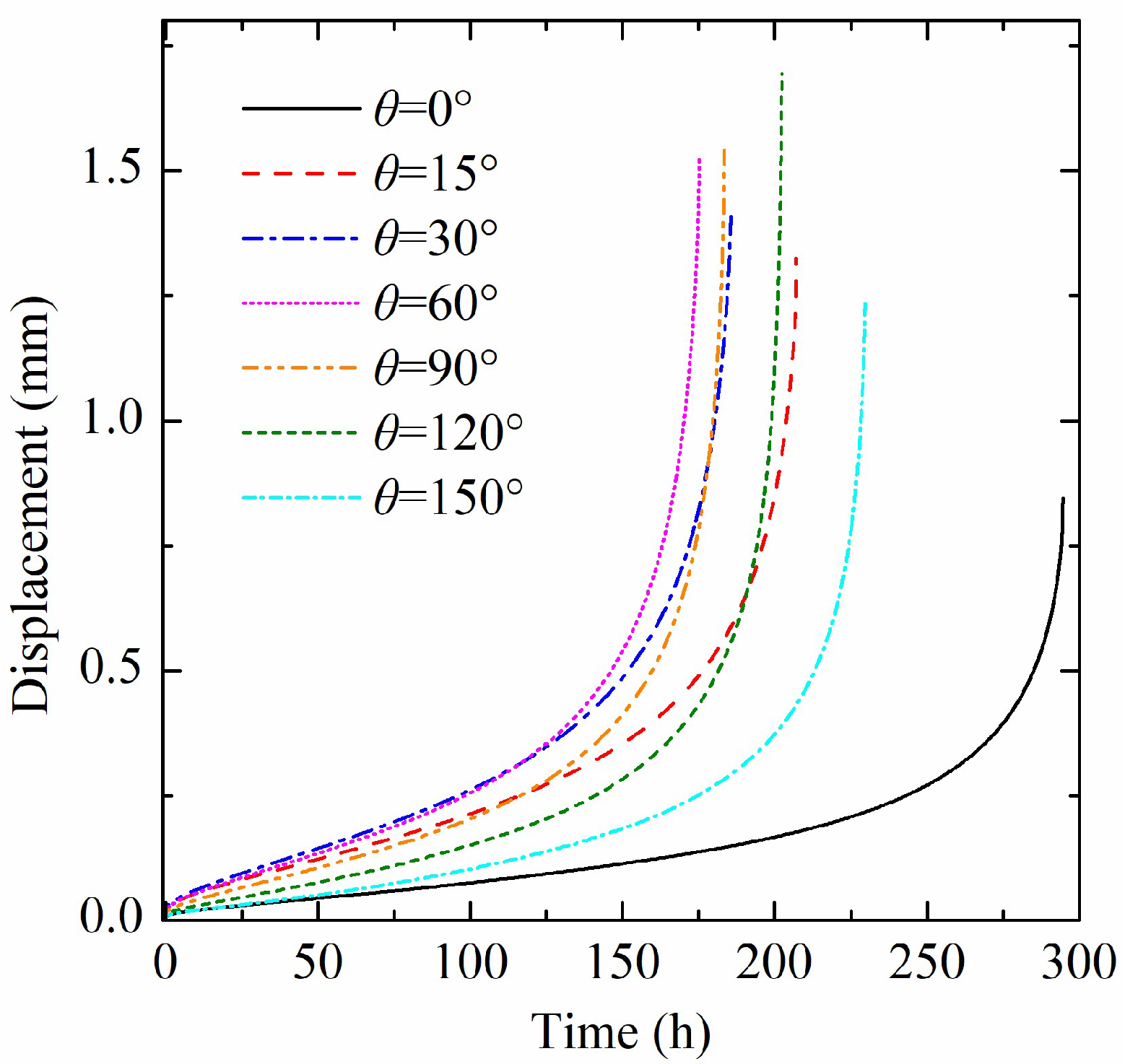
The combined influence of the global imperfections, i.e., the initial ovalities, and the local thinning defects on the creep buckling is finally investigated. Two initial ovalities of ξ = 0.0075 (case T121) and ξ = 0.11 (case T125) with d / t = 0.4 are focused. In this present study, we consider a special case where the local thinning defect is located at the minor axis of an oval shape. Figure 9 shows the absolute values of the creep displacement of point q along the Y-axis in case T121. We can also see that the deformation and the critical buckling time with θ shows a similar tendency to that in Section 3.2. Furthermore, the local thinning defects can significantly decrease the critical buckling time. Figure 10 shows the creep buckling modes results. The local thinning region also shows the greatest magnitude of deformation. It is indicated that the buckling modes are dominated by the ovality deformation in a large range of defect width, i.e., c or θ . Moreover, the pear-mode that has appeared in the case of ξ = 0 with θ = 150 ° does not occur in the present cases. Table 4 lists the critical creep buckling time for various initial ovalities with d / t = 0.4 . It shows that both the global imperfections and the local defects can considerably decrease the critical buckling time. Considering T121 as an example, the critical buckling time of the case θ = 15 ° is almost 30 % less than that of the case θ = 0 ° . Therefore, even if a small local defect appears, the critical buckling time could be shortened severely. The feature can also be revealed in Figure 11, where a comparison of the critical time for various parameters is provided.

4. Conclusions

The creep buckling behavior of a cylindrical shell subjected to external lateral pressure with local wall-thinning defects is preliminarily studied in this paper. An FEM model of the Zircaloy cylindrical shell is developed for creep buckling analysis, and its efficiency is validated by the experimental results in the literature. A sector-shaped local wall-thinning defect is introduced on the external surface of the cylindrical shell with three geometric parameters. The influences of the local defect parameters and the global imperfections, i.e., the initial ovality, especially their combinations, on the creep buckling behavior are investigated. Based on the creep buckling analysis, the results can be obtained as follows:
(1)
The buckling modes for the considered model are dominated by the ovality deformation in a large range of defect width, whether the global initial ovality imperfection appears or not. For the case without initial ovality, the minor and major axes of the ovality configuration in buckling modes will switch with increasing the defect width, and a pear-mode also appears if the defect thickness is considerably large.
(2)
In comparison to the defect width, the critical buckling time is more sensitive to the defect thickness and decreases significantly with the defect thickness. If the global imperfection occurs, the local thinning defects can reduce the critical buckling time more severely, and a 30% reduction was observed even with a small local defect, which could be a common situation in engineering practice.
Therefore, if some corrosion, erosion, or worn defects appear on the surface of the cylindrical shells serving in high-temperature environments with high pressure, it is necessary to perform a careful reevaluation of the serving life or safety. For the analysis of practical applications, more precise FEM models could be developed with experimental validations for accuracy. Moreover, after the present preliminary study, more combinations of the local defects and the initial oval shape, including different geometric and location parameters, can be investigated in further study.

Author Contributions

Conceptualization, Z.C. and J.Z.; methodology, Z.C. and H.W.; validation, Z.C.; formal analysis, Z.C., H.W., Y.P. and C.Z.; investigation, Z.C. and H.W.; data curation, Z.C.; writing—original draft preparation, Z.C. and J.Z.; writing—review and editing, Z.C., H.W., Y.P., C.Z., L.H. and J.Z.; supervision, L.H. and J.Z.; project administration, J.Z.; funding acquisition, J.Z. All authors have read and agreed to the published version of the manuscript.

Funding

This research was funded by the Guangdong Basic and Applied Basic Research Foundation, grant numbers 2024A1515030048 and 2022A1515011422.

Institutional Review Board Statement

Not applicable.

Informed Consent Statement

Not applicable.

Data Availability Statement

The data presented in this study are available on request from the corresponding author.

Conflicts of Interest

The authors declare no conflicts of interest.

References

  1. Zhao, C.; Xiong, Y.; Liu, Y.; Xue, J.; Xu, P. Creep buckling of long-term-serving super-heating pipes in boilers subjected to high temperature loading. Int. J. Press. Vessel. Pip. 2022, 200, 104822. [Google Scholar] [CrossRef]
  2. Aybar, H.S.; Ortego, P. A review of nuclear fuel performance codes. Prog. Nucl. Energy 2005, 46, 127–141. [Google Scholar] [CrossRef]
  3. Jo, B.; Okamoto, K.; Kasahara, N. Creep buckling of 304 stainless-steel tubes subjected to external pressure for nuclear power plant applications. Metals 2019, 9, 536. [Google Scholar] [CrossRef]
  4. IAEA. Quality and Reliability Aspects in Nuclear Power Reactor Fuel Engineering; International Atomic Energy Agency: Vienna, Austria, 2024. [Google Scholar]
  5. Zhang, M.; Luo, Y.; Lu, Y.; Zhu, Y.; Liu, X.; Li, J.; Miao, X. On the creep collapse of the cladding considering the irradiation growth effect. In Proceedings of the 2023 Water Reactor Fuel Performance Meeting, Singapore, 17–21 July 2024; pp. 16–19. [Google Scholar]
  6. Musa, A.E.S.; Al-Ainieh, M.M.K.; Al-Osta, M.A. Buckling of circular cylindrical shells under external pressures—A critical review. J. Constr. Steel Res. 2025, 228, 109439. [Google Scholar] [CrossRef]
  7. Cancemi, S.A.; Lo Frano, R. Preliminary analysis of long-term performance of a piping: Aging and creep effects. Materials 2021, 14, 1703. [Google Scholar] [CrossRef] [PubMed]
  8. Jawad, M.; Griffin, D. Design limits for buckling in the creep range. J. Press. Vessel. Technol. 2012, 134, 065001. [Google Scholar] [CrossRef]
  9. Miyazaki, N.; Hagihara, S. Creep buckling of shell structures. Mech. Eng. Rev. 2015, 2, 14-00522. [Google Scholar] [CrossRef]
  10. Sammari, A.; Jullien, J.F. Creep buckling of cylindrical shells under external lateral pressure. Thin-Walled Struct. 1995, 23, 255–269. [Google Scholar] [CrossRef]
  11. Combescure, A. Simplified prediction of the creep buckling of cylinders under external pressure. Part 2: Experimental verification. Eur. J. Mech.-A/Solids 1999, 18, 1045–1059. [Google Scholar] [CrossRef]
  12. Lo Frano, R.; Forasassi, G. Experimental evidence of imperfection influence on the buckling of thin cylindrical shell under uniform external pressure. Nucl. Eng. Des. 2009, 239, 193–200. [Google Scholar] [CrossRef]
  13. Koundy, V.; Forgeron, T.; Hivroz, J. Creep buckling of ovalized tubes under external pressure. J. Press. Vessel. Technol. 1996, 118, 460–463. [Google Scholar] [CrossRef]
  14. Combescure, A. Simplified prediction of creep buckling of cylinders under external pressure. Part 1: Finite element validation. Eur. J. Mech.-A/Solids 1998, 17, 1021–1036. [Google Scholar] [CrossRef]
  15. Combescure, A.; Jullien, J.-F. Creep buckling of cylinders under uniform external pressure: Finite element simulation of buckling tests. Int. J. Solids Struct. 2017, 124, 14–25. [Google Scholar] [CrossRef]
  16. Schmidt, H. Stability of steel shell structures: General Report. J. Constr. Steel Res. 2000, 55, 159–181. [Google Scholar] [CrossRef]
  17. Schneider, W.; Brede, A. Consistent equivalent geometric imperfections for the numerical buckling strength verification of cylindrical shells under uniform external pressure. Thin-Walled Struct. 2005, 43, 175–188. [Google Scholar] [CrossRef]
  18. Rathinam, N.; Prabu, B. Static buckling analysis of thin cylindrical shell with centrally located dent under uniform lateral pressure. Int. J. Steel Struct. 2013, 13, 509–518. [Google Scholar] [CrossRef]
  19. Rathinam, N.; Prabu, B. Numerical study on influence of dent parameters on critical buckling pressure of thin cylindrical shell subjected to uniform lateral pressure. Thin-Walled Struct. 2015, 88, 1–15. [Google Scholar] [CrossRef]
  20. Du, X.; Zhang, J.; Liu, Y. Plastic failure analysis of defective pipes with creep damage under multi-loading systems. Int. J. Mech. Sci. 2017, 128–129, 428–444. [Google Scholar] [CrossRef]
  21. Du, X.; Liu, Y.; Zhang, J. High temperature limit analysis of pressure vessels and piping with local wall-thinning. In Advances in Direct Methods for Materials and Structures; Barrera, O., Cocks, A., Ponter, A., Eds.; Springer International Publishing: Cham, Switzerland, 2018; pp. 199–217. [Google Scholar]
  22. Rathinam, N. Investigations on the Effect of Geometrical Imperfections on the Buckling of Thin Cylindrical Shells Under Uniform Lateral Pressure. Ph.D. Thesis, Pondicherry University, Puducherry, India, 2016. [Google Scholar]
  23. Hussain, H.; Gao, X.; Shi, A. A finite element study on compressive resistance degradation of square and circular steel braces under axial cyclic loading. Appl. Sci. 2021, 11, 6094. [Google Scholar] [CrossRef]
  24. Gong, S.; Zhou, L.; Wang, X.; Yuan, L.; Liu, C. On the collapse of thick-walled pipes with corrosion defects under external pressure. Mar. Struct. 2021, 76, 102925. [Google Scholar] [CrossRef]
  25. Musa, A.E.S.; Al-Shugaa, M.A.; Al-Gahtani, H.J. The buckling strength of axially compressed thin circular cylindrical shells subjected to dent imperfection. Arab. J. Sci. Eng. 2023, 48, 5481–5492. [Google Scholar] [CrossRef]
  26. Zhou, S.; Zhao, Z.; Lao, Z.; Gao, H. Buckling capacity of spherical shells with local thickness reduction under radial ring load. Int. J. Press. Vessel. Pip. 2025, 214, 105441. [Google Scholar] [CrossRef]
  27. Fatt, M.S.H. Elastic-plastic collapse of non-uniform cylindrical shells subjected to uniform external pressure. Thin-Walled Struct. 1999, 35, 117–137. [Google Scholar] [CrossRef]
  28. Netto, T.A.; Ferraz, U.S.; Botto, A. On the effect of corrosion defects on the collapse pressure of pipelines. Int. J. Solids Struct. 2007, 44, 7597–7614. [Google Scholar] [CrossRef]
  29. Sakakibara, N.; Kyriakides, S.; Corona, E. Collapse of partially corroded or worn pipe under external pressure. Int. J. Mech. Sci. 2008, 50, 1586–1597. [Google Scholar] [CrossRef]
  30. Netto, T.A. On the effect of narrow and long corrosion defects on the collapse pressure of pipelines. Appl. Ocean. Res. 2009, 31, 75–81. [Google Scholar] [CrossRef]
  31. Moreira Junior, N.M.; Carrasquila, A.A.; Figueiredo, A.; da Fonseca, C.E. Worn pipes collapse strength: Experimental and numerical study. J. Pet. Sci. Eng. 2015, 133, 328–334. [Google Scholar] [CrossRef]
  32. Yan, S.-T.; Shen, X.-L.; Jin, Z.-J.; Ye, H. On elastic-plastic collapse of subsea pipelines under external hydrostatic pressure and denting force. Appl. Ocean. Res. 2016, 58, 305–321. [Google Scholar] [CrossRef]
  33. Fan, Z.; Yu, J.; Sun, Z.; Wang, H. Effect of axial length parameters of ovality on the collapse pressure of offshore pipelines. Thin-Walled Struct. 2017, 116, 19–25. [Google Scholar] [CrossRef]
  34. Wu, H.; Zhao, H.; Li, X.; Feng, X. A semi-analytical approach to elastic–plastic buckling analysis of pipes with asymmetric local wall thinning. Thin-Walled Struct. 2021, 162, 107615. [Google Scholar] [CrossRef]
  35. Chen, Y.; Dong, S.; Zang, Z.; Gao, M.; Zhang, H.; Ao, C.; Liu, H.; Ma, S.; Liu, H. Collapse failure and capacity of subsea pipelines with complex corrosion defects. Eng. Fail. Anal. 2021, 123, 105266. [Google Scholar] [CrossRef]
  36. Chen, B.-Q.; Zhang, X.; Guedes Soares, C. The effect of general and localized corrosions on the collapse pressure of subsea pipelines. Ocean. Eng. 2022, 247, 110719. [Google Scholar] [CrossRef]
  37. Zhou, L.; Lin, Y.; Gong, S. On the collapse of thick-walled steel pipes under coupling initial geometric imperfection and corrosion defect. Ships Offshore Struct. 2023, 18, 325–337. [Google Scholar] [CrossRef]
  38. Tian, H.; Guan, F.; Wan, F.; Yang, Y.; Liu, W. The effect of corrosion defects on the collapse pressure of submarine pipelines. Ocean. Eng. 2024, 310, 118647. [Google Scholar] [CrossRef]
  39. Zhou, L.; Gong, S.; Yuan, L.; Wang, X.; Huang, J. Theoretical analysis of the collapse behaviour of subsea pipelines with corrosion defects under external pressure. Ocean. Eng. 2024, 307, 118069. [Google Scholar] [CrossRef]
  40. Park, J.-Y.; Choi, B.-K.; Yoo, S.J.; Jeong, Y.H. Corrosion behavior and oxide properties of Zr–1.1wt% Nb–0.05wt% Cu alloy. J. Nucl. Mater. 2006, 359, 59–68. [Google Scholar] [CrossRef]
  41. Kim, H.-K.; Lee, Y.-H.; Lee, K.-H. On the geometry of the fuel rod supports concerning a fretting wear failure. Nucl. Eng. Des. 2008, 238, 3321–3330. [Google Scholar] [CrossRef]
  42. Kim, K.-T.; Suh, J.-M. Impact of nuclear fuel assembly design on grid-to-rod fretting wear. J. Nucl. Sci. Technol. 2009, 46, 149–157. [Google Scholar] [CrossRef]
  43. Khattak, M.; Omran, A.A.B.; Kazi, S.; Khan, M.; Ali, H.M.; Tariq, S.L.; Akram, M.A. A review of failure modes of nuclear fuel cladding. J. Eng. Sci. Technol. 2019, 14, 1520–1541. [Google Scholar]
Figure 1. The initial ovality imperfection.
Applsci 15 10005 g001
Figure 2. Description of the local wall-thinning defect.
Applsci 15 10005 g002
Figure 3. Elastic buckling analysis results: (a) the mesh convergence study; (b) the first-order buckling mode.
Applsci 15 10005 g003
Figure 4. The inward displacement of point q with different initial ovality (middle cross-section).
Applsci 15 10005 g004
Figure 5. The creep deformation with time for d / t = 0.1 .
Applsci 15 10005 g005
Figure 6. Typical creep deformation of the middle cross-section ( ξ = 0 θ = 15 °   a n d   d / t = 0.1 ) .
Applsci 15 10005 g006
Figure 7. Creep buckling modes for ξ = 0   a n d   d / t = 0.1 .
Applsci 15 10005 g007
Figure 8. Creep buckling modes for ξ = 0   a n d   d / t = 0.4 .
Applsci 15 10005 g008
Figure 9. The creep deformation for case T121 with d / t = 0.4 .
Applsci 15 10005 g009
Figure 10. Creep buckling modes for various initial ovalities with d / t = 0.4 .
Applsci 15 10005 g010
Figure 11. Comparison of the critical buckling time for various parameters.
Applsci 15 10005 g011
Table 1. Geometric parameter selection for the imperfections.
Geometric ParameterValue
ξ 0, 0.0075, 0.11
d / t 0.1, 0.2, 0.4
θ 15°, 30°, 60°, 90°, 120°, 150°, 180°, 240°
Table 2. The critical buckling time of cylinders.
Cylinderξ P / P E Critical Buckling Time (h)
ExperimentFEM
T1210.00750.258220294.6
T1230.050.2584878.0
T1250.110.2582031.0
Table 3. The critical creep buckling time for various local thinning defects.
d/tCritical Time (h)
θ = 15°θ = 30°θ = 60°θ = 90°θ = 120°θ = 150°θ = 180°θ = 240°
0.11046.5848.42681.92675.39758.23912.261154.37626.05
0.2691.91552.79461.20466.49540.24766.79642.23379.52
0.4360.87295.27267.41297.78420.45424.31225.10170.50
Table 4. The critical creep buckling time for various initial ovalities with d / t = 0.4 .
CylinderCritical Buckling Time (h)
θ = 0°θ = 15°θ = 30°θ = 60°θ = 90°θ = 120°θ = 150°
T121294.55207.11185.58175.18183.31202.24229.72
T12530.9625.6424.7123.9523.9223.0620.48
Disclaimer/Publisher’s Note: The statements, opinions and data contained in all publications are solely those of the individual author(s) and contributor(s) and not of MDPI and/or the editor(s). MDPI and/or the editor(s) disclaim responsibility for any injury to people or property resulting from any ideas, methods, instructions or products referred to in the content.