Article

Experimental Investigation of Wetting Materials for Indirect Evaporative Cooling Applications

1
School of Engineering, University of Tasmania, Hobart, TAS 7001, Australia
2
Sotera Fire Engineering, 21 Sunshine Parade, Gold Coast, QLD 4220, Australia
3
School of Mechanical Engineering, The University of Adelaide, Adelaide, SA 5005, Australia
4
Biology and Environmental Science and Engineering, King Abdullah University of Science and Technology, Thuwal 23955-6900, Saudi Arabia
*
Author to whom correspondence should be addressed.
Appl. Sci. 2025, 15(17), 9818; https://doi.org/10.3390/app15179818
Submission received: 8 July 2025 / Revised: 31 August 2025 / Accepted: 5 September 2025 / Published: 7 September 2025
(This article belongs to the Section Applied Thermal Engineering)

Abstract

The indirect evaporative cooling system, which exploits the water evaporation process to generate cooling loads without introducing additional moisture, has been recognised as a viable alternative to conventional air-conditioning systems. This acknowledgment is due to its attributes of energy efficiency and environmental friendliness. The meticulous selection of wetting materials for an indirect evaporative cooler is of paramount importance as it significantly influences the heat and mass transfer performance of the system. Therefore, this paper experimentally examined a novel material produced by laser-resurfaced technology, and this material was compared with four other distinct materials (kraft paper, cotton fibre, polyester fibre, and polypropylene + nylon fibre) while considering the wicking ability, water-holding capacity, and thermal response performance. The results revealed that the fabric materials, specifically cotton fibre and polyester fibre, exhibited outstanding water-wicking ability, with a vertical wicking distance exceeding 16 cm. Cotton fibre also demonstrated an exceptional water-holding ability, registering a value of 0.0754 g/cm2. In terms of thermal response performance, polypropylene + nylon fibre and the laser-resurfaced polymer achieved stable conditions within one minute, which could be attributed to the absence of a mechanical support plate and adhesive layer. All five materials attained stability after 4.2 min. Cotton and polyester fibres exhibited advantages in the duration of the evaporation process, maintaining stable conditions for 24 and 90 min, respectively. Based on the experimental results, appropriate water-spray strategies are proposed for each material.

1. Introduction

Evaporative cooling technology (ECT) utilises the latent heat of water evaporation to generate cooling effects, thus representing a promising alternative to traditional air-conditioning systems in terms of energy saving [1,2]. According to the working principle of ECT, the following two main groups can be categorised: direct evaporative cooling (DEC) and indirect evaporative cooling (IEC) [3]. DEC entails the direct contact of incoming air with water, resulting in heat dissipation through the evaporation phenomenon concomitant with an increase in air humidity [4]. However, the heightened humidity levels can potentially cause uncomfortable thermal conditions and, in more severe instances, may give rise to health-related issues for individuals inhabiting built structures [5]. This limitation can be mitigated by employing IEC, which separates the air supply from the working air, thereby enabling the cooling of air without a concurrent augmentation of its humidity [6]. Due to this feature, IEC has recently garnered significant adoption within evaporative air-conditioning systems.
In order to enhance the cooling performance of IEC, numerous research studies have been conducted. In addition to optimising the IEC structure to advance the heat and mass transfer rates [7,8,9,10,11], substantial efforts have also been made to investigate the evaporation medium or wetting media within the wet channels. This is because the properties of the heat and mass transfer medium, including its capacity for water-wicking and evaporation, can directly influence the cooling efficiency and performance of IEC systems [12].
Kraft paper is one of the most commonly used wetting materials for ECT due to its hydrophilic nature and low thickness [13]. Khalid et al. [13] utilised 0.3 mm thick kraft paper as the wet channel material within an IEC system. Their findings indicated that the wet-bulb and dew point effectiveness exhibited values ranging from 104 to 120% and 67 to 87%, respectively. However, it should be noted that kraft paper’s wicking performance and diffusion rate do not excel when compared with other textile fibre fabrics and fibre distortion may become apparent following the drying process [14,15]. Consequently, researchers have embarked on investigating the viability of substituting textile fibres with kraft paper as the wet channel material for IEC. Riangvilaikul and Kumar [16] presented an experimental investigation in which cotton fibre was selected as the wet channel material. Their research findings revealed that the maintenance of dew point and wet-bulb effectiveness at approximately 76% and 102%, respectively, was achievable throughout a typical summer day. Xu et al. [12] conducted an experimental study involving six different fabric materials for use in IEC applications and subsequently compared their performance with kraft paper. The results indicated that the majority of the fabrics showed notably enhanced characteristics compared with kraft paper, with the wicking ability demonstrating an increase of 171 to 182%, diffusivity showing an enhancement of 298 to 396%, and evaporation registering an improvement of 77 to 93%. Similarly, Abada et al. [15] performed an experimental study to identify a prospective substitute material for kraft paper, which is conventionally employed as a wet substrate in ECT. They observed that certain fabrics had a water absorption capacity exceeding that of kraft paper by a range of 160 to 355%. In addition, fabrics with tight straight-weave fibres and polypropylene geotextile felt were recommended for their potential to enhance the efficiency of IEC. Xu et al. [17] applied Coolmax, a specially designed polyester fibre characterised by remarkable attributes related to its water diffusion, absorption, and evaporation capabilities, as the wet channel material for an IEC system. The results revealed that the engineered prototype yielded a Coefficient of Performance (COP) of 52.5 and wet-bulb effectiveness of 114%. Chen et al. [18] proposed a novel visualised study that integrated digital image processing and fluorescence display technologies to scrutinise both the wetting ratio and thermal performance of a textile fibre composed of 30% polyester and 70% rayon. The results demonstrated a noteworthy enhancement in moisture dissipation capacity with the utilisation of fibre-coated IEC as the wetting ratio could attain 100% within a mere 30 s timespan.
Given the inherently hydrophilic and pliable characteristics of textile fibres, it is imperative to incorporate a surface with good mechanical strength to support the fibre and form the air channel wall, typically achieved through the utilisation of metal plates such as copper, aluminium, and their respective alloys [19,20]. Yang et al. [20] conducted a comprehensive review of the recent research advancements in the field of IEC and noted the extensive adoption of aluminium plates in IEC applications owing to their hydrophilic properties and high thermal conductivity. However, combining metal plates and fibres also engenders certain drawbacks, such as the overall system’s weight augmentation and heightened susceptibility to rust [19]. In this case, several research investigations have been undertaken to obviate the requirement for metal plates. Jia et al. [21] developed a novel IEC system using electrostatic flocking technology wherein nylon fibres were uniformly coated onto a polystyrene board. They concluded that the dew point effectiveness of the designed IEC system could reach a level of 78.6% while enabling the production of an equivalent cooling load with reduced dimensions and a decreased weight profile. Lv et al. [14] exploited a high-performance fibrous membrane consisting of polypropylene and nylon as the wetting medium for IEC. Their experimental investigation revealed that the porous fibrous membrane exhibited superior performance compared with the traditional material, demonstrating significant promise for potential applications within IEC. Chen et al. [22] employed a plant-fibre–polymer composite material as the wetting material in the context of IEC applications. In this configuration, the polymer layer is oriented towards the dry channel, owing to its non-permeable properties, while the plant fibre layer, distinguished by its good water-dispersing capabilities, is oriented towards the wet channel. Fang et al. [23] employed a femtosecond laser processing technique to fabricate a wicking material based on the nylon 6 polymer. Their study highlighted the outstanding capillary characteristics exhibited by the resulting material, suggesting its potential utility in the context of IEC.
Based on an extensive literature review, it can easily be identified that the optimisation of cooling performance in IEC can effectively be achieved by enhancing wetting conditions within the wet channels and reducing thermal resistance between the wet and dry channels. The effective realisation of these objectives is contingent upon carefully selecting appropriate wetting materials. Additionally, conventional wetting materials typically require attachment to a hydrophobic place to provide mechanical support. This composite arrangement, however, increases the overall thickness of the channel plate and impedes heat transfer. In contrast, laser-resurfacing technology enables the direct creation of hydrophilic surfaces on hydrophobic plates. This is accomplished through laser ablation, which generates microgrooves and nano-scale roughness on the material surface, thereby increasing the effective surface area and introducing capillary pathways for water-spreading. As a result, the need for additional layers is eliminated and the thermal performance is further enhanced. Despite the potential advantages of laser-resurfacing technology, its application remains at an early stage, with no systematic studies comparing its efficacy with a range of conventional wetting materials—encompassing natural fibre, composite fibre, and synthetic fibre—while considering the influence of the supporting plate. Furthermore, existing research primarily directs its attention towards the evaluation of the water-wicking and evaporation characteristics of these materials, often neglecting their thermal performance, particularly in relation to the thickness of the support plate. To address these gaps, this study presents an experimental investigation comparing the performance of a laser-resurfaced wicking material with other four distinct wetting media in terms of their moisture-wicking capabilities, evaporation rate, and thermal responses. Based on the testing results, proper water-spray strategies are recommended for each material. This investigation yields valuable insights, informing the selection of wetting materials for IEC applications.

2. Characteristics of the Materials

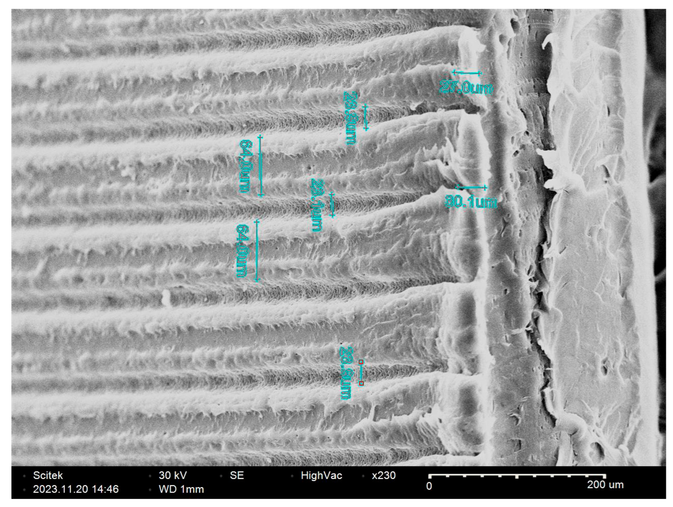
The present study investigates the following five distinct wetting materials: kraft paper, denoted as Sample A; cotton fibre, designated as Sample B; polyester fibre, identified as Sample C; a composite material consisting of polypropylene and nylon fibre achieved through flocking, denominated as Sample D; and a laser-resurfaced polymer sheet, referenced as Sample E. Among these, Samples A to D represent conventional wetting materials that have been widely studied or applied in IEC applications, whereas Sample E introduces a novel approach. These materials are depicted in Figure 1, and their respective characteristics and properties are detailed in Table 1. The scanning electron microscope (SEM) images of Sample E are provided in Figure 2. Notably, the images reveal the creation of numerous microgrooves through laser-cutting, endowing the material with the capacity to retain water. It is also worth noting that Samples A, B, and C should be attached to a supporting plate to enhance the overall mechanical robustness. In contrast, Samples D and E inherently possess the capacity to engender both dry and wet channels independently, obviating the need for supplementary structural reinforcement.

3. Experimental Methodology

In order to assess and compare the efficacy of diverse wetting materials, the following parameters should be encompassed within the evaluation framework: wicking capacity, water retention capability, evaporation rate, and thermal response analysis. The technical specifications of the laboratory equipment utilised are delineated in Table 2.

3.1. Wicking Capacity Test

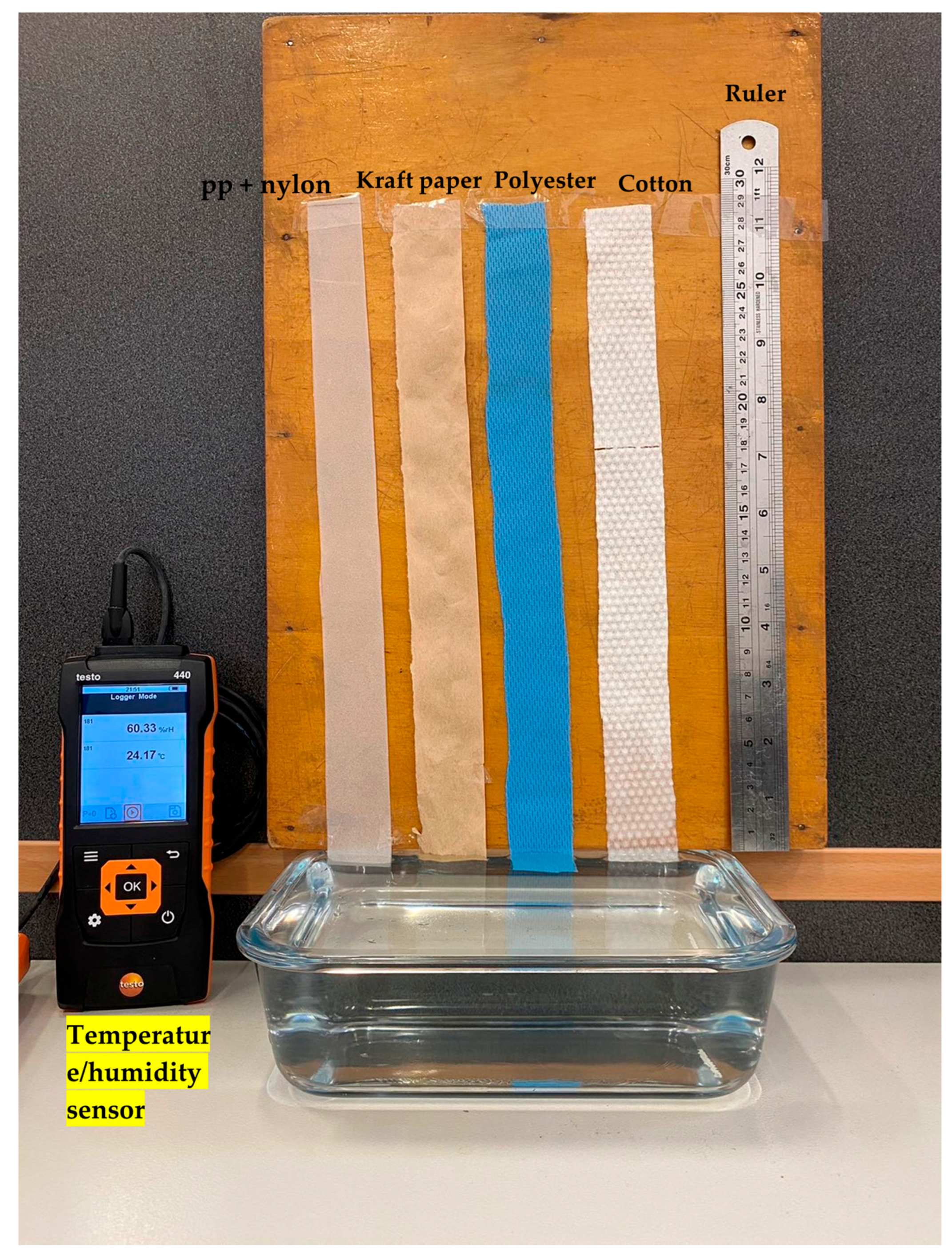
The evaluation of wicking performance for these materials entailed the measurement of wicking height, employing the experimental setup depicted in Figure 3. Preceding the initiation of the assessment, the materials were tailored into strips with dimensions of 35 cm × 3 cm. These strips were subsequently affixed to a wooden board, and their ends were immersed in water. Adjacent to the strips, a steel ruler was attached to ascertain and record the wicking height. Moreover, the testing conditions, including the temperature and relative humidity ratio, were monitored using a data logger. The wicking height of the materials was ascertained after a 60 min test under ambient conditions. In an effort to minimise potential experimental discrepancies, the experiments were iterated three times and the resultant data was presented as an average. It is noteworthy that, as illustrated in Figure 3, Sample E was absent from the test. This was attributed to the preliminary test results, which indicated that the wicking ability of this particular material was notably less discernible than the other samples.

3.2. Water-Holding Capacity

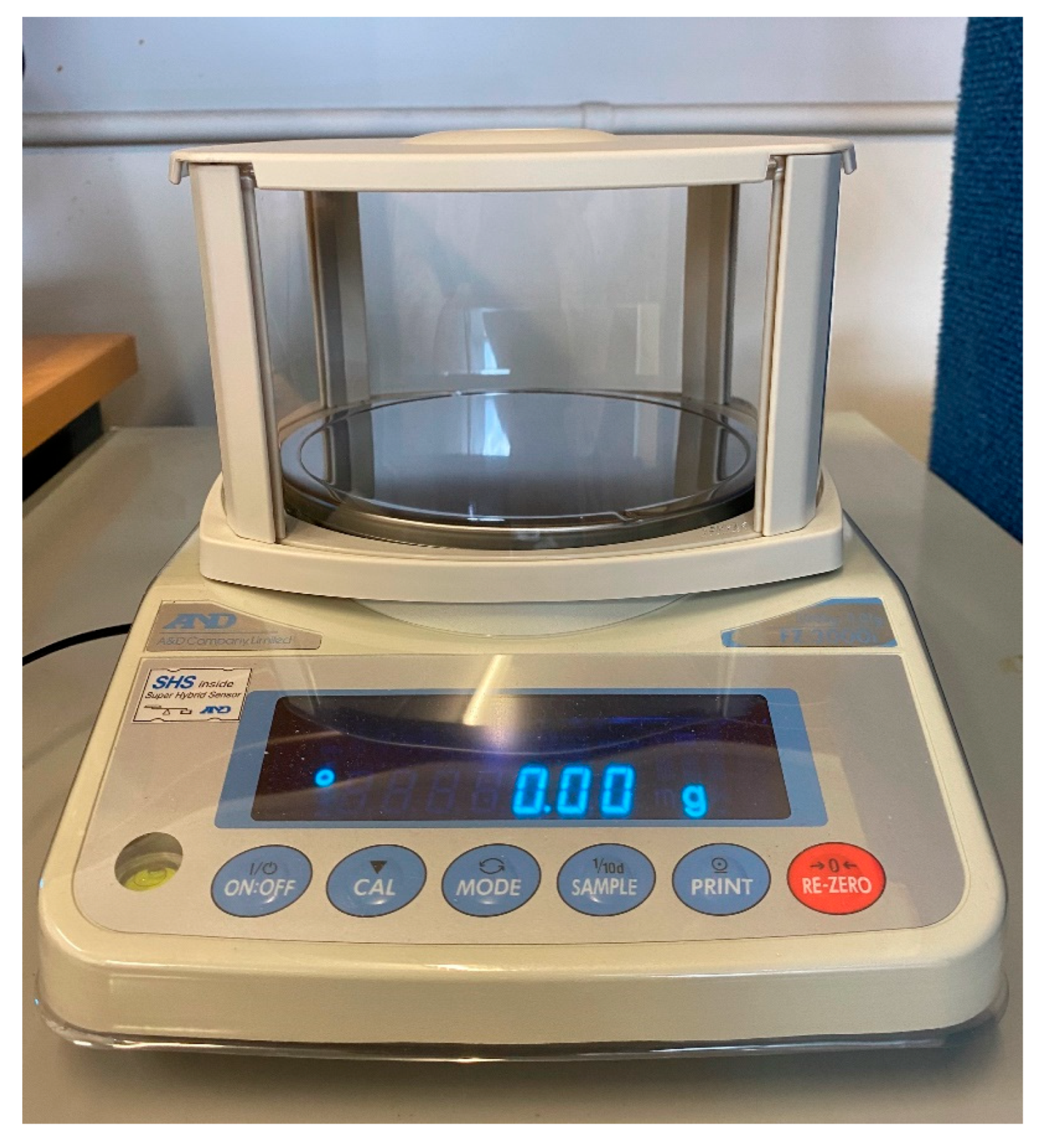
The water-holding capacity of a material includes both water retention and evaporation abilities. Initially, the sample materials were tailored to 10 cm × 10 cm strips. Subsequently, a high-precision scale (Figure 4) with an accuracy of 0.01 g was employed to measure the initial weight of each material. Following this, the samples underwent a thorough wetting process by immersion in water for 5 min, after which their weights were re-measured. The water retention rate is quantified by the ratio of the weight differential between the material’s dry and wet states to the material’s surface area, as expressed in Equation (1). Then, to evaluate the evaporation rate of the materials, the sample was positioned on the scale at room temperature until complete desiccation, during which the time and weight variations were meticulously recorded. The inclination of the trendline constituted the average evaporation rate for each material, as depicted in Equation (2).
S w h c = m A
Here, S w h c represents the water-holding capacity (g/cm2), m is the weight difference (g), and A denotes the surface area (cm2).
E = m A t
Here, E is the evaporation rate (g/(cm2·min)) and t implies the time interval (min).

3.3. Thermal Response Analysis

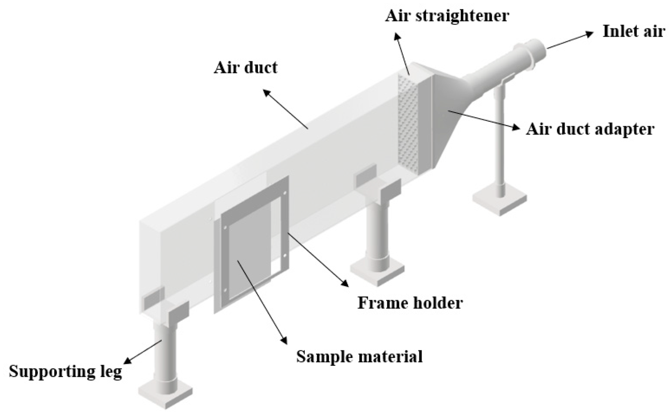
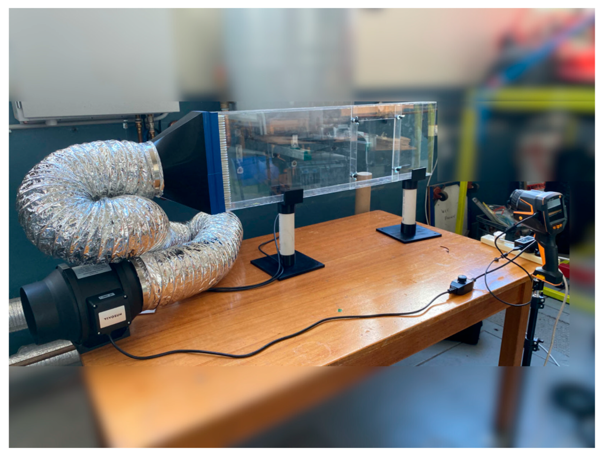
A dedicated testing apparatus was conceptualised and constructed to evaluate the thermal response characteristics of the various materials. The conceptual design and visual representation of the experimental prototype are delineated in Figure 5 and Figure 6, respectively. The inlet air, propelled by a fan blower, traverses through an air duct characterised by cross-sectional dimensions of 80 mm × 300 mm, facilitated by an air duct adapter. A structural element with a honeycomb configuration, denoted as the air straightener, is positioned at the starting point of the air duct to promote laminar airflow within the duct. In the present investigation, a square aperture was incised into the lateral surface of the air duct to facilitate the placement of the sample materials, which underwent thorough wetting. Then, a frame holder was employed to secure the materials in position, and a thermal imager was used to observe and record the temperature variations along the materials’ back surface. It should be noted that, in the case of certain pliable textile fibres, the augmentation of overall mechanical strength necessitates the incorporation of a metallic sheet. In this work, aluminium plates were chosen to serve this supportive function, and they were affixed to the textile using a marine-grade adhesive, Sikaflex-291, known for its efficacy in wet conditions. Furthermore, three distinct plate thicknesses (0.3 mm, 0.5 mm, and 1 mm) were chosen to systematically investigate the impact of plate thickness on the overall thermal response performance.

4. Results and Discussion

4.1. Wicking Height

Figure 7 illustrates the outcomes of the wicking height assessments conducted on the various sample materials. Sample B demonstrates superior wicking performance characterised by a rapid wicking rate, achieving 16.3 cm within a span of 5 min and attaining a maximum wicking distance of 23.6 cm. Sample C exhibits the second-highest wicking performance among the tested materials, registering a peak wicking distance of 16 cm. In contrast, the wicking performance of Sample D, while not reaching the level of cloth fabrics, is still noteworthy, reaching a maximum wicking height of 6.5 cm. Comparatively, the traditional material represented by Sample A displays a considerably low wicking height of 2.4 cm. It is noteworthy that the capillary phenomenon is absent in Sample E. Nevertheless, owing to the microgrooves engendered by laser treatment, the sample material could retain some water and evinced advantageous features in subsequent evaporation and thermal response tests, which are discussed in the following sections.

4.2. Water Retention Capacity

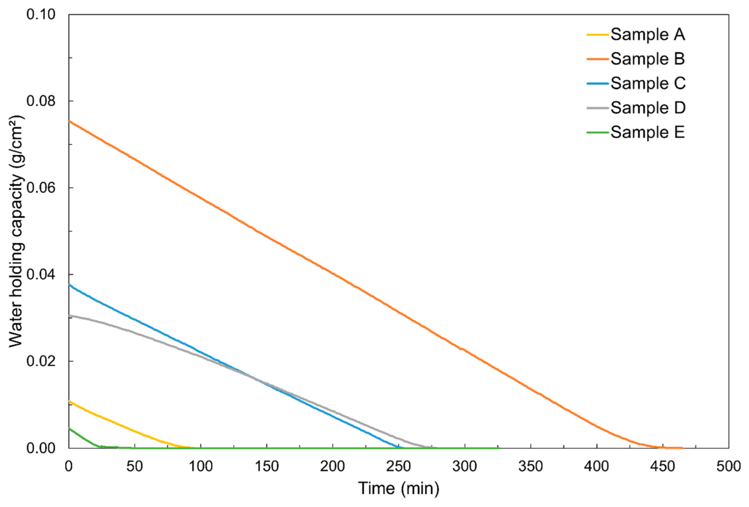
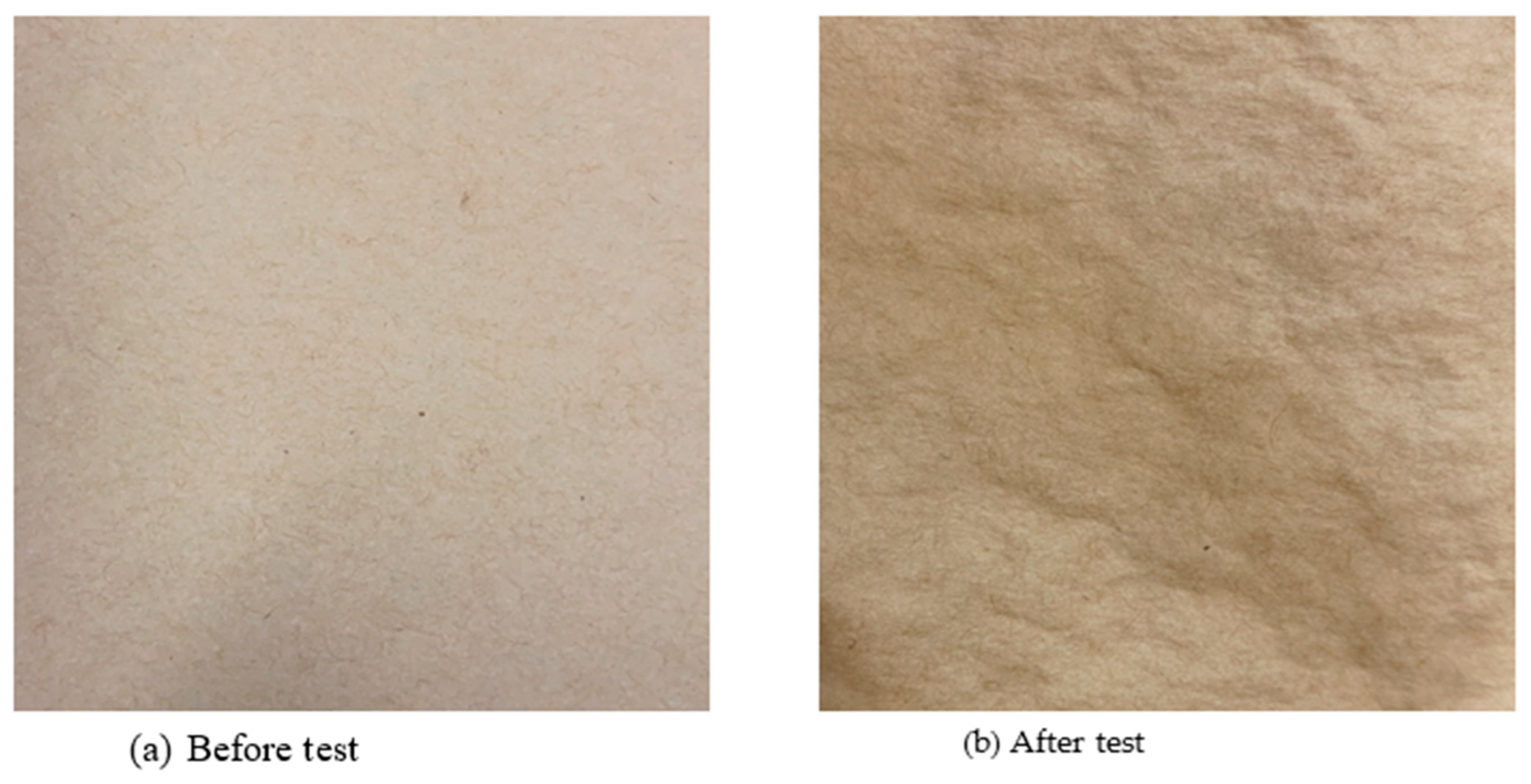
Figure 8 presents the water retention capacity of the five examined materials. Sample B demonstrates the highest water-holding ability, attaining a value of 0.0754 g/cm2. Samples C and D exhibit comparable water-holding capacities, recording values of 0.0375 g/cm2 and 0.0306 g/cm2, respectively. Conversely, Samples A and E manifest the least effective water retention performance, displaying values of 0.0109 g/cm2 and 0.0043 g/cm2, respectively. The parameter associated with evaporation time serves as an initial metric for optimising the temporal intervals of water-spraying strategies in IEC, aiming to conserve both energy and water resources. Figure 8 shows that approximately 450 min is required for the transition of Sample B from a wet state to complete dryness, constituting the longest duration among the five materials. In contrast, Samples A and E exhibit markedly shorter durations, requiring merely 95 min and 27 min, respectively. For Samples C and D, the transition process takes between 250 and 275 min. Notably, the linear trendlines characterising the relationship between the water-holding capacity and time for all materials indicate constant evaporation rates. The calculated evaporation rates for Samples A to E, derived from Equation (2), are as follows: 0.0001 g/(cm2·min), 0.0002 g/(cm2·min), 0.0001 g/(cm2·min), 0.0001 g/(cm2·min), and 0.0002 g/(cm2·min). This observation underscores that Samples B and E exhibit superior evaporation rates. Following the experimental trials, the phenomenon of fibre distortion became notably discernible in Sample A, as depicted in Figure 9. This occurrence is anticipated to exert an influence on heat transfer efficiency by amplifying the challenge of uniformly attaching the material with a thin adhesive layer [15].

4.3. Thermal Response Performance Results

The thermal response analysis comprised three primary segments, namely, a short-term analysis, a long-term investigation, and a test designed to assess the impact of metal plate thickness. In the short-term analysis, the average back surface temperature of the materials was systematically recorded and compared within the initial five minutes while the inlet air velocity was set at a constant value of 3.2 m/s. This was because the materials were tested in a single plate arrangement, rather than the multi-channel configuration typical of real IEC applications, and the measured parameter was the back surface temperature of the material/plate, rather than the outlet air temperature. As water evaporates, the back surface temperature becomes approximately equal to the wet-bulb temperature of the environment. Therefore, the influence of inlet air velocity on the test results is minimal and can be selected as a constant. Parallel testing protocols were applied to the long-term analysis, with the back surface temperatures of the five specimens being recorded until the materials achieved complete dryness. During the initial two tests, the thinnest aluminium plate measuring 0.3 mm was utilised to provide support for Samples A to C, thereby minimising the potential influence of plate thickness. An additional test was executed to evaluate the consequential effect of plate thickness on overall performance, wherein three distinct plate thicknesses were selected and analysed.
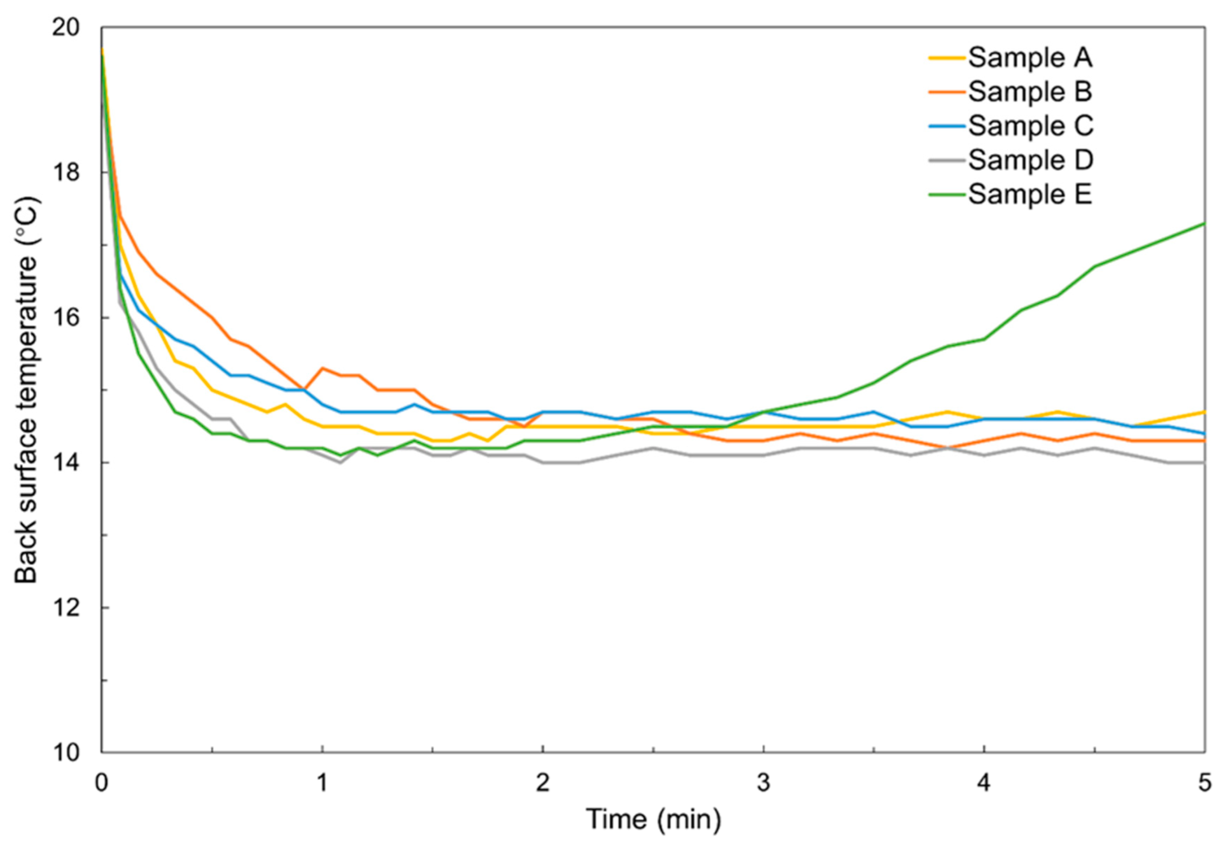
Figure 10 presents a temporal analysis of the back surface temperature of the materials at environmental conditions of 20.69 °C and 51.11% for temperature and humidity, respectively. Traditional Sample A attained its minimum back surface temperature of 14.3 °C within 1.37 min. In contrast, Samples B and C showed comparatively slower thermal response rates, requiring 2.83 and 1.83 min, respectively, to reach stable conditions owing to the increased thickness of the fabrics. During this interval, Sample B achieved the lowest back surface temperature of 14.3 °C, while Sample C recorded a value of 14.6 °C. Samples D and E, devoid of mechanical support, showcased exceptional thermal response characteristics, achieving stability within a mere 1 min timeframe. Furthermore, both materials demonstrated the ability to reach the lowest surface temperature of 14.1 °C. However, Sample E, characterised by a poor water retention capacity, maintained stability for up to 2 min only. Subsequently, the back surface temperature began to increase due to the insufficient water film coverage on the material surface.
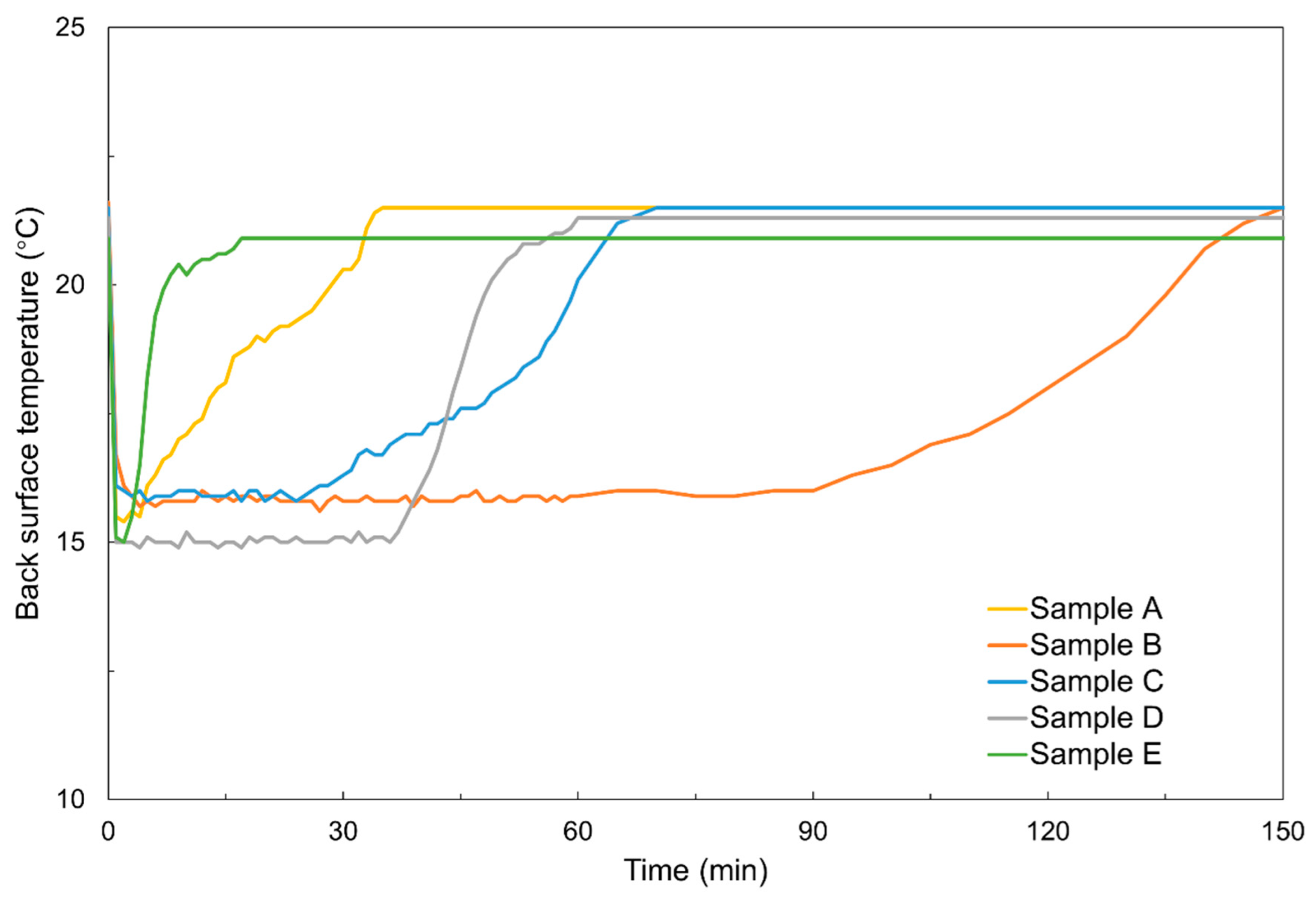
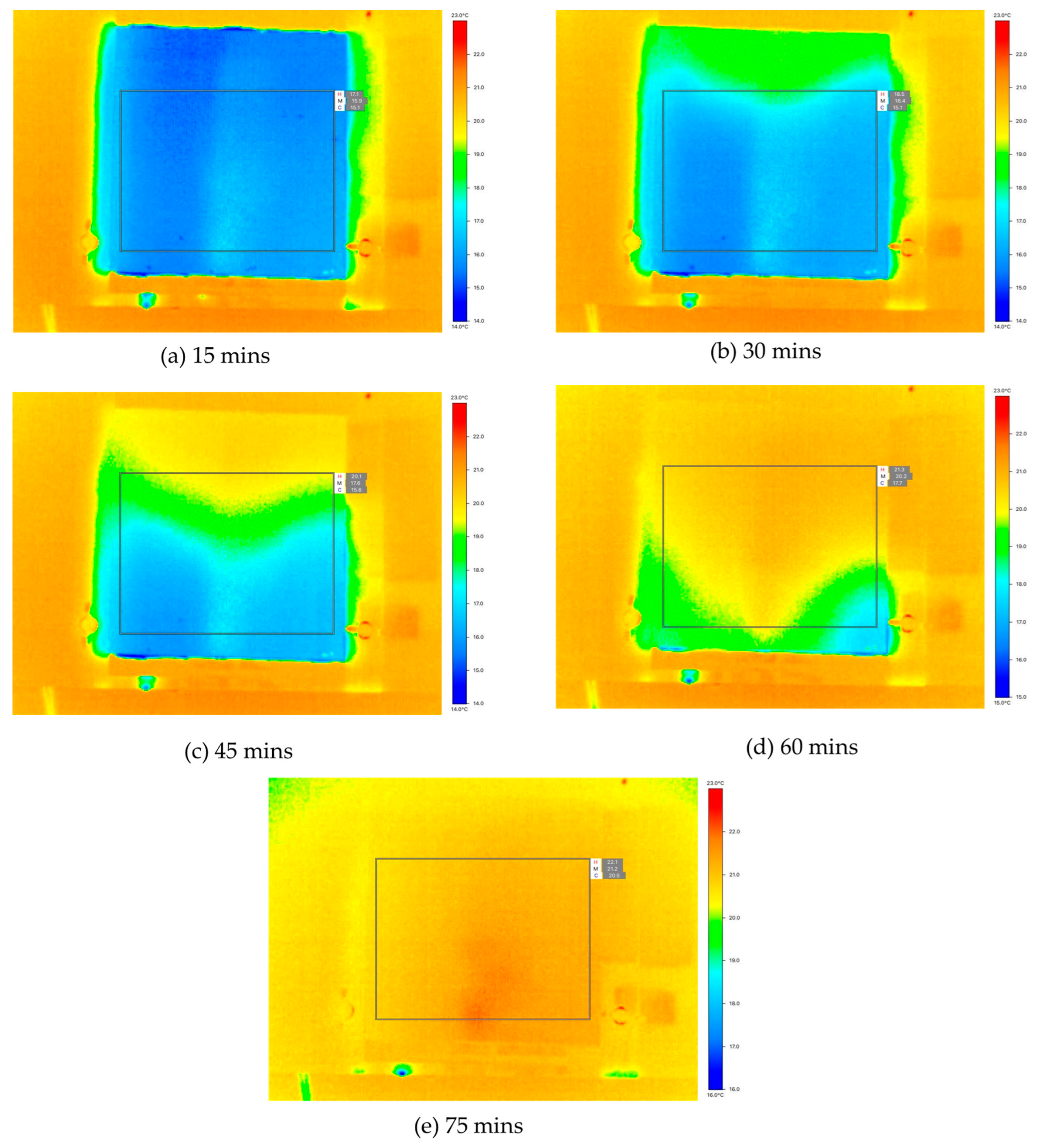
Figure 11 depicts the back surface temperatures across the entire range of material conditions, from wet to complete dryness. The measurements were conducted under ambient conditions, specifically at 21.36 °C and relative humidity of 49.01%. As a traditional material, Sample A could attain a back surface temperature of 15.5 °C for a duration of 5 min. Subsequently, the back surface temperature underwent a steady increase until it aligned with the ambient temperature, indicative of the material’s drying state. Sample B demonstrated the capability to sustain the back surface temperature at a minimal level of approximately 15.8 °C for an approximate duration of 90 min, with complete dryness achieved after 150 min. This observed phenomenon was primarily attributed to the heightened water-holding capacity of Sample B. In the case of Sample C, it was capable of attaining a comparable level of back surface temperature as Sample B. However, the temporal duration for which this temperature level was sustained was considerably shorter than that exhibited by Sample B, specifically amounting to 24 min. Samples D and E manifested the minimum back surface temperature of 15 °C among all the materials, stemming from their intrinsic characteristics that obviated the requirement for metal plates to augment mechanical reinforcement, consequently reducing overall thickness. However, there exists a notable discrepancy in the water-holding capacities of these two materials: Sample D sustained a consistent temperature level for a duration of 36 min, whereas Sample E exhibited a significantly shorter duration, lasting less than 5 min. An observed phenomenon throughout the examination indicates that the temperature distribution across a material surface exhibits non-uniformity during the evaporation process. Typical infrared images of Sample C during the evaporation process are presented in Figure 12. It is evident from the results that the upper surface of the material underwent a more rapid reduction in wettability compared with the lower section. This phenomenon can be attributed to the vertical orientation of the material because moisture tends to move downward in response to the force of gravity. This discovery can be employed to optimise IEC systems, specifically in the areas of water-spray strategy optimisation and determining the optimal orientation. For instance, future studies could investigate if a horizontal arrangement for an IEC system, combined with an intermittent water-spray strategy, would enhance the overall cooling performance compared with the conventional vertical configuration.
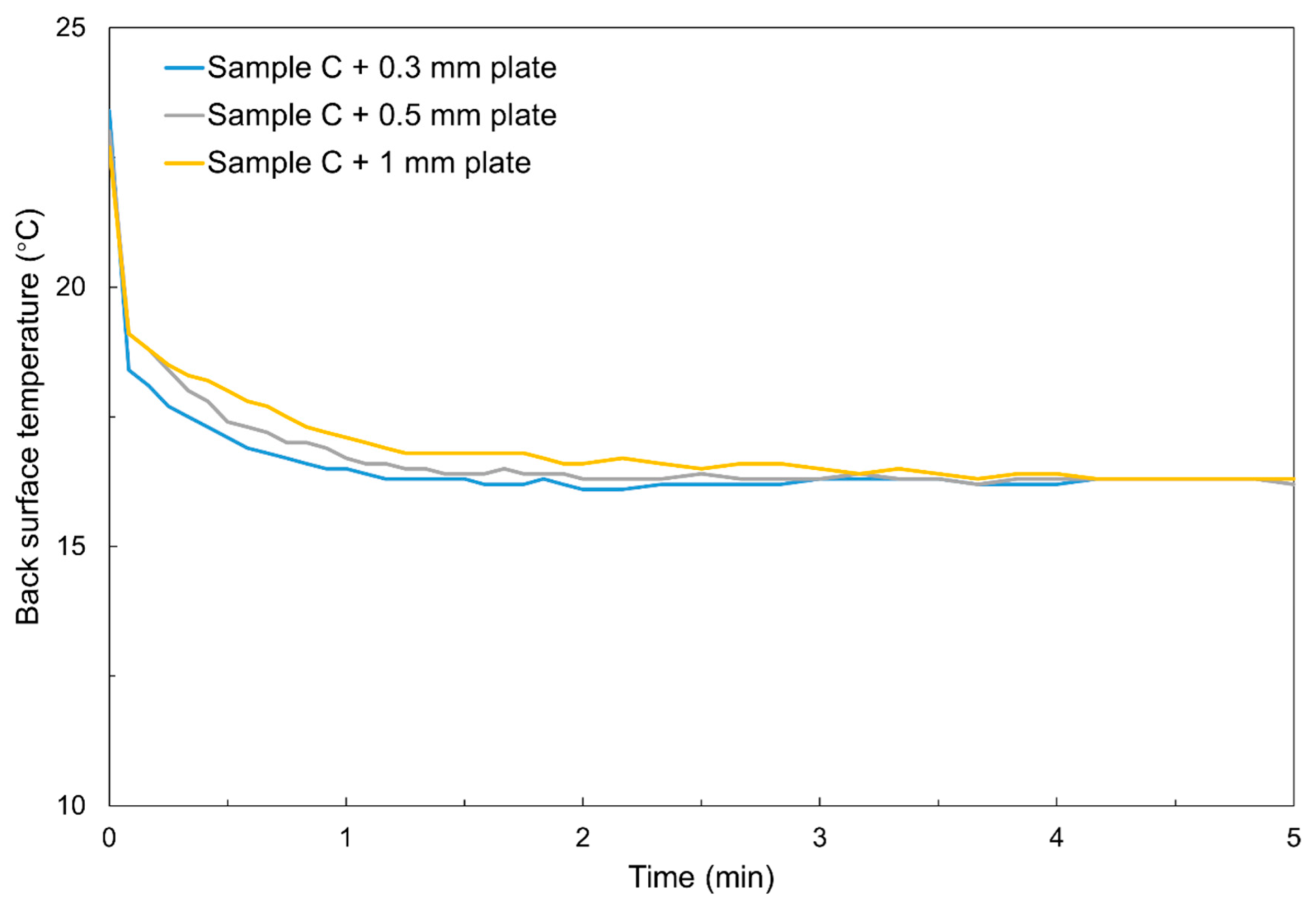
Figure 13 presents the impact of metal plate thickness on thermal response performance, with Sample C serving as a representative example under ambient conditions characterised by a temperature of 22.99 °C and relative humidity of 43.31%. As anticipated, a reduced thickness was associated with reduced thermal resistance, thereby facilitating an accelerated conduction of heat and, consequently, a more rapid decline in temperature. It was further noted that, after 4.2 min of the tests, all three plate thickness variants attained an equivalent temperature level of 16.3 °C.

4.4. Overall Comparison of the Five Materials

Based on the aforementioned test results, a synthesis of the performance of the tested samples and corresponding recommendations for a water-spray strategy are presented in Table 3. Considering the brief evaporation process, it is advisable to employ a continuous spray approach for Samples A and E. Notably, Sample E exhibits superior thermal response and mechanical strength compared with the traditional material, Sample A. However, due to the relatively low wicking and water-holding capacity of Sample E, future studies could focus on optimising the groove structures (e.g., adjusting the density and depth) to further enhance performance. Sample B demonstrates strengths across various parameters, with the sole drawback being the requisite use of a metal support plate, leading to an elevation in overall thermal resistance and system weight. Given the extended cooling duration of Sample B, an intermittent spray method is deemed suitable. Moreover, the implementation of an auto-wicking strategy for IEC utilising Sample B should be contemplated due to its exceptional wicking performance. In the case of Samples C and D, characterised by a surface temperature sustained at a low level for over 20 min, it is recommended that the intermittent spray method is adopted.

5. Conclusions and Future Works

This study presents a comparative experimental study of five wetting materials for potential application in the wet channels of indirect evaporative cooling (IEC) systems. The experiments examined wicking performance, water-holding capacity, evaporation behaviour, and thermal response, including the influence of plate thickness. The results have been distilled into insights that inform material selection and system design, which are summarised as follows:
(1)
Fabric materials (Samples B and C) showed outstanding vertical wicking ability (>16 cm) and long-term cooling stability (up to 90 min), making them highly suitable for IEC designs favouring intermittent spray strategies and extended operational periods. Sample D offered a balanced performance, combining moderate wicking with a fast and durable thermal response without the need for mechanical support plates, which makes it promising for compact or simplified IEC configurations.
(2)
The laser-resurfaced polymer (Sample E) demonstrated a fast thermal response and mechanical robustness due to its direct hydrophilic surface, eliminating reliance on supporting plates. However, its limited water retention curtailed the cooling duration, highlighting the need for further groove-structure optimisation to balance thermal efficiency and moisture storage.
(3)
From an engineering perspective, these results provide practical design recommendations. Continuous spraying is appropriate for low-retention materials (Samples A and E), while intermittent spraying is more effective for high-capacity materials (Samples B, C, and D). The observed gravitational influence on vertical moisture distribution suggests that alternative orientations (horizontal configuration) may enhance the moisture utilisation and cooling performance of IEC systems.
In summary, the laser-resurfaced polymer (Sample E) presents strong potential for IEC applications. The present work represents an early-stage investigation, and further studies will focus on developing a prototype IEC system utilising this novel material, accompanied by a comprehensive performance evaluation. In addition, the effects of different water-spray strategies on water and energy savings, as well as the long-term operational stability of the system, warrant further investigation.

Author Contributions

Conceptualization, L.L., X.W. and E.H.; methodology, L.L., X.W., E.H., G.K. and K.C.N.; formal analysis, L.L., X.W., E.H., G.K. and K.C.N.; investigation, L.L., X.W., E.H., G.K. and K.C.N.; resources, X.W. and E.H.; data curation, L.L.; writing—original draft preparation, L.L.; writing—review and editing, X.W., E.H., G.K. and K.C.N.; supervision, X.W., E.H., G.K. and K.C.N.; project administration, L.L. and X.W.; funding acquisition, X.W. All authors have read and agreed to the published version of the manuscript.

Funding

This research received no external funding.

Institutional Review Board Statement

Not applicable.

Informed Consent Statement

Not applicable.

Data Availability Statement

Data will be made available upon request.

Acknowledgments

The authors would like to thank the NCRIS and Government of South Australia-enabled Australian National Fabrication Facility—South Australian Node (ANFF-SA) for their support in this work.

Conflicts of Interest

Author Lanbo Lai was employed by Sotera Fire Engineering. The remaining authors declare that the research was conducted in the absence of any commercial or financial relationships that could be construed as a potential conflict of interest.

References

  1. Romero-Lara, M.J.; Comino, F.; de Adana, M.R. Seasonal energy efficiency ratio of regenerative indirect evaporative coolers—Simplified calculation method. Appl. Therm. Eng. 2023, 220, 119710. [Google Scholar] [CrossRef]
  2. Yan, M.; He, S.; Li, N.; Huang, X.; Gao, M.; Xu, M.; Miao, J.; Lu, Y.; Hooman, K.; Che, J.; et al. Experimental investigation on a novel arrangement of wet medium for evaporative cooling of air. Int. J. Refrig. 2021, 124, 64–74. [Google Scholar] [CrossRef]
  3. Lai, L.; Wang, X.; Kefayati, G.; Hu, E. Performance evaluation of a solar powered solid desiccant evaporative cooling system with different recirculation air ratios. Energy Build. 2022, 270, 112273. [Google Scholar] [CrossRef]
  4. Sajjad, U.; Abbas, N.; Hamid, K.; Abbas, S.; Hussain, I.; Ammar, S.M.; Sultan, M.; Ali, H.M.; Hussain, M.; Tauseef ur, R.; et al. A review of recent advances in indirect evaporative cooling technology. Int. Commun. Heat Mass Transf. 2021, 122, 105140. [Google Scholar] [CrossRef]
  5. Lai, L.; Wang, X.; Kefayati, G.; Hu, E. Evaporative Cooling Integrated with Solid Desiccant Systems: A Review. Energies 2021, 14, 5982. [Google Scholar] [CrossRef]
  6. Sun, T.; Huang, X.; Qu, Y.; Wang, F.; Chen, Y. Theoretical and experimental study on heat and mass transfer of a porous ceramic tube type indirect evaporative cooler. Appl. Therm. Eng. 2020, 173, 115211. [Google Scholar] [CrossRef]
  7. Liu, Y.; Akhlaghi, Y.G.; Zhao, X.; Li, J. Experimental and numerical investigation of a high-efficiency dew-point evaporative cooler. Energy Build. 2019, 197, 120–130. [Google Scholar] [CrossRef]
  8. Kashyap, S.; Sarkar, J.; Kumar, A. Effect of surface modifications and using hybrid nanofluids on energy-exergy performance of regenerative evaporative cooler. Build. Environ. 2021, 189, 107507. [Google Scholar] [CrossRef]
  9. Alharbi, A.; Almaneea, A.; Boukhanouf, R. Integrated hollow porous ceramic cuboids-finned heat pipes evaporative cooling system: Numerical modelling and experimental validation. Energy Build. 2019, 196, 61–70. [Google Scholar] [CrossRef]
  10. Shahzad, M.W.; Lin, J.; Xu, B.B.; Dala, L.; Chen, Q.; Burhan, M.; Sultan, M.; Worek, W.; Ng, K.C. A spatiotemporal indirect evaporative cooler enabled by transiently interceding water mist. Energy 2021, 217, 119352. [Google Scholar] [CrossRef]
  11. Gao, F.; Thu, K.; Wang, S.; Zhao, F.; Lin, J.; Wu, K. Numerical investigation of a novel tubular dew-point evaporative cooler. Appl. Therm. Eng. 2023, 223, 120064. [Google Scholar] [CrossRef]
  12. Xu, P.; Ma, X.; Zhao, X.; Fancey, K.S. Experimental investigation on performance of fabrics for indirect evaporative cooling applications. Build. Environ. 2016, 110, 104–114. [Google Scholar] [CrossRef]
  13. Khalid, O.; Butt, Z.; Tanveer, W.; Rao, H.I. Design and experimental analysis of counter-flow heat and mass exchanger incorporating (M-cycle) for evaporative cooling. Heat Mass Transf. 2016, 53, 1391–1403. [Google Scholar] [CrossRef]
  14. Lv, J.; Xu, H.; Xu, T.; Liu, H.; Qin, J. Study on the performance of a unit dew-point evaporative cooler with fibrous membrane and its application in typical regions. Case Stud. Therm. Eng. 2021, 24, 100881. [Google Scholar] [CrossRef]
  15. Abada, D.; Maalouf, C.; Sotehi, O.; Rouag-Saffidine, D.; Polidori, G.; Boudjabi, A.F.; Derghout, Z. Performance evaluation of fabrics for evaporative cooling applications. Energy Build. 2022, 266, 112120. [Google Scholar] [CrossRef]
  16. Riangvilaikul, B.; Kumar, S. An experimental study of a novel dew point evaporative cooling system. Energy Build. 2010, 42, 637–644. [Google Scholar] [CrossRef]
  17. Xu, P.; Ma, X.; Zhao, X.; Fancey, K. Experimental investigation of a super performance dew point air cooler. Appl. Energy 2017, 203, 761–777. [Google Scholar] [CrossRef]
  18. Chen, Y.; Yan, H.; Min, Y. Visualized study of wetting enhancement and thermal performance of fiber-coated indirect evaporative cooler. Appl. Therm. Eng. 2023, 221, 119904. [Google Scholar] [CrossRef]
  19. Lv, J.; Xu, H.; Zhu, M.; Dai, Y.; Liu, H.; Li, Z. The performance and model of porous materials in the indirect evaporative cooling system: A review. J. Build. Eng. 2021, 41, 102741. [Google Scholar] [CrossRef]
  20. Yang, H.; Shi, W.; Chen, Y.; Min, Y. Research development of indirect evaporative cooling technology: An updated review. Renew. Sustain. Energy Rev. 2021, 145, 111082. [Google Scholar] [CrossRef]
  21. Jia, L.; Liu, J.; Wang, C.; Cao, X.; Zhang, Z. Study of the thermal performance of a novel dew point evaporative cooler. Appl. Therm. Eng. 2019, 160, 114069. [Google Scholar] [CrossRef]
  22. Chen, Y.; Huang, X.; Sun, T.; Chu, J. Experimental study of plant fiber-polymer composite for indirect evaporative cooler application. Appl. Therm. Eng. 2021, 199, 117543. [Google Scholar] [CrossRef]
  23. Fang, R.; Zhu, H.; Li, Z.; Yan, W.; Zhang, X.; Zhu, X.; Maisotsenko, V.S.; Vorobyev, A.Y. Capillary Nylon 6 polymer material produced by femtosecond laser processing. Opt. Express 2019, 27, 36066–36074. [Google Scholar] [CrossRef] [PubMed]
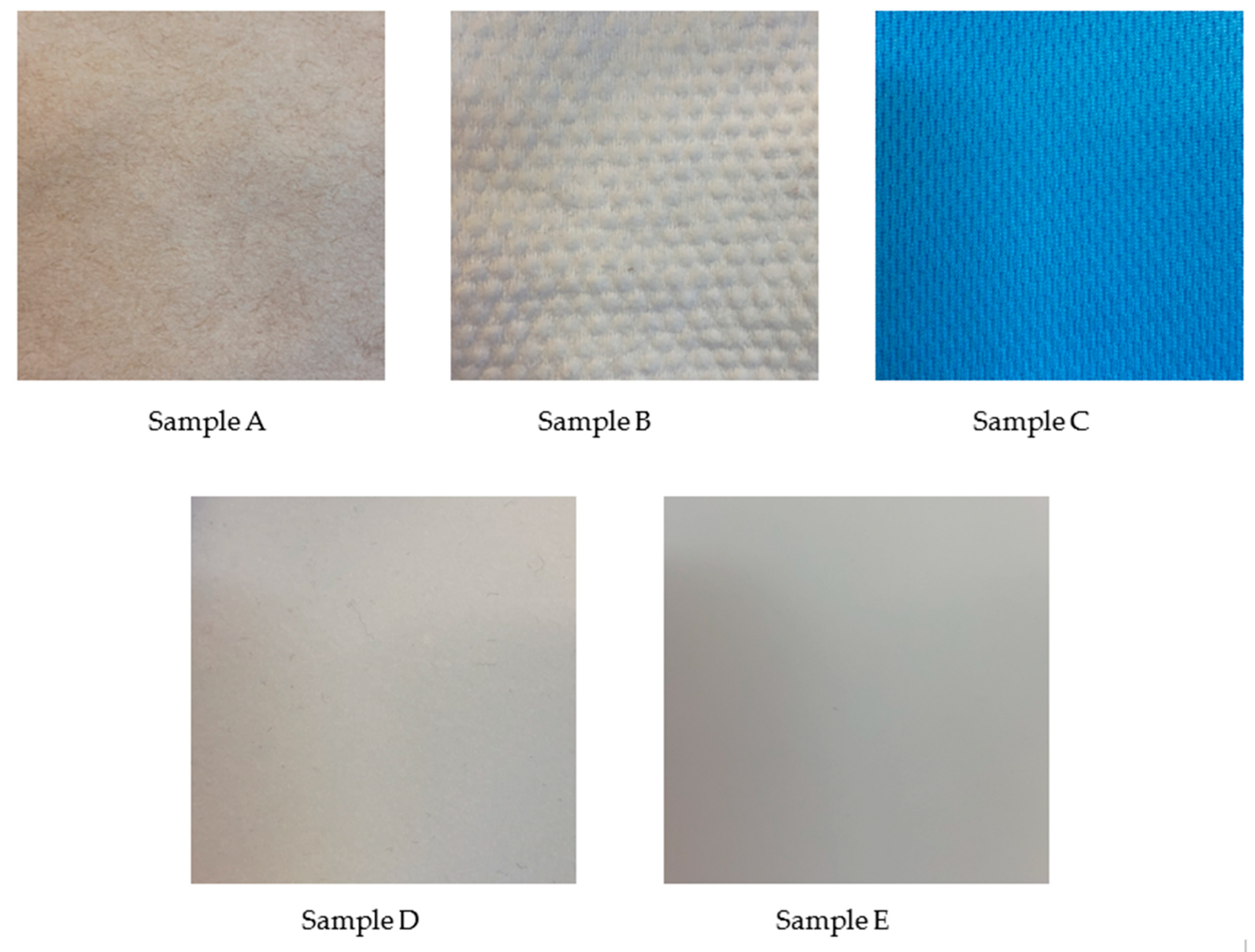
Figure 1. Photos of the selected materials.
Applsci 15 09818 g001
Figure 2. SEM images of Sample E.
Applsci 15 09818 g002
Figure 3. Wicking test setup.
Applsci 15 09818 g003
Figure 4. High-precision scale used in the tests.
Applsci 15 09818 g004
Figure 5. Conceptual design of the experimental platform.
Applsci 15 09818 g005
Figure 6. Prototype of the test rig.
Applsci 15 09818 g006
Figure 7. Results of wicking height tests carried out for 60 min.
Applsci 15 09818 g007
Figure 8. Water-holding capacity test results.
Applsci 15 09818 g008
Figure 9. Fibre distortion phenomenon observed in Sample A.
Applsci 15 09818 g009
Figure 10. Back surface temperature measurements in the initial five minutes.
Applsci 15 09818 g010
Figure 11. Back surface temperature measurements until completely dry.
Applsci 15 09818 g011
Figure 12. Thermal images documenting the evaporation process of Sample C at 15 min intervals.
Applsci 15 09818 g012
Figure 13. Effect of metal plate thickness on the thermal response of Sample C.
Applsci 15 09818 g013
Table 1. Characteristics of the selected materials.
SampleMaterial NameMaterial TypeThickness (mm)Weight (g/m2)Require Support Plates (Y/N)
AKraft paperNatural fibre0.0550Y
BCotton fibreNatural fibre0.3090Y
CPolyester fibreSynthetic fibre0.46125Y
DPolypropylene + nylon fibreComposite fibre0.40302N
ELaser-resurfaced polymer sheetResurfaced material0.50550N
Table 2. Test instruments.
Measured ParameterInstrumentRangeAccuracy
Wicking heightSteel ruler0 to 30 cm±1 mm
ThicknessCalliper0 to 15 cm±0.01 mm
Ambient temperature and relative humidityTemperature and humidity sensor (Testo 440)−20 to 70 °C
0 to 100%
±0.3 °C
±0.6%
Air velocityHot-wire anemometer (DT-8880)0.1 to 25 m/s±0.1 m/s
WeightHigh-precision scale (FZ-3000i)0 to 3200 g±0.01 g
Surface temperatureThermal imager (Testo 883)−30 to 650 °CThermal sensitivity < 0.04 °C
Table 3. A summary of tested materials and water-spray strategy suggestions.
SamplePerformance Evaluation
Wicking RateWater-HoldingMechanical StrengthThermal ResponseCooling DurationWater-Spray Strategy Recommendation
APoorPoorPoorGoodPoorContinuous spray
BExcellentExcellentPoorGoodExcellentIntermittent spray/auto-wicking
CGoodGoodPoorGoodGoodIntermittent spray
DPoorGoodExcellent *ExcellentGoodIntermittent spray
EPoorPoorExcellent *ExcellentPoorContinuous spray
* Mainly due to the dispensability of metal plates for furnishing mechanical support.
Disclaimer/Publisher’s Note: The statements, opinions and data contained in all publications are solely those of the individual author(s) and contributor(s) and not of MDPI and/or the editor(s). MDPI and/or the editor(s) disclaim responsibility for any injury to people or property resulting from any ideas, methods, instructions or products referred to in the content.