Abstract
New energy vehicles (NEVs) rely heavily on Insulated-Gate Bipolar Transistors (IGBTs) to perform frequent battery voltage conversions for operations such as acceleration, deceleration, and hill climbing. Consequently, effective thermal management of the IGBT junction temperature is critically important. This study investigates the junction temperature of IGBT modules equipped with pin-fin heat sinks of varying spacings under diverse operating conditions. The effects of the coolant inlet flow velocity and temperature on the junction temperature were examined. Furthermore, the pin-fin heat sink structure was optimized to enhance temperature uniformity across the IGBT chips. The results indicate that (1) IGBT modules with small-spacing pin-fin heat sinks exhibit improved thermal performance and enhanced temperature uniformity under specific conditions; (2) coolant inlet flow velocity is positively correlated with both module cooling efficiency and temperature uniformity; (3) coolant inlet temperature is inversely correlated with module junction temperature and chip junction temperature uniformity; and (4) among the three optimization schemes evaluated, the dual-channel, non-uniformly spaced pin-fin heat sink delivered the optimal performance, reducing the maximum junction temperature difference between IGBT chips to approximately 0.5 °C and that between diode chips to approximately 1.0 °C.
1. Introduction
The achievement of carbon neutrality and the achievement of carbon peak urgently require emission reduction efforts by the transportation sector. According to research by Tian Peining et al. [1], in 2023, China’s transportation carbon emissions accounted for 14.82% of global transportation emissions. A crucial aspect of emission reduction in the road transport industry is the widespread adoption of new energy vehicles (NEVs). New energy vehicles are typically defined as automobiles primarily powered by high-power-density batteries. Operations such as starting, stopping, accelerating, and decelerating involve frequent voltage reversals in the battery, which relies on Insulated-Gate Bipolar Transistors (IGBTs). IGBTs are widely used in applications such as frequency conversion and inversion, electric vehicles, rail transportation, smart grids, and industrial power supplies.
Motor controllers rely on IGBT modules for power conversion, and the junction temperature of these modules directly impacts their performance and lifespan. If the temperature rise in IGBT modules is not effectively controlled, failures such as solder joint cracks, bond wire surface delamination, solder foot cracks, and wire detachment gradually emerge with increasing power cycling. These types of failures are exacerbated by thermal cycling. This leads to severe thermal stress accumulation and accelerated aging in the device, ultimately causing complete IGBT failure due to overheating [2]. Therefore, predicting the junction temperature and implementing thermal management for IGBT modules are essential.
There are various cooling methods for IGBTs, which can be classified into air cooling and liquid cooling based on the type of heat transfer medium. Air cooling is the simplest and most reliable and has the lowest cost among all cooling methods. However, in most cases, the efficiency of air cooling is much lower compared to that of liquids like water [3].
Regarding the type of contact, liquid cooling can be divided into indirect cooling and direct cooling. Indirect cooling refers to the approach in which power modules have no direct contact with the coolant. A common implementation of indirect cooling is as follows: the power device is connected to the substrate via solder, while the underside of the substrate is attached with Thermal Interface Material (TIM). This stacking of multiple material layers increases the overall thermal resistance of the module [4], resulting in relatively limited heat dissipation effectiveness.
Therefore, a more prevalent cooling approach is direct liquid cooling. The key difference between this approach and indirect cooling is that the former integrates the cooling structure directly into the substrate (typically copper), eliminating the need for TIM and a separate heat sink. This can reduce the module’s thermal resistance by up to 30% [5], significantly enhancing its cooling efficiency. Depending on the cooling structure used, direct liquid cooling can be further categorized into micro-channel cooling, pin-fin cooling, and jet impingement cooling.
Micro-channel cooling is characterized by tiny channels on the cooler. During operation, a pump forces coolant through these micro-channels, where intense heat exchange with the channel walls rapidly removes heat generated by the chip or device. Using PF 5060 as the working fluid for two-phase spray cooling, the heat transfer coefficient can reach 24,000 W/m2·K [6]. While micro-channel cooling generally offers high heat dissipation efficiency, the trade-off is a significant pressure drop and corresponding increase in pumping power due to the small hydraulic diameter of the channels.
Pin-fin cooling is the most traditional and, currently, the dominant solution in the electric vehicle industry. Although not the most efficient cooling method, it features relatively low production costs and a simpler cooling system architecture, making it highly suitable for large-scale industrial applications. It is also a prominent research direction in the field of thermal management for EV IGBT modules.
Jet impingement cooling provides high heat transfer coefficients and eliminates the thermal resistance between the chip and the cooling fluid. It can achieve very low thermal resistance (typically 10−5~10−6 K·m2/W) by using impinging liquid jets [7].
Currently, finite element simulation is a popular junction temperature prediction method. Most thermal studies on IGBT modules in the past five years were completed using finite element simulation tools.
Sun Zhiyu [8] used ANSYS Icepack 18.1 to model IGBT modules, comparing finite element simulation results of the IGBT junction temperature under steady-state conditions with online test experimental results, which verified the feasibility and accuracy of the proposed multi-model junction temperature estimation method. Zhang Rufang [9] used ANSYS finite element analysis software as a platform to study the thermal conductivity of composite materials, the heat dissipation performance of IGBT modules, and thermal stress. Based on the calculated maximum junction temperature and maximum thermal stress results of the IGBT module package, recommendations for heat dissipation design and structural optimization were proposed. Sun Haifeng et al. [10] used COMSOL to model and simulate IGBT chips and their heat dissipation substrates, analyzing the thermal efficiency of IGBTs under single and periodic power pulses. However, the research object was only a single IGBT chip, and the geometric modeling was overly simplistic, limiting its reference value. He Mengyu et al. [11] used finite element simulation software to explore the impact of bond wire and solder layer aging on IGBT module junction temperature calculation and experimentally verified the accuracy of the proposed junction temperature calculation model.
However, the disadvantage of finite element simulation should not be ignored. In the case of free convection, the accuracy of the thermal simulations is limited by challenges in estimating the convective heat transfer coefficient (h) and accounting for the temperature dependence of thermal conductivities. As a result, the thermal resistances of the module are often treated as constant in simulations, whereas they vary in actual situations [12].
The main research content of this study is the examination of the effects of the cooling pin-fin arrangement, coolant flow velocity, and coolant inlet temperature on the IGBT junction temperature under various working conditions. Additionally, some optimal pin-fin arrangement strategies have been investigated. The dual-flow-channel non-uniform pin-fin arrangement scheme proposed in this study can reduce the maximum junction temperature of IGBT chips by 3 °C compared to the widely used single-flow-channel uniform pin-fin design while also achieving a 6 °C reduction in the maximum junction temperature difference among IGBT chips. Moreover, improvements are demonstrated in both the junction temperature and temperature uniformity of diodes.
In recent years, many studies on pin-fin optimization have focused on reducing the junction temperature of IGBT modules by altering pin-fin shapes, distribution density, and arrangement angles [13,14,15,16,17,18], often overlooking the issue of junction temperature uniformity. The non-uniform pin-fin arrangement proposed in this study effectively enhances the heat dissipation conditions for IGBT chips with higher power losses. The rational design of pin-fin spacing significantly improves chip junction temperature performance while effectively controlling the increase in coolant pressure drop. The dual-flow-channel coolant passage design effectively mitigates the reduction in the convective heat transfer efficiency caused by the gradual temperature rise of the coolant along the flow path, thereby addressing the issues of increased chip junction temperature and worsened temperature uniformity.
2. Research Methods
2.1. Geometric and Physical Models
The geometric modeling of the IGBT module was completed in SolidWorks 2025. Due to the negligible impact of the bond wires and surrounding encapsulation on the IGBT junction temperature [19], these components were omitted during modeling. The IGBT module model was constructed, with the solder layer explicitly modeled as a solid entity. Detailed model parameters are listed in Table 1. Orthographic views and an isometric projection of the IGBT module are shown in Figure 1 below. After assembling all components, the assembly was exported in Parasolid format and imported into COMSOL.

Table 1.
IGBT module geometry parameters.
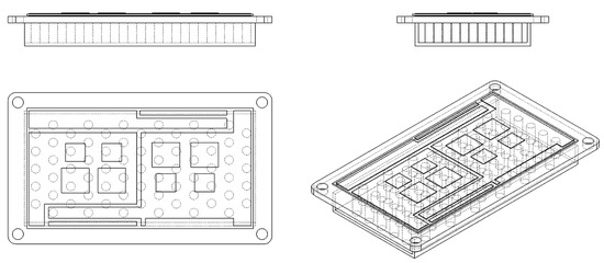
Figure 1.
IGBT module’s orthographic views and isometric projection.
To ensure the accuracy of the simulation results, the flow regime of the coolant within the channels must be determined to guarantee the appropriate simulation interface is selected in the finite element analysis software. The Reynolds number is widely regarded as a critical parameter for characterizing the flow regime. Typically, a value of 2300 is considered the transition point where flow shifts from laminar to turbulent. Thus, the Reynolds number must be calculated. Under consistent other conditions, the Reynolds number is directly proportional to the fluid flow velocity. Therefore, it is sufficient to perform the calculation for the scenario with the highest flow rate. For the acceleration condition (the operating condition with the highest coolant inlet flow velocity) using both the 4 mm spacing and 2 mm spacing pin-fin arrangements, the Reynolds numbers at the outlet were calculated as 1430.2 and 1756.1, respectively. Both Reynolds numbers are below 2300, which indicates that the Laminar Flow interface is valid. Further calculations revealed that the flow remained laminar in all other simulations except for the two cases within the flow velocity variation study, specifically, the 0.35 m/s and 0.4 m/s conditions. In these two cases, the Re value at the channel outlet exceeded 2300, indicating turbulent flow. This implies that at both flow velocities, the COMSOL simulations require the additional introduction of a turbulence interface. The governing equations involved are as follows:
Continuity Equation:
Momentum Equation:
Both equations are written for the steady-state case, neglecting the time constant τ. is the fluid density; , are the fluid velocities in the x, y, and z directions, respectively (components of the velocity vector u); and , , and are the thermal conductivities of the material in the x, y, and z directions, respectively. The materials used in this study are isotropic; hence, their thermal conductivity is identical in all directions. T is temperature, and Q is the internal heat source.
2.2. Power Loss Data Acquisition
During operation, both IGBT chips and diode chips generate a significant amount of heat originating from their power losses. These losses primarily consist of conduction losses and switching losses. To obtain more accurate chip-level power loss data, this study employs IPOSIM for the simulation of the IGBT module.
The IGBT module operates under three primary working conditions characterized by high power and substantial heat generation: constant-speed driving, acceleration, and hill climbing. Under these conditions, the electrical parameters of the IGBT chips and diode chips exhibit distinct characteristics. During constant-speed driving, the vehicle requires stable and relatively low torque, resulting in a consistently low output current, stable output frequency, low switching frequency, and high power factor. Under this condition, energy utilization efficiency is maximized. During acceleration, the torque may reach its peak value, leading to a high output current. This condition represents the period of highest power dissipation in the IGBT. Simultaneously, the output frequency and modulation index remain at elevated levels. During hill climbing, the demanded torque is high and stable—similar to the constant-speed condition but under significantly increased load. The output current remains continuously elevated. Due to the low vehicle speed, the output frequency is relatively low; however, the high current emphasizes the inductive characteristics of the motor, resulting in a noticeably reduced power factor.
The selected topology is the single-phase inverter topology, consistent with the simulation module (as shown in Figure 2), with a DC bus voltage of 400 V, which represents the most commonly used 400 V platform in electric vehicles. By adjusting the output current, output frequency, switching frequency or modulation index, and power factor according to the parameter characteristics of different operating conditions (specific settings are detailed in Table 2), this setup enables the acquisition of loss data for IGBT chips and diode chips under various operating conditions, as summarized in Table 3.

Figure 2.
IGBT circuit core module schematic diagram and schematic diagram of chip distribution.

Table 2.
IPOSIM simulation setting.

Table 3.
IPOSIM simulation results.
2.3. Parameter Settings
Five materials were utilized in this study: copper, silicon, alumina (Al2O3), a solder layer, and a 50% propylene glycol aqueous solution. The material properties for copper and silicon were obtained directly from the COMSOL built-in material library. The properties for alumina, the solder layer, and the 50% propylene glycol aqueous solution were sourced from the relevant literature [20,21]. Specific material property settings are provided in Table 4 below.

Table 4.
Material property settings in COMSOL.
The simulation interfaces employed were Heat Transfer in Solids and Fluids and Laminar Flow. In the Heat Transfer in Solids and Fluids interface, two “Heat Rate” heat sources were added, corresponding to the losses of the IGBT chip and diode chip.
2.4. Meshing and Mesh Independence Verification
For meshing, using the 4 mm spaced pin fin under acceleration conditions as an example, a layered mesh was created using Extra-Fine Free Triangular meshing combined with a sweep operation (sweep distribution: fixed number of elements = 3). For the thicker copper heat sink where sweeping was not feasible, a layered mesh was achieved using Extra-Fine Free Triangular meshing combined with a boundary layer (number of layers: 2; stretching factor: 1; thickness adjustment factor: 6). For the fluid domain, boundary layers were applied at the inlet and outlet. The fluid volume was meshed using Free Tetrahedral elements, calibrated for Fluid Dynamics with a finer predefined size. The remaining domains were meshed with finer Free Tetrahedral elements. The completed mesh consisted of 1,174,157 elements in total. The element quality histogram shows excellent mesh quality.
Mesh independence verification was also performed on the 4 mm spaced pin fin under acceleration conditions. Six datasets were simulated by varying mesh refinement to cover a range of element counts, from 940,000 to 2,100,000 elements, as detailed in Table 5 below.

Table 5.
Mesh independence verification.
The IGBT junction temperature for the 940,000-element mesh differed by 0.8%, and the diode junction temperature differed by 0.7% compared to the result from the 1,174,000-element mesh. The IGBT junction temperature for the 2,100,000-element mesh differed by 0.03%, and the diode junction temperature differed by 0.1% compared to the results from the 1,174,000-element mesh. These results successfully verified mesh independence.
3. Results and Discussion
The pin fins are all cylindrical with a diameter of 4 mm and a height of 9 mm, arranged in a staggered pattern aligned with the coolant flow direction. The two arrangements feature center-to-center spacings of 4 mm and 2 mm between adjacent pin fins. The pin fins are uniformly distributed across the underside of the copper heat sink, serving as the primary heat transfer surface for the entire DBC (Direct-Bonded Copper) area.
The operating conditions are simulated by directly modifying the power dissipation of the IGBT chips and diode chips. In practical applications, the IGBT module is encapsulated with potting materials, causing most of the heat generated by the module to be dissipated through the heat sink located beneath it. Therefore, heat dissipation via radiation to the surrounding environment is negligible and is thus not considered in the simulation.
3.1. Junction Temperature Distribution of 4 mm and 2 mm Spaced Pin Fins Under Three Operating Conditions
As shown in the temperature contour maps for the three operating conditions in Figure 3, temperature non-uniformity becomes increasingly pronounced from low-load conditions (constant-speed operation) to high-load conditions (slope-climbing and accelerating operations). Numbering the IGBT chips (larger) and diode chips (smaller) from left to right, the junction temperatures of IGBT3 and IGBT4 are significantly higher than those of IGBT1 and IGBT2. The diode chips exhibit the same trend, with chips near the channel outlet showing markedly higher junction temperatures than those near the inlet.
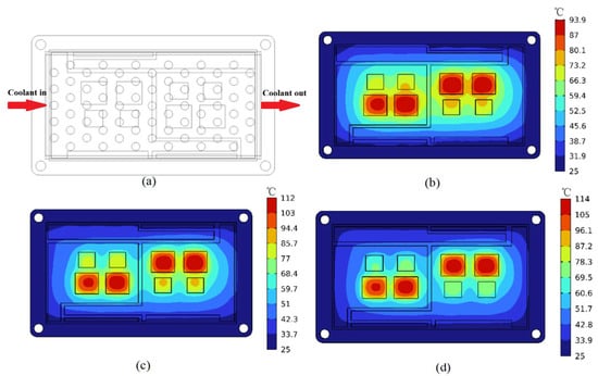
Figure 3.
(a) IGBT module pin-fin layout schematic (4 mm pitch pin fin) and module junction temperature distribution for (b) constant-speed condition; (c) grade-climbing condition; and (d) acceleration condition.
Compared to the slope-climbing and accelerating conditions, the difference in power dissipation between the IGBT and diode chips is smaller under constant-speed operation. The overall temperature distribution across the DBC appears relatively uniform in the contour map, with thermal gradients radiating evenly outward from the four pairs of IGBT and diode chips. As the operating conditions change and chip power dissipation increases, progressing from constant-speed to slope-climbing and then to accelerating conditions, the disparity between IGBT and diode losses widens, and the temperature distribution across the substrate becomes increasingly uneven. This indicates that higher chip power dissipation elevates the risk of DBC substrate deformation and promotes greater generation and accumulation of thermal stress.
Figure 4 displays the temperature contour maps for the IGBT module with 2 mm spaced pin fins under three operating conditions. The temperature distribution pattern is fundamentally consistent with that of the 4 mm spaced pin-fin module.
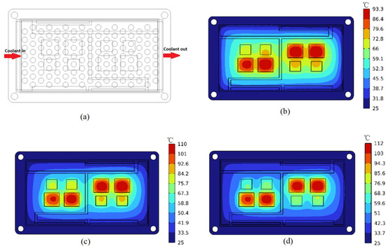
Figure 4.
(a) IGBT module pin-fin layout schematic (2 mm pitch pin fin) and module junction temperature contour plots for (b) constant-speed condition; (c) grade-climbing condition; and (d) acceleration condition.
Figure 4 compares the junction temperatures of IGBT chips and diode chips between the 4 mm spaced and 2 mm spaced pin-fin modules under three operating conditions. Figure 3b,c compare IGBT and diode chip temperatures under constant-speed operation. For IGBT junction temperatures, the 2 mm spaced module shows significantly lower temperatures than the 4 mm spaced module. The average IGBT junction temperature for the 4 mm spaced module is 93.04 °C, while it is 91.83 °C for the 2 mm spaced module—a reduction of 1.21 °C. For diode chips, the difference is minimal: the 4mm spaced module averages 74.03 °C versus 73.98 °C for the 2 mm spaced module, a mere 0.05 °C difference. Despite this small gap, temperature uniformity improves slightly for diode chips 2, 3, and 4. Regarding the maximum junction temperature rise above ambient for IGBT chips, the value for the 4 mm spaced module is 93.9 °C, while that for the 2 mm spaced module is 91.6 °C. For diode chips, the corresponding values are 67.7 °C and 66.9 °C for the 4 mm and 2 mm spaced modules, respectively.
The 2 mm spaced pin fins reduce the average IGBT junction temperature by 2.07 °C across all three conditions compared to the 4 mm spacing, while diode temperatures decrease by 0.88 °C. This demonstrates that smaller pin-fin spacing helps reduce chip junction temperatures. Regarding temperature uniformity, although the 2 mm spacing reduces the maximum temperature difference () for some chips under certain conditions, the average for IGBT chips increases to 5.32 °C (vs. 5.16 °C for 4 mm spacing—a 0.16 °C rise). For diodes, the average rises to 6.31 °C (vs. 5.90 °C for 4 mm—a 0.41 °C increase). This indicates that reducing pin-fin spacing generally has a negative impact on junction temperature uniformity.
Therefore, the results reveal that modules with 2 mm spaced pin fins exhibit lower junction temperatures for both IGBT and diode chips across all three operating conditions compared to the 4 mm spaced configuration. However, the 2 mm spaced modules demonstrate poorer temperature uniformity and result in a significantly higher inlet–outlet pressure drop than their 4 mm spaced counterparts.
3.2. Effects of Coolant Flow Rate and Temperature on Junction Temperature with Pin-Fin Optimization
3.2.1. Influence of Flow Rate on Junction Temperature
The accelerating condition with the highest chip power dissipation was selected, where the IGBT chip power dissipation was 232.88 W and the diode chip power dissipation was 49.09 W. To eliminate interference from other variables, the coolant inlet temperature was maintained constant at 50 °C, while the flow rate varied from 0.1 m/s to 0.4 m/s in 0.05 m/s increments, resulting in seven distinct datasets, as shown in Figure 5.
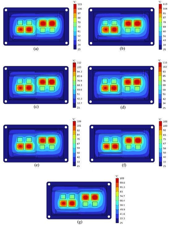
Figure 5.
Contour plots of module junction temperature under different coolant inlet velocities: (a) 0.1 m/s; (b) 0.15 m/s; (c) 0.20 m/s; (d) 0.25 m/s; (e) 0.30 m/s; (f) 0.35 m/s; and (g) 0.40 m/s.
As shown in Figure 5a–g, the temperature of the DBC substrate between the two sets of IGBT and diode chips gradually decreases with increasing coolant inlet flow rate. From 0.1 m/s to 0.3 m/s, the temperature drops from approximately 70 °C (similar to the chip periphery) to about 50 °C, thus causing the junction temperatures of the left and right chip sets to gradually decouple and forming a significant thermal gradient in between. This indicates that higher flow rates lead to an increasingly uneven temperature distribution across the DBC substrate, resulting in greater generation and accumulation of thermal stress. Elevated flow rates thus pose risks of DBC substrate warpage deformation and reduced service life. Figure 6 shows that the highest IGBT junction temperature consistently occurs at chip IGBT4 near the coolant outlet. This temperature decreases from 115.49 °C at 0.1 m/s to 107.84 °C at 0.4 m/s. Similarly, diode chip 4 exhibits the highest junction temperature among all diodes, decreasing from 80.18 °C to 74.55 °C over the same flow rate range.
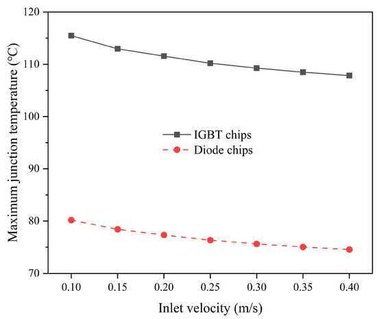
Figure 6.
Junction temperatures of chips under different coolant inlet velocities.
The maximum temperature difference (ΔT) between chips also exhibits an inverse relationship with the flow rate: IGBT ΔT decreases from 7.25 °C to 5.19 °C; diode ΔT decreases from 8.17 °C to 5.98 °C. This demonstrates improved chip temperature uniformity at higher coolant flow rates. The fluid temperature rise decreases with increasing flow rate, dropping from 5.65 °C to 2.992 °C, thereby reducing the thermal load on the coolant circulation system’s condenser. However, the inlet–outlet pressure drop increases substantially with the flow rate, rising from 818 Pa at 0.1 m/s to 12,264 Pa at 0.4 m/s—a 15-fold increase. This imposes significant challenges on pump performance requirements.
Figure 7 depicts the maximum ΔT between chips at different flow rates, showing an inverse linear relationship within the simulated range. As the flow rate increases, ΔT decreases almost linearly.
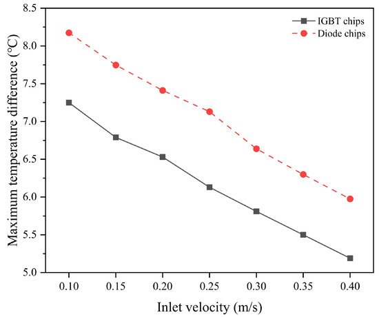
Figure 7.
Maximum temperature difference among chips under different coolant inlet velocities.
Figure 8 and Figure 9 illustrate the trends of fluid temperature rise and pressure drop versus the inlet flow rate, respectively. The fluid temperature rise is inversely proportional to the flow rate, while the pressure drop is directly proportional. Both follow parabolic relationships: the temperature rise decreases at a diminishing rate with increasing flow rate, whereas the pressure drop increases at an accelerating rate, particularly above 0.3 m/s, where the flow transitions from laminar to turbulent, further amplifying the pressure rise gradient.
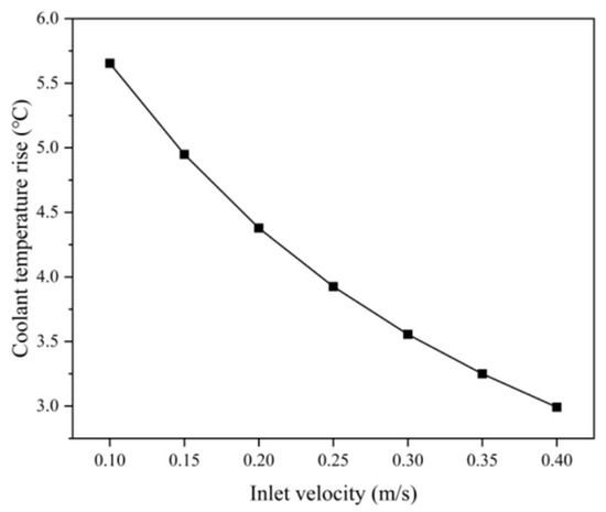
Figure 8.
Coolant temperature rise under different coolant inlet velocities.
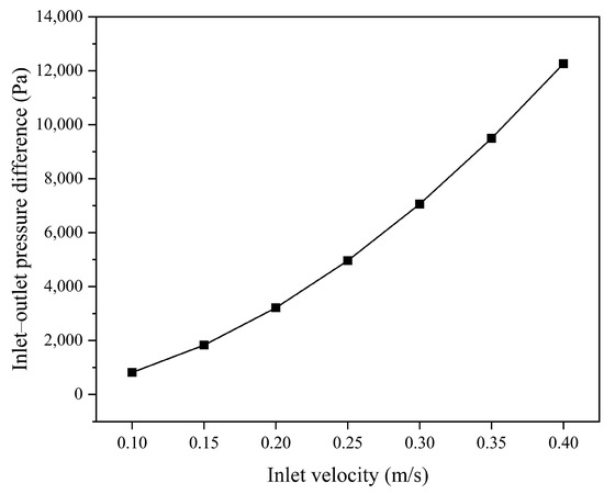
Figure 9.
Inlet–outlet pressure drop under different inlet velocities.
3.2.2. Effect of Coolant Temperature on Junction Temperature
Here, the chip junction temperature behavior under varying coolant temperatures was investigated. Simulations were conducted on the IGBT module with 2 mm spaced pin fins under accelerating conditions. With the coolant inlet flow rate fixed at 0.2 m/s, the inlet temperature was increased from 40 °C to 70 °C in 5 °C increments, generating seven datasets, as shown in Figure 10.
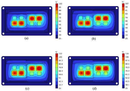
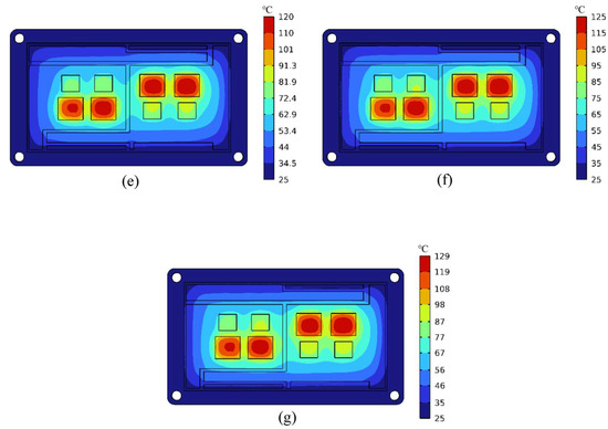
Figure 10.
Contour plots of module junction temperature under different coolant inlet temperatures: (a) 40 °C; (b) 45 °C; (c) 50 °C; (d) 55 °C; (e) 60 °C; (f) 65 °C; and (g) 70 °C.
Figure 10 shows the module junction temperatures at different coolant inlet temperatures. As the inlet temperature increases, the DBC substrate temperature between the two chip sets rises progressively from approximately 60 °C to approximately 80 °C. Temperatures adjacent to chips become increasingly similar, resulting in more uniform thermal distribution across the central DBC region. The heat dissipation evolves toward a pattern radiating outward from the eight central chips. This enhanced substrate temperature uniformity helps mitigate central deformation risks. However, the maximum IGBT junction temperature rises sharply—from 103 °C with 40 °C coolant to 129 °C with 70 °C coolant. This approaches the design limit of 150 °C for the virtual junction temperature. Considering extreme operating scenarios, the 129 °C junction temperature with 70 °C coolant offers insufficient margin and falls outside the recommended operating range.
Figure 11 shows that the maximum junction temperatures increase linearly with the inlet temperature. Under a 30 °C increase in the coolant temperature, the IGBT temperature rises by 25.9 °C and the diode temperature by 25.2 °C.
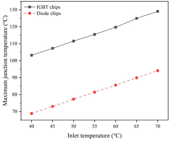
Figure 11.
Junction temperatures of chips under different coolant inlet temperatures.
Lower coolant inlet temperatures improve three key parameters: lower junction temperatures, enhanced temperature uniformity, and decreased condenser load. However, practical constraints must be considered, such as ambient temperatures around IGBT modules and coolant systems; non-insulated coolant piping and equipment; system efficiency (COP) requirements; and component longevity concerns. Therefore, an appropriate inlet temperature must be selected through system-level trade-offs to optimize both module performance and coolant system efficiency.
3.3. Pin-Fin Optimization Solution
The junction temperature uniformity of IGBT modules is a critical indicator for predicting module lifespan. Junction temperature uniformity refers to the consistency of junction temperatures across IGBT chips—the smaller the temperature difference between chips, the better the uniformity. Poor temperature uniformity may cause chips operating at higher temperatures to degrade faster than others during prolonged power cycling, ultimately reducing the overall lifespan of the IGBT module and triggering premature failure. Therefore, ensuring junction temperature uniformity is a key consideration when designing IGBT thermal solutions. Thus, the targeted optimization of pin-fin structures is therefore essential to improve junction temperature uniformity in IGBT modules. This section proposes three pin-fin optimization schemes: single-channel non-uniform pin-fin arrangement based on 2 mm spacing; dual-channel uniform pin-fin arrangement with 2 mm staggered spacing; and dual-channel non-uniform pin-fin arrangement. All simulations maintained the accelerated-condition parameters for the 2 mm spaced pin-fin baseline: a coolant inlet flow velocity of 0.2 m/s; a coolant inlet temperature of 50 °C; and IGBT module power losses set to accelerated-operation values.
3.3.1. Single Flow Channel with Non-Uniformly Distributed Pin Fins
Although the pin fins in the previous sets of simulations have different spacings, they are all uniformly arranged in a staggered pattern directly beneath the DBC substrate. Such an arrangement may prevent IGBT chips which have a relatively higher heat flux from obtaining sufficient heat transfer area for cooling, and this situation becomes exacerbated in the downstream sections of the flow channels where fluid temperatures are elevated. As observed from previous simulations, the junction temperatures of both IGBT chips and diode chips that are close to the outlet of the channels are evidently higher than those close to the inlet. Therefore, the lack of heat transfer area might be the main reason for the poor performance of chip junction temperature uniformity in the previous simulations.
To address this problem, the design of the 2 mm spaced pin-fin module was modified: the pin fins directly beneath the four IGBT chips were replaced with smaller-diameter, more densely packed pin fins. This enhances the effective heat transfer area for the IGBT chips, aiming to improve junction temperature uniformity across the module. The specific pin-fin arrangement is as follows: 3 mm diameter, 9 mm high cylindrical pin fins were staggered along the flow direction at 1.5 mm intervals; 2 mm diameter cylindrical pin fins were added to fill the larger gaps between the 4 mm and 3 mm diameter pin fins, ensuring overall flow uniformity. The pin-fin layout is illustrated in Figure 12 below. From the temperature contour plot in Figure 13, the following observations are noted: the peak junction temperature is 113 °C. Junction temperature uniformity across the chips did not show significant improvement. The junction temperature in the DBC substrate region between the two sets of chips is higher than in the uniformly spaced (2 mm) module. Temperature uniformity across the DBC substrate improved slightly.

Figure 12.
Schematic diagram of non-uniform-pitch pin-fin arrangement in single-channel flow.
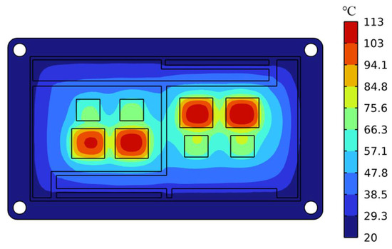
Figure 13.
Contour plot of junction temperature for single-channel module with non-uniform pin-fin arrangement.
The results showed that the maximum temperature difference between diode chips decreased from 7.41 °C to 6.69 °C (a reduction of 0.72 °C). Under identical coolant inlet velocity and temperature conditions, the pressure drop increased slightly from 3215.7 Pa to 3231 Pa, and the coolant temperature rise increased marginally from 4.38 °C to 4.81 °C. Notably, the minor increases in the pressure drop and temperature rise yielded significant improvements in diode temperature uniformity.
However, regarding chip junction temperatures, Figure 14 reveals that junction temperatures for both IGBT and diode chips in the optimized design exceed those of the original design: The peak IGBT junction temperature rose from 111.57 °C to 112.64 °C (↑ 1.07 °C). The diode junction temperature surged from 77.344 °C to 82.032 °C (↑ 4.688 °C). The maximum temperature difference across IGBT chips reached 6.95 °C (↑ 0.42° C vs. baseline). These results indicate that the optimization design adversely impacted thermal performance.
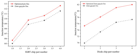
Figure 14.
Comparison of IGBT and diode junction temperatures between single-channel modules with non-uniform and uniform pin-fin arrangements.
3.3.2. Dual Flow Channels with Uniformly Distributed Pin Fins
Although the previous optimization improved the junction temperature uniformity of the diode chips, the excessively narrow spacing of the pin fins beneath the IGBT chips led to flow reversal and coolant stagnation. This resulted in increased junction temperatures of the chips and persistent temperature rise along the coolant flow direction. To address this issue, this solution proposes a dual-flow-channel design from the outset. The pin-fin arrangement and flow direction schematic are shown in Figure 15 below.

Figure 15.
Schematic of dual-channel uniform-pitch pin-fin arrangement.
The flow channel is divided into two adjacent channels along the long edge of the module, separated by a 1.5 mm thick copper plate. Each channel cools one set of IGBT and diode chips on either side, with counter-flowing coolant in the two channels. This ensures that the coolant first passes the IGBT chips before cooling the diode chips, which allows the IGBT chips to receive priority cooling, thereby achieving lower junction temperatures. Additionally, it contributes to a more uniform tangential temperature distribution within the same channel, leading to effective improvement in junction temperature uniformity of IGBT module chips. The pin-fin specifications are as follows: cylindrical pin fins with 4 mm diameter × 9 mm height, in a uniform, staggered arrangement with 2 mm spacing along the flow direction. As clearly shown in Figure 16, the peak junction temperature of IGBT chips decreased to approximately 109 °C; the temperature contours of the left and right IGBT/diode chip sets are highly similar and symmetrical; and the overall junction temperature uniformity of the chips is significantly better than in all previous solutions.
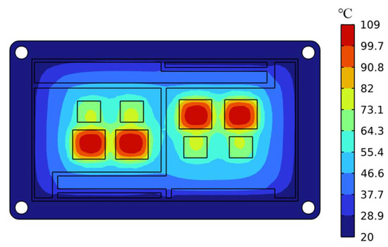
Figure 16.
Contour plot of junction temperature for dual-channel uniform-pitch pin-fin module.
A comparison between the optimized dual-flow-channel module with uniformly spaced pin fins and the original design shows that the peak junction temperatures for both IGBT and diode chips occur at central chips 2 and 3, attributable to the thermal coupling effects between chips. Additionally, peak temperatures showed significant improvements, as follows: IGBT: 108.55 °C (↓ 3.02 °C from original 111.57 °C); diode: 75.587 °C (↓ 2.243 °C from original 77.344 °C). The single-channel pressure drop decreased from 3215.7 Pa to 1927 Pa, though the total pumping power increased.
As shown in Figure 17, junction temperature uniformity is markedly superior in the optimized design. Chips 1–2 in the original design exhibit lower or approximately equal temperatures compared to the optimized design.
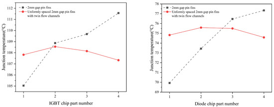
Figure 17.
Comparison of IGBT and diode junction temperatures between dual-channel uniform-pitch pin-fin module and baseline scheme.
Despite identical inlet velocities, the optimized channel cross-section is smaller than the original. This results in a difference in the coolant flow rates between the two designs: the optimized design has a flow rate of 4.15 L/min, while that of the original is 5.4 L/min. Consequently, the cooling capacity at the inlet is reduced in the optimized design, resulting in higher junction temperatures for chips 1–2.
As the results show, junction temperatures are influenced by the collective effects of the pin-fin arrangement, the coolant flow behavior, thermal coupling, and the effective heat dissipation area. Therefore, thermal management designs for IGBT modules must account for these interdependent factors.
3.3.3. Dual Flow Channels with Non-Uniformly Distributed Pin Fins
This subsection further optimizes the dual-flow-channel design with uniformly arranged pin fins. As shown in Figure 18, the pin fins directly beneath IGBT chips are replaced with cylindrical pin fins (3 mm diameter × 9 mm height) at 1.5 mm intervals. Compared to the single-flow-channel non-uniform arrangement, the spacing between the 3 mm and 4 mm diameter pin fins is more reasonable; excessively large gaps remain filled with 2 mm diameter pin fins. For IGBT chips operating long-term at elevated temperatures, temperature uniformity is critical. This design adjustment aims to further reduce IGBT junction temperatures and enhance junction temperature uniformity.

Figure 18.
Schematic of dual-channel non-uniform-pitch pin-fin arrangement.
Figure 19 shows the junction temperature contour plot of this optimized design: the peak module junction temperature reaches approximately 108 °C (lower than previous designs), and the temperature distribution characteristics are relatively similar to the prior optimized solution. This demonstrates that the pin-fin arrangement is more rational than the single-flow-channel non-uniform configuration, achieving the preliminary objectives.
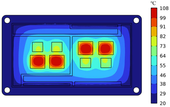
Figure 19.
Contour plot of junction temperature for dual-channel non-uniform-pitch pin-fin module.
The temperature performance of this optimized design is as follows: the peak IGBT junction temperature is 108.32 °C (a decrease of 3.25 °C compared to the original 111.57 °C), and the peak diode junction temperature is 75.713 °C (a decrease of 1.631 °C). Compared to the previous optimized design, the IGBT temperature decreased by 0.23 °C, while the diode chip’s maximum temperature increased slightly by 0.126 °C.
The junction temperature uniformity of the IGBT chips shows further improvement, and the diode chips’ temperature increase is negligible. As shown in Figure 20, the IGBT chips exhibit significantly enhanced uniformity compared to the original design. Chips 1, 2, and 3 show nearly identical temperatures. The slight rise in chip 3’s temperature is likely due to the combined effects of thermal coupling and the effective heat dissipation area. And the diode temperature distribution aligns with the previous optimized design: central chips 3–4 show higher temperatures than chips 1–2. This might be attributable to lower heat dissipation in diodes and stronger influence of thermal coupling.
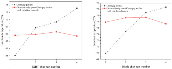
Figure 20.
Comparison of IGBT and diode junction temperatures between dual-channel non-uniform-pitch pin-fin module and baseline scheme.
3.3.4. Performance Comparison of Optimized Pin Fins
Figure 21 and Figure 22 compare the junction temperatures of the IGBT and diode chips across three optimization schemes. The first optimization scheme is excluded from comparison due to its unexpected outcomes caused by irrational pin-fin arrangement. Regarding IGBT junction temperatures, the second scheme exhibits a lower minimum temperature than the third scheme, while it has a higher maximum temperature compared to the third scheme. Additionally, its temperature uniformity is inferior to that of the third scheme. Thus, the third scheme delivers superior overall IGBT thermal performance.
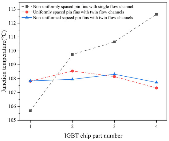
Figure 21.
Comparative analysis of IGBT chip junction temperatures for three optimized configurations.
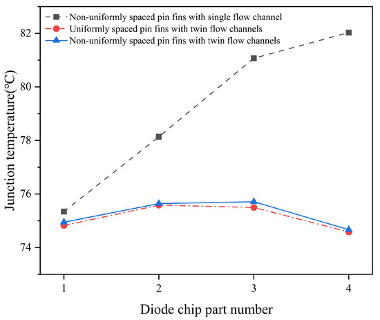
Figure 22.
Comparative analysis of diode chip junction temperatures for three optimized configurations.
As for diode junction temperatures, both the second and third schemes show identical trends: higher temperatures at central chips, lower at edge chips. The second scheme demonstrates an extremely marginal reduction in temperatures versus the third scheme (≈0.1 °C difference). The temperature uniformity is nearly identical between both schemes. Therefore, the diode thermal performance is statistically equivalent for both schemes.
The dual-flow-channel with non-uniform pin fins (third) scheme achieves optimal module junction temperatures but incurs higher pressure drops than the second scheme (1927 Pa vs. 1793 Pa). However, its significantly enhanced IGBT temperature uniformity fully offsets this minor disadvantage in pressure drop.
4. Conclusions
This study investigates the power loss and junction temperature of power devices in high-power-density motor controllers using finite element simulation software. The primary research focuses on three aspects: junction temperature performance of IGBT modules equipped with variably spaced pin fins under different operating conditions; effects of the coolant inlet velocity and temperature on the IGBT module junction temperatures; and pin-fin optimization for enhancing junction temperature uniformity of IGBT module chips. The key conclusions are summarized below:
- (1)
- The 2 mm spaced pin fins demonstrate superior thermal performance in IGBT modules: they achieve lower chip junction temperatures across three operating conditions and enhanced junction temperature uniformity.
- (2)
- The coolant inlet velocity exhibits a positive correlation with module junction temperature reduction and uniformity improvement. However, the benefits follow a trend of diminishing marginal returns with increasing velocity, coupled with a sharp increase in the pressure drop that requires critical consideration. Thus, it is necessary to select a moderate inlet velocity for multi-objective balance.
- (3)
- The coolant inlet temperature shows an inverse relationship with module junction temperatures and uniformity, following a linear functional trend within the simulated temperature range. Excessively low temperatures raise concerns regarding system stability and power consumption, so it is also essential to select a balanced temperature accounting for competing factors.
- (4)
- Among the three optimization schemes, the dual-flow-channel with non-uniformly spaced pin fins scheme delivers optimal performance: it is the most effective in reducing chip junction temperatures and significantly enhances junction temperature uniformity.
However, it cannot be overlooked that this study omitted the encapsulant of the IGBT module, which may influence the accuracy of the junction temperature estimations presented herein. We will refine the model in subsequent research and perform corresponding experimental validations to address this aspect.
Author Contributions
Model establishment, C.W.; software, C.W. and Y.S.; formal analysis, C.W. and F.W.; investigation, C.W., F.W. and Y.S.; writing—original draft, C.W. All authors have read and agreed to the published version of the manuscript.
Funding
This research received no external funding. This research was supported by the Key project of Chongqing Natural Science Foundation Innovation and Development Joint Fund (CSTB2024NSCQ-LZX0158) and Chongqing technology innovation and application demonstration project (CSTB2022TIAD-DEX0015).
Institutional Review Board Statement
Not applicable.
Informed Consent Statement
Not applicable.
Data Availability Statement
The data presented in this study are available upon request from the corresponding author.
Conflicts of Interest
The authors declare no conflicts of interest.
References
- Tian, P.; Mao, B.; Tong, R.; Zhang, H.; Zhou, Q. Analysis of carbon emission levels and intensity of our country’s transportation industry and different modes of transportation. Clim. Chang. Res. 2023, 19, 347–356. [Google Scholar]
- Oh, H.; Han, B.; McCluskey, P.; Han, C.; Youn, B.D. Physics-of-failure, condition monitoring, and prognostics of insulated gate bipolar transistor modules: A review. IEEE Trans. Power Electron. 2015, 30, 2413–2426. [Google Scholar] [CrossRef]
- Kraus, A.D.; Bar-Cohen, A. Design and Analysis of Heat Sinks; Wiley: New York, NY, USA, 1995. [Google Scholar]
- Abramushkina, E.; Zhaksylyk, A.; Geury, T.; El Baghdadi, M.; Hegazy, O. A Thorough Review of Cooling Concepts and Thermal Management Techniques for Automotive WBG Inverters: Topology, Technology and Integration Level. Energies 2021, 14, 4981. [Google Scholar] [CrossRef]
- Uhlemann, A.; Herbrandt, A. A New Base Plate Concept on the Basis of Aluminium-Copper Clad Materials. In Proceedings of the PCIM Europe 2012 Conference, Nuremberg, Germany, 8–10 May 2012; pp. 680–685. [Google Scholar]
- Silk, E.A.; Kim, J.; Kiger, K. Investigation of enhanced surface spray cooling. In Proceedings of the IMECE2004: ASME International Mechanical Engineering Congress, Anaheim, CA, USA, 13–19 November 2004; pp. 685–690. [Google Scholar]
- Rohsenow, W.M.; Hartnett, J.P.; Cho, Y.I. Handbook of Heat Transfer; McGraw-Hill: New York, NY, USA, 1998. [Google Scholar]
- Sun, Z.Y. Research on Junction Temperature Estimation Method of IGBT Module Based on Multiple Models. Master’s Thesis, Hefei University of Technology, Hefei, China, 2019. [Google Scholar]
- Zhang, R. Simulation Study on Heat Dissipation Performance and Thermal Stress of IGBT Module Package Based on Finite Element Method. Master’s Thesis, Chongqing University: Chongqing, China, 2015. [Google Scholar]
- Sun, H.F.; Wang, Y.N. IGBT thermal model simulation based on finite element method. Electr. Power Sci. Eng. 2019, 35, 15–22. [Google Scholar]
- He, M.G.; Xu, Z.L.; Xie, W.Y.; Ge, X.L.; Wang, W.J. The thermal network junction temperature calculation considers the aging of the bond wire and the solder layer of the IGBT module chip. Railw. Locomot. Car 2024, 44, 28–35. [Google Scholar]
- Górecki, K.; Górecki, P. SPICE-Aided Nonlinear Electrothermal Modeling of an IGBT Module. Electronics 2023, 12, 4588. [Google Scholar] [CrossRef]
- Kwon, J.; Han, C.; Lee, S.; Baek, C.; Kim, Y. Thermal and energy performance characteristics of spiral-wing pin-fin heatsinks for liquid cooling of electronic devices in electric vehicles. Int. Commun. Heat Mass Transf. 2024, 156, 107705. [Google Scholar] [CrossRef]
- Gu, W.; Zhang, X.; Zhang, B.; Lin, Q.; Jia, Z.; Liu, F.; Qiu, J.; He, Y.; Li, Q. Experimental and numerical investigation on turbulent convection enhancement in minichannel heat sink with staggered V-shaped pin fins. Numer. Heat Transf. Part A Appl. 2024, 1–24. [Google Scholar] [CrossRef]
- Yahyaee, A.; Bahman, A.S.; Blaabjer, F. A Modification of Offset Strip Fin Heatsink with High-Performance Cooling for IGBT Modules. Appl. Sci. 2020, 10, 1112. [Google Scholar] [CrossRef]
- Suresh, A.; Jinesh, N.; Antony, J.K.; Issac, A. Design of Liquid Cooled Pin–Fin Heat Sink for High Voltage Electric Vehicle. In Fluid Mechanics and Fluid Power; Singh, K.M., Dutta, S., Subudhi, S., Singh, N.K., Eds.; Lecture Notes in Mechanical Engineering; Springer: Singapore, 2022; Volume 1. [Google Scholar]
- Fan, F.; Fan, X.; Zhang, L. Simulation and Optimization of Water-cooled Radiator with Pin-fins for IGBT Module. In Proceedings of the 2023 Panda Forum on Power and Energy (PandaFPE), Chengdu, China, 27–30 April 2023; pp. 2215–2220. [Google Scholar]
- Cho, S.; Pyun, S.; Yoon, S.W. Analysis model for thermal resistance of double-sided cooling power module with pin–fin heat sink used in xEVs. J. Power Electron. 2023, 23, 1880–1887. [Google Scholar] [CrossRef]
- Chen, M.; Chen, Y.; Gao, B.; Lai, W.; Huang, T.; Xu, S.Y. Lifetime evaluation of IGBT module considering fatigue accumulation of solder layers. Proc. CSEE 2018, 38, 6053–6061. [Google Scholar]
- Ren, Z.Y. Research on Fatigue Failure Analysis and Junction Temperature Prediction of IGBT Module. Master’s Thesis, Dalian University of Technology, Dalian, China, 2022. [Google Scholar]
- Dou, X. Research on Flow Heat Transfer Analysis and Cooling Strategy of Liquid Cold Plate of High-Power Density IGBT Module. Master’s Thesis, Zhejiang University, Hangzhou, China, 2023. [Google Scholar]
Disclaimer/Publisher’s Note: The statements, opinions and data contained in all publications are solely those of the individual author(s) and contributor(s) and not of MDPI and/or the editor(s). MDPI and/or the editor(s) disclaim responsibility for any injury to people or property resulting from any ideas, methods, instructions or products referred to in the content. |
© 2025 by the authors. Licensee MDPI, Basel, Switzerland. This article is an open access article distributed under the terms and conditions of the Creative Commons Attribution (CC BY) license (https://creativecommons.org/licenses/by/4.0/).