Author Contributions
Conceptualization, X.Y. and B.S.; methodology, B.W., X.Y. and B.S.; validation, B.W. and K.S.; formal analysis, B.W. and K.S.; investigation, B.W. and K.S.; resources, X.Y. and B.S.; data curation, B.W.; writing—original draft preparation, B.W.; writing—review and editing, B.W., K.S. and X.Y.; visualization, B.W.; supervision, X.Y. and B.S.; project administration, B.W., K.S. and X.Y.; funding acquisition, X.Y. All authors have read and agreed to the published version of the manuscript.
Figure 1.
Profile of NPU-LS 0515 airfoil.
Figure 1.
Profile of NPU-LS 0515 airfoil.
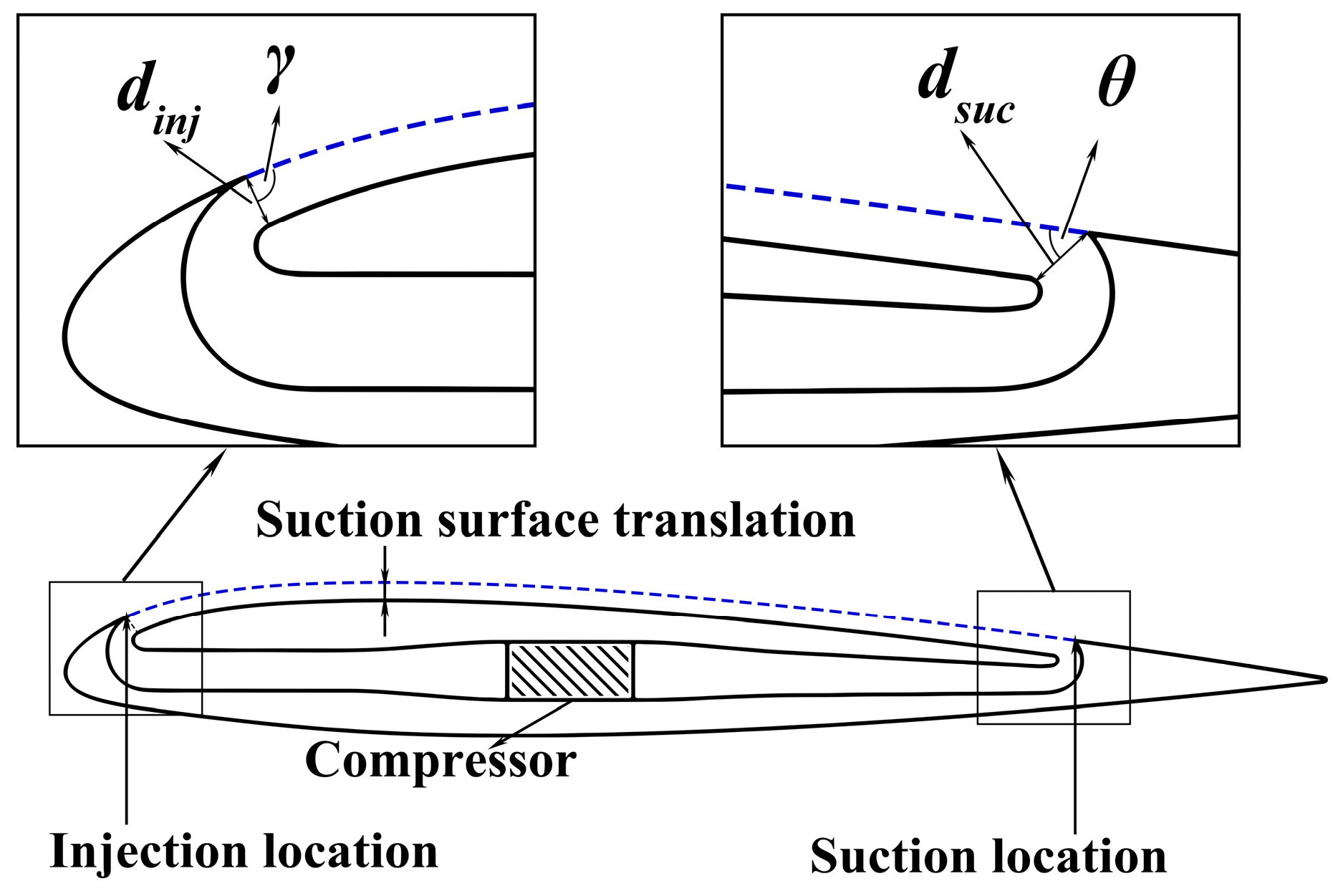
Figure 2.
Schematic of CFJ geometric parameters.
Figure 2.
Schematic of CFJ geometric parameters.
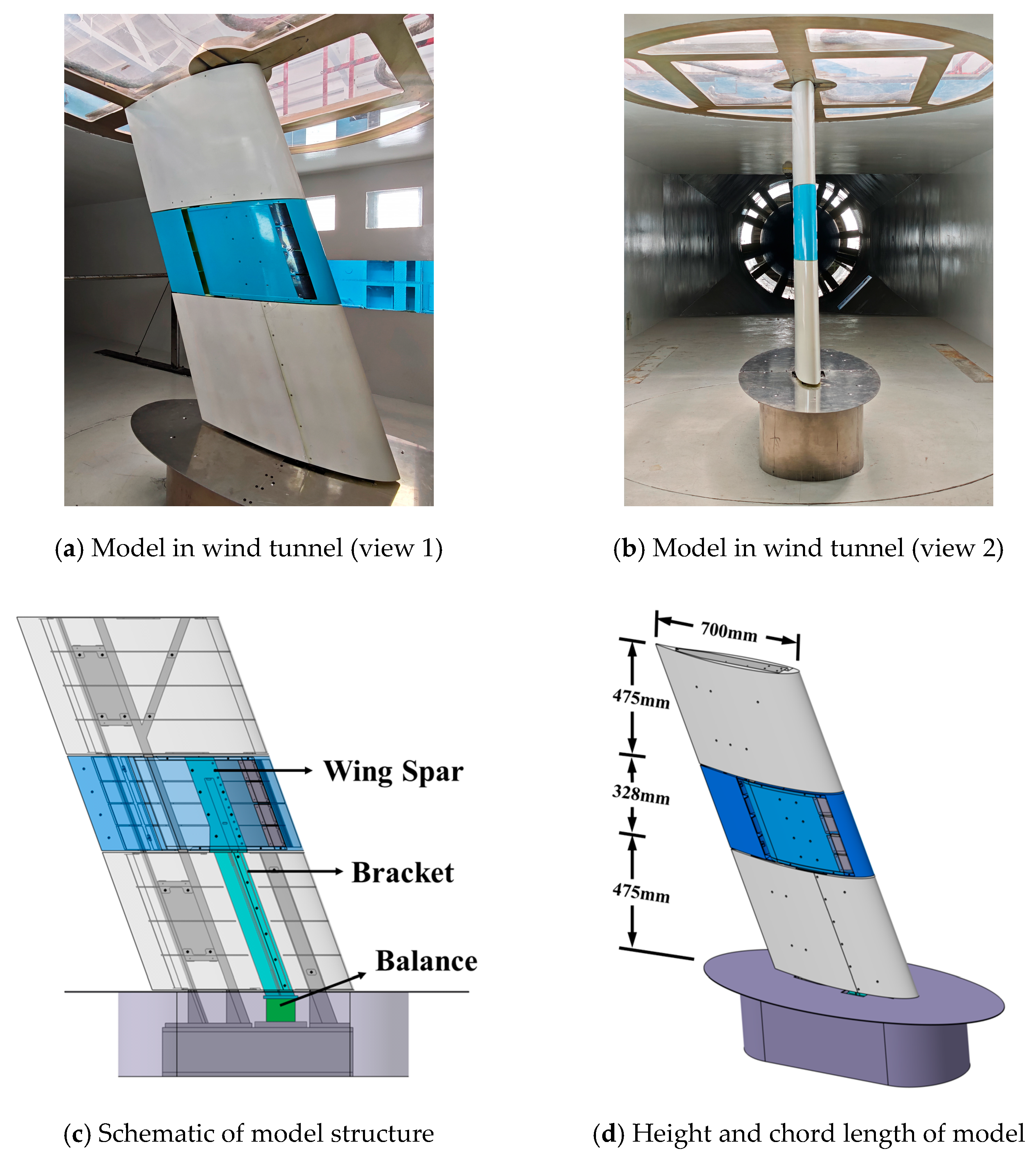
Figure 3.
Schematic of the CFJ swept wing model for wind tunnel experiments.
Figure 3.
Schematic of the CFJ swept wing model for wind tunnel experiments.
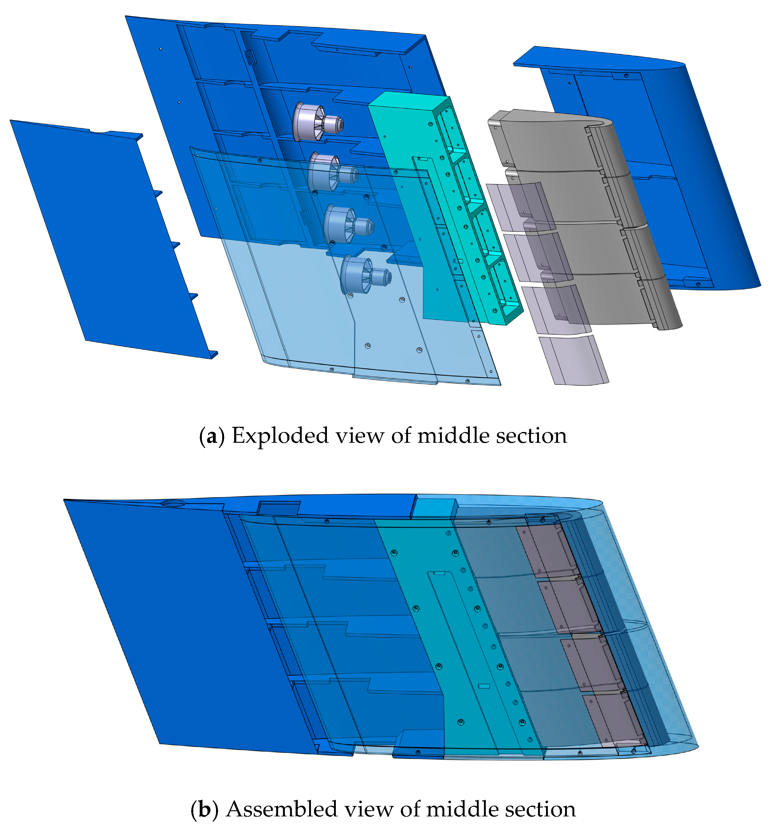
Figure 4.
Schematic of the middle section of the CFJ swept wing model.
Figure 4.
Schematic of the middle section of the CFJ swept wing model.
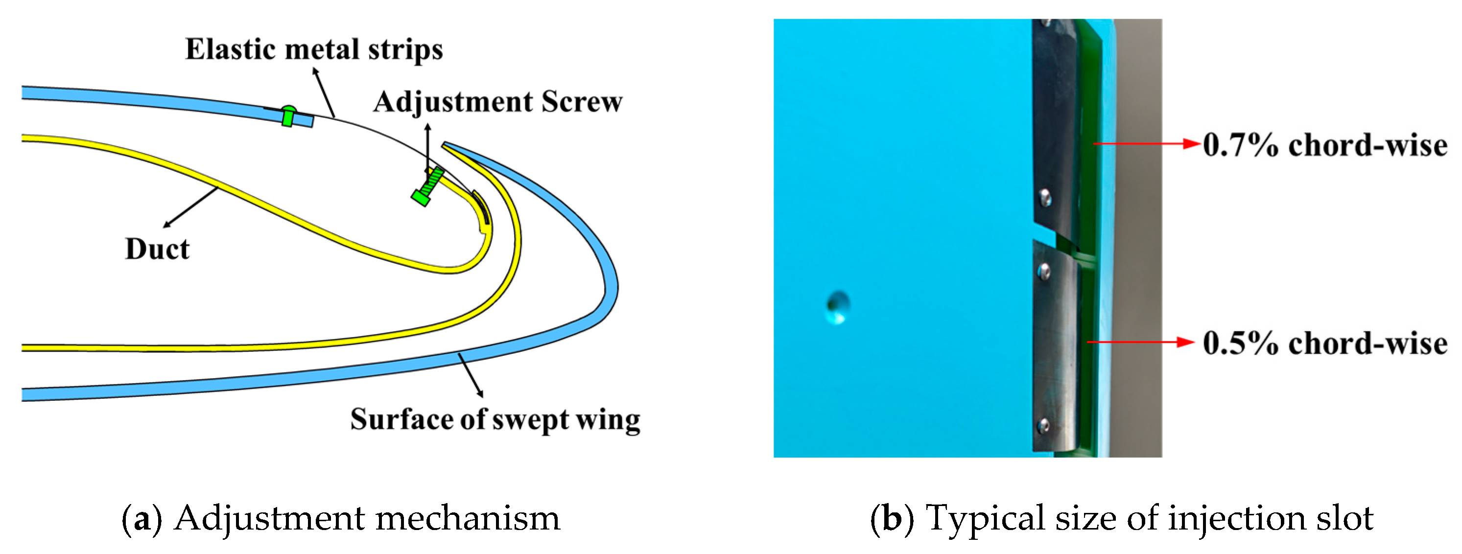
Figure 5.
Adjustment mechanism for the injection slot size and comparison of two typical injection slot sizes.
Figure 5.
Adjustment mechanism for the injection slot size and comparison of two typical injection slot sizes.
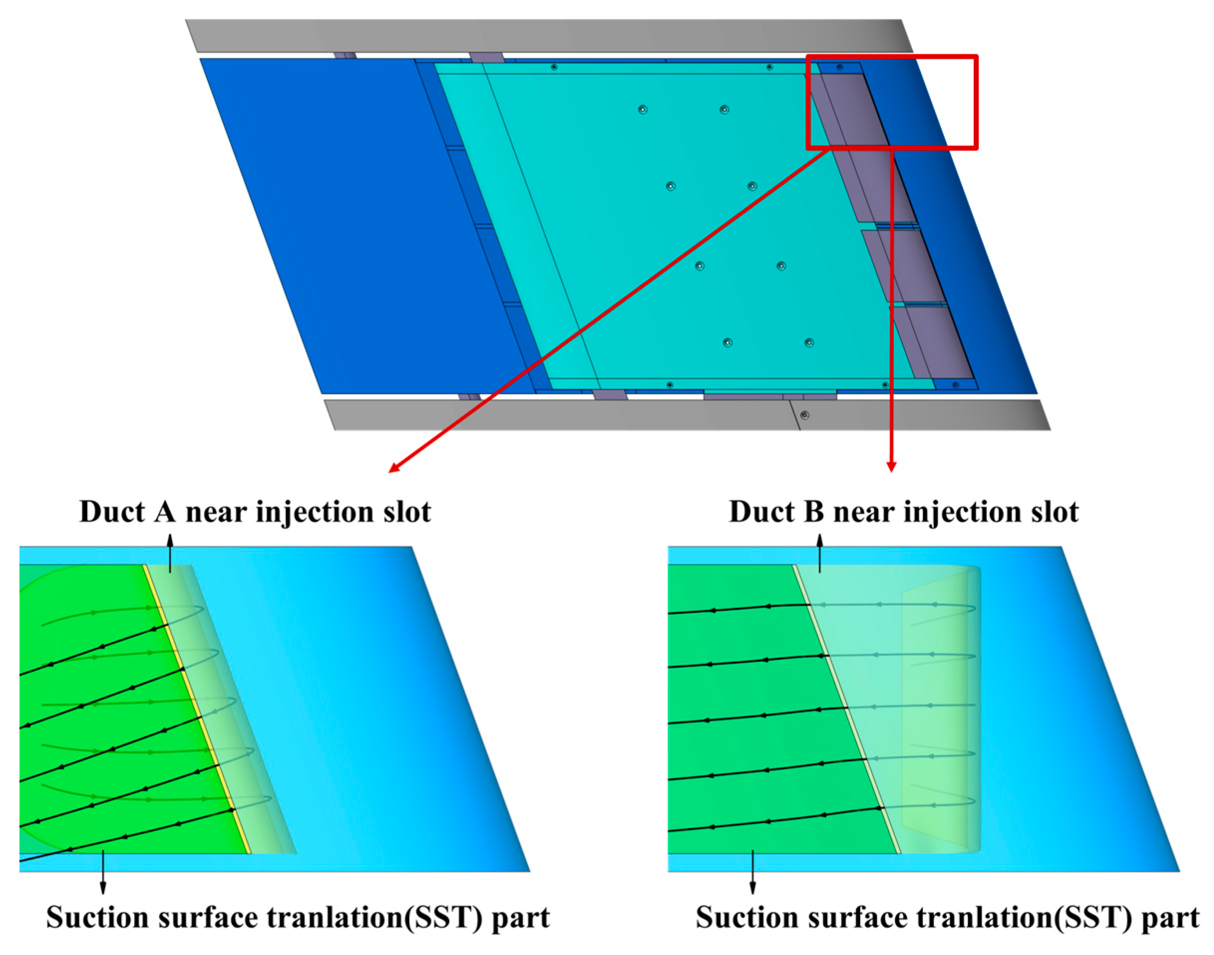
Figure 6.
Geometric comparison at turning section of the two ducts.
Figure 6.
Geometric comparison at turning section of the two ducts.
Figure 7.
Jet direction at the outlet of the two ducts.
Figure 7.
Jet direction at the outlet of the two ducts.
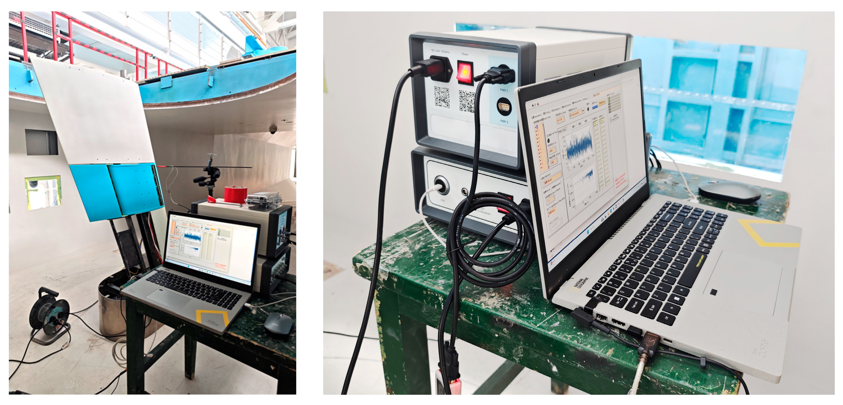
Figure 8.
Force balance and VXI data acquisition system.
Figure 8.
Force balance and VXI data acquisition system.
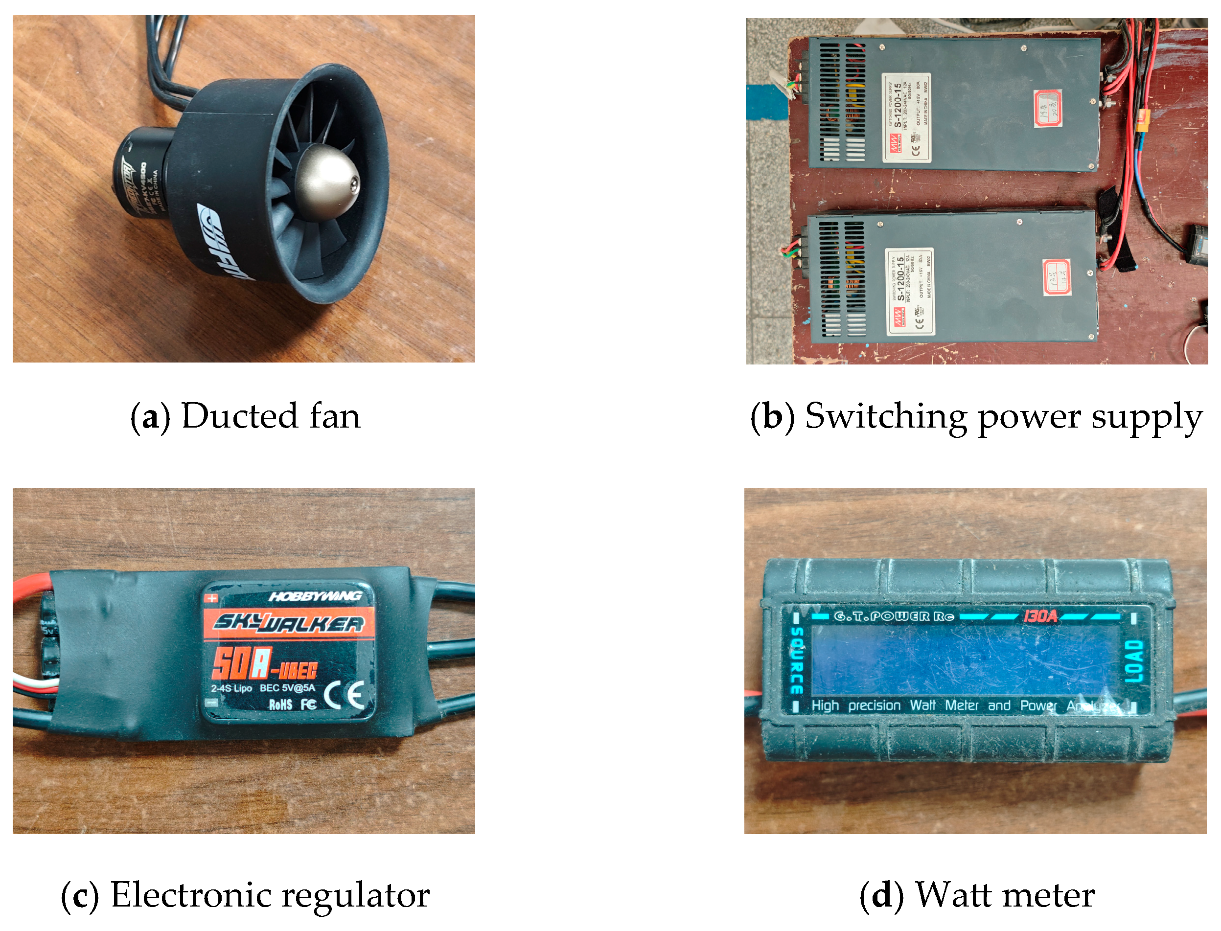
Figure 9.
Ducted fans and associated control equipment.
Figure 9.
Ducted fans and associated control equipment.
Figure 10.
Jet velocity measurement test.
Figure 10.
Jet velocity measurement test.
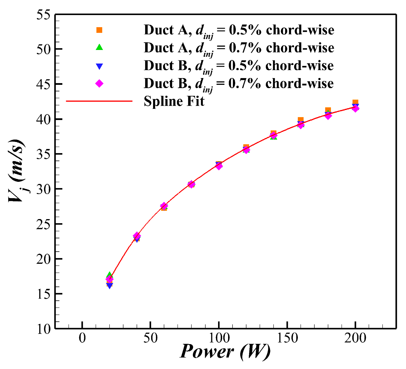
Figure 11.
Relationship between jet velocity and ducted fan power at the injection slot.
Figure 11.
Relationship between jet velocity and ducted fan power at the injection slot.
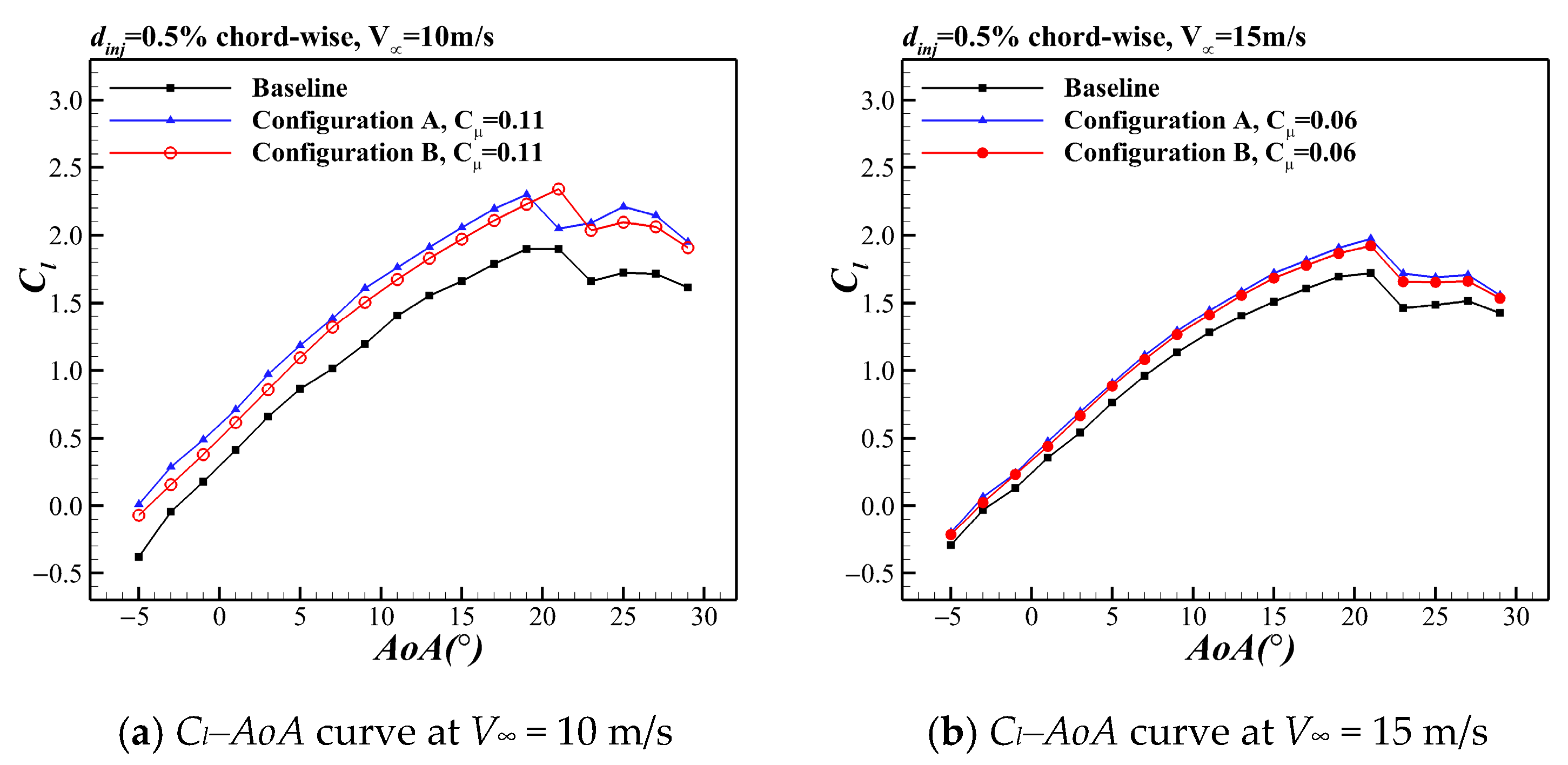
Figure 12.
Comparison of lift coefficient characteristics between the baseline and CFJ swept wing configurations (AoA from −5° to 29°).
Figure 12.
Comparison of lift coefficient characteristics between the baseline and CFJ swept wing configurations (AoA from −5° to 29°).
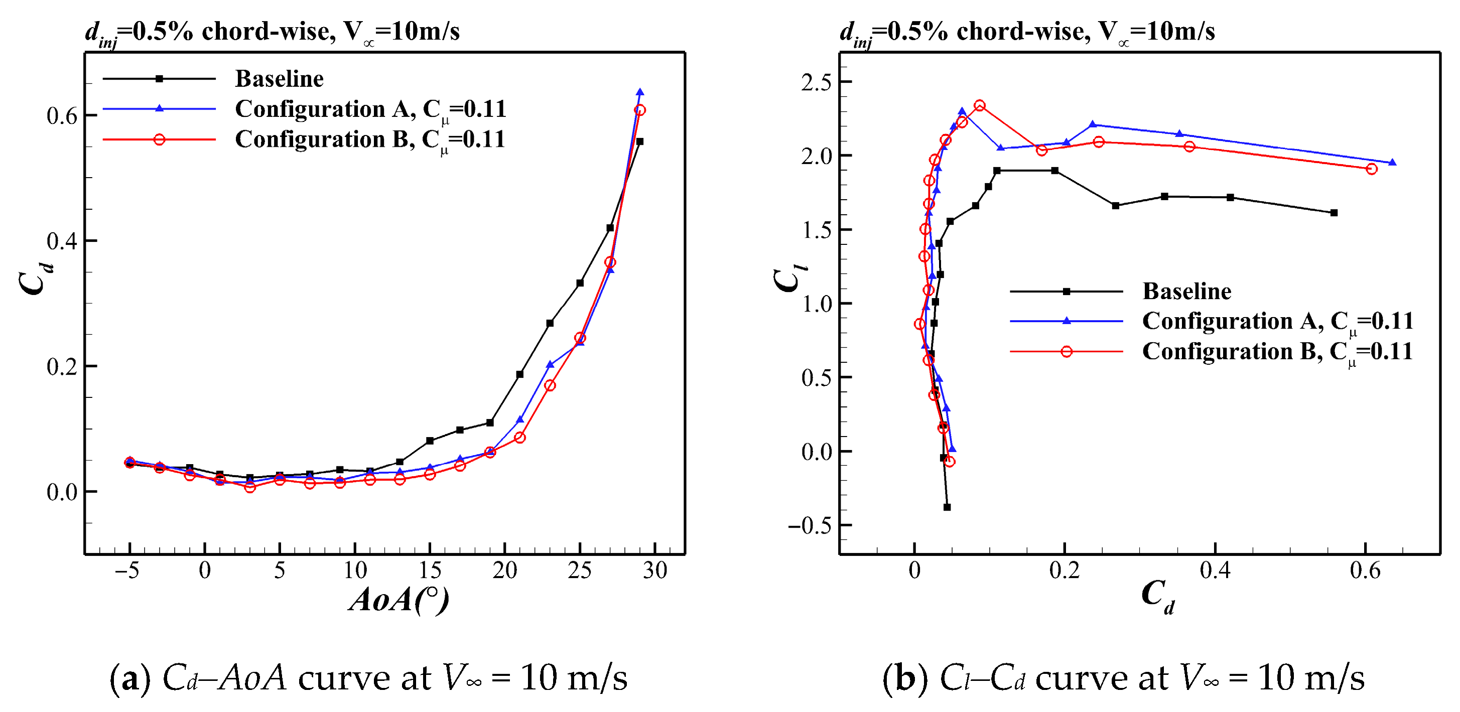
Figure 13.
Comparison of aerodynamic characteristics of CFJ swept wings equipped with two different ducts (AoA from −5° to 29°).
Figure 13.
Comparison of aerodynamic characteristics of CFJ swept wings equipped with two different ducts (AoA from −5° to 29°).
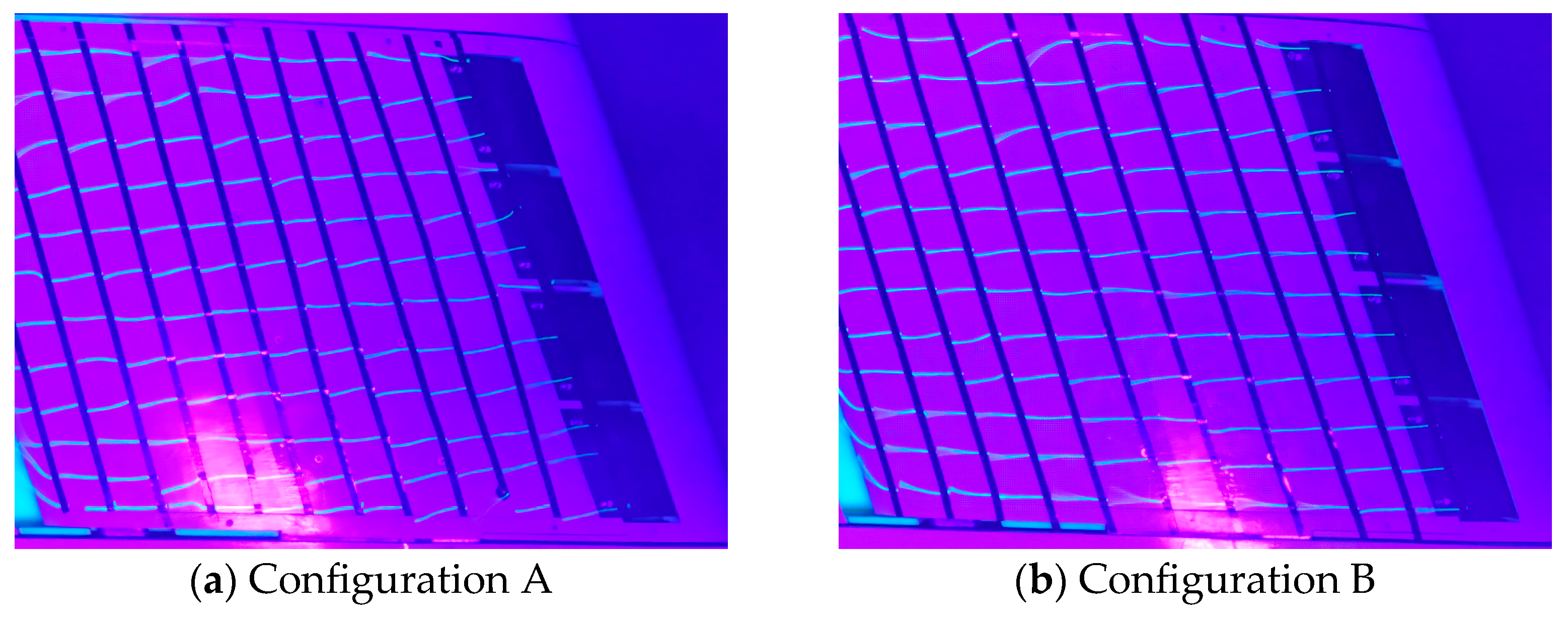
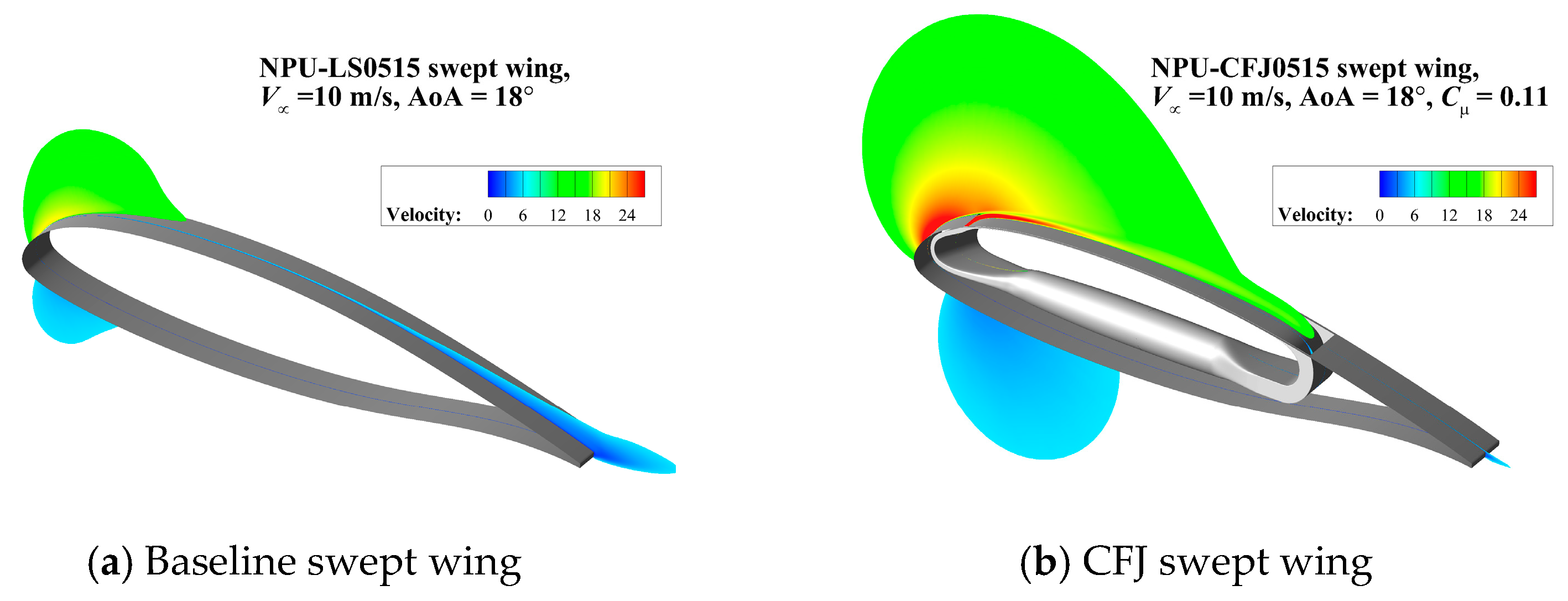
Figure 14.
Comparison of flow field visualization results between Configurations A and B of the CFJ swept wing.
Figure 14.
Comparison of flow field visualization results between Configurations A and B of the CFJ swept wing.
Figure 15.
Comparison of velocity contours of the slice in the chord-wise direction between the baseline and the CFJ swept wing.
Figure 15.
Comparison of velocity contours of the slice in the chord-wise direction between the baseline and the CFJ swept wing.
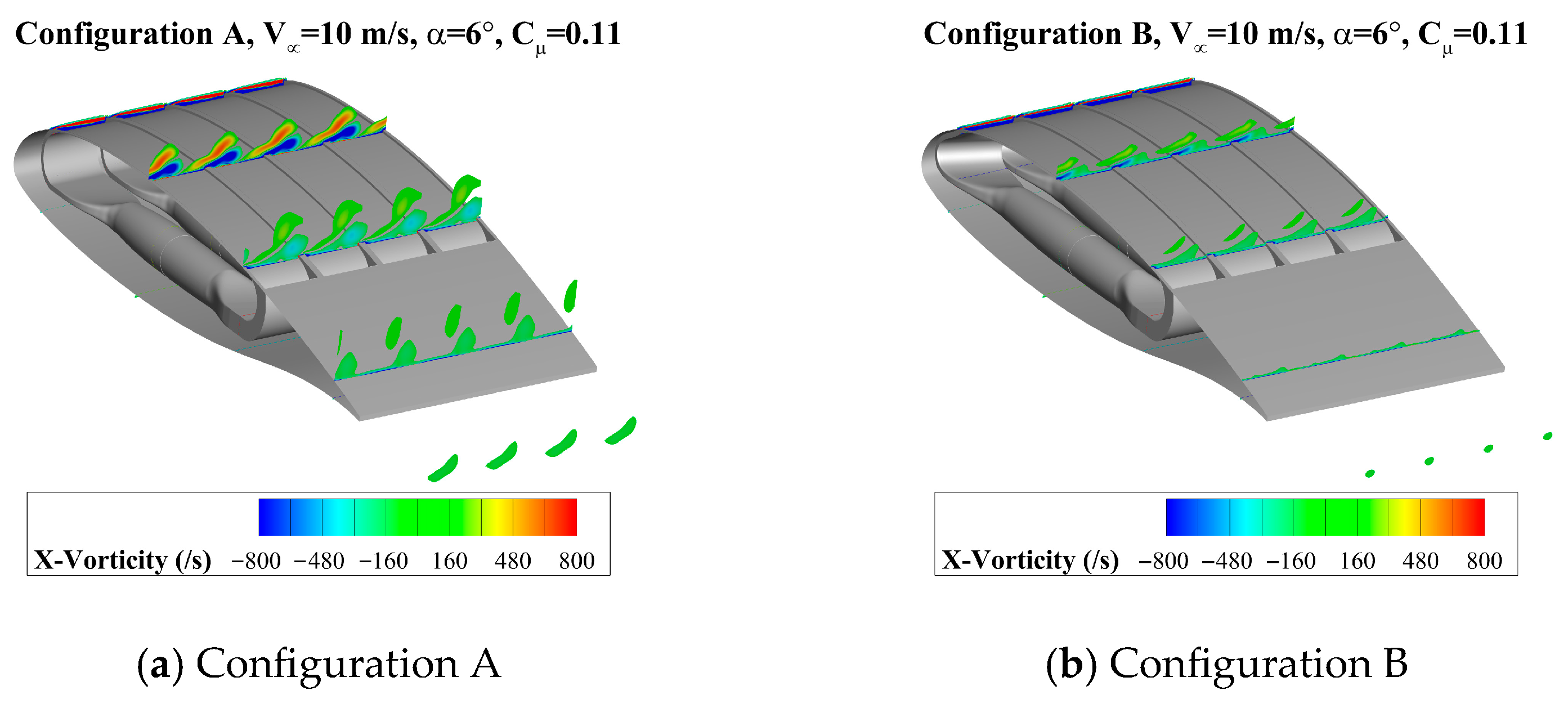
Figure 16.
Comparison of vorticity contours in the flow direction component between Configurations A and B of the CFJ swept wing.
Figure 16.
Comparison of vorticity contours in the flow direction component between Configurations A and B of the CFJ swept wing.
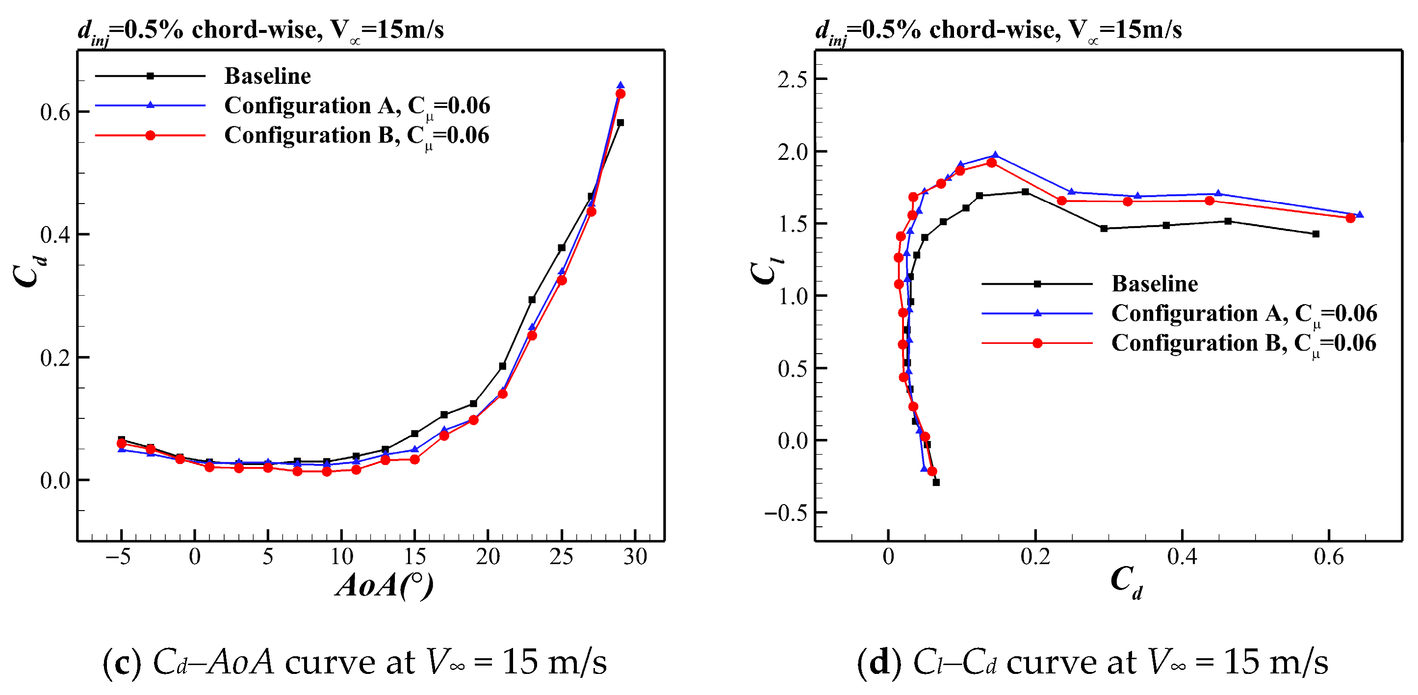
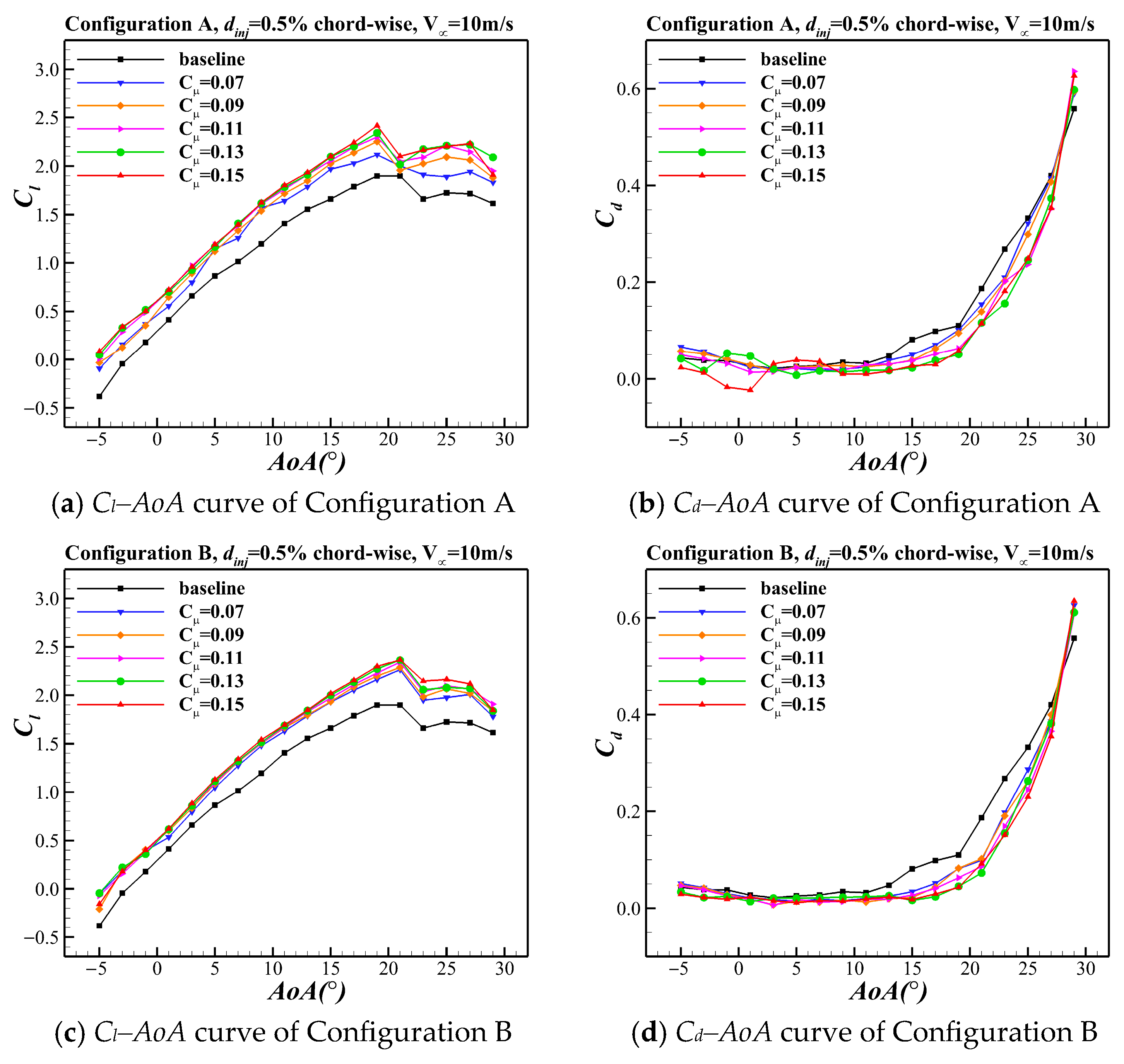
Figure 17.
Comparison of aerodynamic force characteristics of two CFJ swept wing configurations under different jet momentum coefficients (AoA from −5° to 29°).
Figure 17.
Comparison of aerodynamic force characteristics of two CFJ swept wing configurations under different jet momentum coefficients (AoA from −5° to 29°).
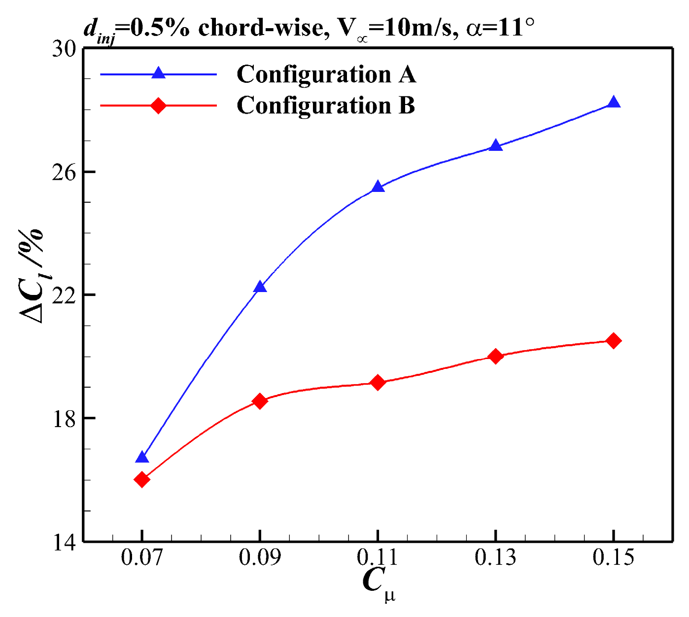
Figure 18.
Comparison of lift coefficient increment versus Cµ for the two CFJ swept wing configurations (V∞ = 10 m/s and α = 11°).
Figure 18.
Comparison of lift coefficient increment versus Cµ for the two CFJ swept wing configurations (V∞ = 10 m/s and α = 11°).
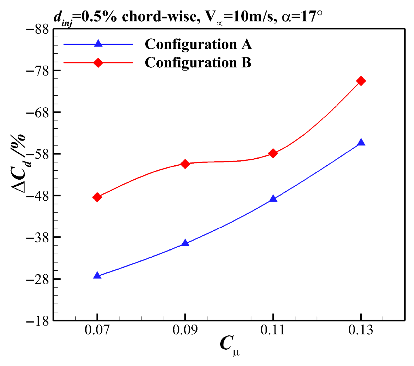
Figure 19.
Comparison of drag coefficient reduction versus Cµ for the two CFJ swept wing configurations (V∞ = 10 m/s and α = 17°).
Figure 19.
Comparison of drag coefficient reduction versus Cµ for the two CFJ swept wing configurations (V∞ = 10 m/s and α = 17°).
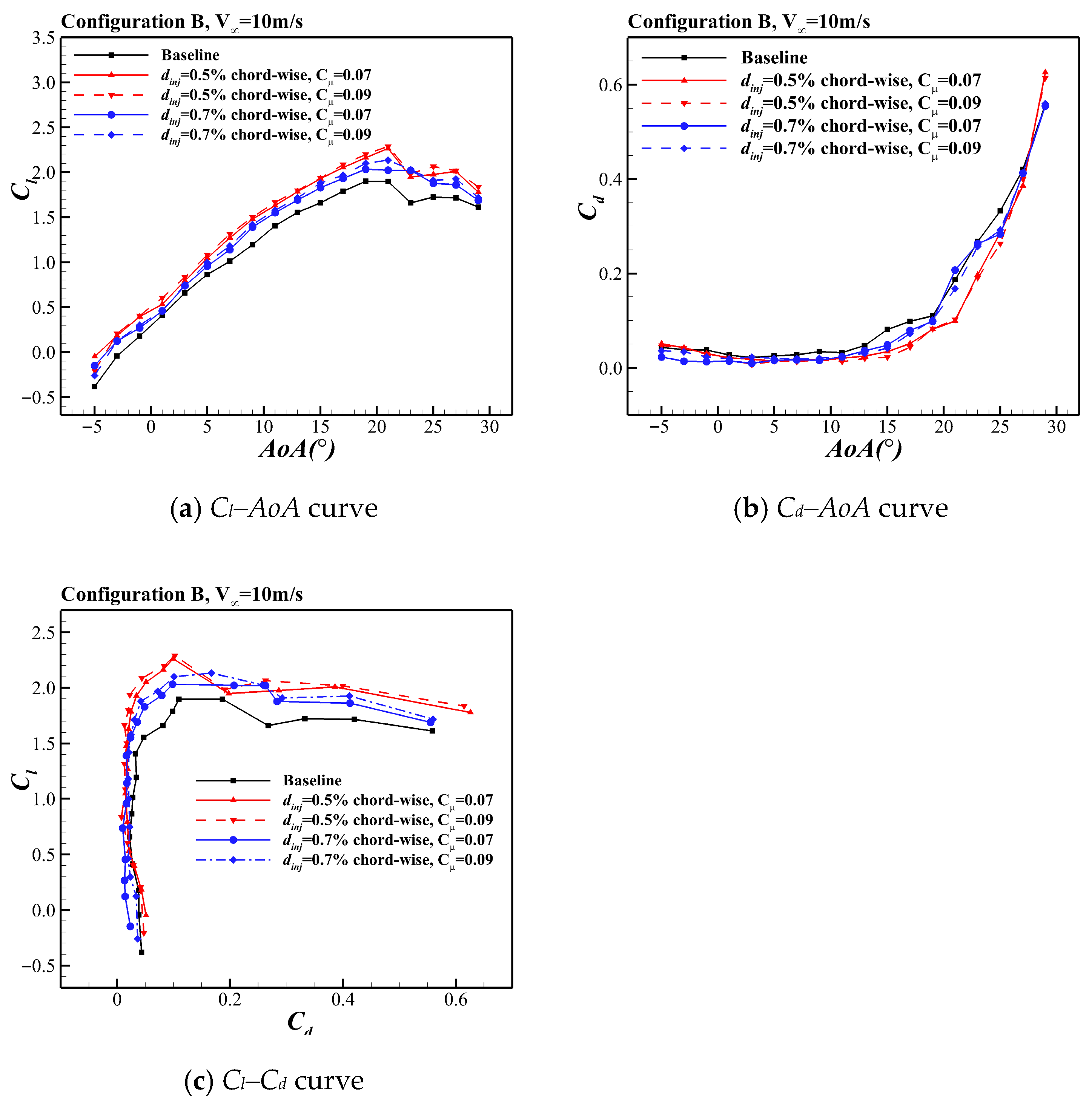
Figure 20.
Comparison of aerodynamic forces on the CFJ swept wing for different injection slot sizes (AoA from −5° to 29°).
Figure 20.
Comparison of aerodynamic forces on the CFJ swept wing for different injection slot sizes (AoA from −5° to 29°).
Table 1.
Key CFJ geometric parameters of the NPU-CFJ 0515 airfoil.
Table 1.
Key CFJ geometric parameters of the NPU-CFJ 0515 airfoil.
| Geometric Parameters | Detail Value |
|---|
| Injection slot location | 8% chord-wise |
| Injection slot angle γ | 75° |
| Suction slot location | 70% chord-wise |
| 2.5% chord-wise |
| Suction slot angle θ | 45° |
| Suction surface translation | 0.3% chord-wise |
Table 2.
Comparison between measured and fitted jet velocities at different ducted fan power levels.
Table 2.
Comparison between measured and fitted jet velocities at different ducted fan power levels.
| Power of Ducted Fan (W) | Cubic Spline Fitting (m/s) | Hot-Wire Velocity Measurement (m/s) |
|---|
| 30 | 20.48 | 20.76 |
| 70 | 29.30 | 28.97 |
| 110 | 34.71 | 34.89 |
| 150 | 38.56 | 38.20 |
Table 3.
Correspondence between jet momentum coefficient, jet velocity, and ducted fan power at the injection slot (V∞ = 10 m/s).
Table 3.
Correspondence between jet momentum coefficient, jet velocity, and ducted fan power at the injection slot (V∞ = 10 m/s).
| Jet Momentum Coefficient | Dinj = 0.5% Chord-Wise | dinj = 0.7% Chord-Wise |
|---|
| Required Jet Velocity (m/s) | Ducted Fan Power (W) | Required Jet Velocity (m/s) | Ducted Fan Power (W) |
|---|
| 0.07 | 26.46 | 53.9 | 22.36 | 36.5 |
| 0.09 | 30.00 | 74.5 | 25.35 | 48.7 |
| 0.11 | 33.17 | 97.0 | 28.03 | 61.2 |
| 0.13 | 36.06 | 122.7 | 30.47 | 73.7 |
| 0.15 | 38.73 | 152.2 | 32.73 | 86.2 |
Table 4.
Correspondence between jet momentum coefficient, jet velocity, and ducted fan power at the injection slot (V∞ = 15 m/s).
Table 4.
Correspondence between jet momentum coefficient, jet velocity, and ducted fan power at the injection slot (V∞ = 15 m/s).
| Jet Momentum Coefficient | dinj = 0.5% Chord-Wise | dinj = 0.7% Chord-Wise |
|---|
| Required Jet Velocity (m/s) | Ducted Fan Power (W) | Required Jet Velocity (m/s) | Ducted Fan Power (W) |
|---|
| 0.05 | 33.54 | 100.1 | 28.35 | 64.2 |
| 0.06 | 36.74 | 129.6 | 31.05 | 81.6 |
Table 5.
Comparison of lift coefficient enhancement at typical AoAs for the two CFJ swept wing configurations (V∞ = 10 m/s and Cµ = 0.11).
Table 5.
Comparison of lift coefficient enhancement at typical AoAs for the two CFJ swept wing configurations (V∞ = 10 m/s and Cµ = 0.11).
| Configuration | | |
|---|
| AoA = 5° | AoA = 15° | AoA = 5° | AoA = 15° |
|---|
| Baseline swept wing | 0.865 | 1.662 | - | - |
| CFJ swept wing (Configuration A) | 1.185 | 2.056 | 37.0% | 23.7% |
| CFJ swept wing (Configuration B) | 1.093 | 1.972 | 26.4% | 18.7% |
Table 6.
Comparison of lift coefficient enhancement at typical AoAs for the two CFJ swept wing configurations (V∞ = 15 m/s and Cµ = 0.06).
Table 6.
Comparison of lift coefficient enhancement at typical AoAs for the two CFJ swept wing configurations (V∞ = 15 m/s and Cµ = 0.06).
| Configuration | | |
|---|
| AoA = 5° | AoA = 15° | AoA = 5° | AoA = 15° |
|---|
| Baseline swept wing | 0.763 | 1.511 | - | - |
| CFJ swept wing (Configuration A) | 0.905 | 1.722 | 18.5% | 14.0% |
| CFJ swept wing (Configuration B) | 0.884 | 1.685 | 15.9% | 11.5% |
Table 7.
Comparison of the effects of two duct configurations on drag reduction at a typical AoA for CFJ swept wings (V∞ = 10 m/s, α = 15°, and Cµ = 0.11).
Table 7.
Comparison of the effects of two duct configurations on drag reduction at a typical AoA for CFJ swept wings (V∞ = 10 m/s, α = 15°, and Cµ = 0.11).
| Configuration | | | | |
|---|
| Baseline swept wing | 0.0815 | - | 20.4 | - |
| CFJ swept wing (Configuration A) | 0.0383 | −53.0% | 53.9 | 163.3% |
| CFJ swept wing (Configuration B) | 0.0270 | −66.9% | 73.0 | 258.2% |
Table 8.
Comparison of increments in maximum lift coefficient for the CFJ swept wing for different injection slot sizes.
Table 8.
Comparison of increments in maximum lift coefficient for the CFJ swept wing for different injection slot sizes.
| Injection Size | Cµ = 0.07 | Cµ = 0.09 |
|---|
| | | |
|---|
| 0.5% chord-wise | 2.262 | 19.2% | 2.287 | 20.5% |
| 0.7% chord-wise | 2.033 | 7.1% | 2.134 | 11.4% |

