Article

Electromagnetic and NVH Characteristic Analysis of Eccentric State for Surface-Mounted Permanent Magnet Synchronous Generators in Wave Power Applications

by
Woo-Sung Jung
1,
Yeon-Su Kim
1,
Yeon-Tae Choi
1,
Kyung-Hun Shin
2,* and
Jang-Young Choi
1,*
1
Department of Electrical Engineering, Chungnam National University, Daejeon 34134, Republic of Korea
2
Department of Electrical Engineering, Changwon National University, Changwon 51140, Republic of Korea
*
Authors to whom correspondence should be addressed.
Appl. Sci. 2025, 15(17), 9697; https://doi.org/10.3390/app15179697
Submission received: 11 August 2025 / Revised: 29 August 2025 / Accepted: 30 August 2025 / Published: 3 September 2025
(This article belongs to the Special Issue Nonlinear Dynamics and Vibration)

Abstract

Featured Application

This study analyzes the electromagnetic and mechanical characteristics of a permanent magnet synchronous generator (PMSG) for wave energy applications under rotor eccentricity. By evaluating the electromagnetic excitation and noise–vibration–harshness (NVH) behavior caused by eccentricity, the proposed approach provides practical insights to enhance both power quality and structural stability. These findings contribute to the design of efficient and low-noise marine generators suitable for long-term operation in harsh marine environments.

Abstract

This study investigates the electromagnetic and NVH characteristics of an outer-rotor surface-mounted permanent magnet synchronous generator (SPMSG) for wave energy applications, focusing on the effect of rotor eccentricity. To reflect potential fault due to manufacturing or assembly defects, a 0.5 mm rotor eccentricity was introduced in finite element method (FEM) simulations. The torque ripple waveform was analyzed using fast Fourier transform (FFT) to identify dominant harmonic components that generate unbalanced electromagnetic forces and induce structural vibration. These harmonic components were further examined under variable marine operating conditions to evaluate their impact on acoustic radiation and vibration responses. Based on the simulation and analysis results, a design-stage methodology is proposed for predicting vibration and noise by targeting critical harmonic excitations, providing practical insights for marine generator design and improving long-term operational reliability in wave energy systems.

1. Introduction

Recently, renewable energy sources have gained significant attention due to increasing concerns regarding resource depletion and environmental degradation. Among various technologies, power generation systems employing permanent magnet synchronous generators (PMSGs) are regarded as one of the most efficient solutions to mitigate global warming and reduce environmental impact. PMSGs generate electricity by utilizing the interaction between permanent magnets and electromagnetic fields, providing high efficiency and stable operation [1,2].
However, renewable energy systems are inherently subject to fluctuating environmental conditions, which often lead to unstable operating states and output variations. Such instability increases the likelihood of structural and performance issues in PMSGs [3]. In particular, outer-rotor surface-mounted PMSGs (SPMSGs) are more vulnerable to rotor eccentricity because the larger rotor radius amplifies both centrifugal and electromagnetic forces [4,5]. Rotor eccentricity distorts the magnetic flux distribution and reduces the uniformity of the electromagnetic field, resulting in voltage imbalance, increased cogging torque, elevated torque ripple, and higher harmonic content. These effects can further amplify noise and vibration, ultimately compromising mechanical integrity and acoustic performance.
To ensure the reliability and efficiency of wave energy conversion systems, it is therefore essential to systematically investigate the influence of rotor eccentricity on outer-rotor SPMSGs [6,7,8,9]. In this study, a comprehensive analysis of the electromagnetic and noise–vibration–harshness (NVH) characteristics of an outer-rotor SPMSG under rotor eccentricity is conducted. Torque ripple, fast Fourier transform (FFT)-based excitation force distribution, and dominant harmonic components are evaluated, and the mechanical responses obtained from two- and three-dimensional finite element method (FEM) simulations are validated through experimental measurements. By comprehensively assessing the electromagnetic and mechanical impacts of rotor eccentricity, this study provides practical guidelines for the design and diagnosis of marine PMSGs, aiming to enhance both energy output stability and long-term structural reliability under harsh operating conditions.

2. Analysis Model of the Outer Rotor SPMSG with Rotor Eccentricity

Figure 1 shows the 2D geometry of the PMSG used in the finite element analysis. Figure 1a is the model in the steady state, and Figure 1b is the model in the eccentric state where the rotor is tilted to one side. Table 1 shows the detailed design specifications of the PMSG evaluated in this study. When the rotor eccentricity occurs, an imbalance of the air gap with the stator occurs, which can lead to a deviation in the flux linkage and a deviation in the induced voltage. The same specifications were applied to both the steady-state and eccentric models to ensure a fair comparison.

3. Electromagnetic Analysis

The electromagnetic analysis of the outer-rotor SPMSG was conducted to evaluate the influence of rotor eccentricity on electrical and mechanical performance. Mechanical vibration sources such as rotor eccentricity and structural imbalance modify the machine’s electromagnetic behavior, generating unbalanced electromagnetic forces that introduce non-uniform load distributions [10,11]. These vibrations can ultimately precipitate mechanical failure and degrade overall performance. Accordingly, a detailed analysis of the electromagnetic characteristics is essential for identifying the mechanisms that give rise to vibration [12]. In this section, the analysis focuses on the back-EMF, the torque ripple and its harmonic components, and the electromagnetic force distribution derived from FEM simulations and frequency-domain evaluation.

3.1. Back-EMF Characteristics

The total harmonic distortion (THD) of the back-EMF has a direct impact on torque characteristics. A highly distorted back-EMF waveform indicates the presence of specific harmonic components, which can induce torque ripple and amplify electromagnetic pulsations, ultimately leading to increased vibration and noise. Therefore, detailed analysis of back-EMF characteristics is essential [13,14].
In this study, the back-EMF waveform was analyzed using FFT to quantify its THD. The effects of rotor eccentricity were investigated, particularly focusing on how the magnitude and waveform of the back-EMF differ among phases under eccentric conditions. Specific harmonic orders that arise due to eccentricity were identified and analyzed for their contribution to vibration and noise.
This study quantitatively establishes rotor eccentricity tolerance levels that can be allowed during manufacturing and assembly. The results also demonstrate that applying these limits contributes to the reduction in torque ripple and improvements in NVH performance, thereby guiding the optimal design of permanent magnet machines.

3.2. Torque Characteristics with FFT-Based Harmonic Components

For PMSG, if the THD of the back-EMF is reduced, the harmonic current delivered to the load is reduced, which reduces losses and increases efficiency. In addition, THD is a very important characteristic in a generator because it affects torque ripple. Therefore, it is recommended that PM generators have a sinusoidal voltage. The equation below is the phase back-EMF and current equation [15]:
T = 3 2 K 1 I 1 + 1 2 I 1 n = 3 , o d d K n [ 1 + 2 cos { ( n 1 ) 2 π 3 } ] × cos ( n 1 ) p ω r t + 1 2 I 1 n = 3 , o d d K n [ 1 + 2 cos { ( n + 1 ) 2 π 3 } ] × cos ( n + 1 ) p ω r t
Here, K is the counter-electromotive force constant, and I is the amplitude of the fundamental component of the phase current [15]. Since the electromagnetic torque is derived through Equations (1) and (2) above, the influence of voltage and current is significant.
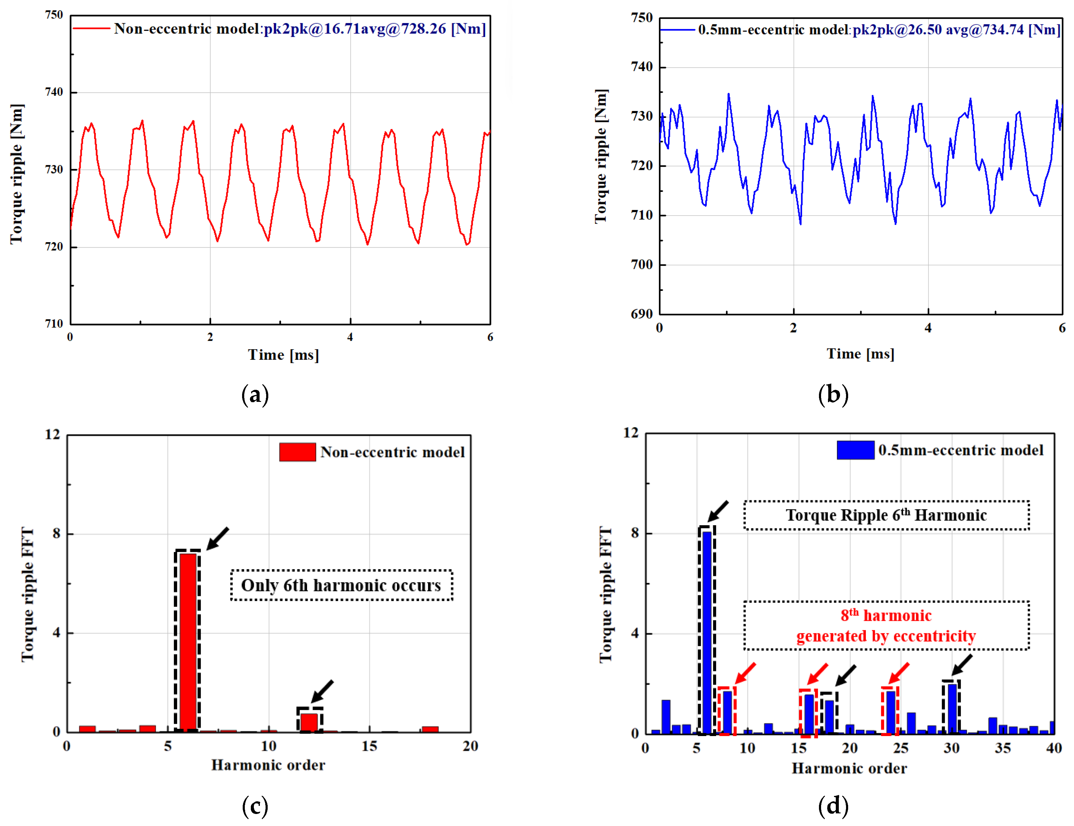
Figure 2a shows the torque ripple variation according to the degree of eccentricity, and Figure 2b shows the torque ripple waveform when 0.5 mm of radial eccentricity is applied. Figure 2c,d show the torque ripple FFT results for the normal and eccentric models, respectively. At 0.5 mm of eccentricity, the peak-to-peak value of the torque ripple increased from 16.71 N·m to 26.50 N·m, representing a relative increase of approximately 58.6%. The waveform also exhibited abnormal irregularity, indicating distortion due to the asymmetry of the magnetic flux distribution.
Typically, in a three-phase balanced system, the 3nth harmonic cancels out and has no effect on torque. The torque ripple component is generated by the counter-electromotive force, which includes the 6n ± 1st harmonic.
When eccentricity is present, additional harmonics are induced due to the asymmetry of the air gap. Specific 5th and 7th harmonics interact with the fundamental, generating torque components (∣7 ± 1∣ = 6th and 8th). Therefore, in experiments and simulations, the 6th order represents the fundamental torque ripple due to the design structure, while the 8th order represents the newly induced torque component due to eccentricity. Typically, in a three-phase balanced system, the 3nth harmonic cancels out and has no effect on torque. The torque ripple component is generated by the counter-electromotive force, which includes the 6n ± 1st harmonic.
When eccentricity is present, additional harmonics are induced due to the asymmetry of the air gap. Specific 5th and 7th harmonics interact with the fundamental, generating torque components (∣7 ± 1∣ = 6th and 8th). Therefore, in experiments and simulations, the 6th order represents the fundamental torque ripple due to the design structure, while the 8th order represents the newly induced torque component due to eccentricity. This indicates not only an abnormal increase in torque ripple but also a potential negative impact on NVH characteristics. Furthermore, the torque ripple ratio relative to the average torque in this model increased by approximately 57.6%, from approximately 2.29% in the steady state to 3.61% in the eccentric state. This indicates that, although the absolute threshold value is not exceeded, self-symmetry deteriorates rapidly when eccentricity occurs, demonstrating that not only the absolute value but also the rate of change in torque ripple can be a valid indicator of eccentricity diagnosis.
Additionally, the torque ripple FFT under eccentricity conditions shows several minor harmonic components in addition to the dominant 6th and 8th orders. These harmonics are considered to be induced by eccentricity, as the asymmetrical magnetic flux distribution generates additional components. However, their amplitudes are significantly smaller than those of the 6th and 8th orders, and their impact on the overall torque ripple characteristics is negligible.
Table 2 shows the following changes in the electromagnetic characteristics of the generator under steady and eccentric conditions.
First, the back-EMF decreased slightly from 861.5 V to 859.17 V, and the THD increased slightly from 21.07% to 21.22%. Power decreased from 77.09 kW to 74.85 kW, and the average torque decreased from 669.24 Nm to 665.77 Nm. Furthermore, torque ripple increased from 12.7% to 15.1%, confirming the influence of eccentricity. In terms of losses, core loss increased from 3.84 kW to 5.65 kW, and eddy current loss increased from 0.53 kW to 0.9 kW. In particular, the iron loss increased significantly due to magnetic flux saturation in the rotor back yoke due to the reduction in air gap length caused by eccentricity, and the overall efficiency decreased from 94.03% to 91.2% due to this increase in loss.

3.3. Electromagnetic Force Characteristic

The electromagnetic force generated in the air gap between the stator and the rotor is derived from the Maxwell stress tensor, which is expressed in Equation (2) as follows:
F = 1 μ 0 ( B r 2 1 2 B 2 ) i r + 1 μ 0 B r B θ i θ
Equation (2) can be divided into the radial gap electromagnetic force density and the circumferential gap electromagnetic force, which are expressed by Equations (3) and (4), respectively.
f r = 1 2 μ 0 ( B r g 2 B θ g 2 )
f θ = 1 2 μ 0 B r g B θ g
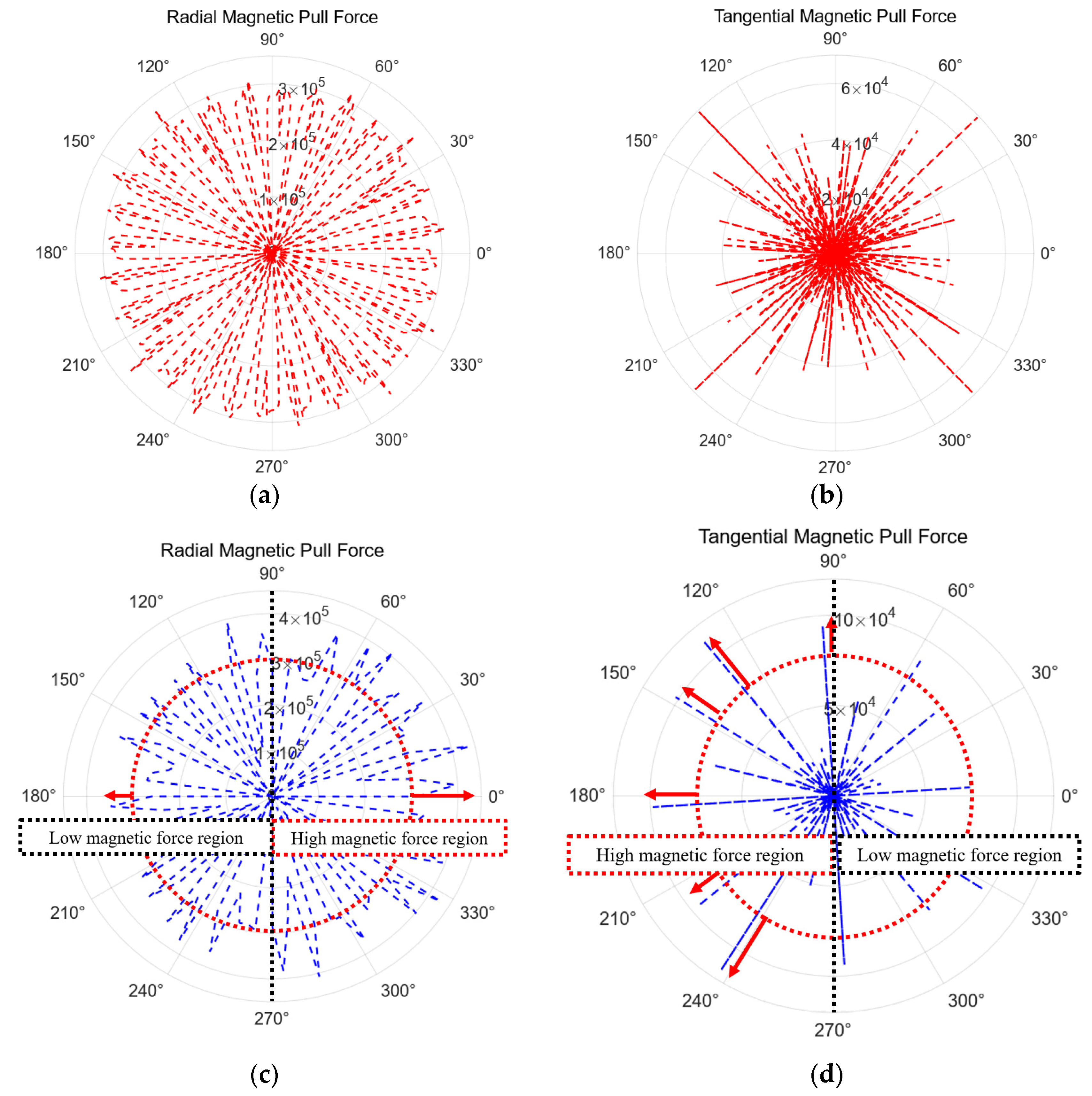
Figure 3 shows the magnetic pull force of radial and tangential components in the steady state and eccentric state. Figure 3a,b show symmetrical forces in both radial and tangential, while Figure 3c,d show that the radial and tangential forces are not symmetrical due to the eccentricity [16].
From Equations (3) and (4), the unbalanced electromagnetic forces in the X and Y directions can be derived as Equations (5) and (6).
F x = r l s t k 2 μ 0 0 2 π [ ( B θ g 2 B r g 2 ) cos θ 2 B r g B θ g sin θ ] d θ
F y = r l s t k 2 μ 0 0 2 π [ ( B θ g 2 B r g 2 ) sin θ 2 B r g B θ g cos θ ] d θ
Here, lstk, Bθg, and Brg are the axial length, circumferential air gap flux density, and radial air gap flux density, respectively [16].
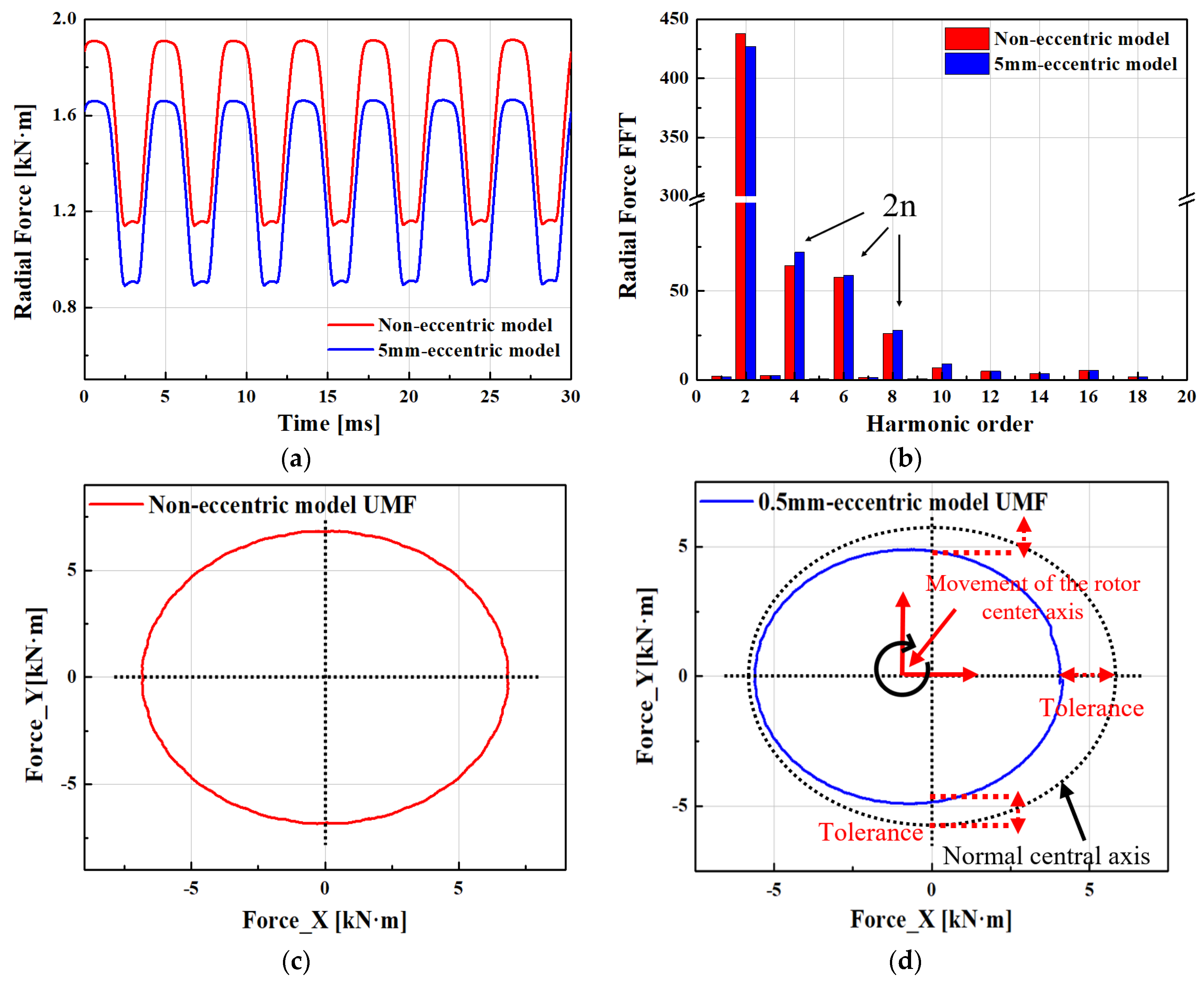
Figure 4a shows the radial gap magnetic flux density of the steady-state model derived from the above equation and the model with eccentricity applied. Figure 3b shows the FFT results of the radial gap magnetic flux density. When eccentricity occurs, the gap narrows in some areas and widens in other areas. Accordingly, the magnetic flux density increases in the narrowed area and decreases in the widened area, and as a result, the radial magnetic flux distribution becomes asymmetric. This asymmetry of the magnetic flux causes an unbalanced electromagnetic force. When eccentricity occurs, the magnetic flux density by area becomes asymmetric and a distribution biased toward a specific direction occurs. Accordingly, it was confirmed that the 2nth harmonic in the magnetic flux density increases. This means that the 2nth harmonic indicates the eccentricity of the rotor, gap imbalance, and asymmetric flux distribution. Figure 4c,d show the unbalanced electromagnetic force due to eccentricity. Under steady-state conditions, the unbalanced electromagnetic force shows parallel magnitudes along the X- and Y-axes. In the presence of rotor eccentricity, the force distribution becomes asymmetric relative to the center.

4. Mechanical and NVH Analysis

4.1. Modal Analysis

Mechanical excitation sources such as mass imbalance and rotor eccentricity primarily produce low-frequency components, which must be accounted for in vibration analysis. In contrast, electromagnetic excitation can induce structural responses at frequencies that align with the natural frequencies of the stator or rotor, significantly amplifying vibrations when resonance occurs [17].
Therefore, accurately identifying the structural properties of the machine particularly its natural frequencies and associated mode shapes is essential. Since the stator is the main structural component directly subjected to electromagnetic forces, its resonant frequencies often fall within the operational frequency range and largely determine the machine’s overall vibration and acoustic behavior. Accordingly, a systematic investigation of the stator’s natural frequencies and mode shapes is a prerequisite for understanding and optimizing the motor’s dynamic performance and NVH characteristics.
The classical formula used to estimate the natural frequency of a generator stator is given by Equation (7).
f m = 1 2 π k m M m
where km is the equivalent stiffness and Mm is equivalent mass. As the stiffness increases, the natural frequency increases, and as the mass increases, the natural frequency decreases.
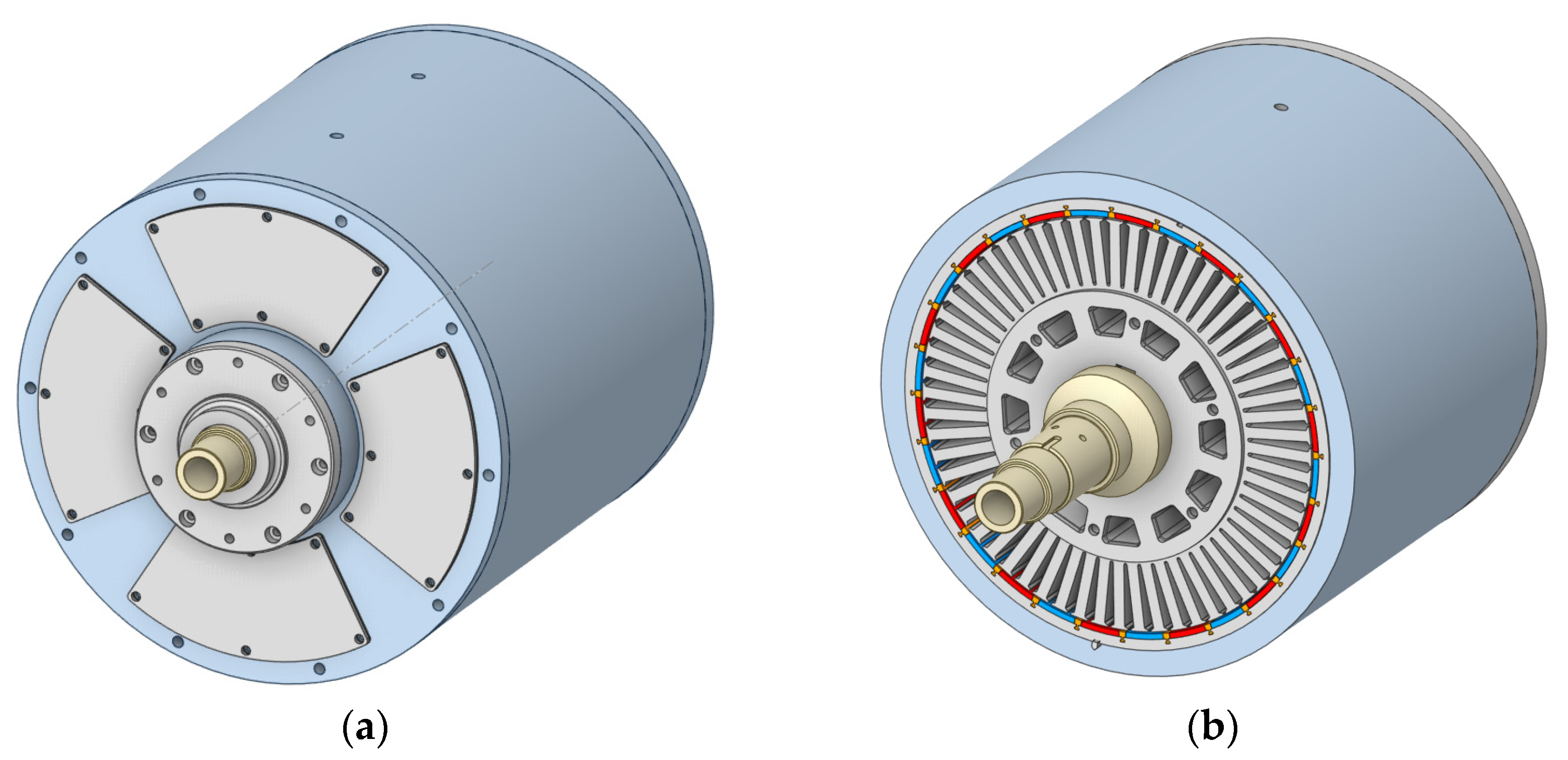
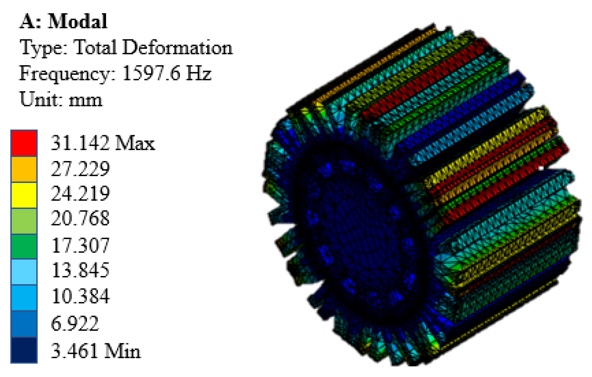
Figure 5 shows the 3D analysis model for coupled analysis. Figure 6 shows the circumferential mode shapes of each stator unit structure. Modal analysis results revealed that the stator’s natural frequency is 1600 Hz. Since the rotor rotational frequency, slot passing frequency, and major harmonic frequencies do not coincide with this natural frequency within the operating speed range, stator resonance does not occur during normal operation. Therefore, this study demonstrates that the increased noise and vibration observed in this study is not due to the stator’s natural vibration modes, but rather to rotor eccentricity.

4.2. Rotor Dynamics

Accurate prediction of the natural frequencies and vibration modes of the rotor is essential during the early design stage. In particular, vibrations near the critical speed can directly affect the structural stability of the rotor system and must be carefully evaluated.
The critical speed is defined as the rotor speed at which resonance occurs, i.e., when the rotational speed matches a natural frequency. At this point, vibration amplitudes increase rapidly, potentially resulting in contact with the stator, bearing failure, or even catastrophic damage [18]. This speed is influenced by rotor geometry, shaft stiffness, mass distribution, and bearing conditions.
Rotor vibration can be broadly categorized into rigid-body modes and bending modes. Most machines operate between these two modes, but as the rotor approaches the first bending mode frequency, significant high-frequency vibrations may occur. In this study, critical speed analysis was conducted using an FEM, as represented in Equation (8).
M x ¨ ( t ) + ( C + Ω G ) x ˙ ( t ) + K x ( t ) = f n ( Ω )
where M, C, G, K, and Ω represent the mass matrix, damping matrix, gyroscopic matrix, stiffness, and rotational speed (rad/s), respectively [19].
Among various types of vibration, transverse (bending) vibration is of primary interest in this work, as it is a common source of structural damage and vibration-induced noise [20,21].
Accordingly, this study focuses on synchronous transverse vibration caused by rotor eccentricity. Torsional and axial vibrations are acknowledged but are outside the scope of this analysis.
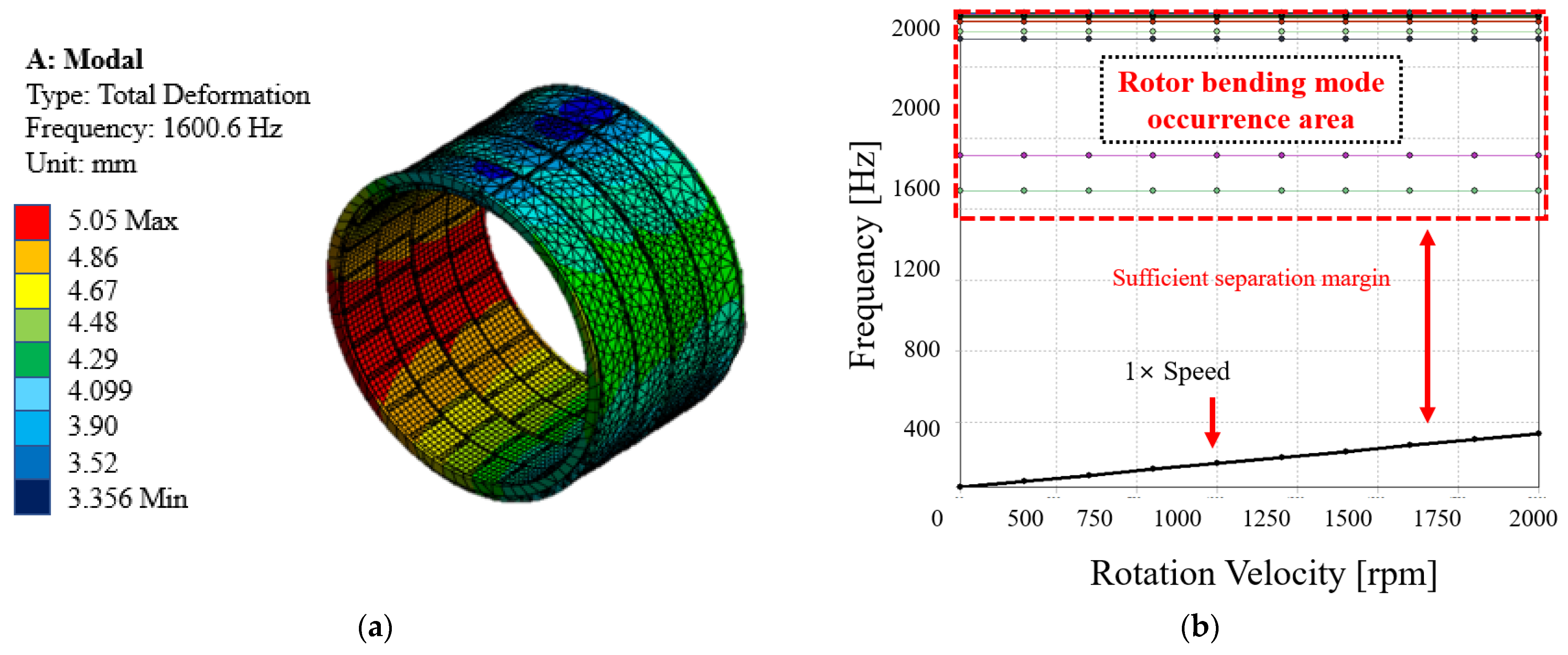
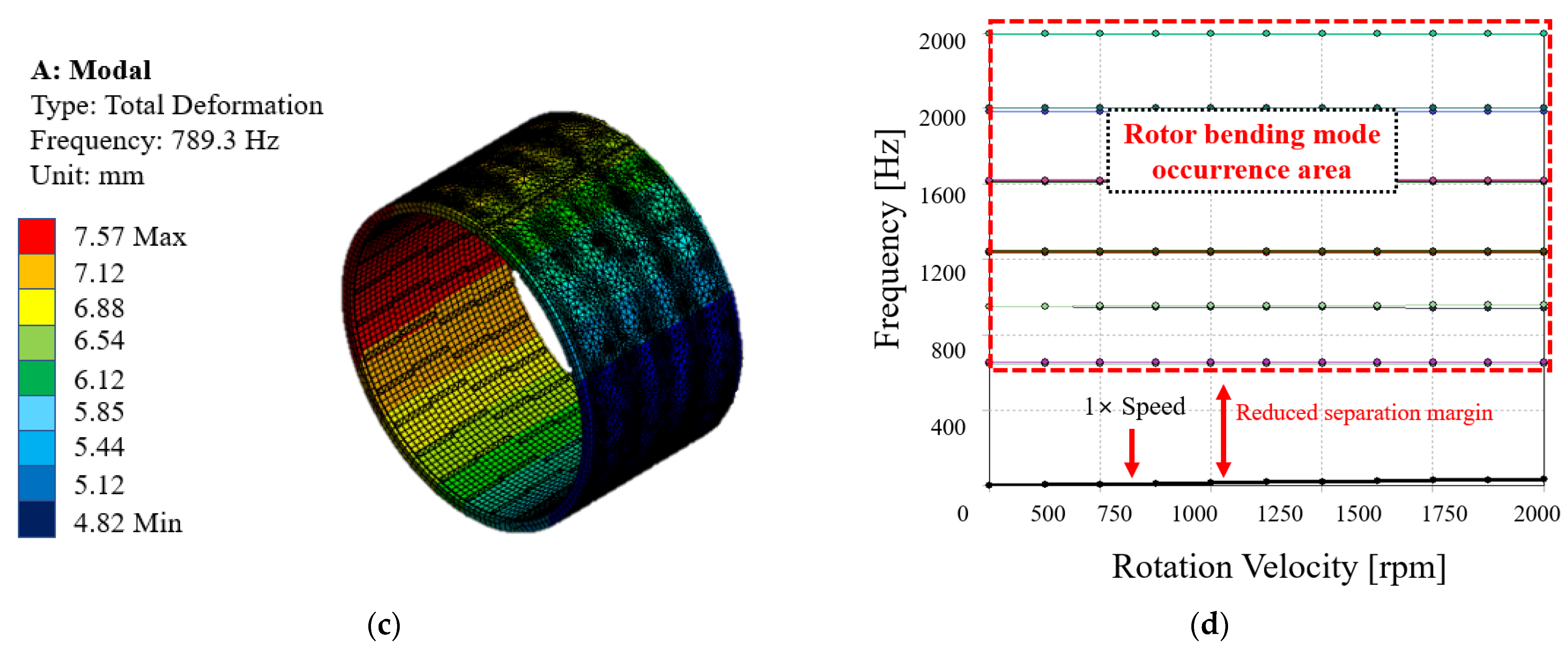
Figure 7 shows the rotor bending mode and Campbell diagram derived through finite element analysis. This visualizes the change in natural frequency according to the rotational speed of the rotor and is a representative tool for predicting the possibility of resonance. The horizontal axis represents the rotational speed, the vertical axis represents the natural frequency, and the point where they intersect represents the critical speed at which resonance is likely to occur.

4.3. Coupled Electromagnetic–Mechanical NVH Evaluation

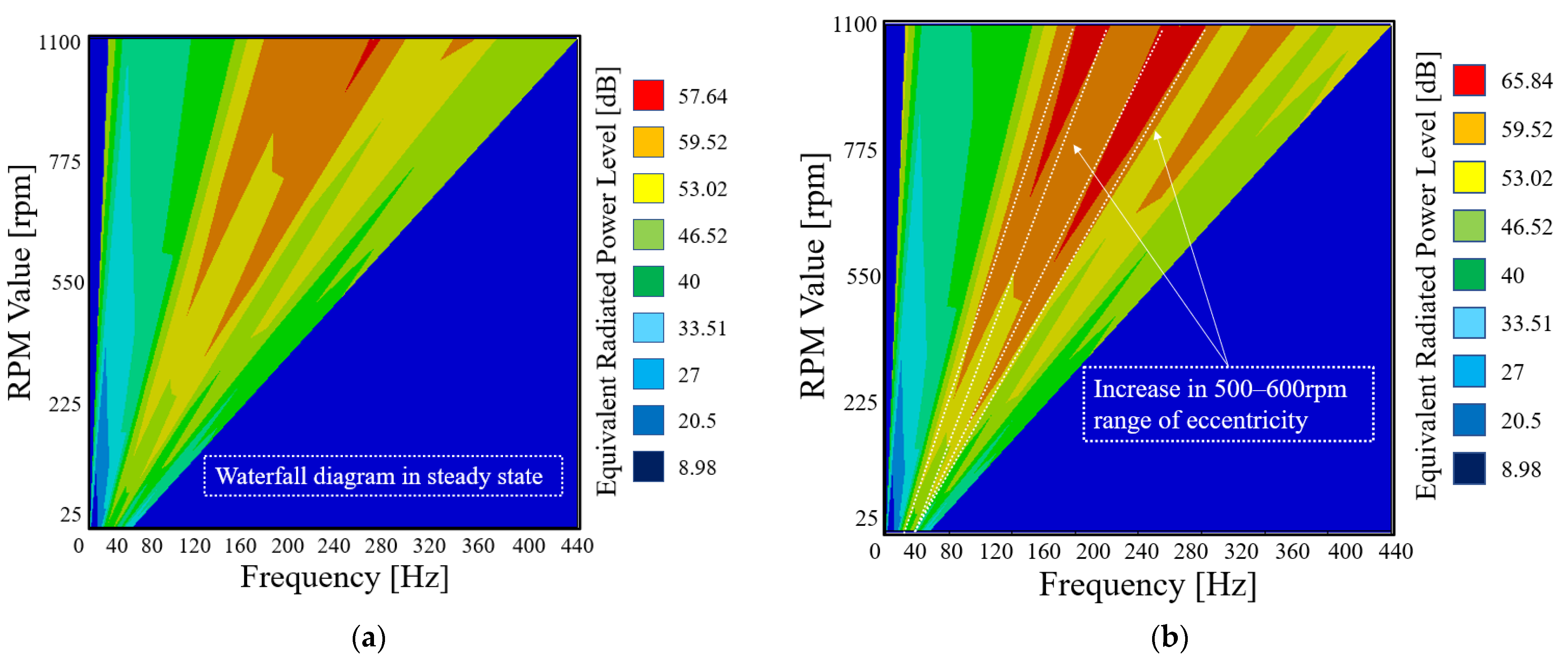
Figure 8a,b show the NVH analysis results under normal and eccentric conditions, respectively. The mechanical coupling analysis used the ANSYS Maxwell (2024 R1) 2D model to calculate the air gap flux density and derive the electromagnetic force. The 3D NVH analysis was performed by mapping to the ANSYS Workbench (2024 R1) Harmonic Response analysis, and the calculated electromagnetic force was applied to the 3D NVH model, assuming that it is uniformly distributed in the circumferential and axial directions. Mesh independence was verified using the mesh quality function provided within the analysis tool, and the results were confirmed to be more than 90% stable. Based on the above, a waterfall diagram was derived. The analysis results showed an increase of SPL from approximately 59 dB to 65.84 dB (+6.84 dB) between 500 and 600 rpm range. This data is shown in Table 3.
This noise increase is believed to be due to mechanical and electrical imbalance caused by eccentricity. As the rotational speed increases, the effects of this imbalance tend to be mitigated by centrifugal force. These results indicate that if a similar level of SPL change is observed during outer-rotor PMSG operation, an eccentricity of approximately 0.5 mm is likely to occur. Therefore, SPL monitoring can be used as a diagnostic indicator to quantitatively estimate the degree of eccentricity during operation.

5. Experimental Setup and Validation

Figure 9 shows the experimental setup used for practical validation. During fabrication, an eccentricity of approximately 0.5 mm occurred on the rotor shaft. To quantitatively assess its effects, electromagnetic and mechanical measurement equipment was installed. Electromagnetic characteristics were measured using voltage and current probes along with an oscilloscope, while mechanical characteristics were obtained using a microphone, accelerometer, and signal conversion unit. Acoustic measurements were performed by installing a microphone at a distance of more than 15 cm from the measurement target. The experiment was conducted in a wide, anechoic space, and the surrounding external noise was blocked. The sound pressure level (SPL) was analyzed by applying an A-weighting filter, and the equipment used for the measurement was a precision sound level meter with an open circuit sensitivity of −25.6 dB re 1 V/Pa (approximately 52.5 mV/Pa) and suitable for measuring vibration noise. The background noise was checked separately before the measurement and was confirmed to be at a level that did not affect the measured value.
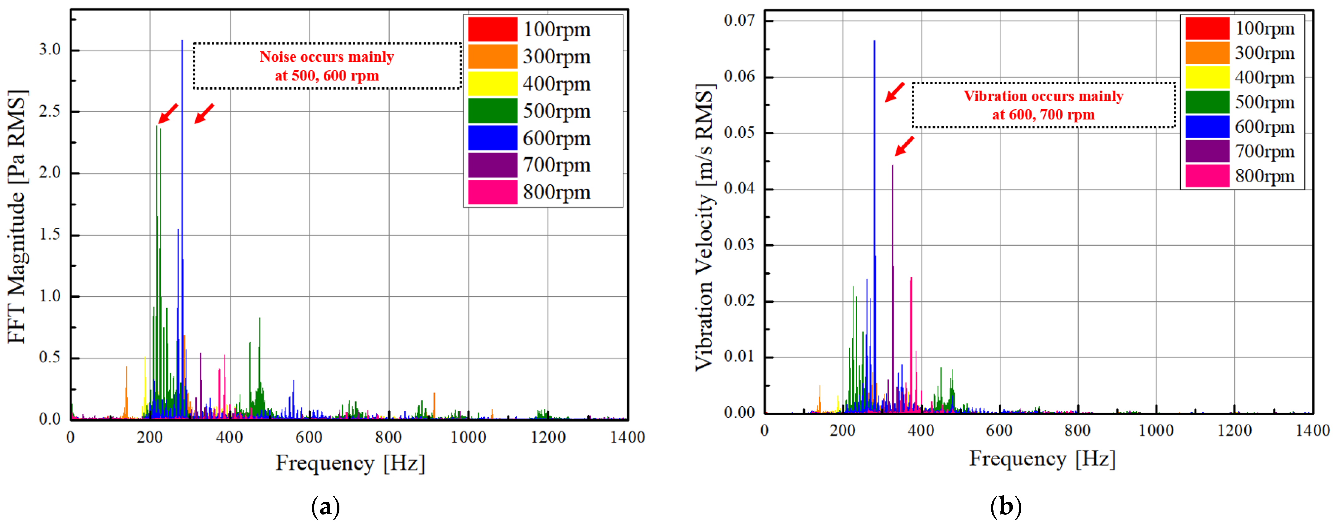
Figure 10a,b present the experimental setup used for validation tests and the measurement results obtained through vibration and electromagnetic characteristic analysis equipment. Figure 10a shows the sound pressure spectrum measured using a microphone, while Figure 10b illustrates the vibration velocity spectrum obtained via an accelerometer. For quantitative analysis, time-domain signals were acquired using a data acquisition board. The generator was operated under no-load conditions, and measurements were conducted by incrementally increasing the rotational speed from 100 rpm to 800 rpm in steps of 100 rpm. The analysis revealed that the sound pressure spectrum exhibited a significant increase in amplitude within the 500–600 rpm range, while the vibration velocity spectrum showed a pronounced rise in amplitude between 600 and 700 rpm. These results are consistent with the NVH waterfall diagram presented in Figure 7, which reveals an approximate 8 dB increase in the 500–800 rpm range, indicating the presence of electromagnetic and structural resonance within this speed range.

6. Conclusions

This study investigated the electromagnetic excitation characteristics of an outer-rotor PMSG for wave energy applications by incorporating rotor eccentricity into two-dimensional FEM analysis and validating the results through experimental measurements. When a rotor eccentricity of 0.5 mm was introduced, the generator exhibited in-creased torque ripple, amplified radial harmonic components, and the generation of un-balanced electromagnetic forces. FFT analysis of the torque ripple revealed the emergence of the eighth harmonic in addition to the sixth, indicating asymmetric electromagnetic excitation due to eccentricity.
Three-dimensional FEM analysis was additionally performed to assess NVH characteristics under eccentric conditions, revealing increased vibration and noise levels in the 500–600 rpm range. The strong agreement between simulation results and experimental data confirms the reliability and predictive capability of the proposed analysis methodology.
This study can be utilized to predict and analyze vibration and noise characteristics due to eccentricity during the design and testing of external-rotor or permanent magnet synchronous generators. By preemptively reviewing the various analysis techniques proposed above, vibration and noise issues can be prevented during the generator design phase. Furthermore, based on the torque ripple, FFT, and UMF data presented above, this study provides basic data for predicting eccentricity without the need for separate precision measurements. Therefore, this study can serve as a foundation for generator NVH characteristic analysis and design optimization.

Author Contributions

J.-Y.C.: conceptualization, review and editing; K.-H.S.: conceptualization, review and editing; W.-S.J.: analysis, original draft preparation; Y.-T.C.: co-simulation; Y.-S.K.: co-simulation. All authors have read and agreed to the published version of the manuscript.

Funding

This research was funded by the Korea Institute of Marine Science & Technology Promotion (KIMST), funded by the Ministry of Oceans and Fisheries, grant number 00254688.

Institutional Review Board Statement

Not applicable.

Informed Consent Statement

Not applicable.

Data Availability Statement

The data presented in this study are available on request from the corresponding author.

Conflicts of Interest

The authors declare no conflicts of interest.

References

  1. Dutta, R.; Rahman, M.F.; Chong, L. Winding Inductances of an Interior Permanent Magnet Machine with Fractional Slot Concentrated Winding. IEEE Trans. Magn. 2012, 48, 4842–4849. [Google Scholar] [CrossRef]
  2. Zou, J.; Lan, H.; Xu, Y.; Zhao, B. Analysis of Global and Local Force Harmonics and Their Effects on Vibration in Permanent Magnet Synchronous Machines. IEEE Trans. Energy Convers. 2017, 32, 1523–1532. [Google Scholar] [CrossRef]
  3. Dong, J.; Huang, Y.; Jin, L.; Lin, H. Comparative Study of Surface-Mounted and Interior Permanent-Magnet Motors for High-Speed Applications. IEEE Trans. Appl. Supercond. 2015, 26, 5200304. [Google Scholar] [CrossRef]
  4. Bang, T.-K.; Shin, K.-H.; Lee, J.-I.; Lee, H.-K.; Cho, H.-W.; Choi, J.-Y. Electro-Mechanical Characteristics Analysis and Experimental Study of PMSM According to Rotor Eccentricity. IEEE Trans. Magn. 2022, 58, 2. [Google Scholar] [CrossRef]
  5. Yang, H.; Chen, Y. Influence of Radial Force Harmonics with Low Mode Number on Electromagnetic Vibration of PMSM. IEEE Trans. Energy Convers. 2014, 29, 38–45. [Google Scholar] [CrossRef]
  6. Ahn, J.-H.; Han, C.; Kim, C.-W.; Choi, J.-Y. Rotor Design of High-Speed Permanent Magnet Synchronous Motors Considering Rotor Magnetic and Sleeve Materials. IEEE Trans. Appl. Supercond. 2015, 28, 3. [Google Scholar]
  7. Zhu, Z.Q.; Liu, Y.; Howe, D. Minimizing the Influence of Cogging Torque on Vibration of PM Brushless Machines by Direct Torque Control. IEEE Trans. Magn. 2006, 42, 3512–3514. [Google Scholar] [CrossRef]
  8. Torregrossa, D.; Peyraut, F.; Fahimi, B.; M’bOua, J.; Miraoui, A. Multiphysics Finite-Element Modeling for Vibration and Acoustic Analysis of Permanent Magnet Synchronous Machine. IEEE Trans. Energy Convers. 2011, 26, 490–500. [Google Scholar] [CrossRef]
  9. Huo, M.; Wang, S.; Xiu, J.; Cao, S. Effect of Magnet/Slot Combination on Triple-Frequency Magnetic Force and Vibration of Permanent Magnet Motors. J. Sound Vib. 2013, 332, 5965–5980. [Google Scholar] [CrossRef]
  10. Beccue, P.; Neely, J.; Pekarek, S.; Stutts, D. Measurement and Control of Torque Ripple-Induced Frame Torsional Vibration in a Surface Mount Permanent Magnet Machine. IEEE Trans. Power Electron. 2005, 20, 182–191. [Google Scholar] [CrossRef]
  11. Huang, Z.; Fang, J. Multiphysics Design and Optimization of High-Speed Permanent Magnet Electrical Machines for Air Blower Applications. IEEE Trans. Ind. Electron. 2016, 63, 2766–2774. [Google Scholar] [CrossRef]
  12. Zhu, Z.Q.; Howe, D. Influence of Design Parameters on Cogging Torque in Permanent Magnet Machines. IEEE Trans. Energy Convers. 2000, 15, 407–412. [Google Scholar] [CrossRef]
  13. Bang, T.-K.; Shin, K.-H.; Lee, Y.-G.; Lee, J.-I.; Lee, H.-K.; Cho, H.-W.; Choi, J.-Y. Comparative Study of NVH of Permanent Magnet Machines According to Rotor Eccentricity with Fractional Pole/Slot Combinations. IEEE Trans. Appl. Supercond. 2022, 32, 6. [Google Scholar] [CrossRef]
  14. Kim, D.-Y.; Park, M.-R.; Sim, J.-H.; Hong, J.-P. Advanced Method of Selecting Number of Poles and Slots for Low-Frequency Vibration Reduction of Traction Motor for Elevator. IEEE/ASME Trans. Mechatronics 2017, 22, 1554–1562. [Google Scholar] [CrossRef]
  15. Cieras, J.F.; Wang, C.; Lai, J. Noise of Poly-Phase Electric Motors; Taylor & Francis: New York, NY, USA, 2006. [Google Scholar]
  16. Damiano, A.; Floris, A.; Fois, G.; Marongiu, I.; Porru, M.; Serpi, A. Design of a High-Speed Ferrite-Based Brushless DC Machine for Electric Vehicles. IEEE Trans. Ind. Appl. 2017, 53, 4279–4287. [Google Scholar] [CrossRef]
  17. Musuroi, S.; Sorandaru, C.; Greconici, M.; Olarescu, V.; Weinman, M. Low-Cost Ferrite Permanent Magnet Assisted Synchronous Reluctance Rotor: An Alternative for Rare Earth Permanent Synchronous Motors. In Proceedings of the 39th Annual Conference of the IEEE Industrial Electronics Society, Vienna, Austria, 10–13 November 2013; pp. 2966–2970. [Google Scholar]
  18. Huo, Q.; Han, J.; Wei, P. PMSM Servo Control System Design Based on Fuzzy PID. In Proceedings of the International Conference on Cybernetics, Robotics and Control, Chengdu, China, 21–23 August 2017; pp. 85–88. [Google Scholar]
  19. Zhang, W.; He, Y.L.; Dai, D.R.; Liu, Z.H.; Xu, M.X.; Gyselinck, J.; Zhang, F.; Gerada, D. UMF and Vibration Analysis for Eccentricity Detection in Permanent Magnet Synchronous Generators. IEEE Trans. Transp. Electr. 2025, in press.
  20. Wang, J.; Wang, Y. Electromagnetic Torque Analysis and Structure Optimization of Interior Permanent Magnet Synchronous Machine with Air-Gap Eccentricity. Energies 2023, 16, 1665. [Google Scholar] [CrossRef]
  21. Perez, R.; Cros, J.; Picard, M. Real-Time Modeling of Static, Dynamic and Mixed Eccentricity in Permanent Magnet Synchronous Machines. Machines 2025, 13, 120. [Google Scholar] [CrossRef]
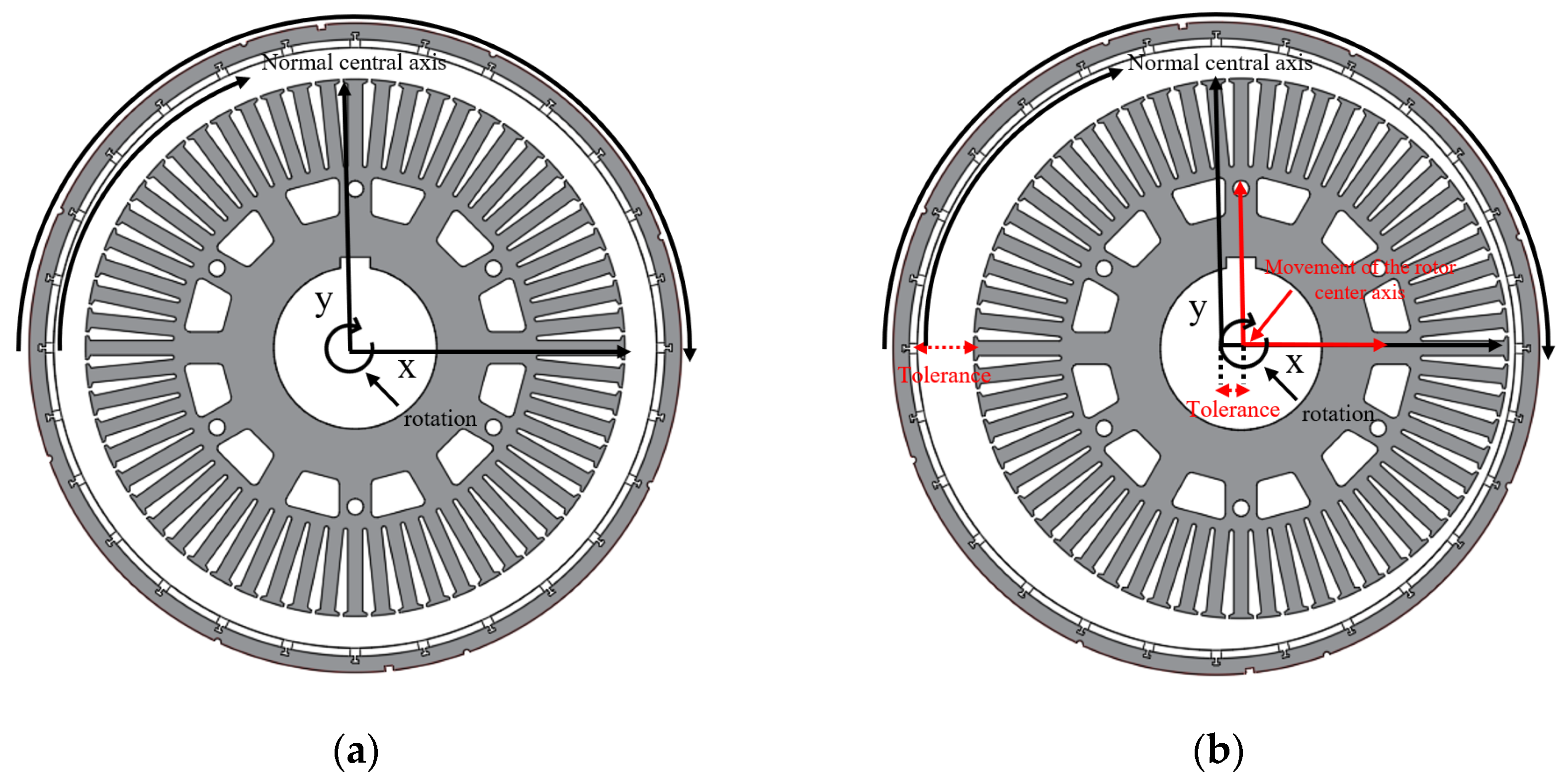
Figure 1. Two-dimensional FEM models of the SPMSG: (a) baseline model under steady-state condition; (b) model with 0.5 mm rotor eccentricity.
Applsci 15 09697 g001
Figure 2. Torque characteristic analysis results: (a) torque ripple in steady state; (b) torque ripple when eccentricity occurs; (c) torque ripple FFT in steady state; (d) torque ripple FFT when eccentricity occurs.
Applsci 15 09697 g002
Figure 3. Magnetic pull force analysis results: (a) radial magnetic pull force at steady state; (b) tangential magnetic pull force at steady state; (c) radial magnetic pull force at eccentricity; (d) tangential magnetic pull force at eccentricity.
Applsci 15 09697 g003
Figure 4. Magnetic pull force analysis results: (a) radial gap magnetic flux density; (b) FFT of radial gap magnetic flux density; (c) unbalanced electromagnetic force in steady state; (d) unbalanced electromagnetic force in non-eccentric state.
Applsci 15 09697 g004
Figure 5. Three-dimensional FEM models for coupled analysis of SPMSG: (a) assembly geometry; (b) internal geometry.
Applsci 15 09697 g005
Figure 6. Modal analysis results of the SPMSG stator.
Applsci 15 09697 g006
Figure 7. Results of mechanical analysis of the outer rotor type PMSG rotor: (a) analysis of bending mode according to rotor speed in steady state; (b) Campbell diagram in steady state; (c) analysis of bending mode according to rotor speed in eccentric state; (d) Campbell diagram in eccentric state.
Applsci 15 09697 g007aApplsci 15 09697 g007b
Figure 8. NVH waterfall diagrams derived from coupled electromagnetic–mechanical analysis: (a) steady state; (b) with 0.5 mm rotor eccentricity.
Applsci 15 09697 g008
Figure 9. Experimental setup for electromagnetic and NVH measurements of the SPMSG.
Applsci 15 09697 g009
Figure 10. Measured NVH responses under no-load operation: (a) sound pressure level spectrum obtained from microphone measurements and (b) vibration velocity spectrum obtained from accelerometer measurements.
Applsci 15 09697 g010
Table 1. Specifications of the outer-rotor SPMSG.
ParametersValuesParametersValues
Inner diameter of rotor444 mmNumber of poles28
Outer diameter of rotor480 mmNumber of slots60
Inner diameter of stator111.8 mmNumber of turns4
Outer diameter of stator440 mmCurrent density5 A/mm2
Stack280 mmMagnet materialN45SH
Pole arc ratio0.85Core material35JN270
Table 2. Comparison of electromagnetic characteristics: eccentricity vs. non-eccentricity.
ParametersEccentricityNon-EccentricityUnit
Back-EMF861.5859.17V
Back-EMF THD21.0721.22%
Power77.09 kW74.85kW
Torque669.24 Nm665.77Nm
Torque ripple12.715.1%
Core loss3.84 kW5.65kW
Eddy current loss0.530.9kW
Efficiency94.0391.2%
Table 3. NVH analysis values under normal and eccentric conditions.
ParametersValue
SPL in normal state59 dB
SPL in eccentric state65.84 dB
Increase in dB+6.84 dB
Disclaimer/Publisher’s Note: The statements, opinions and data contained in all publications are solely those of the individual author(s) and contributor(s) and not of MDPI and/or the editor(s). MDPI and/or the editor(s) disclaim responsibility for any injury to people or property resulting from any ideas, methods, instructions or products referred to in the content.