Article

Solid-Solution Evolution Behavior of Al-Cu3-Si-Mg During the MMDF Process

by
Tong Wu
,
Shuming Xing
* and
Guangyuan Yan
School of Mechanical, Electronic and Control Engineering, Beijing Jiaotong University, Beijing 100044, China
*
Author to whom correspondence should be addressed.
Appl. Sci. 2025, 15(17), 9478; https://doi.org/10.3390/app15179478
Submission received: 6 May 2025 / Revised: 24 June 2025 / Accepted: 26 August 2025 / Published: 29 August 2025

Abstract

Al-Cu3-Si-Mg alloy prepared by molten metal die forging (MMDF) under a pressure of 118 MPa was solution-treated at different temperatures and times, and the evolution behavior of the non-equilibrium eutectic in the microstructure was observed using an optical microscope and scanning electron microscope. The results show that the initial solidification structure of Al-Cu3-Si-Mg before solution treatment consists of irregular eutectic (α+Al2Cu), strip compound Q (Al5Cu2Mg8Si6), polygonal phase φ(AlxTi9La2Ce6Cu), spherical particle θ(Al2Cu) and cross-shaped β(Mg2Si) near the grain boundary. After solution treatments, the irregular eutectic at grain boundaries is dissolved. In the solution temperature range of 480 °C~510 °C, the irregular eutectic fraction decreased with the increase in solution temperature, and the grain size of other compounds such as Q (Al5Cu2Mg8Si6) and the spherical particle phase θ(Al2Cu) also showed a decreasing trend. However, all phases do not change significantly with the increase in solution temperature when the solution temperature is between 510 °C and 540 °C. It was determined experimentally that the holding time of 30 min at each temperature is the solution limit. Based on the experimental results, a dissolution model of intergranular irregular eutectic was established as d E d t = 4 P π t D + 2 r k k P D .

.

1. Introduction

2A50 aluminum alloy (YS standard) is an Al-Cu3-Si-Mg wrought aluminum alloy, which is heat-treatable and strengthened; the hardening mechanism is generally precipitation hardening. However, there is little difference between the temperature of the full solid solution of a soluble phase and the temperature of eutectic melting, and oversintering easily occurs in the process of heat treatment [1,2]. As a near net molding process, molten metal die forging (MMDF) injects a certain amount of molten metal into the metal mold cavity and applies constant static pressure, making the molten metal solidify under the pressure. Due to the characteristics of alloying elements, non-equilibrium solidification occurs in the Al-Cu3-Si-Mg alloy during the preparation process, and irregular eutectic structures appear at grain boundaries when this alloy is prepared by MMDF [3,4]. The subsequent heat treatment process can make such an irregular eutectic with adverse effects on the dissolved matrix; then, the precipitate is slowly dispersed and the uniform enhanced phase enhances the mechanical properties of the material [5,6]. The evolution of the irregular eutectic structure under different solution parameters, including its dissolution behavior at grain boundaries, has become an urgent problem to be solved.
In general, the optimal solution treatment needs to obtain the highest possible solute atomic saturation, control the coarsening of Al grains and Si phases, and avoid the oversintering of low-melting eutectic structures. The study of Han showed that the control factors of a solid solution of Al-Si-Cu-Mg (319) alloy include the resolution of the small-size Al2Cu phase, the low-melting eutectic phase Al5Mg8Cu2Si6, the oversintering of the massive Al2Cu phase and the spheroidization of the Si phase [7]. The Al5Mg8Cu2Si6 phase and the large undissolved Al2Cu phase of Al-Si-Cu-Mg (319) alloy display an initial melting phenomenon when the alloy is soldered at 520 °C. Lombardi [8] considered that a more suitable solution treatment for Al-8Si-3Cu-0.3Mg alloy was 500 °C × 2 h. Al5Mg8Cu2Si6 and Al2Cu phases also appear in the initial melting and oversintering of 515 °C and 530 °C solutions. Lasa and Rodriguez-Ibabe [9] compared the remelting behavior of the Al2Cu phase in the gravity casting and thixotropic casting of Al-Si-Cu-Mg alloys. The results show that, with the same alloy composition, the large diameter of thixotropic casting is more adequate than that of the Al2Cu phase at 500 °C. This showed that the second-phase morphology is also a factor to be considered in optimizing solution parameters. The research of Mohamed showed that Al-Si-Cu-Mg (319) alloys with higher contents of Fe and Ni for industrial use have higher thermal stability than experimental alloys with lower contents of Fe and Ni [10]. However, the solution temperature should also be controlled below 520 °C to avoid oversintering. Feng [11] studied the solution behavior of spray-formed hypereutectic Al-Si-Cu-Mg alloy. Over the temperature range of 475 °C–495 °C, the precipitated Al2Cu phase and some of the eutectic Al2Cu phase redissolved, and the residual Al2Cu phase concentrated to a Fe-bearing phase and coarsened. The volume fraction and size of the Al-Cu-Si-Mg phase increased. However, when solution-treated at less than 515 °C, the volume fraction of the Al-Cu-Si-Mg phase began to decrease, and no oversintering structure was observed. G. Dell’Avvocato [12] investigated the anti-correlation between thermal diffusivity and ultimate tensile strength (UTS) in Usibor 1500 steel, an empirical power–law equation was derived to estimate UTS based on thermal diffusivity variations, providing a non-destructive thermographic procedure for UTS estimation in Usibor 1500 steel and offering valuable material property insights. Studies have previously been conducted on the microstructure of Al-Cu alloy under different solution parameters, but few studies have been conducted on the evolution of an intergranular irregular eutectic during the heat treatment of high-strength aluminum alloys with similar compositions under non-equilibrium solidification.
It is known that the diffusion of atoms is the essence of solution and dissolution. In recent years, a large number of scholars have used the quantification and modeling of the atomic thermal motion rate in aluminum alloy phase transformation to study the mechanism of atomic motion. Whelan and GRONG proposed a volumetric diffusion kinetic model of second-phase dissolution based on Fick’s diffusion law, which is the most commonly used basic model at present and describes the solid-solution behavior of the spherical phase [13,14]. However, this model cannot produce a closed analytical solution. G Liu et al. established a kinetic model for the dissolution of disk-like second-phase particles [15,16]. At present, the solution kinetics model of the solid-solution process is limited to the spherical or flake second-phase particles precipitated in the solidification process, and there are few studies on the solution kinetics model of an intergranular eutectic structure, especially that which may be formed in deformed aluminum alloy. In this paper, the evolution behavior of the non-equilibrium eutectic structure of Al-Cu3-Si-Mg alloy prepared by MMDF during the solution process was studied experimentally, and the solution kinetics model of the irregular eutectic was established based on the solution model of spherical and flake second-phase particles.

2. Experimental Materials and Methods

The experimental material in this study was based on the 2A50 wrought aluminum alloy (YS standard). For the preparation of aluminum alloy wheels by casting, it is necessary that the raw materials selected have good fluidity. Generally, aluminum alloy casting based on Al-Si or Al-Si-Mg-Cu is adopted. The fluidity of cast aluminum alloys is high, but their strength is generally lower than that of corresponding wrought aluminum alloys [17]. In this study, the liquid die forging process was adopted to prepare the wheel. The application of pressure not only compensates for the forging difficulty of high-strength deformable aluminum alloys caused by poor fluidity, but can also obtain much better mechanical properties than cast aluminum alloys. Therefore, the raw material selected for this experiment is high-strength deformable aluminum–copper alloy 2A50, the main alloying element of which is Cu.
The 2A50 alloy was melted in a melting furnace (YN-R-500-1200T, Shin Hing Technology Co., Ltd., Zhengzhou, China) at 760 °C. The molten metal was poured into a transfer ladle after all the alloy had melted. Then, 2 wt% rod-like Al-10 La/Ce rare earth master alloy with a diameter of 10 mm and length of 50 mm was added into the transfer ladle for modification. The molten metal was then stirred with a graphite rod coated with ZnO for 10 min until it was completely melted. Next, 0.1 wt% Al5Ti1B refiner was put into a bell jar and pressed into the molten metal; then, argon gas was used to degas for 12 min. The molten metal was stirred evenly and the slag was removed. After refining, the molten aluminum alloy was poured into a quantitative pouring machine (W650 SVPC, Chensong Shape Machinery Co., Ltd., Cangzhou, China) to prepare for pouring at a temperature of 739 °C. Melting and pouring steps are shown in Figure 1.
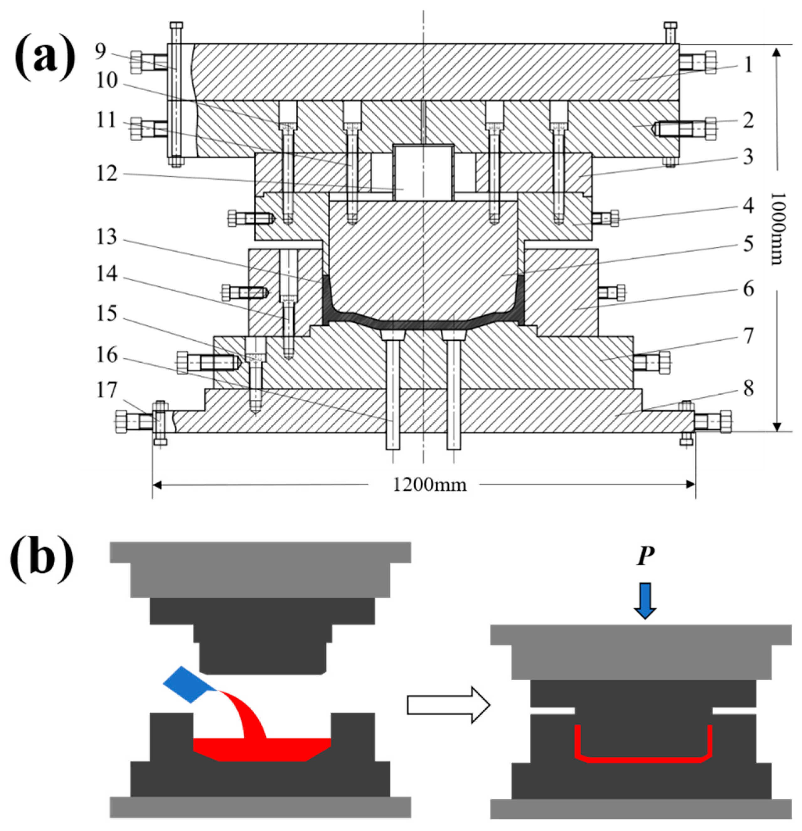
The direct MMDF process was applied in the pressure solidification test of wheel hub. The wheel hub die was installed on a THP16-3000 MMDF hydraulic machine(Tianduan Press Machine Co., Ltd., Tianjin, China). The structure of the hydraulic machine and hub die is shown in Figure 2a. The material of the mold’s body was H13, and the surface received nitriding treatment. The preheating temperature of the mold was 220 °C. Then, molten metal was poured into the center of the mold cavity. The punch went down at a speed of 150 mm/s until it contacted the molten metal; the molten metal was extruded to completely fill the cavity. A pressure of 118 MPa was used for preparation, and the pressure holding time was 27 s. The MMDF process is shown in Figure 2b.
The composition of the heat treatment samples is shown in Table 1. The casting and sampling positions are shown in Figure 3. In order to ensure the accuracy of the experimental results, the position of the heat treatment sample was selected in four symmetrical positions at the bottom of the casting. The samples were made into blocks of 10 × 10 × 10 mm and polished until the surface was flat.
Five solid-solution temperatures and four solid-solution times were symmetrically set to observe the solid-solution structure. A BFX-12C heat treatment resistance furnace (Fulaimeng Experimental Equipment Co., Ltd., Beijing, China) was used for the solution treatment of the samples. The heat treatment samples were placed in the center of the heat treatment furnace and heated for 10 min. After heat preservation, the samples were immediately placed in water for quenching at 25 °C. The solution treatment scheme is shown in Table 2. Ten samples were taken from each parameter for heat treatment experiments. The heat treatment samples were sanded with SiC sandpaper and polished with 0.3 μm Al2O3. The polished samples were then washed in an alcohol solution in an ultrasonic cleaner for 120 s. Finally, Keller reagent (2.5%HNO3, 1.5%HCI, 1%HF, 95%H2O) was used to corrode for 15 s. An optical microscope (OM, DM2000, Leica Co., Ltd., Wetzlar, Germany) and scanning electron microscope (SEM, S4800, Carl Zeiss Co., Ltd., Baden-Württemberg, Germany) were used to observe the solidification microstructures, and 10 fields of view were selected for observation.

3. Experimental Results

3.1. Microscopic Solidified Structure Under Pressure

Figure 4a–d show the solidified micro-structure under the MMDF process. The lamellar or network eutectic structures and dendrites produced by the traditional casting process were not observed. However, it was found that the solidification structure is mainly composed of α-Al matrix. The EDS analysis indicates that the large polygonal gray block phase shown in the figure is the rare earth phase φ(AlxTi9La2Ce6Cu), the bright white phase at the grain boundary is the separated irregular eutectic (α+Al2Cu), and the black phase at the grain boundary intersection is Q (Al5Cu2Mg8Si6), as shown in Figure 4. Part of the bright white Al2Cu phase is distributed uniformly in the α-Al phase matrix, and the rest of the Al2Cu phase and β(Mg2Si) are associated with the separated eutectic at the grain boundary. In addition, the α-Al matrix also contains a small sub-micron second phase and a nano-precipitated phase (Figure 4d). The EDS analysis also shows that these second phases are Cu-rich particles, whose composition is close to Al2Cu. The average diameters of each phase are shown in Table 3.

3.2. Effect of Solution Temperature on Irregular Eutectic Fraction

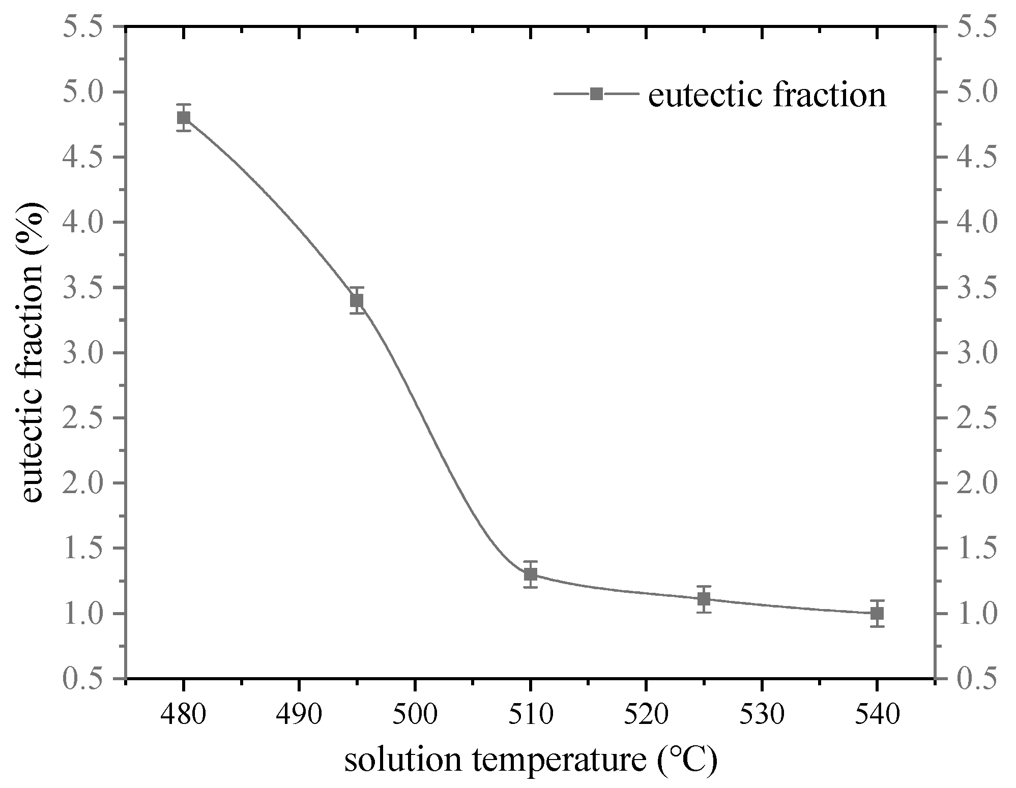
Figure 5 shows high-magnification optical microscope pictures of the as-cast structure at the bottom of wheel hub under MMDF with 118 MPa of pressure and a solid-solution structure held for 60 min at different temperatures. Figure 5b,c correspond to heat treatment samples 1 and 3, respectively. The relatively large irregular eutectic Al2Cu (e) could be found at the grain boundary of the as-cast structure. The area of such a eutectic is calculated by the metallographic analysis software to account for 5.2%. When the solution temperature is 480 °C, the proportion of eutectic area decreases to 4.8%. When the solution temperature is 510 °C, the proportion of eutectic area is 1.2%. When the solution temperature was 540 °C, the irregular eutectic disappeared completely, but the remelting sphere (g) and triangular grain boundary were found at the intersection of grain boundaries (f), and oversintering occurred, as shown in Figure 5d. The quadratic θ(Al2Cu) in the as-cast grains disappeared completely after solution treatment. This rule indicates that 510 °C is the critical solution temperature for this alloy. The variation curve of the eutectic fraction with solid-solution temperature is shown in Figure 6.

3.3. Effect of Solution Temperature on the Morphology and Size of the Irregular Eutectic

Figure 7 shows the separated eutectic structures (α+Al2Cu) at the grain boundaries. These eutectic structures do not have a typical lamellar or skeleton morphology and appear irregular. In the separated eutectic structure, the α eutectic is completely separated from the Al2Cu eutectic. When the eutectic reaction occurs, the eutectic α first grows attached to the primary α-Al, and then grows alone at the final solidification sites, such as at grain boundaries and interdendrites. This kind of irregular eutectic can be regarded as a spherical eutectic at the intercrystalline intersection and a disk-like eutectic at the grain boundary.
Figure 7a shows the definition of the size of such irregular eutectic, and Figure 7b,c are the optical images of the solid solution at 480 °C and 510 °C, respectively. The width of the disk-like eutectic part is d1, while the radius of the spherical eutectic is r1. For each solution temperature, ten fields of view were selected for observation. Ten irregular disk-like eutectic widths d1 and spherical eutectic radii r1 were selected for measurement for each field of view, and the average values were calculated. When the solution temperature is 480 °C–510 °C, it can be found that, with increasing solution temperature, the width of the intercrystalline plate eutectic decreases obviously—from 2.8 μm to 0.3 μm—and the radius of the spherical eutectic at the intersection of grain boundaries decreases obviously—from 2.96 μm to 0.7 μm—as shown in Figure 8. When the solution temperature exceeds 510 °C, the width of the intercrystalline plate eutectic and the radius of the spherical eutectic at the intersection of grain boundaries do not decrease significantly with the increase in solution temperature.

3.4. Effect of Solution Temperature on Compound and Second Phase

Figure 9 shows the definition method for the size and density of the second-phase θ(Al2Cu) and φ(AlxTi9La2Ce6Cu) in α-Al and photoscopic photos of the solid solution at 480 °C and 510 °C. The size of the second-phase θ(Al2Cu) is represented by the diameter of the spherical particle, while the density is represented by the distance between the nearest second-phase particles. The multilateral form can be regarded as a ball, and the size is reflected by the diameter. The diameter of the second-phase θ(Al2Cu) is d2, the diameter of the φ(AlxTi9La2Ce6Cu) is d3, and the distance to the adjacent second-phase θ(Al2Cu) is l2. The measurement scheme was the same as that of the irregular eutectic part.
When the solution temperature is between 480 °C and 510 °C, the second-phase θ(Al2Cu) in α-Al gradually dissolves into the matrix with the increase in temperature, and the grain diameter decreases. In contrast, the grain spacing between adjacent grains increases gradually, and the grain density of the second phase decreases. The grain size and density of θ(Al2Cu) tend to change little when the temperature exceeds 510 °C, as shown as Figure 10. The average diameter of Al2Cu decreases from 0.78 μm to 0.19 μm with the increase in solution temperature, and the distance to the adjacent Al2Cu increases from 66 μm to 120 μm. The morphology and size of the multilateral facies are basically unchanged when the solution temperature is between 480 °C and 540 °C.

4. Discussion

4.1. Analysis of Dissolution Behavior of the Irregular Intergranular Eutectic

In previous work, the solidification path of Al-Cu3-Si-Mg was predicted and the temperature nodes of the phase transition were simulated. The irregular eutectic formation at the grain boundary is the result of non-equilibrium solidification in the MMDF process, which is caused by the separated eutectic reaction with the increase in alloying element content in the remaining liquid phase at the end of solidification. The eutectic Al2Cu with a similar composition to the second-phase Al2Cu is formed at 510 °C~518 °C. When the solution temperature is 480 °C, the irregular eutectic does not dissolve at the grain boundary because the temperature does not reach the reaction range of the separated eutectic temperature, and the area ratio of the irregular eutectic hardly changes. When the solution temperature rises to 510 °C, the lower limit of the separated eutectic reaction temperature range is reached, and Al2Cu in the irregular eutectic begins to dissolve in the matrix, so its content decreases significantly. When the solution temperature reaches 540 °C and the heating temperature is too high, the liquid phase is formed when the solution treatment temperature exceeds the melting point of the eutectic with a low melting point. Due to the action of surface tension, the liquid phase is contracted into a ball; after cooling, it forms a small round ball at the grain boundaries. Triangular grain boundaries occur as a result of local fusion at the junction of three grains.
The dark spherical particles θ(Al2Cu) were the secondary phases precipitated from the primary α–Al solid solution when the temperature dropped below the eutectic line. A size of 2~3 μm cannot strengthen the matrix; it needs to be followed by solution treatment and aging to precipitate the dispersed hardening phase to strengthen the matrix. The density and size of the second-phase θ(Al2Cu) decreased significantly with the increase in solution temperature. Similar to the dissolution of the intercrystalline eutectic structure, it also dissolves in the matrix during the solution process. This can be explained by diffusion theory. The diffusion coefficient of the solute in liquid is not only related to the type and temperature of the system, but also changes with the concentration of the solute. During the solution process, the Cu atoms in the θ(Al2Cu) phase decrease in concentration, and the spheroidal elements dissolve into the matrix gradually. With the increase in solution temperature, this transfer becomes more and more intense, causing the size of the spherical phase to decrease until it disappears. A partially disappeared spherical phase appears alongside a decrease in the density of the second phase.
When there are component differences in a solid, atoms will diffuse from high concentrations to low concentrations. According to Fick’s diffusion law, the flux of atoms in diffusion is directly proportional to the mass concentration gradient. This is shown in Equation (1):
J = D d ρ / d x
where J is the diffusion flux; D is the diffusion coefficient; and ρ is the mass concentration of the diffused substance. The negative sign in the equation indicates that the diffusion direction of the substance is opposite to the direction of the mass concentration gradient, suggesting that the substance migrates from the high-concentration area to the low-concentration area. In this experiment, the copper content in the irregular eutectic e (α+Al2Cu) and the strengthening phase θ(Al2Cu) of the alloy Al-Cu3-Si-Mg in the solidification structure was higher than that in the α-Al matrix. They were solidly dissolved within their respective temperature ranges and gradually merged into the matrix over time.

4.2. Kinetic Model of Irregular Eutectic Dissolution

The dissolution law of the irregular intergranular eutectic can be summarized by the results of the microstructure evolution of Al-Cu3-Si-Mg obtained via solution experiment. The schematic diagram of the solution process of Al-Cu3-Si-Mg alloy under liquid forging conditions is shown in Figure 11. Before solution treatment, the intergranular irregular eutectic appears as the disk-like eutectic formed between two adjacent matrix grains, as shown in Figure 11a. As the solution treatment proceeds, the disk-like eutectic dissolves first, until only the irregular eutectic at the triangular boundary remains, as shown in Figure 11c. The irregular eutectic at the triangular boundary can be regarded as the spherical eutectic. When the solution continues, the spherical eutectic finally dissolves and disappears, as shown in Figure 11d. The dissolution kinetics model of the irregular eutectic can be established according to the basic criterion of dissolving the disk-like eutectic first, and then dissolving the spherical eutectic.
When the second-phase particles are disk-like, the dissolution rate of precipitated particles can be obtained from the solute balance at the interface [14]:
d B d t = k 2 D π t
D = D 0 e x p ( E a / R T )
where B is the mean width of irregular eutectic, D is the diffusion coefficient; k is the kinetic constant when the atoms are uniformly separated in the second phase; D 0 is the diffusion constant, which is related to the material properties; E a is the activation energy of atomic diffusion; R is the gas constant with a value about 8.314 J/(mol·K); and T is the absolute temperature.
Assuming that the interface between the particles of the second phase and the matrix in the irregular eutectic is always in equilibrium, the dissolution process is carried out by diffusion, and the particles are in the infinite matrix during the isothermal process. Whelan [12] proposed a volumetric diffusion kinetic model of second-phase dissolution based on Fick’s diffusion law. When the morphology of the particles of the second phase is spherical, the size changes are balanced according to the solute flow rate, as shown in Equation (4):
d r d t = p D 2 r p 2 D π t 1 / 2
p = 2 ( C i C m C p C i )
where p is the dimensionless concentration parameter, r is the particle radius, and C m is the average solute concentration in the matrix. C i is the interfacial atomic concentration between the second phase and the matrix. C p is the solute concentration of the particle. p D 2 r is derived from the stable part of the diffusion field, while p 2 D π t 1 / 2 is derived from the transition part of the diffusion field. When the holding time is long, the transition part p 2 D π t 1 / 2 becomes very small, so the transition part can be ignored.
Assume that the solution holding time is long enough. During the solution process, the disk-like eutectic is dissolved first, for which the dissolution time is t 1 ; then, the spherical eutectic is dissolved, for which the dissolution time is t 2 . The width B of the disk-like eutectic can be consistent with the diameter 2 r of the spherical eutectic. Disk-like and spherical eutectic dissolution models are, respectively, as follows:
d E = k 4 D π t 1 d t 1 , d E = p D 2 r d t 2
E = r = B / 2
The solution is obtained when the solution time is integrated:
d E d t = 4 P π t D + 2 r k k P D
t = t 1 + t 2
E is the mean radius of the spherical eutectic. When the solution temperature increases, the diffusion coefficient D increases. As can be seen from Equation (3), d E / d t also increases with the increase in diffusion coefficient, indicating that the dissolution rate of the intergranular irregular eutectic is accelerated. Moreover, as D is in the denominator of the model, with the increase in the solution temperature, the slope of the acceleration of the dissolution rate gradually becomes smaller and reaches an extreme value at a certain temperature, i.e., the solution limit, which is consistent with the experimental results.

5. Conclusions

  • The as-cast microstructures of Al-Cu3-Si-Mg alloy were studied by SEM. Separated irregular eutectics (α+Al2Cu) were mainly found at the α-Al grain boundary; the irregular bright white eutectics Al2Cu were distributed separately, while the eutectic α had no obvious characteristics. Spherical granular phases θ(Al2Cu) were found in the primary α-Al. The cross-shaped phases Mg2Si grew near the grain boundaries inside the α-Al grain. Q (Al5Cu2Mg8Si6) exists at the intersection of grain boundaries.
  • When the solution temperature is 480 °C~510 °C, the eutectic radius and the width of the intercrystal plate eutectic radius decrease significantly with the increase in solution temperature, decreasing, respectively, from 2.8 μm to 0.3 μm and from 2.96 μm to 0.7 μm. When the solution temperature exceeds 510 °C, the width and radius of the intercrystal plate eutectic radius do not decrease significantly with the increase in solution temperature. The diameter and quantity of the second phase θ(Al2Cu) decreased with the increase in temperature when the solution temperature was between 480 and 510 °C, decreasing from 0.78 μm to 0.19 μm and increasing from 66 μm to 120 μm. The diameter and quantity of θ(Al2Cu) do not change much when the temperature exceeds 510 °C. The morphology and diameter of the polygonal forms remained basically unchanged during the solution process, and the β (Mg2Si) near the grain boundary dissolved at 480 °C.
  • The dissolution kinetics model of the intergranular irregular eutectic in the solution process was established, which was expressed by connecting solution temperature, solution time and the average width of the irregular eutectic.

Author Contributions

Methodology, T.W.; validation T.W.; formal analysis, T.W. and G.Y.; resources, S.X.; data curation, T.W. and G.Y.; writing—original draft preparation, T.W.; writing—review and editing, T.W. and S.X.; project administration, S.X.; funding acquisition, S.X. All authors have read and agreed to the published version of the manuscript.

Funding

This research received no external funding.

Institutional Review Board Statement

Not applicable.

Informed Consent Statement

Not applicable.

Data Availability Statement

The original contributions presented in this study are included in the article. Further inquiries can be directed to the corresponding author.

Acknowledgments

The authors would like to express gratitude for the financial support provided by the MMDF research group at Beijing Jiaotong University.

Conflicts of Interest

The authors declare no conflict of interest.

References

  1. Zhang, C.; Du, Y.; Liu, S.H.; Liu, S.J.; Jie, W.Q.; Sundman, B. Microstructure and Thermal Conductivity of the As-Cast and Annealed Al–Cu–Mg–Si Alloys in the Temperature Range from 25 °C to 400 °C. Int. J. Thermophys. 2015, 36, 2869–2880. [Google Scholar] [CrossRef]
  2. Kim, K.; Bobel, A.; Brajuskovic, V.; Zhou, B.C.; Walker, M.; Olson, G.B.; Wolverton, C. Energetics of native defects, solute partitioning, and interfacial energy of Q precipitate in Al-Cu-Mg-Si alloys. Acta Mater. 2018, 154, 207–219. [Google Scholar] [CrossRef]
  3. Gao, Y.-Y.; Qiu, F.; Geng, R.; Zhao, W.-X.; Yang, D.-L.; Zuo, R.; Dong, B.-X.; Han, X.; Jiang, Q.-C. Preparation and characterization of the Al-Cu-Mg-Si-Mn composites reinforced by different surface modified SiCp. Mater. Charact. 2018, 141, 156–162. [Google Scholar] [CrossRef]
  4. Wu, T.; Xing, S.M.; Liu, X. Study on non-equilibrium solidification microstructure of Al-Cu3-Si-Mg alloy by MMDF. Mater. Res. Express. 2022, 9, 46509. [Google Scholar] [CrossRef]
  5. Dang, B.; Liu, C.C.; Liu, F. Effect of solidification microstructure characteristics of A356 aluminum alloy on solution treatment process. Trans. Nonferrous Met. Soc. China 2016, 26, 635–639. [Google Scholar] [CrossRef]
  6. Zhou, T.; Zhou, X.Y.; Da, J.C. Effect of heat treatment process on microstructure and properties of A356 aluminum alloy. Hot Work. Technol. 2016, 45, 201–203. [Google Scholar]
  7. Han, Y.; Samuel, A.M.; Doty, H.W.; Valtierra, S.; Samuel, F.H. Optimizing the tensile properties of Al-Si-Cu-Mg 319-type alloys: Role of solution heat treatment. Mater. Des. 2014, 58, 426. [Google Scholar] [CrossRef]
  8. Lombardi, A.; Ravindran, C.; MacKay, R. Optimization of the solution heat treatment process to improve mechanical properties of 319 Al alloy engine blocks using the billet casting method. Mater. Sci. Eng. A 2015, 633, 125–135. [Google Scholar] [CrossRef]
  9. Lasa, L.; Rodriguez-Ibabe, J.M. Evolution of the main intermetallic phases in Al-Si-Cu-Mg casting alloys during solution treatment. J. Mater. Sci. 2004, 39, 1343–1355. [Google Scholar] [CrossRef]
  10. Mohamed, A.M.A.; Samuel, F.H.; Al kahtani, S. Influence of Mg and solution heat treatment on the occurrence of incipient melting in Al-Si-Cu-Mg cast alloys. Mater. Sci. Eng. 2012, 543, 22–34. [Google Scholar] [CrossRef]
  11. Feng, D.; Han, Z.J.; Li, J.C.; Zhang, H.; Xia, W.S.; Fan, X.; Tang, Z.H. Evolution behavior of primary phase during pre-heat treatment before deformation for sprayformed 7055 aluminum alloy. Rare Met. Mater. Eng. 2020, 49, 4253–4264. [Google Scholar]
  12. Dell’aVvocato, G.; Bison, P.; Palmieri, M.; Ferrarini, G.; Palumbo, D.; Tricarico, L.; Galietti, U. Non-destructive estimation of mechanical properties in Usibor® 1500 via thermal diffusivity measurements: A thermographic procedure. NDT E Int. 2023, 143, 103034. [Google Scholar] [CrossRef]
  13. Whelan, M.J. On the kinetics of precipitate dissolution. Met. Sci. J. 1969, 3, 95–97. [Google Scholar] [CrossRef]
  14. Grong, Ø.; Shercliff, H.R. Microstructural modelling in metals processing. Prog. Mater. Sci. 2002, 47, 163–282. [Google Scholar] [CrossRef]
  15. Liu, G.; Zhang, G.J.; Ding, X.D. A model for age strengthening of Al alloys with plate/disc-like or rod/needle-like precipitate. Rare Met. Mater. Eng. 2003, 32, 971–975. [Google Scholar]
  16. Liu, G.; Ding, X.D.; Sun, J. Aging strengthening model of aluminum alloy with disc precipitated phase. Trans. Nonferrous Met. Soc. China 2001, 11, 337–347. [Google Scholar]
  17. Hao, J.; Chen, B.; Xia, P.; Wang, Z.; Chen, Z.; Li, R. Effect of solid solution treatment on microstructure and mechanical properties of Al–Si–Cu–Mg alloy prepared by semi-solid squeeze casting. Int. J. Met. 2024, 18, 2313–2327. [Google Scholar] [CrossRef]
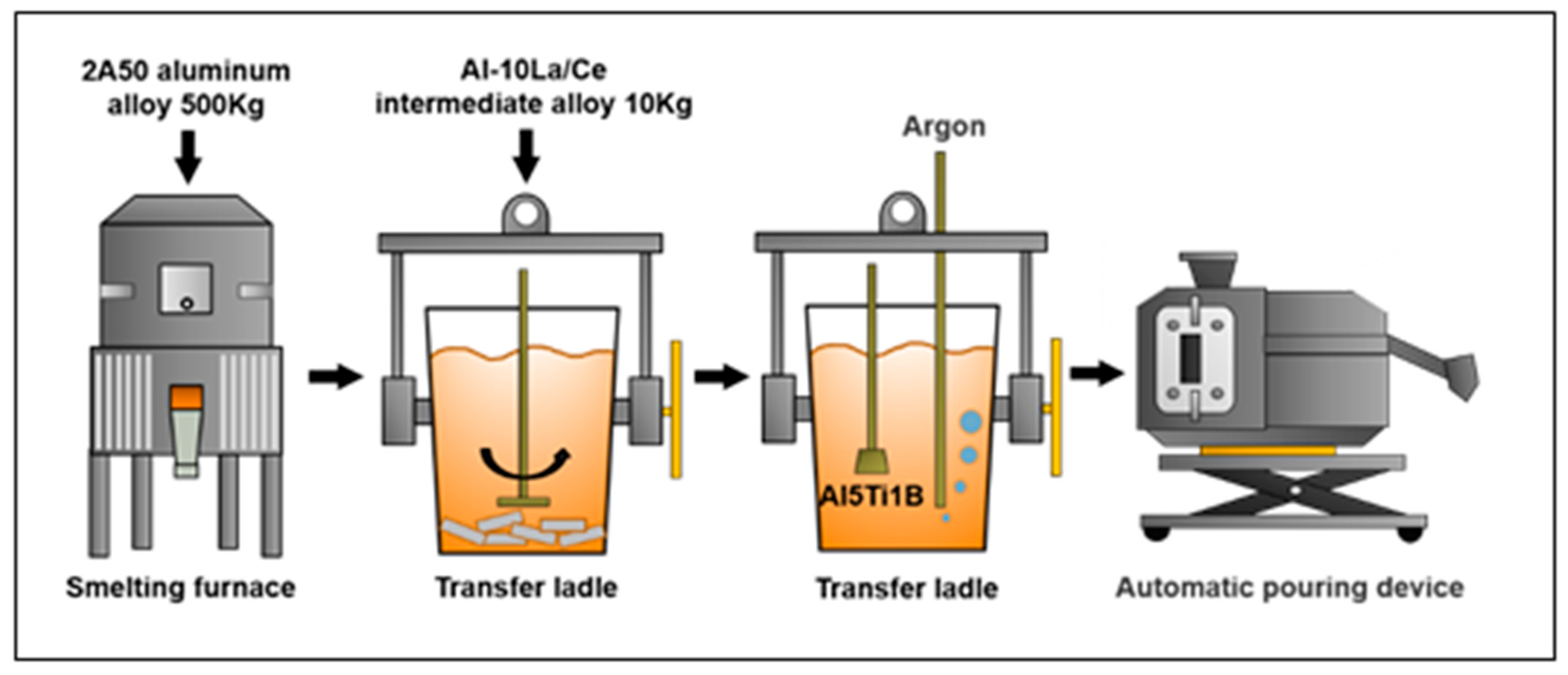
Figure 1. Schematic illustration of smelting steps.
Applsci 15 09478 g001
Figure 2. (a) Schematic diagram of die of MMDF for wheel hub: 1—upper die base; 2—upper pattern plate; 3—backing plate; 4—external punch; 5—internal punch; 6—external die sleeve; 7—bottom die; 8—lower die base; 9—upper connecting bolt; 10—connecting bolt; 11—stay bolt; 12—plunger piston; 13—wheel hub casting; 14—connecting bolt; 15—connecting bolt; 16—ejector pin; 17—foundation bolt; (b) MMDF process.
Applsci 15 09478 g002
Figure 3. Casting and sampling position diagram. (a) The cross-section of the casting. (b) Top view of casting.
Applsci 15 09478 g003
Figure 4. Micro-solidified structure under pressure: (a,e) E(α+Al2Cu); (b,f) Q (Al5Cu2Mg8Si6); (c,g) φ(AlxTi9La2Ce6Cu); (d,h) θ(Al2Cu).
Applsci 15 09478 g004
Figure 5. The optical microscope pictures of the bottom of the wheel hub at 118 MPa, “e” is the irregular eutectic, “f” is the oversintering structure, “g” is the remelting sphere: (a) as-cast structure; (b) solution temperature of 480 °C; (c) solution temperature of 510 °C; and (d) solution temperature of 540 °C.
Applsci 15 09478 g005
Figure 6. Variation curve of eutectic fraction with solution temperature.
Applsci 15 09478 g006
Figure 7. Eutectic structure (α+Al2Cu) at the grain boundaries, “c” is the eutectic structure: (a) definition of the irregular eutectic; (b) solution temperature of 480 °C; (c) solution temperature of 510 °C.
Applsci 15 09478 g007
Figure 8. Curve of plate eutectic width and spherical eutectic radius with solution temperature.
Applsci 15 09478 g008
Figure 9. The second-phase θ(Al2Cu) and φ(AlxTi9La2Ce6Cu) in α-Al: (a) definition of the second-phase; (b) solution temperature of 480 °C; (c) solution temperature of 510 °C.
Applsci 15 09478 g009
Figure 10. The size and spacing of the second phase vary with the solution temperature.
Applsci 15 09478 g010
Figure 11. A schematic diagram of the solution process of Al-Cu3-Si-Mg alloy under MMDF: (a) as-cast; (b) initial solid-solution stage; (c) final solid-solution stage; (d) complete solid-solution.
Applsci 15 09478 g011
Table 1. Composition of heat treatment samples (wt%).
CuSiMgMnTiFeLa/CeAl
2.40.80.560.50.0730.10.15Bal
Table 2. Different solution temperature schemes.
Serial NumberSolid-Solution Treatment
Heating Temperature/°CHolding Time/min
148030
249530
351015
451030
551045
651060
752530
854030
Table 3. Average diameters of each phase.
PhaseAverage Grain Size/Diameter (μm)
E(α+Al2Cu)2.5~3
Q (Al5Cu2Mg8Si6)2~2.5
φ(AlxTi9La2Ce6Cu)25~30
θ(Al2Cu)1~2
Disclaimer/Publisher’s Note: The statements, opinions and data contained in all publications are solely those of the individual author(s) and contributor(s) and not of MDPI and/or the editor(s). MDPI and/or the editor(s) disclaim responsibility for any injury to people or property resulting from any ideas, methods, instructions or products referred to in the content.