Article

Stiffness and Lightweight Enhancement in Biomimetic Design of a Grinding Machine-Tool Structure

Department of Mechanical and Computer-Aided Engineering, National Formosa University, Yunlin 63201, Taiwan
*
Author to whom correspondence should be addressed.
Appl. Sci. 2025, 15(17), 9449; https://doi.org/10.3390/app15179449
Submission received: 19 July 2025 / Revised: 17 August 2025 / Accepted: 26 August 2025 / Published: 28 August 2025
(This article belongs to the Section Mechanical Engineering)

Abstract

As global manufacturing faces rising energy costs, environmental pressures, and machining precision, the development trends of the machine tools are moving towards lightweight and high-rigidity structures. While those approaches of increasing key component geometrical size or enhancing rib design do enhance rigidity performance, they also usually increase weight, which conflicts with the goals of achieving high performance and environmental sustainability. Therefore, how to achieve system lightweightness while maintaining or enhancing structural rigidity has become a key research challenge. This study adopts a biomimetic design approach, drawing inspiration from the natural growth features of biological structures. By integrating these natural structural features, the design aims to enhance rigidity while reducing weight. Static and modal analyses are conducted firstly by using FEM software to simulate the total deformation, natural frequency, and modal shape, respectively. The biomimetic designs are then performed on those subsystems in a grinding machine-tool, which exhibit larger deformation and weaker stiffness by incorporating the structural features of leaf veins, cacti, and bamboos. Single or multiple structural feature combinations are constituted during the biomimetic design processes for worktable, base, and column subsystems, and the natural frequencies and weight obtained from the numerical analysis were compared subsequently to identify the better bionic subsystems that replace the corresponding ones originally assembled in the grinding machine-tool finally. The results show that one of the first three mode natural frequencies of a better bionic worktable (leaf vein and cactus) is increased up to 7.07%, with a 1.12% weight reduction. A better bionic base (leaf vein) with corner trimming exhibits a 14.04% increase in natural frequency and a 2.04% weight reduction. Similarly, a better bionic column (bamboo) achieves a 5.58% increase in natural frequency and a 0.14% weight reduction. After these better bionic subsystems are substituted in the grinding machine-tool, one of the first three mode natural frequencies is increased up to 14.56%, the weight is reduced by 1.25%, and the maximum total deformation is decreased by 39.64%. The maximum total deformation for the headstock is reduced by 26.95% after the original grinding machine-tool is replaced by better bionic subsystems. The increases in the specific stiffness for these better bionic subsystems are also investigated in this study to illustrate the effectiveness of the biomimetic designs.

1. Introduction

As global energy costs rise and environmental awareness increases, particularly in the manufacturing sector, there is growing pressure to improve energy efficiency and reduce environmental impact. Machine tools consume a significant amount of energy during operation, especially in the movement of mechanical components. Moreover, with the advancement of high-speed precision machining technologies, the structural stiffness and vibration-damping capabilities of the machine tools have become even more critical for improving machining accuracy and extending service life. Therefore, integrating high stiffness and lightweight characteristics during the structure design phase to meet the demands of high-speed precision machining and low energy consumption has become a crucial challenge for the machine-tool industry. This involves not only the application of new materials but also the development and implementation of innovative structural design methods.
A major challenge in this performance enhancement process is how to reduce weight while maintaining or even promoting the structural stiffness and strength of the machine-tool. Traditionally, machine-tool stiffness improvement has relied on increasing the geometrical size and thickness of the components, such as by reinforcing rib designs. While effective in enhancing structural rigidity, this approach also adds weight to the machine-tool, which contradicts the goal of energy efficiency and structural performance. This limitation has led to the pursuit of novel rib design strategies that aim to enhance machine-tool performance through structural optimization without adding extra weight. In the field of machine-tool design and manufacturing, lightweight technologies have proven to be an effective way to reduce energy consumption and enhance production efficiency. These technologies include advanced methods such as topology optimization, structural bionics, shape or sizing optimization, and system integration design, which aim to reduce the weight of machine-tool components while maintaining their mechanical performance. This not only reduces energy demands during manufacturing but also helps lower operational energy consumption.
The study conducted by Li et al. [1] proposed a method that applies the self-optimal growth principle of plant branching systems in nature to design the internal stiffener layout of large machine tools. The potential of leaf vein structures as conceptual generators for creating optimal load-bearing topologies in machine-tool structures was validated through numerical investigations. Based on this, an evolutionary algorithm was developed, in which three growth strategies were employed to determine whether candidate stiffeners should grow or atrophy according to the applied loads. It was found that leaf venation is a type of compliance-effective structure with a branching pattern. Its geometric and mechanical characteristics were identified through numerical studies as having significant potential for innovative application in stiffener layout design for machine tools. The stiffness enhancement was verified through both numerical analysis and experimental testing, and therefore, the proposed growth-based method was considered as a suitable choice for the design of eco-efficient machine tools. Gao et al. [2] developed a new machine-tool stiffness model, based on the analysis of the machining space, to optimize the machine-tool structure design and layout, thereby improving machining quality and predicting machining errors. The approach involved decomposing the machine-tool into multiple components and modeling the stiffness of each component separately. Then, using a synthesis method, these individual stiffness models were combined into an overall machine stiffness model to predict the machining errors of the entire machine-tool. Experimental results showed that the proposed stiffness model could effectively predict the stiffness of the machine-tool at different machining positions and could be used to evaluate and reduce machining errors during the processes. This model improves the efficiency of machine-tool structure and layout design and holds practical application potential for future manufacturing processes. Revanasiddesh et al. [3] investigated the modal parameters of CNC lathes to investigate the dynamic behavior of the machine-tool and improve its performance. The finite element method was used to simulate the CNC lathe and predict its modal characteristics, including natural frequency, damping, and mode shapes. The CNC lathe was then struck with a hammer, and its response was measured to obtain experimental modal parameters. The results from finite element simulations and experiments were compared. The experimental results showed that the proposed FEM simulation and modal analysis exhibited good consistency with the experimental results. Gao et al. [4] used Ansys software to perform static and modal analyses on the worktable, followed by topology optimization. A 3D model of the worktable was created by SolidWorks, and the static and modal analyses were conducted in Ansys Workbench. Then, structural optimization was carried out on the worktable in the topology optimization module of Ansys Workbench to improve its performance. The experimental results showed that the worktable after topology optimization improved its dynamic performance while maintaining the original static performance and reducing its weight. Zhao et al. [5] studied the use of structural biomimetics, based on the structural principles of biological skeletons and sandwich stems, to design a machine-tool column with internal reinforcing ribs. FEM simulations were conducted using Ansys software to compare the differences between the original and biomimetic designs in terms of static displacement and dynamic performance. The experimental part involved manufacturing a scaled model using selective laser sintering (SLS) technology, followed by static and dynamic testing. The experimental results showed that the bionic column reduced the maximum static displacement, decreased its mass, and improved the first two natural frequencies, indicating that the biomimetic design was effective in improving the static and dynamic structural performances of the high-speed machine tools. Xing et al. [6] studied the optimization of the structural design of a high-speed machine-tool worktable by applying the distribution principles of leaf veins, aiming to reduce the weight of the worktable while enhancing its rigidity. Statistical and FEA were used to explore the mechanical effects and structural benefits of leaf veins, which were then applied to the design of the worktable. FEA and experimental verification were performed to assess the effectiveness of the design. The experimental results showed that the biomimetic design of the worktable reduced the average displacement, and the average displacement in experiments was also decreased, proving the effectiveness of the biomimetic design. Zhao et al. [7] aimed to find innovative solutions for lightweight mechanical design through the application of structural biomimetics, particularly exploring the structural features of giant waterlily leaf ribs and cactus stems, and applying them to the design of the gantry machining center. By mimicking similar network structures found in nature, a bionic model was created, which showed better load-carrying capacity compared to the original distribution. Reinforced ribs in parallel or vertical configurations were adjusted to reduce weight while maintaining or enhancing structural rigidity. The results showed that the specific stiffness of the bionic model was increased, the maximum static deformation was decreased, the weight was reduced, and the first four natural frequencies significantly improved, demonstrating the effectiveness of the structural biomimetic design. Gao et al. [8] conducted a structural biomimetic design for the machine-tool columns, aiming to improve the performance of mechanical components, especially in terms of enhancing static and dynamic performance, by mimicking the distribution features of the leaf veins. Based on the features of leaf vein structures, the internal configuration of the stiffening ribs in the column was adjusted to improve the overall structural load-bearing efficiency and reduce weight, while ensuring manufacturability. The results showed that, compared to the original column, the bionic column reduced the maximum deformation, and the natural frequencies of the six modes were increased to different extents. Liu et al. [9] aimed to improve the design of the column in a gantry machining center by using a biomimetic design method to enhance its static and dynamic performance, by designing the stiffener plates of the column based on the structural configuration of the ginkgo root system. The distribution principles of the ginkgo root system were applied to design the stiffener plates, with the goal of achieving structural lightweightness and enhancing anti-vibration performance. These designs were modeled in CAD software and simulated using Ansys software for FEA. Experimental results showed that the bionic column design reduced its weight while increasing the first five natural frequencies. The experimental results confirmed the correctness of the biomimetic design method and verified the improvements in the structural design. Li et al. [10] investigated how to use the macroscopic and microscopic features of bamboo for the biomimetic design of the CNC boring and milling machine-tool columns, aiming to improve the structural efficiency of the column and reduce material redundancy. The initial design of the column was cylindrical, and optimization was carried out based on the relationship between the number of transverse ribs and the whole bending deformation. Further optimization was achieved by designing and adjusting the transverse rib configuration based on inspiration from the bamboo joint node structure. The outer profile of the A-type column is an octagonal cross-section with a circular hollow structure inside, while the B-type column features a chamfered rectangular hollow structure with similar inner and outer profiles. The results showed that the specific stiffness of the B-type column increased, and its overall performance outperformed the A-type column. The final choice was the B-type as the final bionic structure. FEA results showed that the maximum displacement of the B-type column was decreased, and its specific stiffness was increased. Gao et al. [11] investigated the design of an aluminum alloy honeycomb structure for the worktable of a high-speed machine-tool, aiming to reduce the weight of the worktable and thus minimize the inertial forces generated by rapid movements to improve machining accuracy. Ansys Workbench was used for static and modal analyses to compare the performance of the new structural worktable with the original worktable. This study focused on structural improvement by incorporating lightweight aluminum alloy honeycomb structures inside the worktable to reduce the overall weight and inertial forces, thus enhancing structural performance. The results showed that the weight of the honeycomb structure worktable was reduced as compared to the original structure, with smaller static deformation, indicating better static characteristics. Modal analysis results showed that the natural frequencies of the improved worktable were higher, indicating better dynamic characteristics. Jiao et al. [12] explored the lightweight design of a low radar cross-section (RCS) pylon based on structural biomimetics. The aim of this study was to improve the specific structural efficiency (SSE) of the pylon, thereby reducing its weight and enhancing its properties. FEA was conducted, along with static, dynamic, and electromagnetic tests to analyze the properties of both the original and bionic pylons. The characteristics of the bionic pylon were verified by comparing the displacement, stress, and weight of the original beam and the bionic beam based on plant structural features. The design process included requirements identification, analysis, and experimental validation. The experimental results showed that the bionic pylon improved the specific strength efficiency and specific stiffness efficiency, and significantly reduced the RCS. These results demonstrate the effectiveness and potential of structural biomimetics in designing low-RCS pylons. The biomimetic design not only significantly reduced the weight but also improved the overall structural characteristics. Zhang et al. [13] conducted a study on the bending characteristics analysis and lightweight design of a bionic bamboo structure beam. The structure was inspired by the natural features of bamboo, particularly its light weight and high strength. A bending model of the bionic bamboo beam was developed and validated using FEM. For the lightweight design, the response surface method was used for structural optimization. Experimental results showed that the optimized bionic bamboo beam was lighter than the hollow beam and also lighter than the solid beam, with excellent bending resistance. The bending resistance was 234% of the hollow beam and 271% of the solid beam. The bionic structure also outperformed the original structure in energy absorption characteristics, and the 12-hole structure performed better than the 13-hole structure. This study offers a new approach to improving artificial structures based on natural structures and has significant implications for the development of lightweight and high-strength energy-absorbing devices. Xing et al. [14] used structural bionics to perform a lightweight design for an aircraft reinforcing frame. First, the structural features of peltate venation and root architecture were analyzed, and then these features were used to develop a frame design model. FEA was conducted to assess the properties of different design options, and the optimized design was selected to achieve lightweight goals. Experimental results showed that the bionic method designed frame reduced the total weight by approximately 6.0% while maintaining stiffness and strength. Additionally, this study found that the bionic frame exhibited lower maximum displacement and stress under shear and bending conditions as compared to the conventional frames. Yan et al. [15] studied how to improve the rigidity and lightweight properties of machine-tool structures through biomimetic design, particularly by mimicking adaptive growth phenomena in nature to optimize the layout of reinforcement ribs. A mathematical model was first established theoretically to support the adaptive growth of reinforcing plates under applied loads, followed by the development of algorithms to generate the reinforcement rib layout. Experimental results showed that the new reinforcement rib layout through biomimetic design significantly enhanced the rigidity of the machine-tool bed, demonstrating the applicability and effectiveness of this method. Liu et al. [16] conducted a study on the structural biomimetic design of a machine-tool table, employing four types of bionic structures: namely, bamboo cross-section bionic structure table, spider web bionic structure table, honeycomb bionic structure table, and prairie rushes bionic structure table. Finite element simulations were used to perform static and modal analyses. Furthermore, the entropy-weight TOPSIS method was applied to evaluate the four bionic structures, and based on these results, a multi-objective optimization design was carried out. The results indicated that the prairie rushes bionic structure was identified as the optimal design. As compared to the original table, the bionic structure reduced mass, increased the first natural frequency, reduced maximum displacement, and significantly lowered the maximum equivalent stress. Wu et al. [17] investigated a novel bionic energy absorber based on a tree-like fractal approach. These structures are inspired by the branch distribution in nature, and fractal design is used to optimize the energy absorption efficiency of the structure. First, based on the tree-liked fractal method, tree-like structures with fractal geometric features were designed. Then, FEM and experimental tests were used to evaluate the performance of these structures, and structures were optimized to achieve better energy absorption efficiency. The experimental results showed that this study offers a new design concept that effectively develops lightweight and high-efficiency energy absorbers. In particular, by adjusting the fractal order and wall thickness distribution, the energy absorption and impact stability of the structure can be significantly improved. Furthermore, comparative studies show that the third-order fractal structure outperforms the original structure in terms of energy absorption and structural stability. Zhang et al. [18] aimed to optimize the distribution of internal stiffeners in a machine-tool base structure by mimicking the growth mechanism of biological branching systems in nature to improve overall structural stiffness and lightweight design. The study used the adaptive growth method, a biomimetic topology optimization technique, to optimize the distribution of stiffeners in a box structure. The experiment mainly focused on the topological optimization of the internal stiffener distribution, including rib growth, branching, and degradation, to seek the optimal structural layout under given loading and support conditions. Furthermore, based on the optimal stiffener distribution design, structural dimension optimization was performed to achieve the lightweight design goal. The experimental results showed that the optimized structure improved both dynamic and static characteristics, significantly reduced the weight as compared to the initial structure, and enhanced the rigidity of the machine bed structure, with a more reasonable rib layout. Cai et al. [19] proposed a new topology optimization method designed specifically for materials subjected only to tensile or compressive forces, based on bone remodeling theory to find the optimal topology for structures. The method uses reference interval and material replacement methods, simplifying the optimization processes through FEM. This method first replaces the original material subjected to only tensile or compressive forces with an equivalent isotropic material, then calculates the effective strain energy density to update design variables. The results showed that this new method can significantly reduce the computational cost of structural analysis while maintaining the accuracy of the analysis. Ji et al. [20] investigated how to optimize the internal stiffener layout in three-dimensional box structures based on the natural branching phenomenon, with the aim of enhancing the overall stiffness and durability of the structure. First, a basic model of the three-dimensional box structure is established, including both solid and shell elements. The thickness and position of the reinforcements are then updated through iterative formulas, based on minimizing the structural stress or strain energy. The results show the effectiveness of this method through several typical design examples, including designs under both single and multiple loading conditions. The application of the natural branching growth approach can significantly improve the mechanical properties of the structure. Zhao et al. [21] investigated the application of structural bionic methodology in the lightweight design of mechanical structures. The primary objective was to develop a standard methodology for dead-load reduction and performance improvement in bionic mechanical structures. By transferring structural principles from nature into technical construction, the goal was to achieve maximum structural efficiency from minimal resources. The research process included extracting structural principles from natural models, performing simulation tests using the FEM, and constructing and testing models using various fabrication techniques. The results showed that the bionic models were lighter but stiffer than the original ones. This demonstrated that structural biomimetic design can effectively update traditional design concepts, achieve maximum structural efficiency, and verify that structural bionics can serve as a systematic theory and standard methodology in mechanical structure design. Li et al. [22] developed a new topology optimization solution based on the morphology of plant ramifications, aiming to provide designers with feasible stiffener layout options for the interior of large-scale garbage truck containers. An evolutionary algorithm is used to simulate the growth process of the stiffening rib layout. This process does not require a dense ground structure, nor does it require modifications to existing FE software, making it fast, easy to apply, and virtually unconstrained. Experimental results show that the method effectively provides a stiffening rib layout with a uniform stress distribution.
In the field of engineering design, biomimetic design methods have been proven to improve the dynamic characteristics of the machine tools and enhance structural rigidity and durability without adding extra weight. Current research is mainly focused on applying a single biological structure to optimize machine tool components, such as using leaf vein structures to design high-rigidity worktables, strengthening the gantry machining center’s beams using the features of cacti and giant water lily structures, and enhancing the compressive properties of columns using bamboo joint structures. However, research that integrates two or more different biological structural features into a single part structure design simultaneously is still under development, and its potential for industrial applications, such as machine-tool, has not yet been fully realized. Therefore, this study proposes a comprehensive biomimetic design method that combines the structural features of the leaf veins, cacti, and bamboos to fill this research gap. The goal is to provide significant advantages in improving structural rigidity and lightweight design, offering a more comprehensive and efficient solution for machine-tool design. This study not only demonstrates the potential application of biomimetic design in machine-tool components but also lays the foundation for further integration and application in the future.
In order to meet the dual goals of high stiffness and lightweightness at the same time, this study aims to develop an innovative rib structure design method that seeks to achieve an optimal balance between high rigidity and lightweight construction. These designs aim not only to reduce unnecessary material usage-thereby lowering the overall weight and energy consumption of the machine-tool, but also to enhance the machining accuracy and speed. Specific strategies include employing various forms and configurations of reinforcement ribs to meet the specific mechanical and dynamic requirements of high-speed precision machining.
2. Biomimetic Design Basis

“Bionics” is a discipline that involves designing and meeting human needs by mimicking the forms and structures of living organisms. This design inspiration comes from nature and can be seen in many everyday products, including jewelry, furniture, and even architectural structures. In these designs, people not only imitate the appearance of nature but also draw inspiration from it, transforming it into practical product elements.
According to the literature study, modern biomimetic design can be divided into morphological biomimicry, functional biomimicry, visual biomimicry, and structural biomimicry. A brief explanation is as follows: (1) morphological biomimicry design, which studies the appearance and symbolism of biological and natural substances (e.g., animals, plants, etc.), incorporates these elements into design through artistic methods. (2) Functional biomimicry design, which focuses on studying the functional principles of biological and natural substances, uses these principles to improve existing technologies or develop new technologies, advancing new product research and development. (3) Visual biomimicry design studies the recognition of images and the analysis and processing of visual signals by biological visual organs and is widely applied in product design, visual communication design, and environmental design. (4) Structural biomimicry design, which studies the internal structural principles of biological and natural substances and their application in design, is primarily used in product design and architectural design, particularly in the study of stems, leaves, animal forms, muscles, and skeletal structures.
Biomimetic design is a methodology that mimics the structures, functions, and evolutionary mechanisms of organisms in nature to solve engineering problems and promote innovative design. Its core idea is that biological structures and behavioral patterns, which have formed through billions of years of evolution, are often highly optimized in terms of functionality and resource efficiency. Therefore, translating the operational mechanisms of biological systems into engineering solutions can not only enhance design performance but also guide human technology development toward sustainability and energy efficiency.
Based on current research in bionics and design engineering, the implementation of biomimetic design in practice must follow several key principles to ensure its scientific soundness and practicality. The main principles are as follows: (1) functionality matching, i.e., the foremost prerequisite in biomimetic design is the accurate identification of the functional mechanisms of biological systems and their correspondence to the functional requirements of engineering problems. (2) Structure–function consistency, i.e., effective biomimetic design must maintain the consistency between biological structures and their corresponding functions. When substituting materials or altering manufacturing processes, it is essential to preserve critical geometric features and logical mechanisms. (3) Scaling law consideration, i.e., biological systems have mostly evolved at the micro scale, whereas engineering applications often exist at much larger scales. Biomimetic design must consider how mechanical properties, force behaviors, and material characteristics change across different scales and apply appropriate transformations. (4) Integrated and systematic thinking, i.e., biomimetic design, should not be limited to individual components but should incorporate systems thinking by considering the integration of functions and multifunctionality of the entire product or system. (5) Manufacturability and material adaptation, i.e., biomimetic design, must take into account the feasibility of current manufacturing capabilities and material characteristics. This helps to avoid overly idealized or impractical design concepts. Therefore, engineering constraints and material selection criteria must be considered from the outset of the design process.

3. Biomimetic Design Approach

In industrial design, developing an impact-resistant and low-vibration machine-tool structure is essential, requiring the reduction of vibration and cutting fluctuation while decreasing weight and increasing rigidity. Biomimetics, which draws design inspiration from nature, has been proven effective in solving technical challenges and promoting sustainable development. By applying the numerical simulations of the static and modal analyses, the torsional and bending deformation modes of the structure are investigated to identify the weaker stiffness or critical areas. These areas are then improved through biomimetic redesign modifications inspired by natural structures. By selectively removing the less critical areas that do not significantly affect rigidity and reinforcing those weaker stiffness areas, an optimal balance between lightweight construction and high rigidity may be achieved, ensuring overall structural integrity and stability of the entire system. The relevant numerical analyses and biomimetic design approach are illustrated as follows:

3.1. FEA Modeling

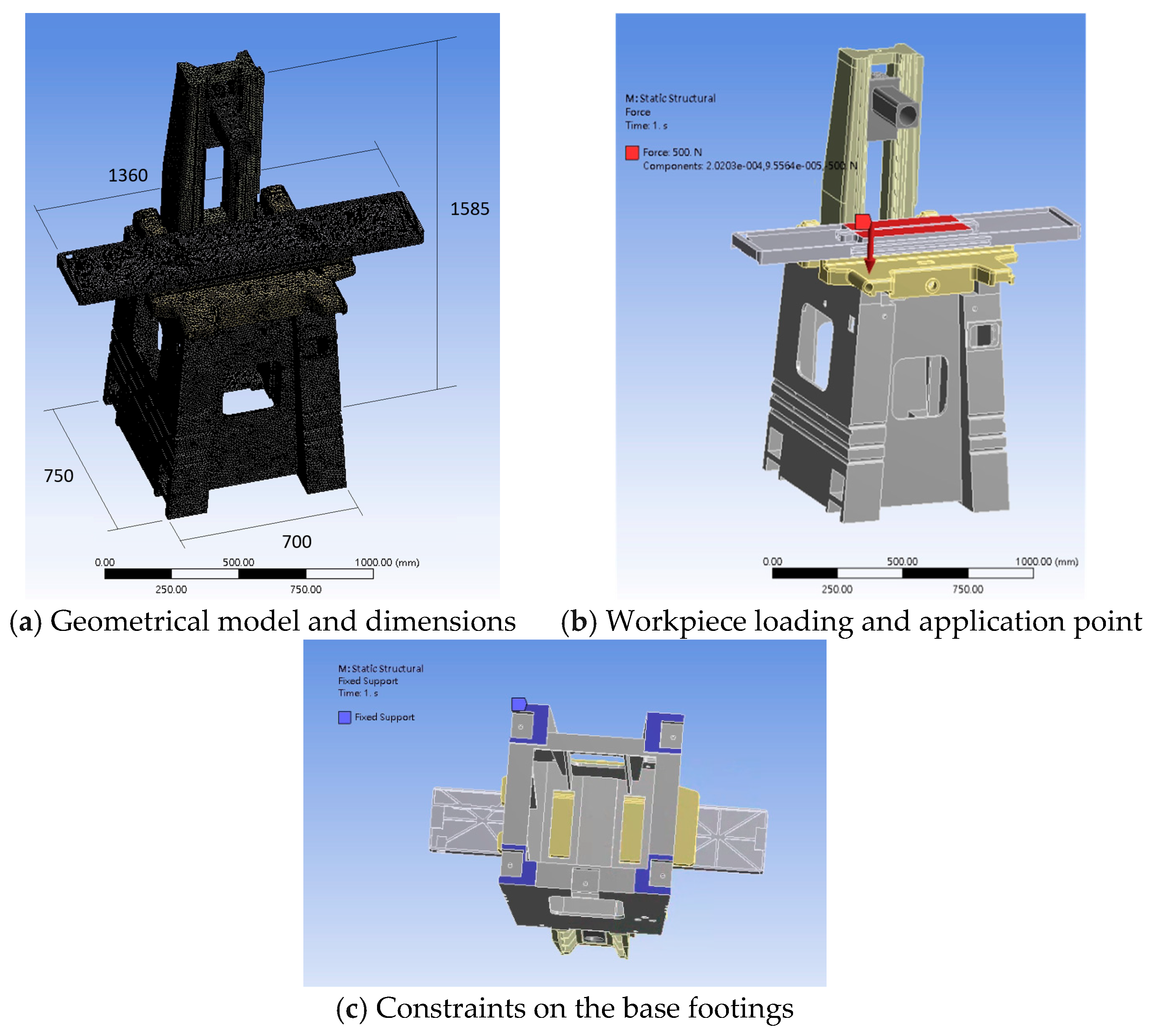
FMA for static and modal simulations was carried out by the finite element software Ansys Workbench in this study. Figure 1 shows the dimensions of a 3D geometrical model, gridded pattern, and boundary conditions for numerical analyses of a grinding machine-tool. The materials used for the key subsystems, headstock, column, worktable, saddle, and base, of a grinding machine-tool are all FC30 cast iron with different heat treatments, and their properties are shown in Table 1. The tetrahedral element was used for FE mesh with program control, and its mesh size, number of elements, and nodes in the analyses are shown in Table 2, which were determined from the convergence analysis as mentioned below. The applied loads are the weight loadings of the machine-tool itself and the workpiece, which were applied on the central surface zone of the base subsystem, and all degrees of freedom of the footings of the base subsystem are constrained. While the modal extraction method is Block Lanczos, the number of modes extracted is 15 in the modal analysis in this study.
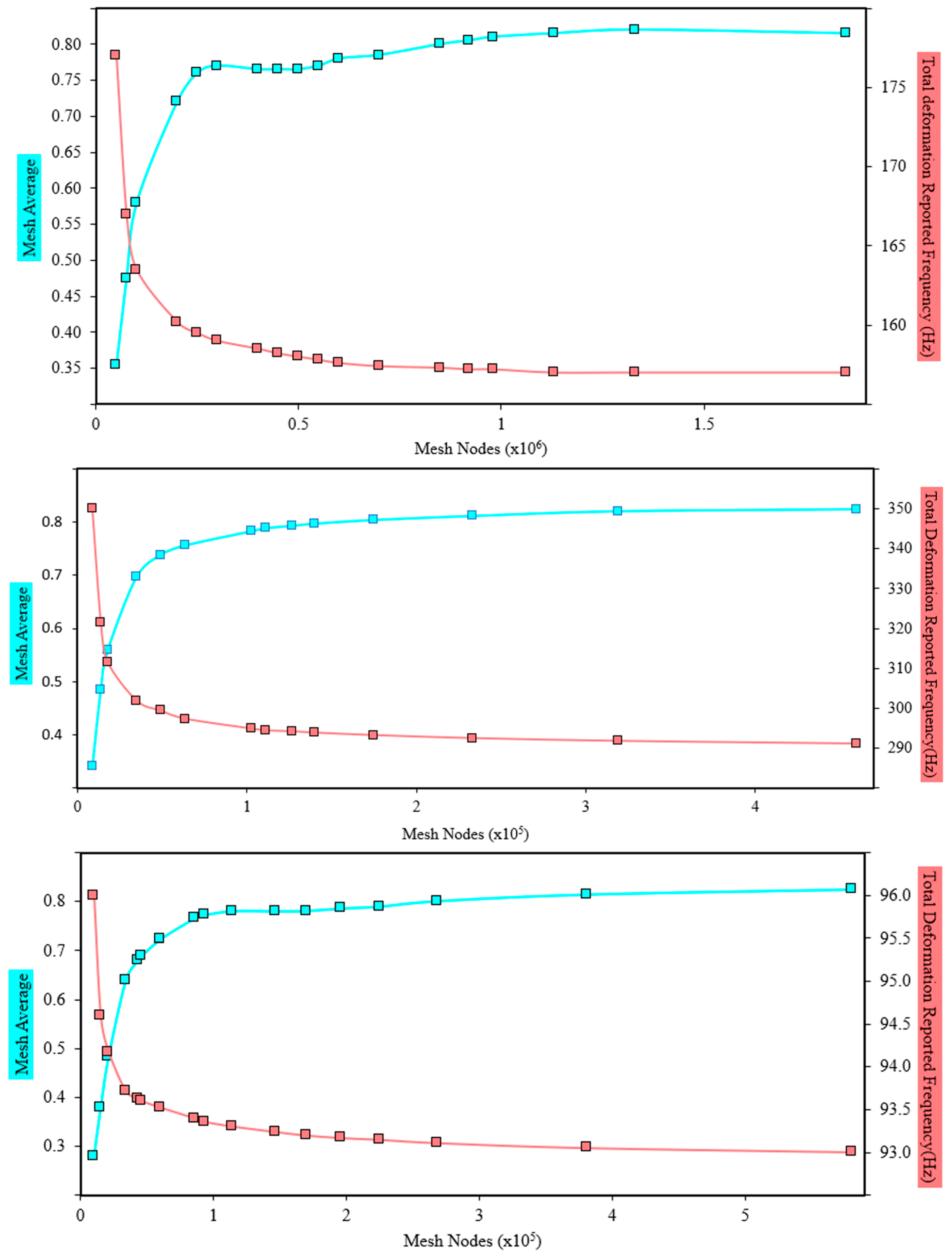
In order to ensure the stability of the FMA results, it is necessary to carry out a convergence analysis to find out the suitable element mesh size for different FE models of the system. In ANSYS Workbench 18.1, the tetrahedral element is always selected in the finite element mesh of the model, and the body sizing may be gridded sequentially in a descending manner (element size from 50 mm to 10 mm in this study), and the related parameters of Mesh-Average and mesh nodes are deduced accordingly. Furthermore, the convergences of the 1st mode natural frequency results and the Mesh-Average associated with different element sizes are always noted as an index for mesh convergence judgment. The Mesh-Average parameter in the software for element mesh quality index is finally integrated as the basis for the selection and examination of a suitable element size fulfilling convergent demand.
Figure 2 shows the relationship among Mesh-Average, 1st mode natural frequency, and number of nodes for the base, column, and worktable subsystems, respectively. When the element mesh size is smaller than a certain size, the analysis results will begin to stabilize; that is, the natural frequency difference of the 1st mode will begin to converge within a certain range. The tendency of Mesh-Average is also approaching a certain value simultaneously. The suitable element mesh size is different for the various volumes and construction of the part or subsystem, but the suitable mesh size and corresponding mesh nodes may be determined based on the parameter of Mesh-Average. Generally, it can be found that the natural frequency difference of all parts or subsystems of the whole machine-tool falls within 1% when the Mesh-Average approximately equals 0.8.
As mentioned above, the static analysis was conducted on a grinding machine-tool under the weight loadings of the machine-tool itself and the workpiece by FEM. The total deformation distributions for the entire machine-tool and its subsystems obtained from the analysis results are shown in Figure 3, in which the maximum total deformations of the entire machine-tool and its subsystems are shown in Table 3. Among them, the worktable exhibits the largest total deformation, reaching 0.045376 mm. This indicates that the greatest loading or stress was supported by the worktable within the machine-tool. The maximum deformation occurs at both ends of the worktable, which exhibits an uneven deformation phenomenon within this subsystem, as shown in Figure 3c. Moreover, the column and base subsystems are also significantly affected by this weight loading state, with the maximum deformation of the column occurring at the top surface, while the base experiences its largest deformation in the central zone of the base top. To enhance the overall structural rigidity and durability, structural reinforcement and redesign should be applied to these weaker areas, i.e., both ends of the worktable, the top surface of the column, and the central zone of the base top. Special attention should be given to strengthening the structural integrity and stability on both ends of the worktable, reinforcing the top surface of the column, and fortifying the central zone of the base top.
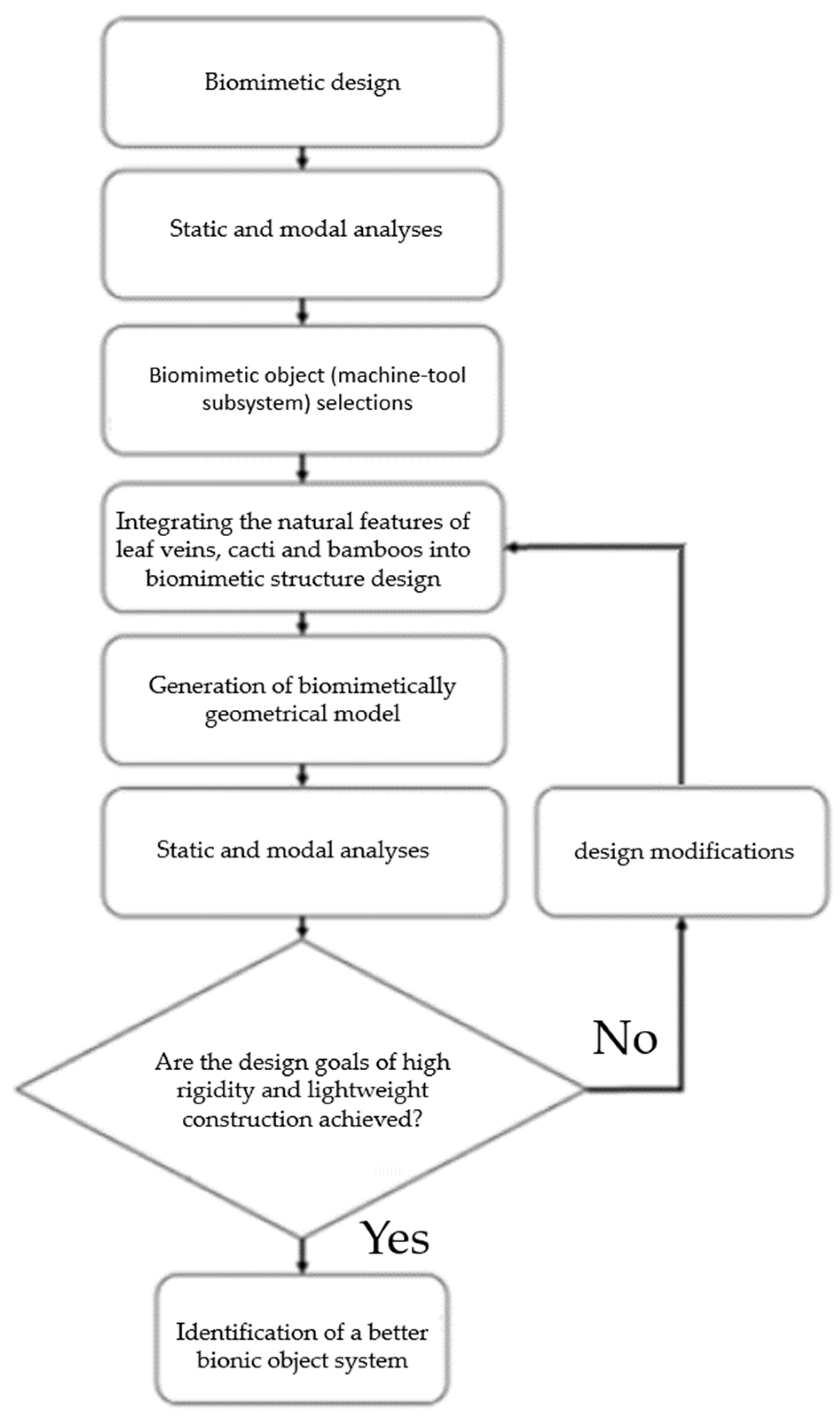
The static and modal analyses should be performed before and after the biomimetic designs. The former is for investigating the subsystems with larger deformations, and they were further selected as the biomimetic objects. While the latter is for comparisons of structural performance between various biomimetic designs, in which a better biomimetic design is identified, consequently, for the subsystem. That is, the biomimetic designs were performed on those subsystems in a grinding machine-tool, which exhibit larger deformation and weaker stiffness by incorporating the structural features of the leaf veins, cacti, and bamboos. By mimicking the structural features found in nature, such as the primary and secondary veins in leaves, the diagonal cross-structure and mesh-like skeletal distribution in Mexican cacti, and the joint nodes in bamboo, as shown in Figure 4, significant enhancements in structural performance may be achieved. These include efficient loading support and stress dispersion, improved load-bearing capacity, torsional and bending resistances, and enhanced compressive strength and vibration-damping properties, corresponding to the respective natural features. Together, these biomimetic features enable the development of more resilient and efficient engineering solutions. Single or multiple structural feature combinations are constituted during the design processes for worktable, base, and column subsystems, and the natural frequencies and weight were compared subsequently to identify the better bionic subsystems, which will substitute the corresponding ones originally assembled in the grinding machine-tool finally. However, if the dual goals of high rigidity and lightweightness are not satisfied during the biomimetic processes, the design modifications are conducted repeatedly until they are achieved. A flowchart for biomimetic design of a grinding machine-tool in this study is shown in Figure 5, and the details of the biomimetic design for these important subsystems are illustrated as follows.

3.2. Worktable Subsystem

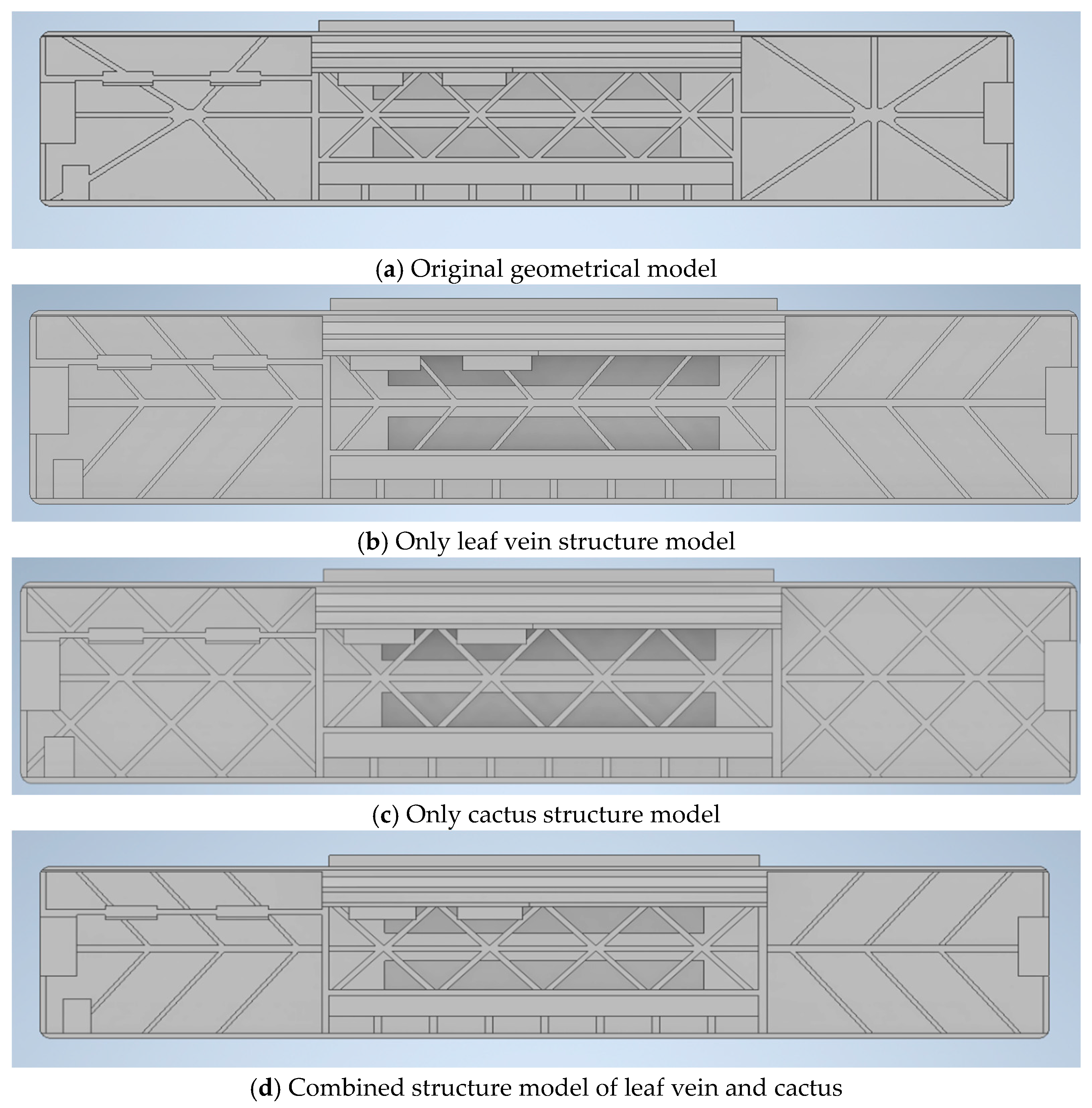
Based on the results of the static analysis, the maximum deformation of the worktable primarily occurs at both ends, as shown in Figure 3c. To enhance rigidity and reduce weight, the rib structure of the original model, as shown in Figure 6a, is redesigned by mimicking the natural features of organisms to enhance its structural performance. By reorganizing the rib design, the deformation in critical areas may be effectively reduced; thus, the overall rigidity and durability of the structure are promoted. This design enhancement not only improves the structural performance of the worktable but also extends its lifespan.
In this systematic process of design, analysis, and modification, a bionic rib model was created first by mimicking the leaf vein, featuring one primary rib and six secondary ribs to establish the fundamental structure, as shown in Figure 6b,d. Modal analysis is then conducted on the redesigned model to investigate its modal performance, with a particular focus on changes in the first three mode natural frequencies. By comparing the analysis results with those of the original model to identify which design modifications may effectively increase the natural frequencies. Based on the comparative results, a bionic model that exhibits the better natural frequency and lightweight construction relative to the original system is selected. Subsequently, the original subsystem in the grinding machine-tool is replaced by the better bionic subsystem, and the modal and static analyses are performed once again on this entire system model to validate its overall performance. This procedure aims to enhance the structural performance of the biomimetic designs by altering the arrangement and configuration of the ribs, and to ensure that these improvements may translate into a better overall machine-tool performance.
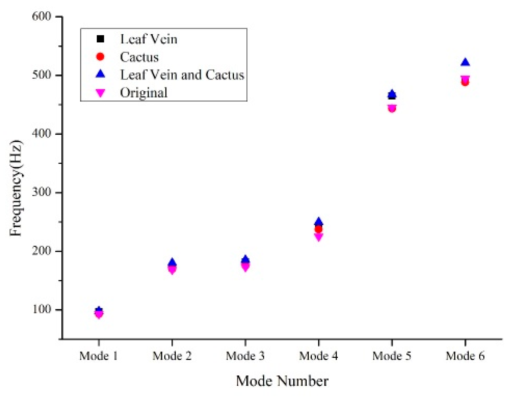
There are three rib design models for the worktable, i.e., a biomimetic rib based solely on the leaf vein structure as shown in Figure 6b, a rib based solely on the cactus structure as shown in Figure 6c, and a biomimetic rib combining the above two structures as shown in Figure 6d. Modal analyses are conducted on these biomimetic rib models, followed by a comparative assessment of their structural performances. Table 4 and Figure 7 show the comparisons of the first six mode natural frequencies among distinct biomimetic design models for the worktable subsystem. The natural frequency obtained from the analysis for the combined structure design is better than that of the single structure. Thus, a better bionic subsystem with a leaf vein and cactus combination is identified.
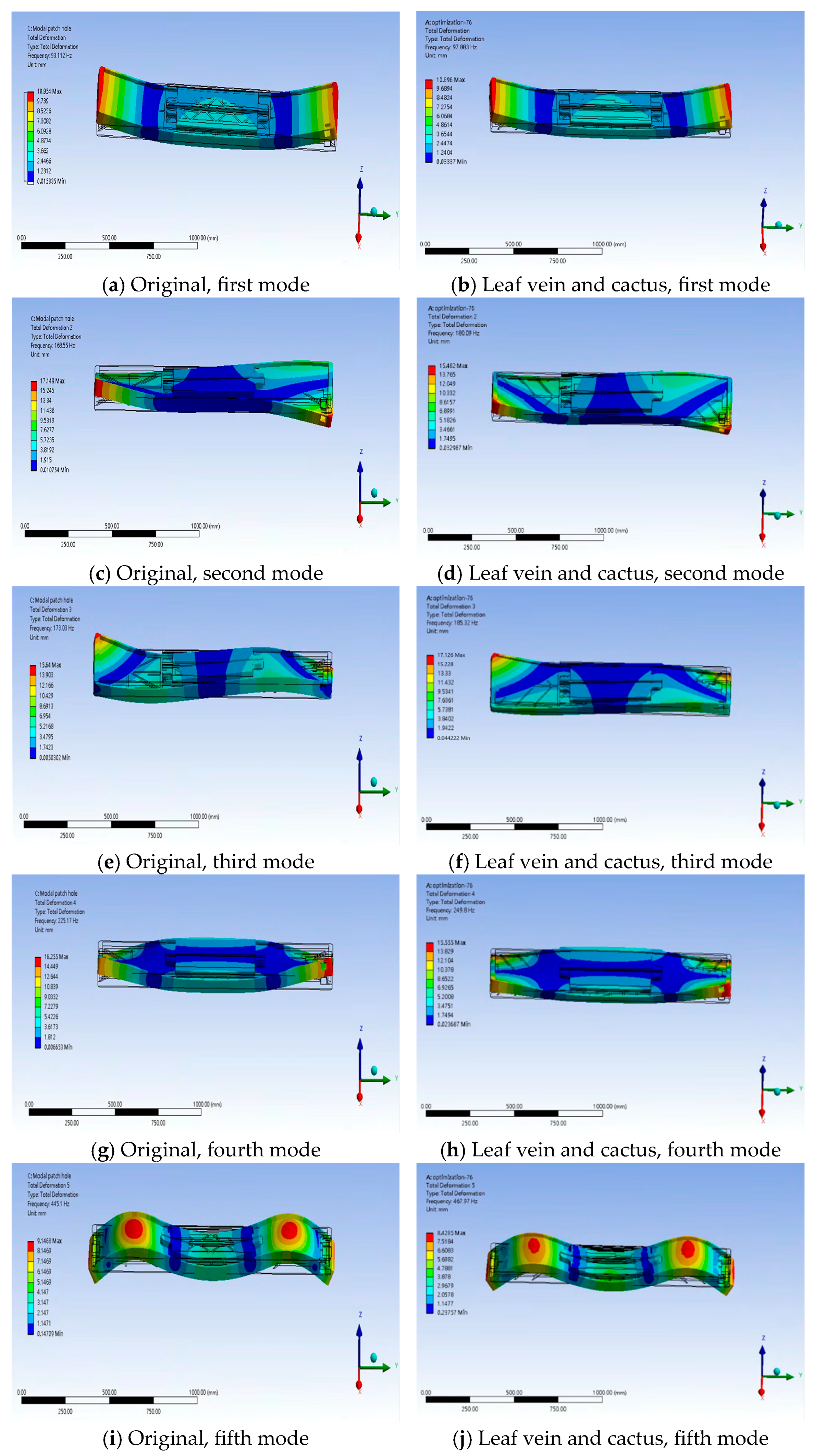
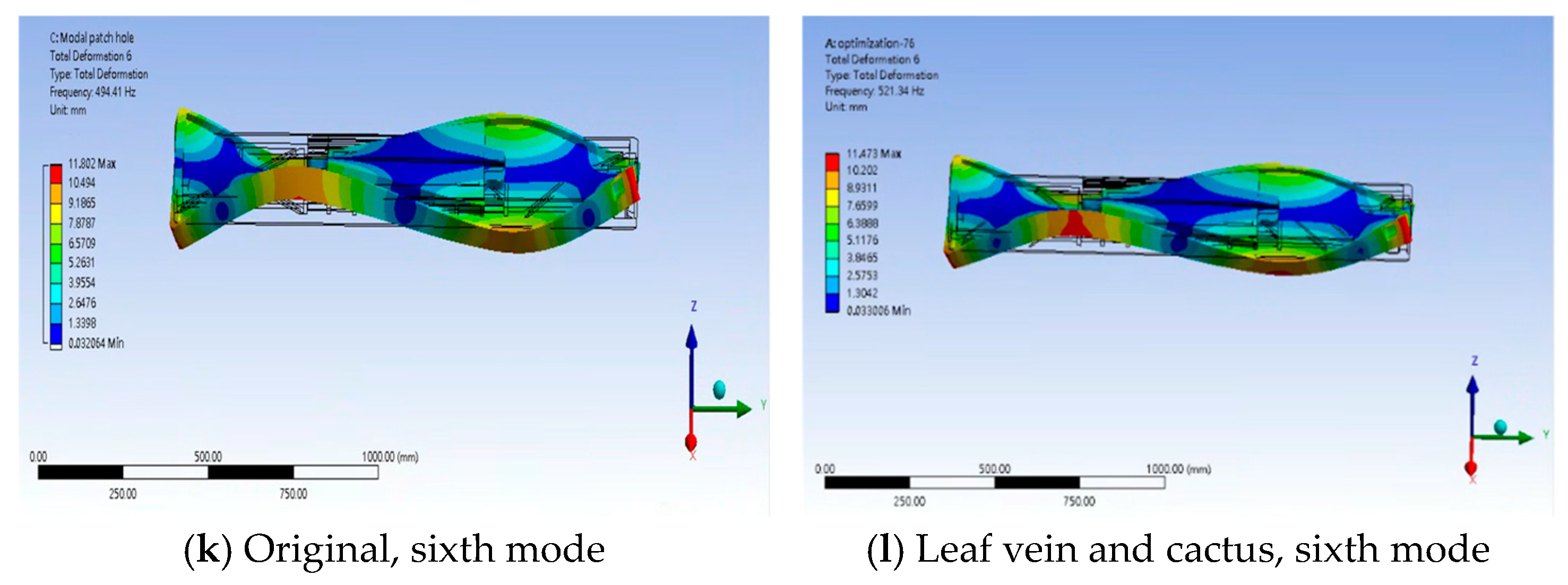
This study integrates leaf vein and cactus structures into a biomimetic design to enhance the structural performance of a grinding machine-tool worktable. The hierarchical planning of main and secondary leaf veins may effectively support the loadings, disperse the stresses, and reduce the deformation, while the cactus-inspired diagonal cross and mesh-like structures provide excellent torsional rigidity, improving overall structural stability. As compared with the original design, the better bionic rib design achieves a 1.12% weight reduction, as shown in Table 4, while enhancing both bending and torsional resistances. This rib design structure exhibits excellent bending resistance in the first modal shape, indicating enhanced stiffness and deformation resistance when subjected to bending moments primarily along the z-axis, as shown by the contrast in Figure 8a,b. This characteristic effectively reduces bending deformation under vertical loads, thereby improving overall structural stability and machining accuracy. Moreover, the second to fourth modal shapes reveal pronounced torsional resistance, suggesting that the structure possesses superior capability in withstanding torque along the y-axis, as shown by the contrast between Figure 8c,d, Figure 8e,f, and Figure 8g,h. This implies that under lateral loads or asymmetric loading conditions, the design can efficiently disperse torsional stresses and mitigate stress concentrations, ultimately enhancing the durability and reliability of the structure.
The overall rigidity enhancements, particularly the first three mode frequencies in the combined rib structure design, prevail over those of the other designs, although the weight is slightly greater than that design based solely on the leaf vein structure. Hence, this combined biomimetic approach may be regarded as a better bionic worktable from the overall assessments of rigidity enhancement and weight reduction. These findings confirm that biomimetic design not only offers an innovative strategy for structural performance tuning but also effectively balances lightweight construction with high rigidity, meeting the demands of high-speed precision machining equipment for reduced weight and enhanced stability.

3.3. Base Subsystem

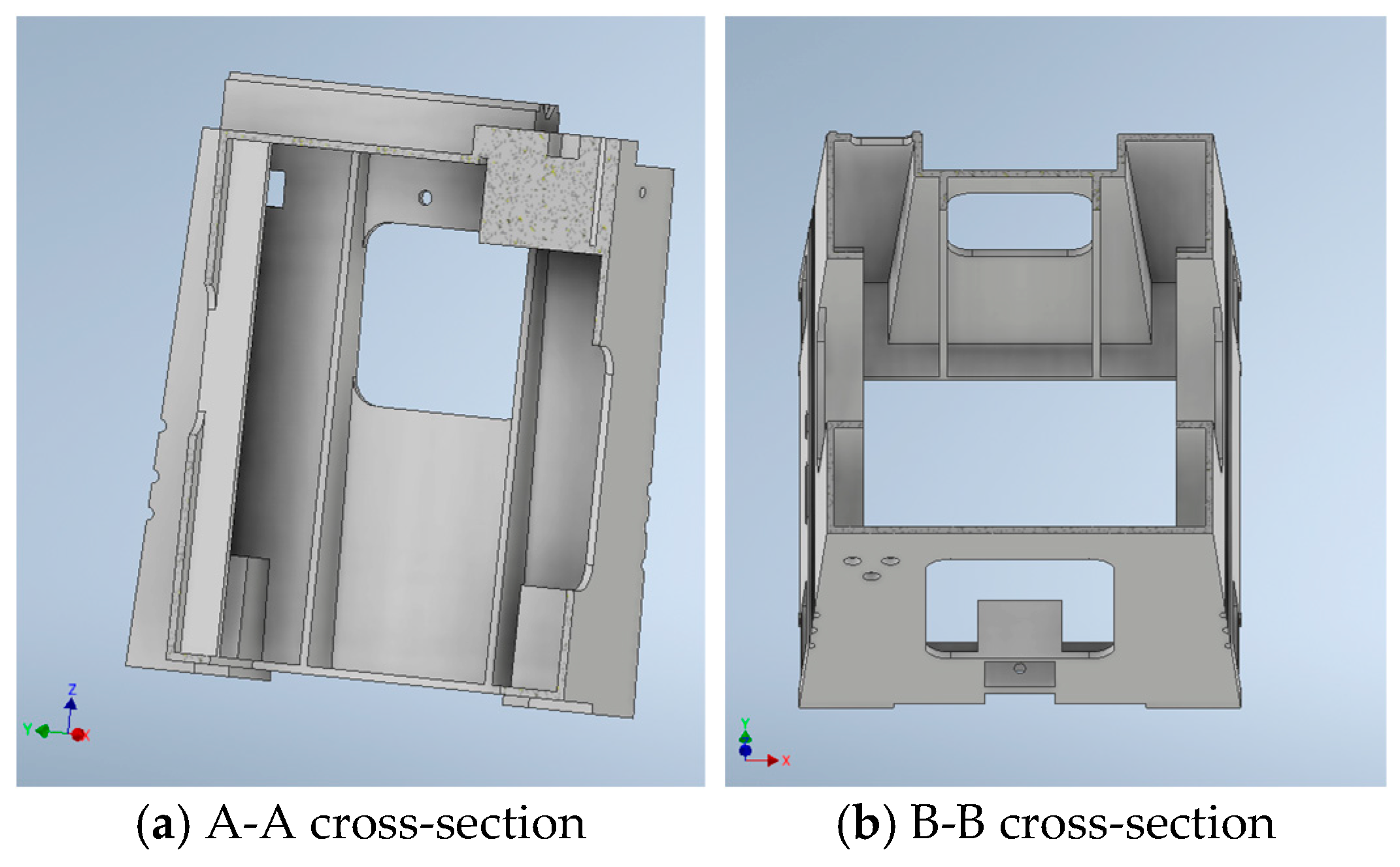
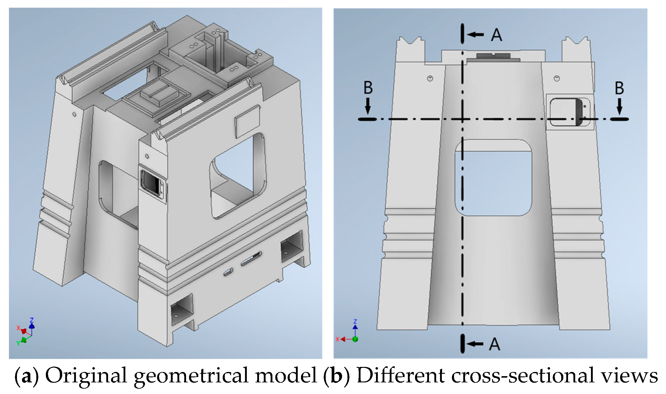
Similarly, in the static analysis, the maximum total deformation was found to occur at the central zone of the base top, as shown in Figure 3e. Moreover, the results of the modal analysis revealed that the first modal shape primarily exhibited torsional deformation, as shown later in the related modal shape diagram, while the second and third modal shapes showed bending deformations, as shown later in the related modal shape diagrams. To increase the natural frequencies, reduce deformation, and decrease weight, it is recommended to redesign the rib structure of the base to improve the structural performance and durability. Figure 9 shows the original geometric model and different cross-sectional views of the base subsystem. The geometrical models viewed along these different cross-sectional directions, i.e., A-A and B-B, for this subsystem are shown in Figure 10a and Figure 10b, respectively.
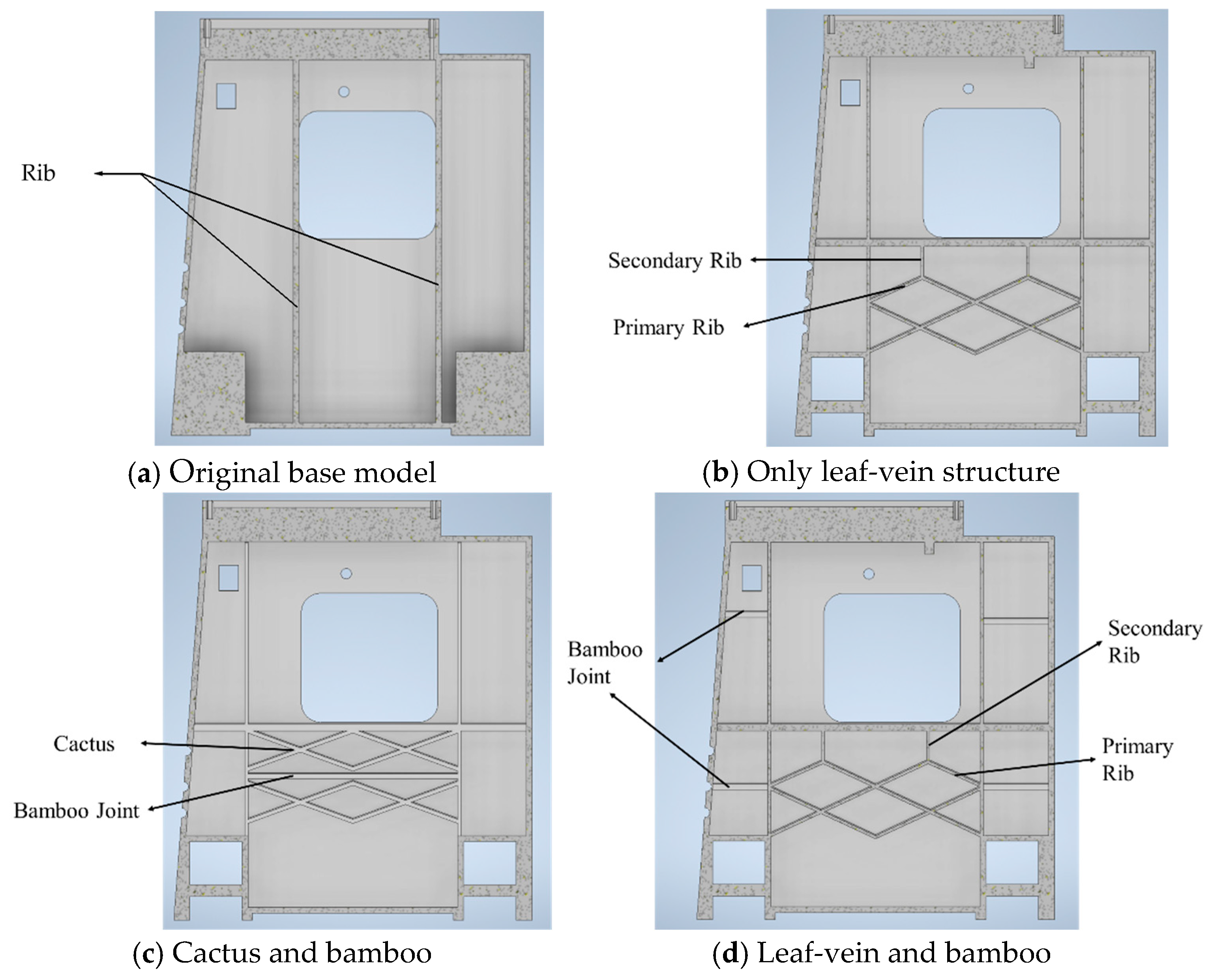
In the design, analysis, and modification processes, a modal analysis is first conducted on the original model to identify the weak stiffness points in the structure, and then some rib structures are removed from the original model to prepare for structural redesign and reinforcement. Based on the existing literature study, the ribs are redesigned and repositioned to address these weaker stiffness areas. The primary ribs are inspired by the main veins of the leaves and are placed in regions most prone to deformation to support the significant loadings. The secondary ribs are biomimetically arranged in a branching configuration around the primary ribs, forming a mesh-like structure that provides supplementary reinforcement, as shown in Figure 11b,d. Similarly, there are also three rib redesign models for the base. That is, a biomimetic rib based solely on the leaf vein structure, as shown in Figure 11b, a cactus is combined with a bamboo model, as shown in Figure 11c, and a leaf vein is combined with a bamboo model, as shown in Figure 11d. These designs are analyzed to assess their effectiveness in enhancing rigidity and reducing weight. Finally, the newly designed bionic models underwent further modal and static analyses and were compared with the original model to confirm the improvements in natural frequencies, deformation reduction, and lightweight performance. These steps not only enhance structural efficiency but also apply advanced design concepts to enhance the structural performance of the model.
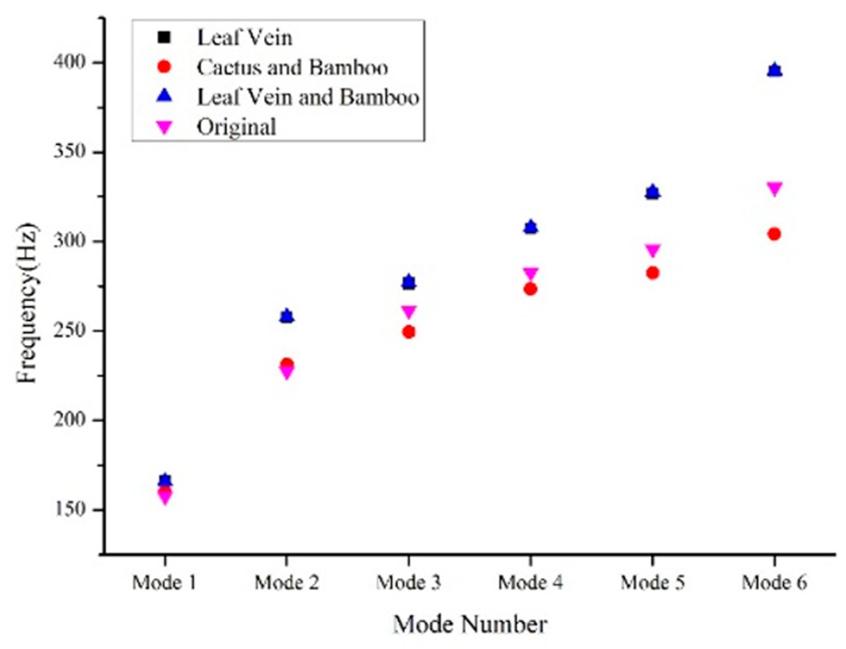
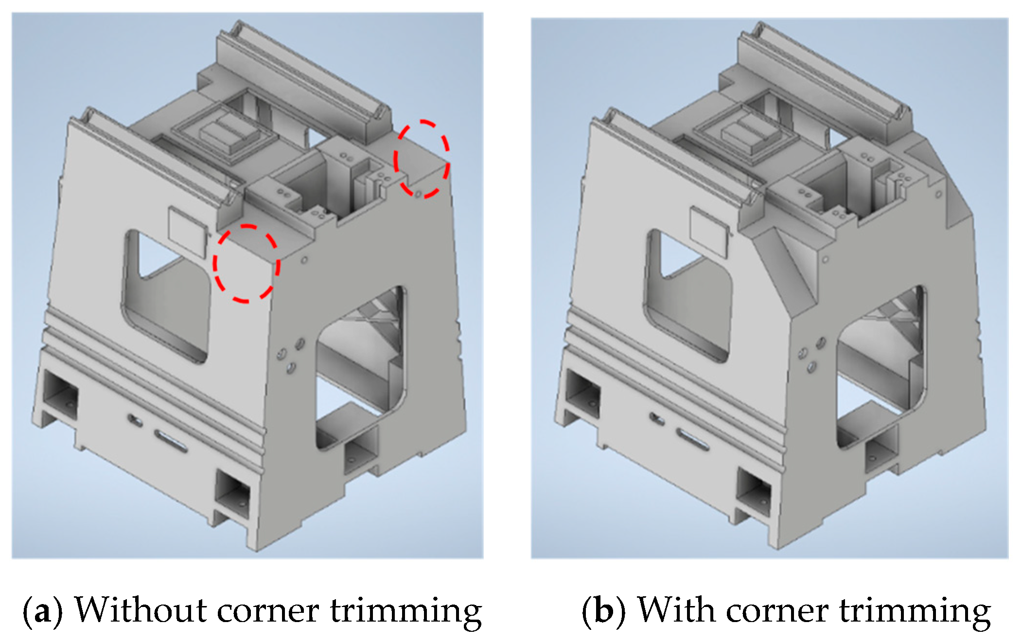
This study focuses on the structural biomimetic design of a grinding machine-tool base through multiple combinations of the structural features, such as leaf vein, cactus, and bamboo, to optimize the rib configuration and layout. As mentioned above, the leaf vein-inspired structure offers efficient loading support and stress disperse distribution, helping to reduce deformation and enhance load-bearing capacity. The cactus-inspired mesh structure provides excellent torsional rigidity, improving structural stability and toughness, while bamboo joint features enhance compressive strength and vibration-damping capacity, making them suitable for high-speed precision machining. The results obtained from the modal analysis for these redesigns are shown in Table 5 and Figure 12, which indicate the distinct biomimetic rib design models. The natural frequencies obtained for the leaf vein-bamboo combined rib structure are almost prevail to the other design plans, but the first mode frequency is less than the leaf vein structure, and the greater weight is accompanied. However, the natural frequencies are very close to each other, but the weight difference is obvious for these two newly designed plans. Hence, the leaf vein-inspired rib design is regarded as a temporarily better bionic model for the base subsystem from the overall assessment. Moreover, in order to reduce the weight of this subsystem, this temporarily better bionic model is further studied with corner trimming (redundant zones) with the aim of achieving an additional weight reduction while the high rigidity is still maintained. As a consequence, a final better bionic model for the base subsystem may be obtained in this study.
To further reduce the weight possibly of this temporarily better bionic base inspired by leaf veins, this study tries to remove some redundant regions within the subsystem model, subject to the constraint of high rigidity. Figure 13b shows this modification of corner trimming, which is negligible for loading support. The geometric solid models with and without corner trimming in this temporarily better bionic structure are shown in Figure 13, and the natural frequency and lightweightness are also employed as the performance assessment indicators subsequently. Table 6 further shows the comparisons of the natural frequency and weight with and without corner trimming of this temporarily better bionic base model. The results indicate that, by carefully modifying this temporarily better bionic model, the high rigidity can still be maintained while the weight reduction can be further achieved simultaneously, making the base more suitable for high-speed precision machining. The leaf vein bionic base reinforcement, achieved by adjusting rib layout and additional corner trimming, significantly improves structural stability while minimizing the material redundancy. As compared to the temporarily better bionic model without corner trimming, the modification base further reduces weight, demonstrating the advantage of biomimetic design in balancing lightness and stiffness. Unlike conventional rigidity reinforcement methods, biomimetic strategies draw from nature’s mechanical principles to optimize internal support structures, achieving both high rigidity and weight reduction simultaneously.
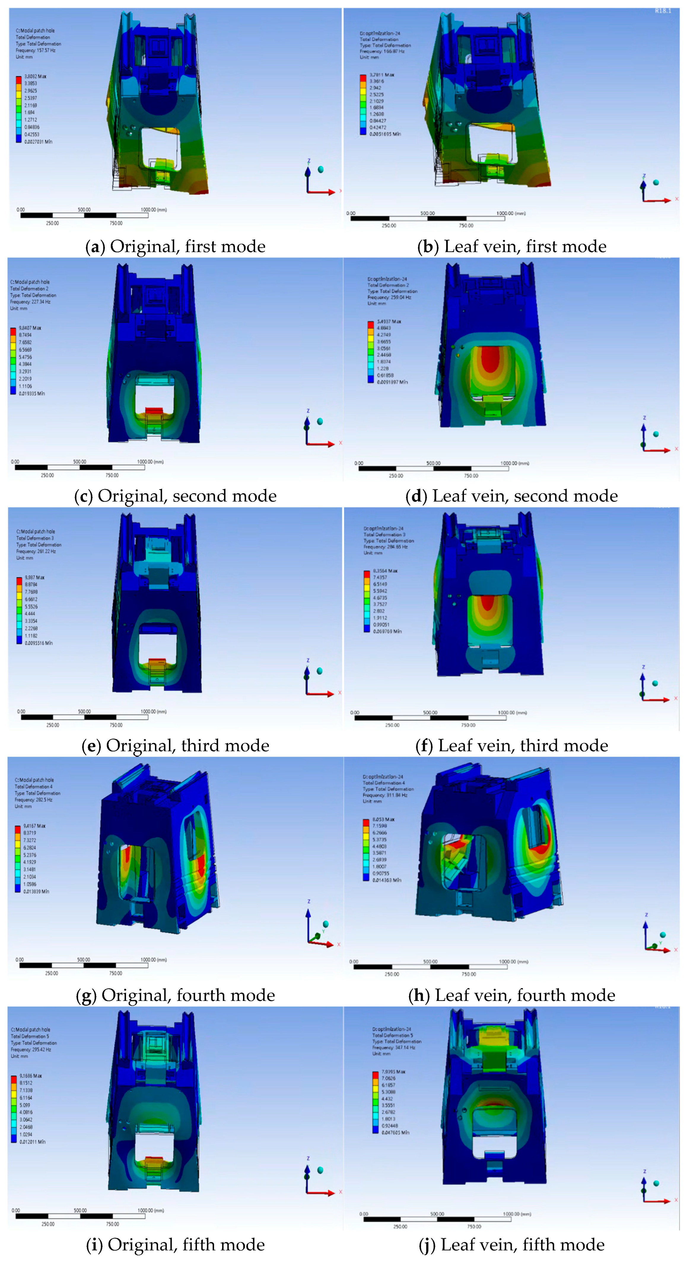
From the perspective of bending and torsional behavior, the biomimetic rib structure of the base, inspired solely by leaf structure, exhibits an excellent structural rigidity enhancement, as evidenced by the overall increase in natural frequencies. The level of the first natural frequency indicates improved torsional stiffness, suggesting that the structure is more capable of resisting deformation induced by torsional loads at the initial stage, as shown by the contrast between Figure 14a and Figure 14b. Furthermore, the increases in the second and third mode natural frequencies reflect enhanced resistance to bending deformation, which aligns with the inherent features of leaf vein structures in nature, where the multi-directional loads and structural support could be dispersed, distributed, and supported, respectively, by their induced mechanical functions. These improvements are shown by the contrast between Figure 14c,d and Figure 14e,f.

3.4. Column Subsystem

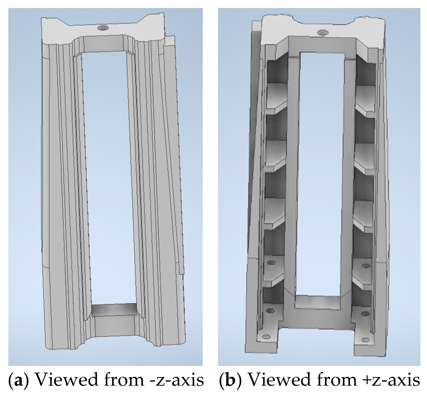
Figure 15 shows the original geometrical models of the column subsystem viewed from different axial directions. Similarly, in the static analysis, it was observed that the deformation of the column gradually increases from the bottom end to the top surface, with the maximum deformation occurring at the top surface, as shown in Figure 3b. The objectives of the redesign include increasing the natural frequency to make the structure more robust and less vibration, decreasing the maximum deformation by reinforcing the critical areas, and reducing the weight through biomimetic structural design.
To enhance the structural performance of the column subsystem while achieving both lightweight construction and high rigidity, it is beneficial to draw inspiration from structural prototypes found in nature, such as bones, bamboo, plant stems, and hornbill beaks. These biological structures have evolved over time to optimize material distribution in space, exhibiting two key design principles, i.e., load-adaptive orientation and functionally graded material distribution. Fibers within the femur exhibit highly anisotropic arrangements, effectively enhancing the structure’s resistance to deformation in specific directions is an example of one principle, while the other principle can be observed in the multi-layered architecture of hornbill beaks and hollow plant stems. By mimicking the geometric features and design strategies of these biological structures, the column design can incorporate bio-inspired configurations, particularly in the arrangement and layout of the internal ribs.
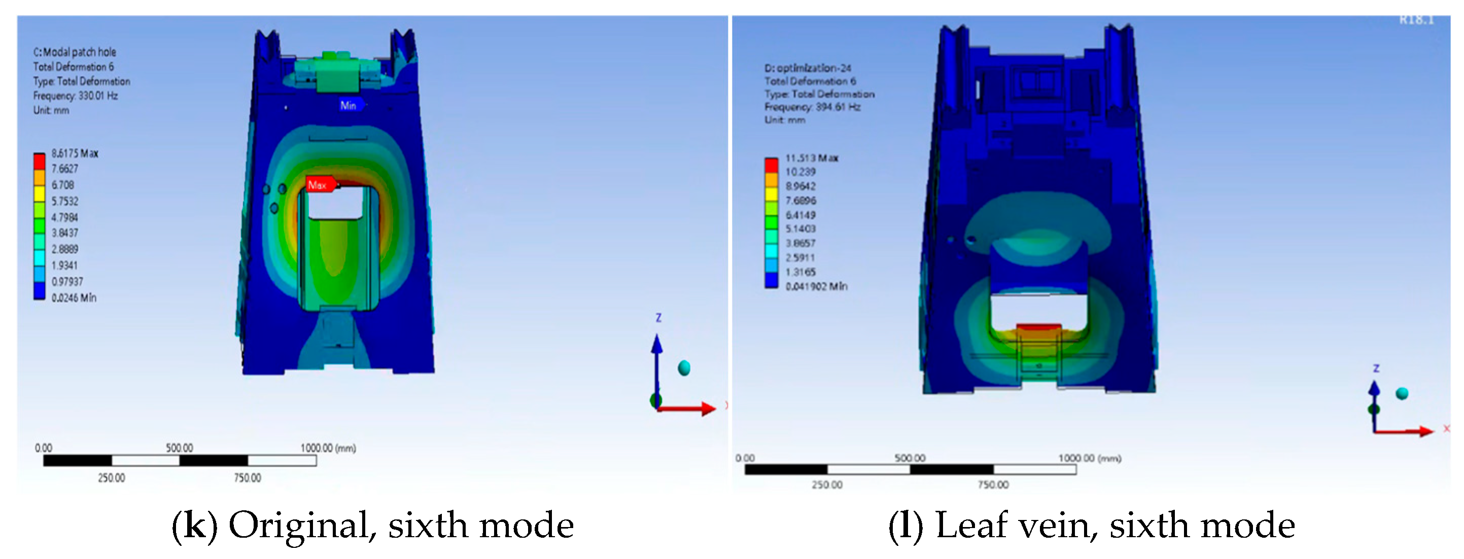
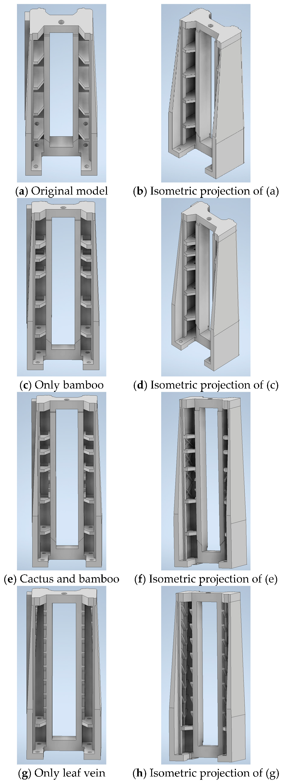
Firstly, through the static and modal analyses, the weaker stiffness areas or critical areas in the original column model were also analyzed and identified for improvement. Next, based on the existing literature study, these weak points were redesigned, particularly adjusting the middle zone of the rib structure in the column, which showed less deformation in the modal analysis and was chosen as the target area for weight reduction. To compensate for the potential loss of rigidity due to this material removal, several additional ribs were added using a biomimetic design similar to the structure of a bamboo joint to enhance the structural load-bearing efficiency and resistance, consequently improving torsional and bending performance. Similarly, there are also three rib redesign models for the column to analyze their potential effects in enhancing rigidity and lightweight construction. That is, a biomimetic rib based solely on the bamboo structure, as shown in Figure 16c,d, a cactus combined with a bamboo model, as shown in Figure 16e,f, and a biomimetic rib based solely on the leaf vein structure, as shown in Figure 16g,h. Finally, the modal and static analyses were conducted on the newly designed models and compared with the original one to assess the structural performance of these models in improving natural frequency, reducing deformation, and achieving weight reduction.
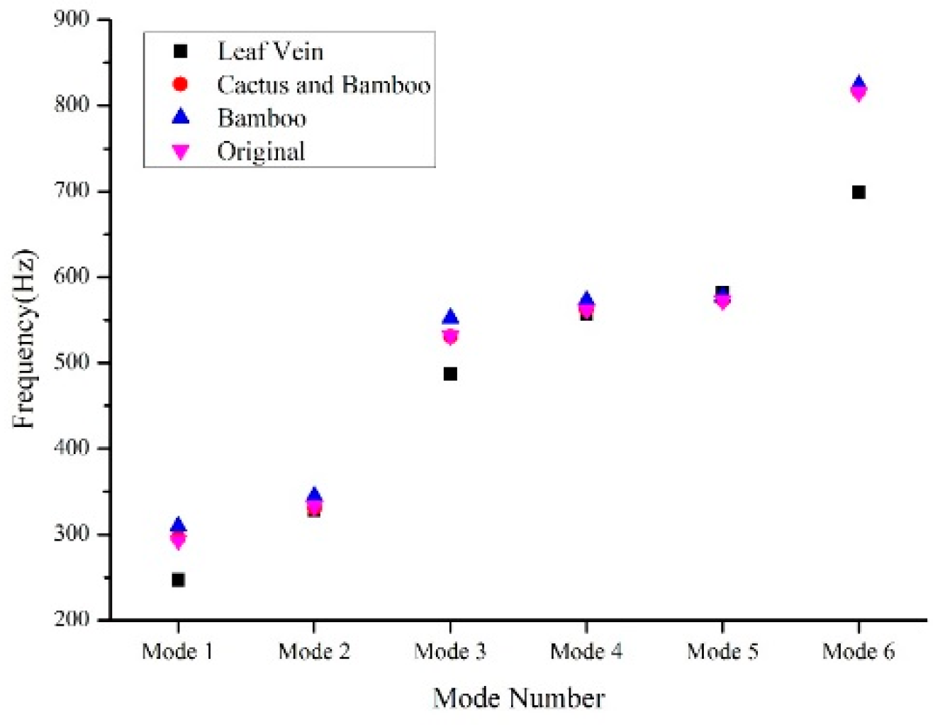
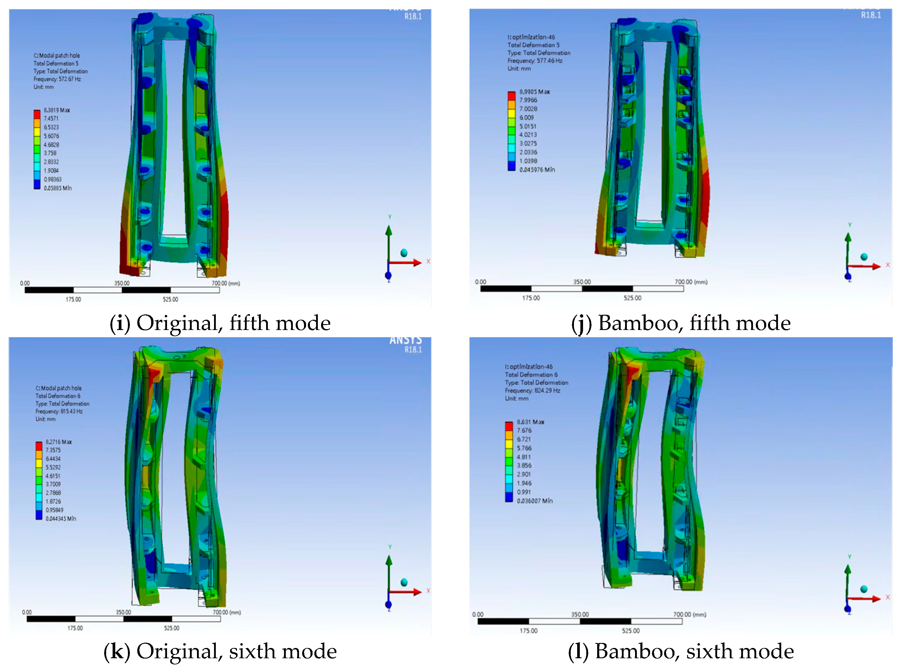
This study conducted a comparative analysis of biomimetic rib designs for the column subsystem, assessing the effects of three distinct biological inspirations, i.e., only bamboo joint, cactus combined with bamboo, and only leaf vein structures, on rigidity and lightweight performance enhancements. As mentioned above, the bamboo joint node provided the outstanding compressive and bending resistance, effectively reducing deformation and enhancing structural stability. The cactus-inspired diagonal cross and mesh-like structures, on the other hand, offered superior torsional rigidity, making it suitable for vibration-prone environments in high-speed precision machining. The results obtained from the modal analysis for these bionic models, as shown in Table 7 and Figure 17, illustrate that the natural frequencies and weight for the bamboo joint structure almost prevail over the other design plans. Hence, the better bionic model for the column subsystem is inspired by the bamboo joint node, which may balance the weight reduction and stiffness enhancement, leading to reinforced mechanical performance. As a result, it was selected as the preferred design for the column structure. In the first modal shape, the bamboo-inspired bionic column exhibits significantly improved torsional resistance compared to the original design, as shown by the contrast in Figure 18a,b. In the second and third modal shapes, a noticeable suppression of bending deformation can be observed, indicating that the bamboo-inspired column is more effective in disperse distributing and withstanding external loads under bending deformations. This contributes substantially to the enhancement of the overall structural stiffness, as shown by the contrast between Figure 18c,d and Figure 18e,f.
4. Results and Discussion

The larger deformation or weaker stiffness areas in the original designs of the worktable, base, and column were identified first, and the rigidity reinforcement models through biomimetic design were developed subsequently. The better bionic subsystems obtained were then substituted for the corresponding ones originally assembled in the grinding machine-tool model. To assess the overall effectiveness of the biomimetic design, a structural performance comparison between the original and the better bionic models of the entire machine-tool was conducted. The main aspects assessed include the natural frequency, modal shapes, weight, and maximum total deformation. The goal is to optimize the engineering design by mimicking the structure features found in nature, thereby improving the machine’s operational efficiency, structural robustness, and machining stability.
Four distinct biomimetic design models of the entire machine-tool are investigated in this study. That is, one of the better bionic subsystems, such as the worktable, base, and column, substituted the corresponding original one in the entire machine-tool model at each time, respectively. In addition, an original entire machine-tool model was replaced correspondingly by all the above better bionic structures at the same time. Therefore, an entire machine-tool model with only the better bionic worktable structure, a model with only the better bionic base structure, a model with only the better bionic column structure, and a model with all the above better bionic structures together were acquired. These redesigned entire machine-tool models were compared respectively with the original ones based on several performances just mentioned above, as shown in Table 8. Through these comparisons, this study may ascertain how each better bionic model ultimately affects the overall machine’s performance and determine the most proper design solutions.
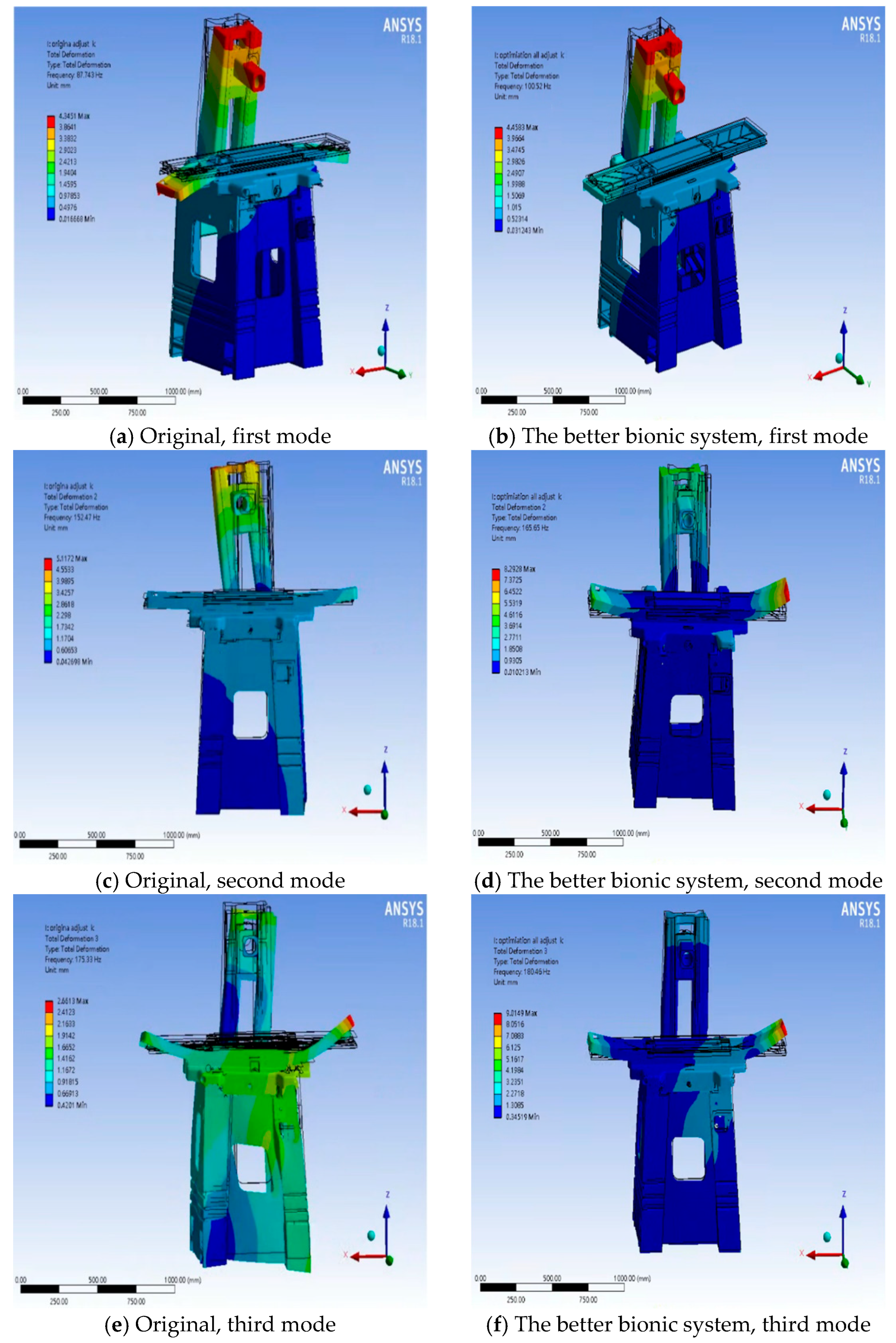
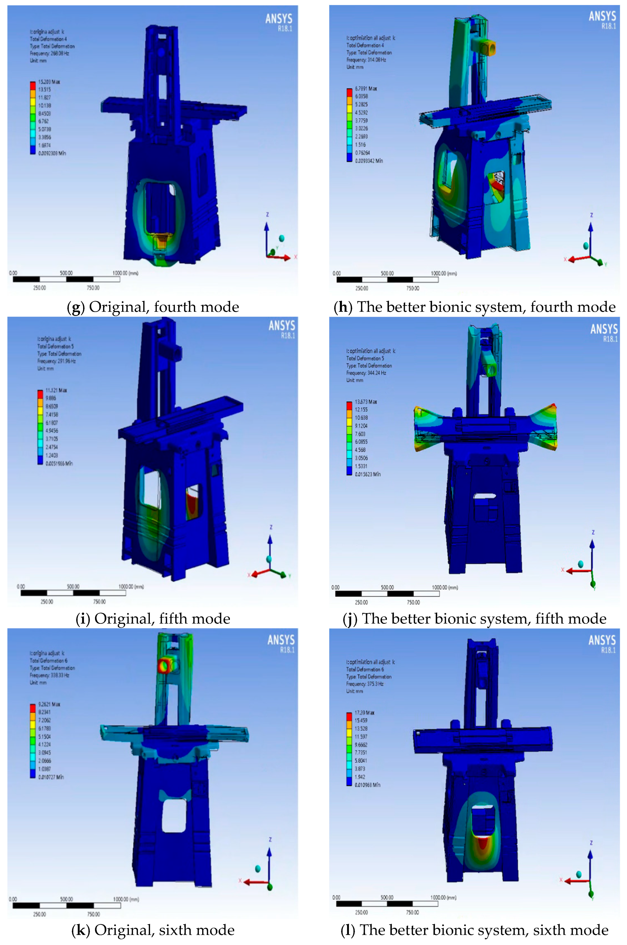
In terms of the natural frequencies, the entire machine-tool model incorporating the better bionic worktable, base, and column subsystems simultaneously demonstrates a 14.56% increase in the first mode natural frequency as compared to the original model, which is regarded as a better bionic entire machine-tool model. Specifically, the worktable had a more significant influence on the fourth and fifth mode natural frequencies; the base had a greater influence on the first and fourth mode natural frequencies; and the column mainly affected the third mode natural frequency. Detailed results of the better bionic entire machine-tool model show that the first, second, and third mode natural frequencies increased from 87.743 to 100.52 Hz, from 152.47 to 165.65 Hz, and from 175.33 to 180.46 Hz, respectively. These findings indicate that the biomimetic design not only effectively reduces the weight of the mechanical structure but also significantly enhances its dynamic performance, particularly in terms of natural frequency.
In the first modal shape of the better bionic entire machine-tool model, the bionic rib structure of the worktable demonstrates strong bending resistance, indicating higher stiffness and deformation resistance when subjected to bending moments primarily along the z-axis, as shown by the contrast between Figure 19a and Figure 19b. In the second modal shape, the bamboo inspired bionic columns exhibit a pronounced torsional resistance, as shown by the contrast between Figure 19c and Figure 19d. In the third modal shape, the bamboo-inspired columns show an effective suppression of the bending deformation, while the bionic rib structure of the base, modeled by leaf veins, also reveals enhanced resistance to bending deformation, as shown by the contrast between Figure 19e and Figure 19f.
In this study, biomimetic design was successfully applied to reduce the weight of the important subsystems, such as the worktable, base, and column, thereby achieving the desired lightweight construction. Moreover, in order to verify whether the structural rigidity of the entire machine-tool model was improved after the biomimetic designs, the static and modal analyses on this model were conducted once again. The results confirmed that, through the combination of biomimetic design and stiffness assessment, not only is the subsystem stiffness achieved, but the entire structural rigidity is also significantly enhanced. These outcomes support the main objective of this study, i.e., to realize lightweight constructions while simultaneously increasing the structural stiffness, demonstrating the effective integration of lightweight and high-rigidity structural design.
The specific stiffness is an indicator of stiffness relative to the product of weight and deformation, which is calculated by referring the formula in [5], i.e., specific stiffness = E/(W × d), where E and W are the Young’s modulus and weight of the subsystem, respectively, and d is the maximum deformation under the combined weight loadings of workpiece and machine-tool itself. From Table 9, Table 10 and Table 11, it can be observed that the weights of the better bionic worktable, base, and column were successfully reduced by the biomimetic designs. Additionally, the rigidity enhancements of the better redesigned (bionic) models were also confirmed by the results obtained from the modal and static analyses, which the effectiveness of the biomimetic structural design is positively verified consequently. Specifically, the weights of the better bionic worktable, base, and column subsystems are reduced from 63.182, 331.58, and 83.629 kg to 62.475, 324.8, and 83.515 kg, respectively. The specific stiffnesses of the above subsystems are increased by 67.55%, 35.58%, and 7.07%, respectively. In addition, the maximum total deformations of these better bionic subsystems were reduced by 39.64%, 24.7%, and 6.48%, respectively.
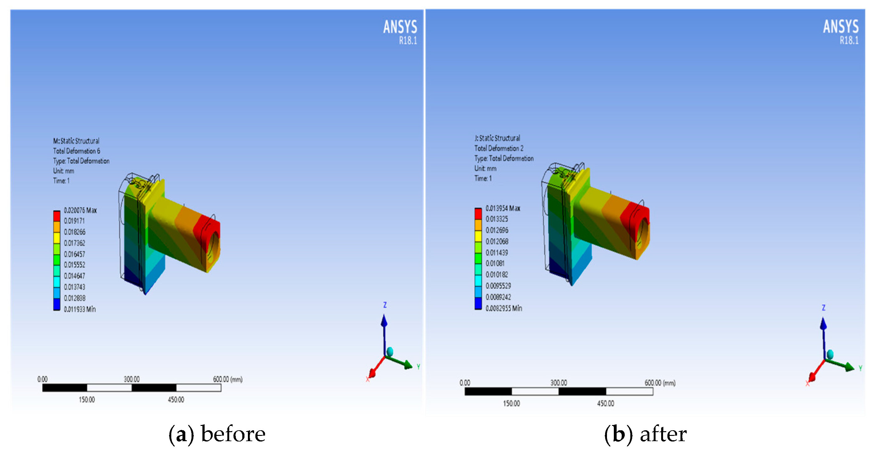
Furthermore, the comparisons of the maximum total deformation of the headstock and of the maximum deformation and weight of the entire machine-tool model before and after those better bionic subsystems were substituted in the original grinding machine-tool shown in Table 12 and Figure 20. The maximum total deformations of the headstock and better bionic entire machine-tool are decreased by 26.95% and 39.64%, respectively. At the same time, the total weight of the better entire bionic machine-tool is reduced by 1.25%, proving that the biomimetic design significantly enhances structural rigidity while achieving lightweight improvement. These results demonstrate that biomimetic design holds great potential and benefits in the development of machine tools.

5. Conclusions

In this study, structural performance enhancements were performed in the important subsystems of a grinding machine-tool using biomimetic design. Based on the results from the static and modal analyses, particularly the larger total deformations, structural redesigns were conducted for the worktable, base, and column subsystems by incorporating the natural growth features of leaf veins, cacti, and bamboos. The comparative analyses of promotions in natural frequency, modal shape, and lightweightness were conducted for these bionic subsystems. As a result, the better subsystems were obtained and substituted for the corresponding ones originally assembled in the grinding machine-tool for further investigations of stiffness, lightweightness, and total deformation. The conclusions drawn from the above analyses are summarized as follows:
  • One of the first three mode natural frequencies of a better bionic worktable (leaf vein and cactus), a better bionic base (leaf vein) with corner trimming, and a better bionic column (bamboo) are increased up to 7.07%, 14.04%, and 5.58%, respectively, accompanied by 1.12%, 2.04%, and 0.14% weight reductions, respectively. Additionally, the modal analysis results also exhibit the enhancements in bending and torsional resistances in these better bionic subsystems. In a word, the biomimetic designs not only increased structural rigidity but also contributed to weight reduction, improving the overall machine-tool performance.
  • The specific stiffnesses of the worktable, base, and column are increased by 67.55%, 35.58%, and 7.07%, respectively, accompanied by the maximum total deformations being decreased by 39.64%, 24.7%, and 6.48%, respectively. These outcomes demonstrate the effectiveness of the biomimetic design.
  • After the original grinding machine-tool is substituted with those better bionic subsystems, one of the first three mode natural frequencies is increased up to 14.56%, weight is reduced by 1.25%, and maximum total deformation is decreased by 39.64%. At the same time, the maximum total deformation for the headstock is reduced by 26.95%.

Author Contributions

Conceptualization, supervision, and writing, S.-Y.L.; methodology and analysis, Y.-T.L. All authors have read and agreed to the published version of the manuscript.

Funding

This research received no external funding.

Institutional Review Board Statement

Ethical review and approval were waived for this study since it did not involve research with living organisms.

Informed Consent Statement

Not applicable.

Data Availability Statement

Correspondence and requests for materials should be addressed to Shen-Yung Lin. The data are not publicly available due to a patent in review.

Acknowledgments

The authors acknowledge the Smart Machine and Intelligent Manufacturing Research Center of National Formosa University for their support in this research.

Conflicts of Interest

The authors declare no conflicts of interest.

References

  1. Li, B.; Hong, J.; Liu, Z. Stiffness design of machine tool structures by a biologically inspired topology optimization method. Int. J. Mach. Tool Manuf. 2014, 84, 33–44. [Google Scholar] [CrossRef]
  2. Gao, X.; Li, B.; Hong, J.; Guo, J. Stiffness modeling of machine tools based on machining space analysis. Int. J. Adv. Manuf. Technol. 2016, 86, 2093–2106. [Google Scholar] [CrossRef]
  3. Revanasiddesh, B.V.; Taj, A.P.; Kumar, N.S.N.; Suresh, B.S. Extraction of modal parameters of CNC lathe bed using finite element and experimental method. Mater. Today. Proc. 2020, 24, 398–405. [Google Scholar] [CrossRef]
  4. Gao, D.Q.; Zhang, F.; Mao, Z.Y.; Lin, H.; Yi, J.M. Finite Element Analysis and Structure Optimization of Machine Tool Worktable. Appl. Mech. Mater. 2011, 80–81, 985–989. [Google Scholar] [CrossRef]
  5. Zhao, L.; Chen, W.-Y.; Ma, J.-F.; Yang, Y.-B. Structural Bionic Design and Experimental Verification of a Machine Tool Column. J. Bionic Eng. 2008, 5, 46–52. [Google Scholar] [CrossRef]
  6. Xing, D.; Chen, W.; Zhao, L.; Ma, J. Structural bionic design for high-speed machine tool working table based on distribution rules of leaf veins. Sci. China Technol. Sci. 2012, 55, 2091–2098. [Google Scholar] [CrossRef]
  7. Zhao, L.; Ma, J.; Chen, W.; Guo, H. Lightweight design and verification of gantry machining center crossbeam based on structural bionics. J. Bionic Eng. 2011, 8, 201–206. [Google Scholar] [CrossRef]
  8. Gao, H.; Sun, J.; Chen, W.; Zhang, Y.; Wu, Q. Structural bionic design for a machine tool column based on leaf veins. Proc. Inst. Mech. Eng. Pt. C J. Mechan. Eng. Sci. 2018, 232, 2764–2773. [Google Scholar] [CrossRef]
  9. Liu, S.; Ye, W.; Lou, P.; Chen, W.; Huang, J.; Xiao, L. Bionic design for column of gantry machining center to improve the static and dynamic performance. Shock Vib. 2012, 19, 493–504. [Google Scholar] [CrossRef]
  10. Li, Y.X.; Wu, F.H.; Wu, P. Bionic column design inspired by macro and micro characteristics of bamboo. J. Biomim. Biomater. Bi. 2016, 29, 1–8. [Google Scholar] [CrossRef]
  11. Gao, D.Q.; Zhang, F.; Mao, Z.Y.; Lin, H.; Yi, J.M. Application of honeycomb structure in machine tool table. Adv. Mater. Res. 2011, 308, 1233–1237. [Google Scholar] [CrossRef]
  12. Jiao, H.; Zhang, Y.; Chen, W. The lightweight design of low RCS pylon based on structural bionics. J. Bionic Eng. 2010, 7, 182–190. [Google Scholar] [CrossRef]
  13. Zhang, T.; Wang, A.; Wang, Q.; Guan, F. Bending characteristics analysis and lightweight design of a bionic beam inspired by bamboo structures. Thin Wall Struct. 2019, 142, 476–498. [Google Scholar] [CrossRef]
  14. Xing, D.; Chen, W.; Xing, D.; Li, Z. Lightweight design for an aircraft reinforcing frame based on structural bionics. Proc. Inst. Mech. Eng. Pt. G J. Aerosp. Eng. 2013, 227, 1338–1346. [Google Scholar] [CrossRef]
  15. Yan, S.; Li, B.; Hong, J. Bionic design and verification of high-precision machine tool structures. Int. J. Adv. Manuf. Technol. 2015, 81, 73–85. [Google Scholar] [CrossRef]
  16. Liu, S.; Yang, C.; Chen, G.; Lin, M.; Qin, J.; Li, M. Multi-objective optimization design for the table of a CNC machine tool based on bionic structures. T. Can. Soc. Mech. Eng. 2024, 48, 369–392. [Google Scholar] [CrossRef]
  17. Wu, J.; Zhang, Y.; Zhang, F.; Hou, Y.; Yan, X. A bionic tree-liked fractal structure as energy absorber under axial loading. Eng. Struct. 2021, 245, 112914. [Google Scholar] [CrossRef]
  18. Zhang, H.; Ding, X.; Dong, X.; Xiong, M. Optimal topology design of internal stiffeners for machine pedestal structures using biological branching phenomena. Struct. Multidiscip. Optim. 2018, 57, 2323–2338. [Google Scholar] [CrossRef]
  19. Cai, K.; Shi, J. A bionic approach for topology optimization for tension-only or compression-only design. J. Bionic Eng. 2010, 7, 397–404. [Google Scholar] [CrossRef]
  20. Ji, J.; Ding, X.; Xiong, M. Optimal stiffener layout of plate/shell structures by bionic growth method. Comput. Struct. 2014, 135, 88–99. [Google Scholar] [CrossRef]
  21. Zhao, L.; Ma, J.; Wang, T.; Xing, D. Lightweight Design of Mechanical Structures based on Structural Bionic Methodology. J. Bionic Eng. 2010, 7, S224–S231. [Google Scholar] [CrossRef]
  22. Li, B.; Yan, S.; Lin, Q. Automated Layout Design of Stiffened Container Structures Based on the Morphology of Plant Ramifications. J. Bionic Eng. 2016, 13, 344–354. [Google Scholar] [CrossRef]
Figure 1. The dimensions of a 3D solid geometrical model, gridded pattern, and boundary conditions for FEA of a grinding machine-tool.
Applsci 15 09449 g001
Figure 2. The relationship among Mesh-Average, 1st mode natural frequency, and number of nodes for the base, column, and worktable subsystems, respectively. Top to bottom: base, column, and worktable, respectively.
Applsci 15 09449 g002
Figure 3. The total deformation distributions of a grinding machine-tool and its subsystems.
Applsci 15 09449 g003
Figure 4. Pictures of selected natural structures. Left to right: leaf vein, Mexican cactus, and bamboo sourced from Youtube, Reddit, and conbam.info, respectively.
Applsci 15 09449 g004
Figure 5. Flowchart for biomimetic design of a grinding machine-tool in this study.
Applsci 15 09449 g005
Figure 6. Different rib design models for worktable subsystem.
Applsci 15 09449 g006
Figure 7. Comparisons of the first six mode natural frequencies among distinct biomimetic design models for worktable subsystem.
Applsci 15 09449 g007
Figure 8. Comparisons of the modal shapes corresponding to the first six modes between the original model and the better bionic base (combination of leaf vein and cactus) model.
Applsci 15 09449 g008aApplsci 15 09449 g008b
Figure 9. Geometrical model and cross-sectional view of the base subsystem.
Applsci 15 09449 g009
Figure 10. Geometrical models viewed along different cross-sectional directions for base subsystem.
Applsci 15 09449 g010
Figure 11. Different bionic rib design models for A-A cross-sectional view of the base subsystem.
Applsci 15 09449 g011
Figure 12. Comparisons of the first six mode natural frequencies among distinct biomimetic design models for the base subsystem.
Applsci 15 09449 g012
Figure 13. The temporarily better bionic base (leaf vein) subsystem model with and without corner trimming.
Applsci 15 09449 g013
Figure 14. Comparisons of the modal shapes corresponding to the first six modes between the original model and a temporarily better bionic base (leaf vein) model with corner trimming.
Applsci 15 09449 g014aApplsci 15 09449 g014b
Figure 15. Original geometrical models of the column subsystem viewed from different axial directions.
Applsci 15 09449 g015
Figure 16. Distinct rib design models and their isometric projections for column subsystem viewed from +z-axis direction.
Applsci 15 09449 g016
Figure 17. Comparisons of the first six mode natural frequencies among distinct biomimetic design models for the column subsystem.
Applsci 15 09449 g017
Figure 18. Comparisons of the modal shapes corresponding to the first six modes between the original model and the better bionic base (bamboo) model.
Applsci 15 09449 g018aApplsci 15 09449 g018b
Figure 19. Comparisons of the modal shapes between the original model and the model assembled with the better bionic subsystems of the worktable, base, and column.
Applsci 15 09449 g019aApplsci 15 09449 g019b
Figure 20. Comparison of the maximum total deformation of the headstock before and after the better bionic subsystems were substituted in the original grinding machine-tool.
Applsci 15 09449 g020
Table 1. The material properties for the key subsystems of a grinding machine-tool.
PropertyElastic Modulus, MPaPoisson’s RatioDensity, kg/m3
Headstock 154,700 0.28 7362.5
Column 149,710 0.28 7362.5
Worktable 133,880 0.28 7308.8
Saddle 140,200 0.28 7402.07
Base 149,710 0.28 7362.5
Table 2. FEM mesh size and the number of elements and nodes in static and modal analyses.
GridMesh size, mmElementNode
Headstock1215,07524,975
Column12.5 60,529 100,589
Worktable10 85,511 146,747
Saddle12 87,566 141,238
Base10448,870738,931
Table 3. The maximum total deformation of the subsystems and the entire machine-tool.
SystemEntireColumnWorktableSaddleBase
Maximum deformation (mm)0.0453760.0192040.0453760.00300140.0075125
Table 4. Comparisons of the natural frequency and weight among distinct biomimetic geometrical models designed for worktable subsystem.
Worktable ModelVein-like RibCactus-like RibVein-Cactus Combined RibOriginal Model
Natural frequency
(Hz)
Mode 197.07993.10797.88393.14
Mode 2174.06169.74180.09168.66
Mode 3182.31175.61185.32173.09
Mode 4243.84237.22249.8225.33
Mode 5464.98443.43467.97445.21
Mode 6492.6488.38521.34494.7
Weight (kg)62.16662.90362.47563.182
Table 5. Comparisons of the natural frequency and weight among distinct biomimetic geometrical models designed for the base subsystem.
Base ModelVein-like RibCactus and Bamboo Combined RibLeaf Vein and Bamboo Combined RibOriginal Model
Natural frequency
(Hz)
Mode 1166.38160.17165.96157.67
Mode 2257.51231.32257.89227.47
Mode 3276.63249.39277.23261.42
Mode 4307.26273.57307.81282.68
Mode 5326.74282.43327.56295.65
Mode 6395.28304.16395.46330.33
Weight (kg)325.9326.01327.6331.58
Table 6. Comparisons of the natural frequency and weight of a temporarily better bionic base (leaf vein) model with and without corner trimming.
Bionic Base SubsystemWith Corner TrimmingWithout Corner TrimmingOriginal
Natural frequency
(Hz)
Mode 1167.12166.38157.67
Mode 2259.4257.51227.47
Mode 3285.09276.63261.42
Mode 4312.38307.26282.68
Mode 5347.74326.74295.65
Mode 6395.42395.28330.33
Weight (kg)324.8325.9331.58
Table 7. Comparisons of the natural frequency and weight among distinct biomimetic geometrical design models for the column subsystem.
Column ModelVein-like RibCactus and Bamboo Combined RibBamboo-like RibOriginal Model
Natural frequency
(Hz)
Mode 1246.81295.9309.52293.17
Mode 2327.9330.91344.92333.31
Mode 3487.2530.92552.38531.57
Mode 4556.4562.5572.92562.28
Mode 5581.36573.66577.46572.67
Mode 6698.67816.8824.29815.43
Weight (kg)83.58783.77683.51583.629
Table 8. Comparison of the natural frequencies corresponding to different modes of the entire machine-tool between the original model and the model assembled with distinct better bionic subsystems.
Modal
Mode
Original Entire Machine Models Assembled with Distinct Better Bionic Subsystems
WorktableBaseColumnWorktable, Base and Column
Freq. (Hz)Freq. (Hz)Freq. (Hz)Freq. (Hz)Freq. (Hz)
187.74390.116100.790.177100.52
2152.47163.89162.75158.75165.65
3175.33181.95176.69177.89180.46
4268.08296.3300.73294.54314.08
5291.96342.27314.65305.04344.24
6338.33351.84375.36347.69375.3
Table 9. Comparison of the weight, maximum total deformation, and specific stiffness between the original and the better bionic worktable subsystem.
ModelOriginalBionic Worktable
(leaf Vein and Cactus)
Deviation (%)
Weight (kg)63.18262.475−1.12
Maximum total deformation (mm)0.0453760.027388−39.64
Specific stiffness ( G P a k g 1 m m 1 )46.6977682378.2436532467.55
Table 10. Comparison of the weight, maximum total deformation, and specific stiffness between the original and the better bionic base subsystem.
ModelOriginal Bionic Base
(Leaf Vein)
Deviation (%)
Weight (kg)331.58324.8−2.04
Maximum total deformation (mm)0.00751250.0056568−24.70
Specific stiffness ( G P a k g 1 m m 1 )60.1004879781.4824287535.58
Table 11. Comparison of the weight, maximum total deformation, and specific stiffness between the original and the better bionic column subsystem.
ModelOriginalBionic Column (Bamboo)Deviation (%)
Weight (kg)83.62983.515−0.14
Maximum total deformation (mm)0.0192040.01796−6.48
Specific stiffness ( G P a k g 1 m m 1 )93.2185212699.811364457.07
Table 12. Comparisons of the maximum total deformation and weight of a better bionic entire machine-tool model, and of the maximum total deformation of the headstock before and after the better bionic subsystems were substituted in the original grinding machine-tool.
ModelOriginal
(Before)
Bionic
(After)
Deviation (%)
Maximum total deformation (mm)0.0453760.027388−39.64
Weight (kg)608.24600.65−1.25
Maximum deformation of Headstock (mm)0.0190690.01393−26.95
Disclaimer/Publisher’s Note: The statements, opinions and data contained in all publications are solely those of the individual author(s) and contributor(s) and not of MDPI and/or the editor(s). MDPI and/or the editor(s) disclaim responsibility for any injury to people or property resulting from any ideas, methods, instructions or products referred to in the content.