Article

Kinetics and Morphological Characteristics of CO2 Hydrate Formation Within Sandstone Fractures

1
State Key Laboratory of Intelligent Construction and Healthy Operation & Maintenance of Deep Underground Engineering, School of Mechanics and Civil Engineering, China University of Mining and Technology, Xuzhou 221116, China
2
Xinwen Mining Group Co., Ltd., Tai’an 271233, China
3
Key Laboratory of Coalbed Methane Resources and Reservoir Formation Process of the Ministry of Education, School of Resources and Geosciences, China University of Mining and Technology, Xuzhou 221116, China
4
YunLong Lake Laboratory of Deep Underground Science and Engineering, Xuzhou 221116, China
*
Author to whom correspondence should be addressed.
Appl. Sci. 2025, 15(17), 9440; https://doi.org/10.3390/app15179440
Submission received: 25 July 2025 / Revised: 19 August 2025 / Accepted: 24 August 2025 / Published: 28 August 2025

Abstract

Hydrate-based CO2 sequestration is considered one of the most promising methods in the field of carbon capture, utilization, and storage. The abundant fractured environments in marine sediments provide an ideal setting for the sequestration of CO2 hydrate. Investigating the kinetics and morphological characteristics of CO2 hydrate formation within fractures is a critical prerequisite for achieving efficient and safe CO2 sequestration using hydrate technology in subsea environments. Based on the aforementioned considerations, the kinetic experiments on the formation, dissociation, and reformation of CO2 hydrates were conducted using a high-pressure visualization experimental system in this study. The kinetic behaviors and morphological characteristics of CO2 hydrates within sandstone fractures were comprehensively investigated. Particular emphasis was placed on analyzing the effects of fracture width, type, and surface roughness on the processes of hydrate formation, dissociation, and reformation. The experimental results indicate the following: (1) At a formation pressure of 2.9 MPa, the 10 mm width fracture exhibited the shortest induction time, the longest formation duration, and the highest hydrate yield (approximately 0.52 mol) compared to the other two fracture widths. The formed CO2 hydrates exhibited a smooth, thin-walled morphology. (2) In X-type fractures, the formation of CO2 hydrates was characterized by concurrent induction and dissolution processes. Compared to I-type fractures, the hydrate formation process in X-type fractures exhibited shorter formation durations and generally lower hydrate yields. (3) An increase in fracture roughness enhances the number of nucleation sites for the formation of hydrates. In both fracture types (I-type and X-type), the induction time for CO2 hydrate formation was nearly negligible. However, a significant difference in the trend of formation duration was observed under varying roughness conditions. (4) Hydrate dissociation follows a diffusion-controlled mechanism, progressing from the fracture walls towards the interior. The maximum gas production was achieved in the 10 mm-width fracture, reaching 0.24 mol, indicating optimal heat and mass transfer conditions under this configuration. (5) During the reformation process, the induction time was significantly shortened due to the “memory effect.” However, the hydrate yield after the reformation process remained consistently lower than that of the first formation, which is primarily attributed to the high solubility of CO2 in the aqueous phase.

1. Introduction

Global warming has emerged as one of the most severe environmental challenges of the 21 st century, manifesting in phenomena such as glacier melting, sea-level rise, and ecosystem disruption [1]. The substantial emissions of greenhouse gases, particularly CO2, resulting from the combustion of fossil fuels, are the primary contributors to global warming [2,3,4]. Over the past decade, CO2 emissions have continued to rise, with global CO2 emissions from human activities projected to reach 41.6 billion tons in 2024 [5,6]. This upward trend underscores the urgent need for effective mitigation strategies. Carbon capture, utilization, and storage (CCUS) [7,8,9] is regarded as one of the most promising and effective technologies for reducing carbon emissions [10,11,12]. Among these, the hydrate-based CO2 sequestration (HBCS) method has demonstrated significant potential for development and has attracted widespread attention from scientists worldwide due to its distinct sequestration advantages [13].
When CO2 is injected into subsea sediments, particularly during the injection of dense CO2 into reservoirs exhibiting significant under pressure, a substantial Joule–Thomson effect may occur. The low temperatures generated around the wellbore may cause the pore water to freeze or form hydrates. The formation of hydrates alters the pore structure of the sediments, directly influencing their physical and mechanical properties. Experimental studies have shown that, as hydrates form, the hydrate crystals filling the sediment pores generally result in a decrease in permeability [14]. However, an increase in permeability has also been observed in certain clayey silt sediments [15]. Furthermore, the formation of CO2 hydrates obstructs the conductive pathways in the sediments, significantly increasing their resistivity [16]. Therefore, conducting systematic laboratory research to explore the formation mechanisms of CO2 hydrates induced by the Joule–Thomson effect is essential. This research will provide critical theoretical and technical support for understanding hydrate-based seabed CO2 storage, optimizing storage strategies, and enhancing storage efficiency.
CO2 hydrate is a metastable substance [17], composed of water molecules and guest gas molecules (e.g., CO2), and exhibits a distinct cage-like structure [18,19,20]. This structure not only possesses suitable formation conditions (close to the temperature and pressure conditions of the seafloor) and a high latent heat of phase transition, but also effectively captures and densely stores CO2, enabling its sequestration in vast submarine reservoirs [21]. Hydrates also exhibit a self-preservation effect [22], which can effectively prevent the large-scale dissociation of CO2 hydrates and subsequent leakage. CO2 hydrates also possess advantageous mechanical properties [23]. The cementation and filling effects of CO2 hydrates can enhance the strength and stiffness of the host sediments, thereby ensuring the long-term mechanical stability of submarine CO2 sequestration reservoirs. Therefore, the large-scale application of hydrate technology for CO2 sequestration in submarine environments could provide significant support for CCUS. To accelerate the hydrate formation rate and improve the CO2 sequestration efficiency in marine settings, it is essential to investigate the formation kinetics and morphological characteristics of CO2 hydrates.
The formation of CO2 hydrates is influenced by factors including temperature, pressure, and the presence of chemical or biological promoters. CO2 hydrates typically form under low-temperature and high-pressure conditions, and both decreasing temperature and increasing pressure could promote hydrate formation [24,25]. Misyura et al. [26] found that the dissociation rate of natural gas hydrates is considerably higher under low-temperature conditions. Teng et al. [27] demonstrated that increasing pressure is more effective than lowering temperature in enhancing the formation of CO2 hydrates. Research has demonstrated that promoters such as SDS, leucine, tryptophan, and methionine effectively reduce induction time and enhance hydrate formation kinetics [28,29,30,31]. The above studies indicate that the formation of CO2 hydrates is influenced by factors such as temperature, pressure, and chemical/biological promoters. Lowering the temperature, increasing the pressure, and adding chemical agents could effectively shorten the nucleation induction time and improve the hydrate formation rate.
The grain size, pore structure, and pore size of host sediments also significantly impact the formation kinetics and morphological characteristics of CO2 hydrates. Chen et al. [32] found that, as grain size and pore space decreased, the optimal initial water saturation for achieving maximum CO2 hydrate storage density increased. Rehman et al. [33] emphasized that an appropriate pore space range is crucial for rapid hydrate formation in silica sands with varying particle sizes. Mekala et al. [34] demonstrated that gas consumption increased with smaller silica sand particle sizes when using both pure water and seawater. Zhang et al. [35] confirmed that smaller quartz sand particles enhanced both the hydrate formation rate and the sequestration density. Zhao et al. [36] investigated CO2 hydrate dissociation in porous media using nuclear magnetic resonance (NMR) and found that dissociation rates induced by depressurization were limited by pore size and pressure increase. Similarly, Chen et al. [37] observed that, for a given hydrate volume, dissociation rates were lower in larger pores, highlighting the significant influence of pore size. Wu et al. [38] also found that CO2 hydrates in quartz sand primarily exist as pore-filling forms, with the dissociation duration closely related to hydrate saturation—higher saturation resulting in prolonged dissociation. Although the aforementioned studies offer deeper insights into the influence of sediment grain size, pore structure, and pore size on the formation and dissociation of CO2 hydrates, the impact of fracture space on hydrate formation dynamics and morphological characteristics remains insufficiently explored.
Numerous fracture spaces have been identified in marine formations [39] and are regarded as optimal sites for CO2 sequestration through hydrate methods. In comparison to pores in reservoirs, fractures have larger widths, thereby providing more space for hydrate formation and mitigating the impact of capillary effects. The heterogeneity of fractures, including variations in roughness and type, affects the distribution and migration of gas and water, thereby influencing the nucleation and growth morphology of hydrates, as illustrated in Figure 1. Therefore, studying the formation kinetics and morphological characteristics of CO2 hydrates within fractures is a crucial prerequisite for achieving effective marine CO2 sequestration through hydrate-based methods. However, current research on hydrate formation behavior within fractures remains limited and lacks a systematic understanding, making it difficult to provide sufficient guidance for engineering applications. Therefore, a self-developed high-pressure, low-temperature hydrate reaction system was utilized in this study to conduct observational experiments on the formation, dissociation, and reformation of CO2 hydrates within fractures. The research focused on the investigation of formation kinetics and the morphological characteristics of CO2 hydrates under varying fracture widths, types, and surface roughness conditions. The effects of these factors on the induction time, formation duration, hydrate yield, and morphological characteristics of CO2 hydrates were systematically analyzed.

2. Methodology

2.1. Experimental Apparatuses and Materials

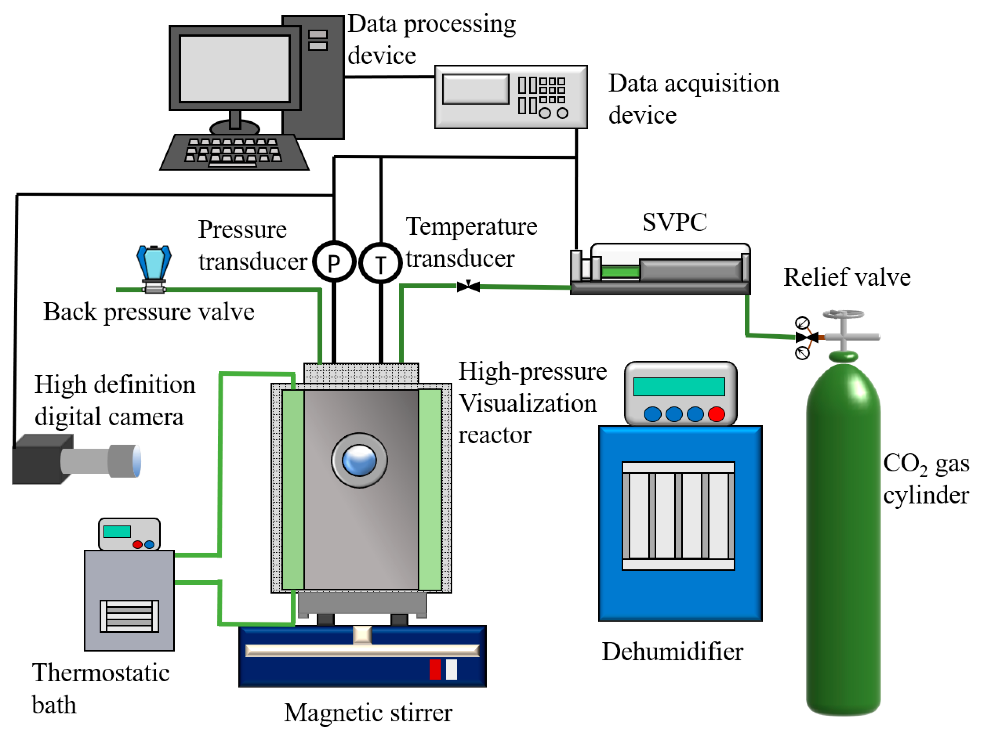
The experiments in this study were conducted primarily using a self-developed high-pressure and low-temperature visualization hydrate reaction system, as shown in Figure 2. The system primarily consists of a temperature control system, a gas–water injection system, an in situ hydrate formation system, and a visualization data acquisition system. The temperature control system is primarily composed of an insulated jacket, a platinum resistance PT-100 temperature sensor (Heraeus, Hannover, Germany), and a DC-1006 cooling bath (Jingru Trading Co., Ltd., Wenzhou, China). Ethylene glycol solution is employed as the coolant, with a temperature control range of −20 °C to +40 °C and a precision of 0.05 °C. The gas–water injection system primarily comprises gas cylinders, a water tank, a pressure-reducing valve (manufactured by Lightinglok, Taipei, China), a high-precision SVPC plunger pump (Xi’an Kontuo Instrument Equipment Co., Ltd., Xi’an, China), sealed pipelines, ball valves, pressure sensors, a vacuum pump, and a back-pressure valve. The maximum pressure is 16 MPa, with a precision of 0.001 MPa. The in situ hydrate formation visualization system comprises a high-pressure visualization reactor made of 316 stainless steels, an SR-MS-M precision magnetic stirrer (Changzhou Surui Instrument Co., Ltd., Changzhou, China), a dehumidifier, and a water tank. The reactor has an internal diameter of 60 mm and a height of 100 mm, with a sapphire window measuring 25 mm in diameter located at the central section. The visualization data acquisition system comprises an acA4024-8 gc industrial camera (BASLER, Arensburg, Germany), a KM-2 FL5050 planar light source, and an OHR-A303 data acquisition and processing unit. All experimental data, including pressure, temperature, and images, are transmitted in real-time to a computer via the data acquisition system, thereby facilitating subsequent data processing and analysis. The system is capable of synchronously collecting multiple parameters, thereby ensuring the integrity and high accuracy of the experimental data.
The primary materials employed in the experiments comprised CO2 gas, deionized water, an L-tryptophan chemical promoter solution, and artificially fabricated sandstone fractures. CO2 gas, with a purity of 99.99%, was provided by Xuzhou Luyou Co., Ltd. (Xuzhou, China). Deionized water was generated in-laboratory to reduce the influence of soluble impurities on CO2 hydrate formation. A 1.0 wt% L-tryptophan solution was formulated by dissolving high-purity L-tryptophan powder (≥99%) in deionized water under controlled conditions to ensure homogeneity. The I-type and X-type fractures with different apertures required in the experiment are custom-made artificial products. The main components are quartz sand (50.6%), low-sodium feldspar (21.2%), kaolinite (14.3%), and biotite (13.9%). The compressive strength is 65 MPa, and the density is 2.38 g/cm3. The surface roughness of the fracture walls was regulated by affixing glass sand particles of various grain sizes, enabling the modulation of the wall-specific surface area and consequently affecting hydrate nucleation and growth behavior.

2.2. Experimental Procedures and Schemes

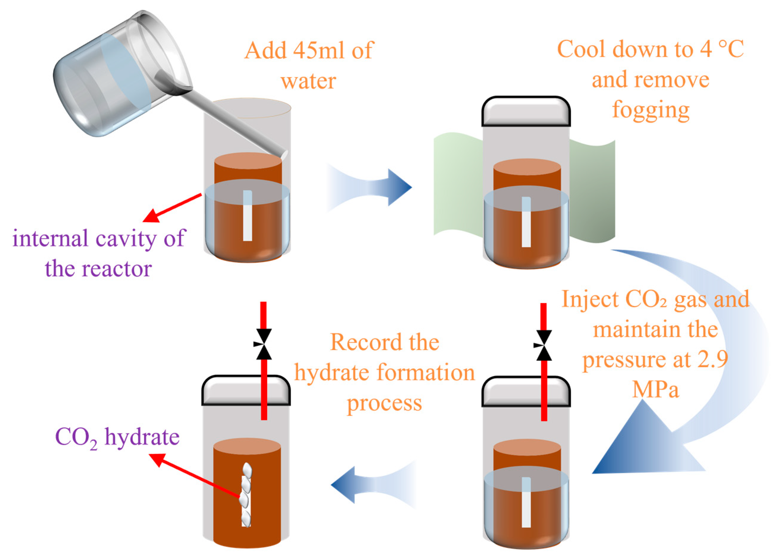
The experimental procedures for CO2 hydrate formation, dissociation, and reformation conducted in this study were executed as follows: (1) A series of preliminary experiments established that maintaining a liquid volume of 45 mL within the sandstone fractures is optimal for visualizing hydrate growth trajectories via a high-definition camera. Under these conditions, a gas-to-liquid ratio of 1:3 was maintained. (2) Prior to the experiment, clean the reactor and sapphire window with deionized water three times to ensure cleanliness and residue-free surfaces. (3) Install the sandstone fracture into the reactor, measure 45 mL of deionized water, and slowly pour it into the fracture using a glass rod. (4) Seal the reactor. Then, activate the cooling bath to lower the temperature to 4 °C. (5) CO2 gas was injected into the reactor using a plunger pump and maintained at a pressure of 2.9 MPa. Data recording and image acquisition were initiated simultaneously. (6) Once the volume displayed by the SVPC plunger pump remained stable for 30 min, it was concluded that CO2 consumption had ceased, indicating the completion of CO2 hydrate formation. (7) The pressure in the SVPC plunger pump and the reactor was quickly reduced to 0.7 MPa to initiate hydrate dissociation. The system was monitored until the plunger pump volume remained stable for 30 min, at which point hydrate dissociation was considered complete. (8) CO2 gas was then re-injected into the reactor using the plunger pump to raise the pressure back to 2.9 MPa, inducing hydrate reformation. The process continued until the plunger pump volume stabilized, signifying the completion of the experiment. A concise experimental flow chart is shown in Figure 3.
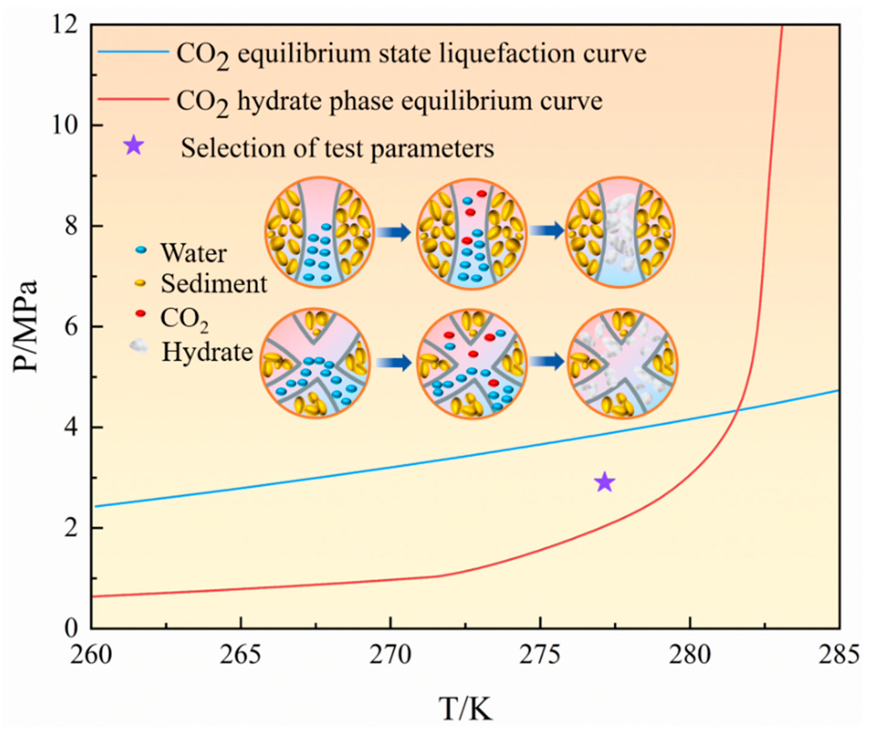
In the experimental study of CO2 hydrate formation within fractures, three primary factors were considered: fracture type, width, and surface roughness. Investigations of seabed sediments in the South China Sea have found that fractures in the actual reservoir vary greatly in size and shape, exhibiting significant complexity [40]. Additionally, based on the X-ray scanning results of sediment cores by Rees et al. [41], the average aperture of the main fractures is 6 mm. Therefore, the fracture type was simplified into two representative types: I-type and X-type. Three distinct widths: 3 mm, 6 mm, and 10 mm, were selected, along with three levels of surface roughness: smooth, medium (2.5 mm glass sand), and rough (3.5 mm glass sand). Taking into account the geothermal gradient, the liquefaction points of CO2, and the phase equilibrium conditions for CO2 hydrate formation (as shown in Figure 4), the experimental temperature was maintained at 4 °C, and the formation pressure was set to 2.9 MPa. The chemical promoter L-tryptophan was used at a concentration of 1.0 wt% and a stirring rate of 500 rpm. The detailed experimental parameters are summarized in Table 1.
Based on the gas consumption curves and images obtained during the experiments, the primary parameters analyzed include the induction time of CO2 hydrate formation, the duration of hydrate growth, the total hydrate yield, and the visual characteristics of hydrate formation within the fractures. Among these parameters, the induction period was defined as the time interval between the initiation of stirring and the moment when significant gas consumption was observed in the SVPC plunger pump. The start of stirring marked the beginning of the induction period, while the onset of noticeable gas consumption signaled its end. The actual hydrate yield was calculated using the Van Der Waals equation of state for real gases, as shown in Equation (1).
n = ( P 0 Z 0 P t Z t ) × V g R T
where n denotes the amount of consumed gas (in mol), P0 represents the initial system pressure, Pt is the system pressure at time t, Z0 denotes the compressibility factor of CO2 at P0, and Zt is the compressibility factor at Pt, both derived from the NIST Standard Reference Database. T represents the experimental temperature, R is the universal gas constant (8.314 J/(mol·K)), and Vg is the gas volume in the reactor, determined to be 6.98 × 10 −5 m3.

3. Results and Discussion

3.1. Kinetics and Morphology of CO2 Hydrate Formation Within Fractures

3.1.1. Effect of Fracture Width

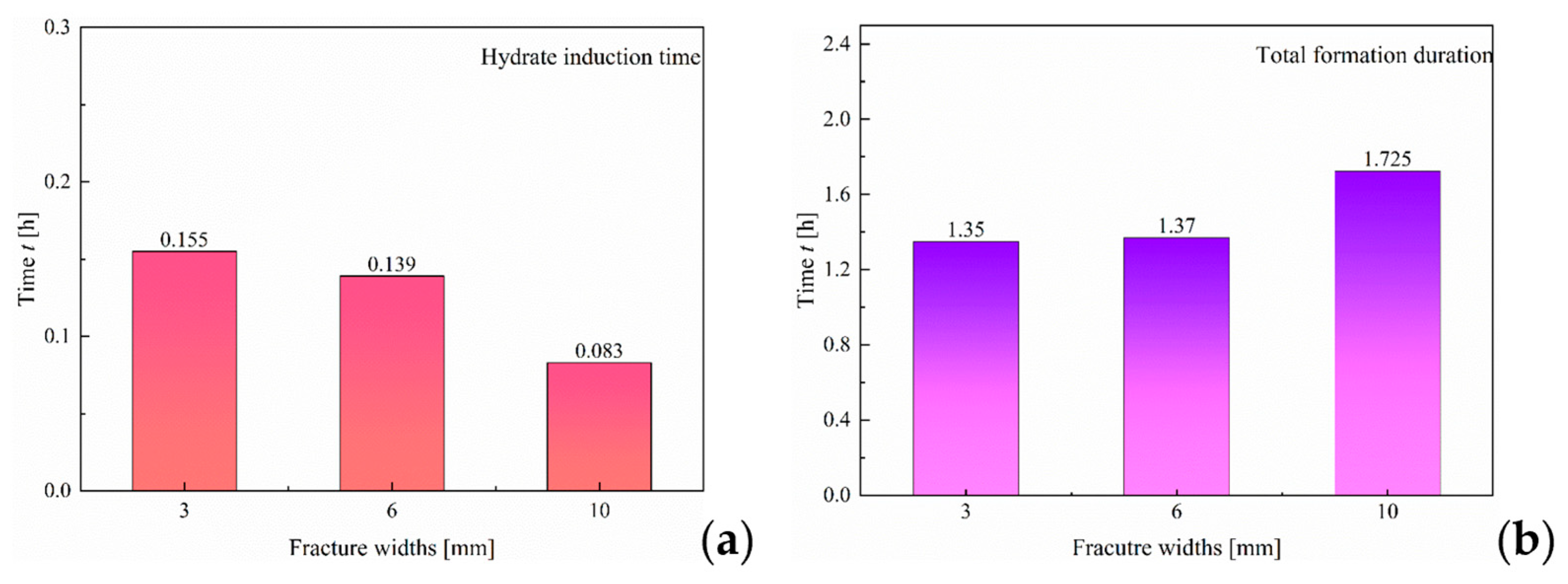
Figure 5 illustrates the induction time and formation duration of CO2 hydrate under varying width sizes of I-type fractures. It can be observed that, at a pressure of 2.9 MPa, the induction time for hydrate formation shows a negative correlation with fracture width. As the width increases from 3 mm to 10 mm, the induction time decreases from 0.155 h to 0.083 h, representing a reduction of approximately 46%. This phenomenon may be attributed to the larger fracture width, which increases the gas–liquid contact area, allowing CO2 to dissolve more rapidly in water and thereby providing more nucleation sites. Moreover, an increase in fracture width reduces capillary pressure and enhances convective flow, resulting in a more abundant supply of gas and a more uniform temperature distribution within the fractures. These factors collectively promote the nucleation process of CO2 hydrate formation within the fractures.
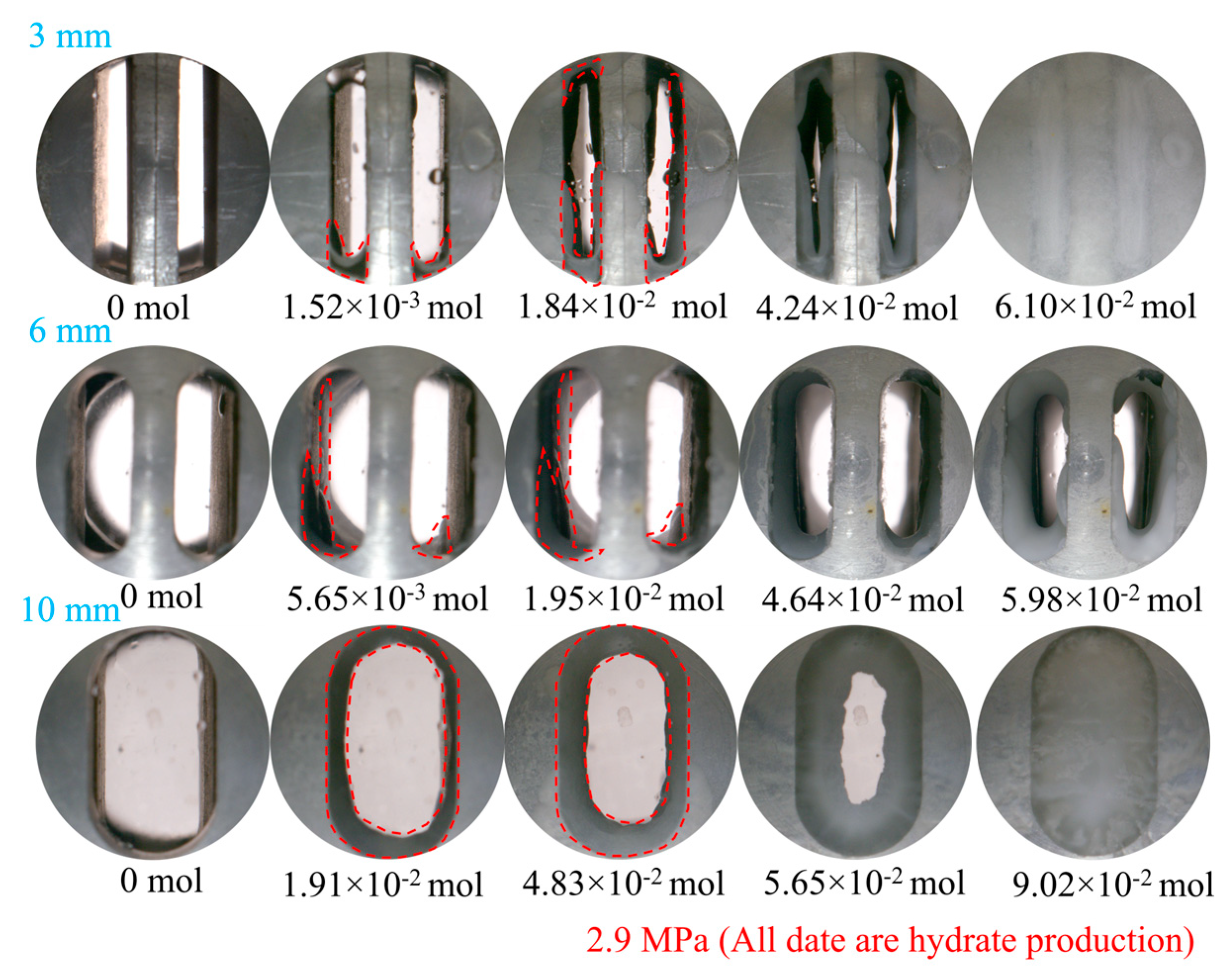
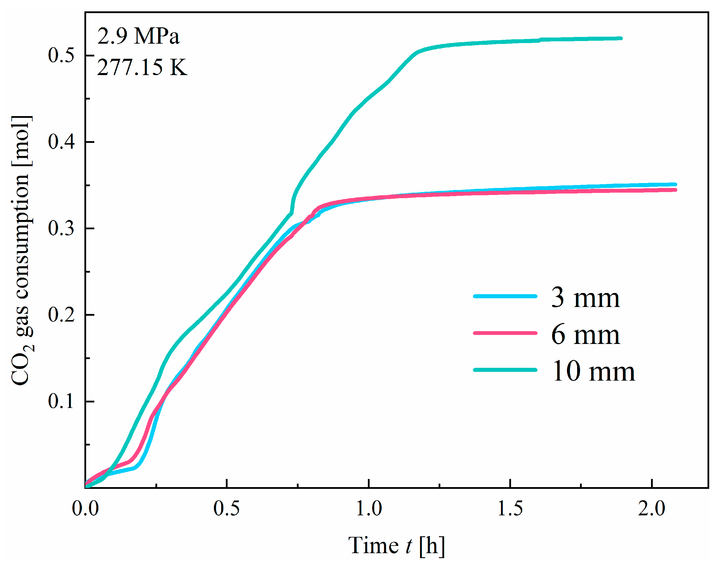
Upon observing the hydrate formation duration (Figure 5b), it was found that, under a pressure of 2.9 MPa, the formation durations of CO2 hydrates in fractures with widths of 3 mm and 6 mm were nearly identical. However, it is noteworthy that the hydrate formation duration increases significantly in the fracture with a 10 mm width. This may be attributed to the fact that, at 2.9 MPa, the hydrate formation rate is moderate for a 10 mm fracture aperture, and, as shown in Figure 6, the resulting hydrate morphology appears smoother. The smoother surface likely enhances the diffusion resistance between the CO2 and water molecules inside the hydrate shell, thereby increasing the time required for complete hydrate formation. As shown in the gas consumption curves in Figure 7, the aforementioned hypothesis can be further validated. In this case, the hydrate yield increases significantly, leading to a prolonged formation duration. Under a pressure of 2.9 MPa, as the CO2 solubility and diffusion rate increase, the influence of fracture width on gas consumption becomes dominant. Consequently, a positive correlation is observed between cumulative gas consumption and fracture width.
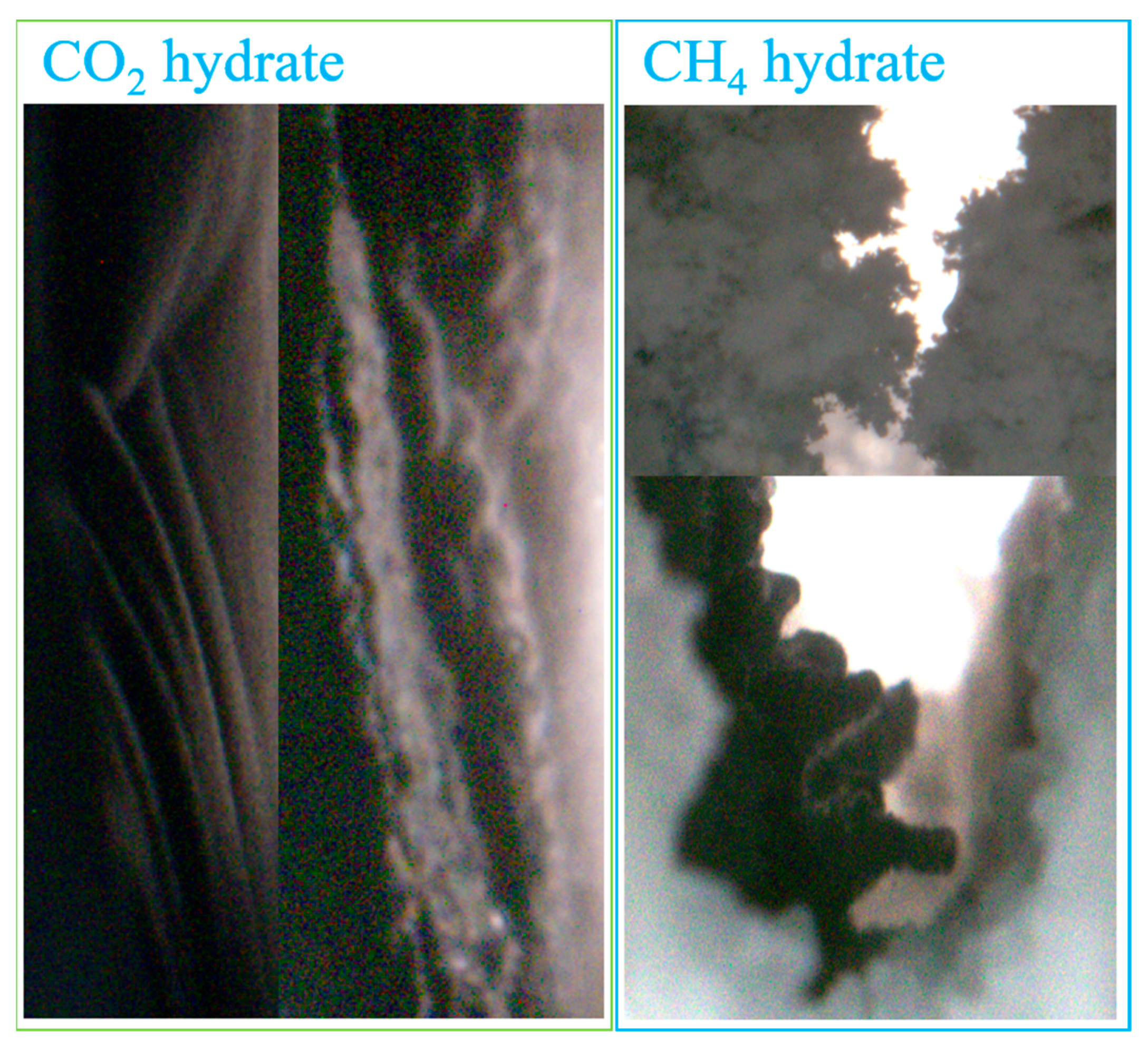
Further observation of the growth morphology of CO2 hydrates under different fracture widths, as shown in Figure 6, reveals that, similar to CH4 hydrate formation, width size does not significantly influence the morphological characteristics of CO2 hydrate growth [42]. In all cases, hydrates preferentially form along the fracture walls and gradually spread to surrounding regions. Eventually, a continuous hydrate film forms across the entire wall surface, followed by gradual inward expansion into the fracture space. Compared to the morphology of the CH4 hydrates formed in the experiment by Ma et al. [42], as illustrated in Figure 8, CO2 hydrates exhibit a growth morphology characterized by wave-like, smooth, and gently sloping thin walls. Although certain areas may exhibit uneven textures with protrusions and indentations, the overall trend remains smooth and gradual. In contrast, CH4 hydrates exhibit a dense, fibrous appearance, often accompanied by irregular branches and crystalline structures under high-pressure conditions. This results in a generally rough, loose, and irregular growth pattern. The observed differences in hydrate morphology may be attributed to the distinct molecular properties and solubility of the guest gases. CO2 molecules are relatively smaller and exhibit greater solubility in water than CH4 molecules. Under appropriate conditions, this enables CO2 molecules to dissolve more readily into the aqueous phase and to diffuse uniformly throughout the liquid, thereby facilitating homogeneous nucleation and growth. Moreover, the weaker intermolecular forces between CO2 molecules promote the formation of a uniform hydrate layer, which subsequently develops into a smooth and well-defined morphology. In contrast, CH4 molecules are comparatively larger and exhibit lower solubility in water, thereby complicating the hydrate formation process. During the initial stage of formation, the slower diffusion rate of CH4 may result in the development of irregular local structures on the surface. Under high-pressure conditions, hydrate growth becomes more vulnerable to external factors, such as interfacial effects and temperature gradients, leading to a more disordered growth pattern. Furthermore, the stronger intermolecular forces between CH4 molecules contribute to a looser association between gas and water molecules during hydrate formation, ultimately resulting in the formation of irregular, fibrous, and loosely packed structures.

3.1.2. Effect of Fracture Type

As observed from the CO2 gas consumption curves under various fracture geometries and widths (Figure 9), the formation of CO2 hydrates in I-type fractures is characterized by a distinct induction period. In contrast to the I-type fractures, where CO2 hydrate formation exhibits a distinct induction period, hydrate formation in the X-type fractures occurs with almost no observable induction time, indicating that the induction and dissolution processes proceed simultaneously. This difference is likely due to the distinct fracture geometries. The I-type fractures have a relatively simple and stable structure with a limited gas–liquid interfacial area, which restricts the dissolution of CO2 molecules into the aqueous phase, consequently leading to a prolonged induction period. In comparison, the X-type fractures feature multiple interconnected cross-flow channels, significantly enhancing the mixing efficiency between gas and water, thereby expanding the gas–liquid contact interface. Combined with the inherently high solubility of CO2 in water, this facilitates the rapid dissolution of CO2 and its immediate participation in hydrate formation. As a result, the processes of dissolution and nucleation are effectively synchronized in the X-type fractures.
As shown in Table 2, the duration of hydrate formation under different width sizes in X-type fractures indicates that, at a pressure of 2.9 MPa, the formation time is shorter in X-type fractures compared to I-type fractures. This may be attributed to the fact that, under these pressure conditions, both gas dissolution and hydrate induction in X-type fractures occur within a favorable “comfort zone”. Consequently, hydrates form rapidly, resulting in pore space blockage and disruption of gas mass transfer. This significantly reduces the duration of the hydrate formation process and results in a lower overall hydrate yield compared to I-type fractures. Furthermore, it was observed that the hydrate formation duration in X-type fractures does not display a clear trend with varying width sizes, which contrasts with the behavior observed in I-type fractures. This suggests that the presence of multiple flow channels in X-type fractures diminishes the influence of fracture width on hydrate formation dynamics.
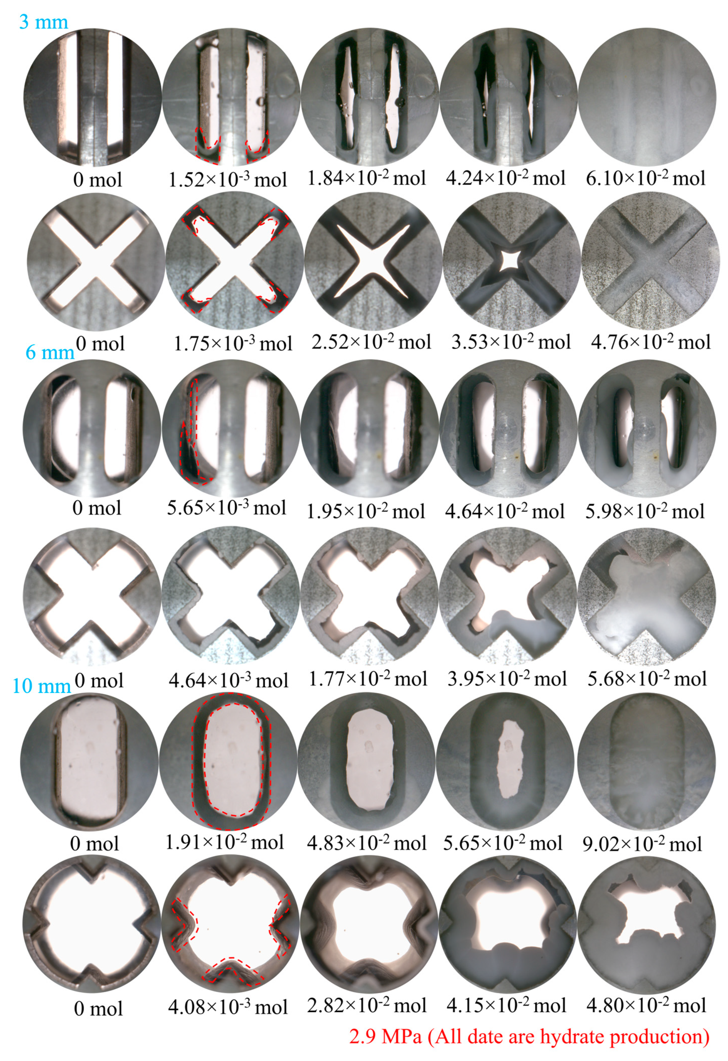
As shown in Figure 10, CO2 hydrates within the fractures exhibit a dense and smooth morphology, with the growth pattern primarily indicating expansion in multiple directions toward the central region. In I-type fractures, when the roughness is 3 mm or 6 mm, CO2 hydrates tend to form initially at the lower part of the fracture and gradually propagate toward the center. In contrast, at a 10 mm roughness, hydrate growth begins simultaneously from multiple directions and progresses inward toward the center. In comparison, in X-type fractures, regardless of roughness, CO2 hydrates consistently exhibit a growth pattern converging from all directions toward the central region. These observations suggest that CO2 hydrates exhibit greater structural stability under suitable thermodynamic conditions. Such stability not only enhances the feasibility of CO2 hydrate formation in fractured media but also provides valuable insights and theoretical support for the development of hydrate-based carbon capture and sequestration (CCS) strategies.

3.1.3. Effect of Roughness

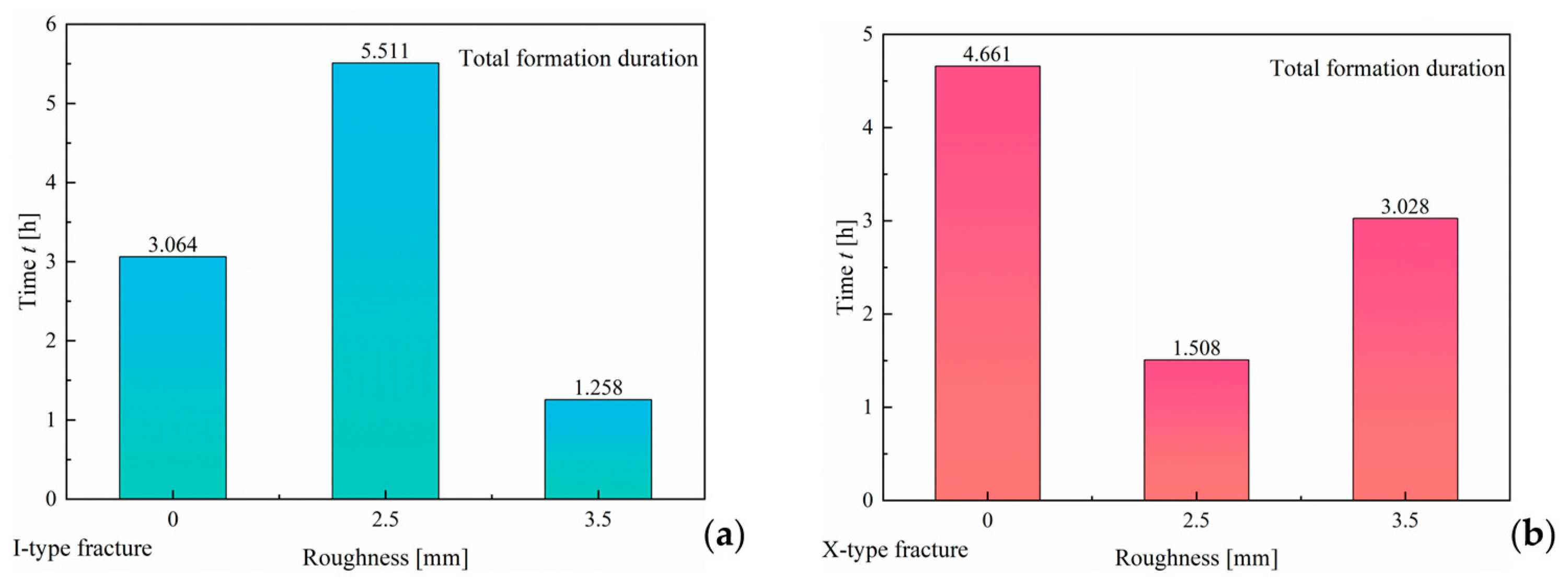
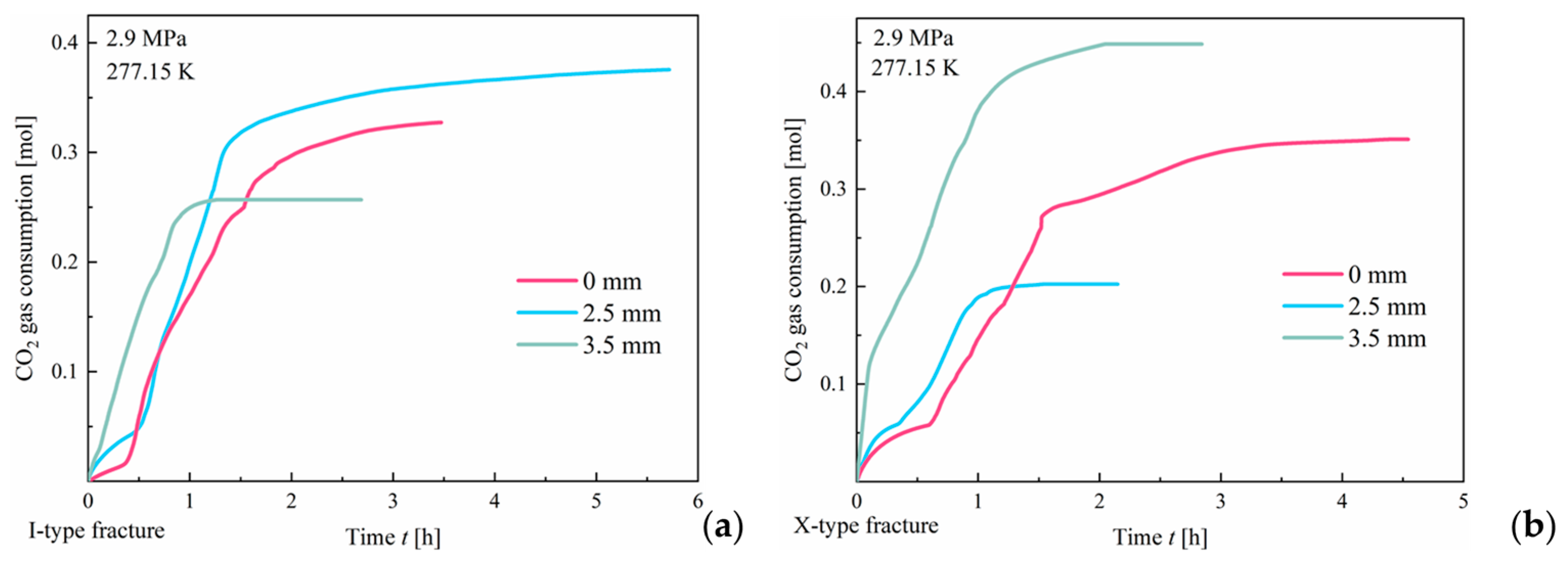
Following an increase in fracture roughness, the induction time for CO2 hydrate formation in both I-type and X-type fractures becomes nearly negligible. This suggests that an increase in roughness enhances the number of potential nucleation sites, thereby facilitating the interaction between gas and liquid molecules and accelerating hydrate formation. Further analysis of the hydrate formation duration and final hydrate yield (as shown in Figure 11 and Figure 12) reveals that, in I-type fractures, both parameters display a clear trend: fractures with greater roughness show the longest formation duration and the highest final hydrate yield, followed by smooth fractures, while fractures with lesser roughness exhibit the shortest duration and lowest yield. Based on the fundamental principles of fluid dynamics and interfacial reactions, it can be concluded that fracture roughness plays a significant role in hydrate formation. Increased surface roughness typically corresponds to a larger specific surface area and more microstructural irregularities, both of which facilitate the nucleation and adhesion of hydrate crystals. These features offer more favorable sites for the initial attachment and growth of hydrates, thereby enhancing the overall formation efficiency. Compared to smooth fractures, rough fractures offer more active sites and higher surface energy, which can promote the hydrate formation process. Therefore, in I-type fractures, those with larger specific surface areas present more favorable conditions for hydrate formation, resulting in longer formation durations and higher final hydrate yields. Additionally, the more complex geometry of rough fracture surfaces can impede fluid flow within the fractures, potentially prolonging the duration of hydrate formation. In contrast, in smooth fractures, liquid migration is primarily driven by capillary action along the fracture walls, with fewer active sites available for hydrate nucleation and growth, leading to a lower overall hydrate yield. Therefore, the hydrate formation behavior in I-type fractures is influenced, to some extent, by the effects of fracture surface roughness on the fluid flow dynamics and interfacial reaction rates.
Unlike the hydrate formation trend observed in I-type fractures, the duration of hydrate formation in X-type fractures revealed that smooth fractures exhibited the longest formation duration, followed by fractures with a smaller specific surface area (3.5 mm particle size), whereas those with a larger specific surface area (2.5 mm particle size) had the shortest formation duration. This is consistent with the conclusions above, indicating that fracture roughness significantly promotes the induction and growth rates of hydrates.
However, when examining the final hydrate yield, discrepancies were observed. Although smooth fractures exhibited the longest hydrate formation duration, the final hydrate yield was comparatively low. This may be attributed to the fact that, while smooth surfaces provide a more stable environment supporting prolonged hydrate growth, the lack of microscale roughness limits the availability of nucleation sites, thereby slowing the initial formation of hydrate crystals. Therefore, despite the longer formation time, the hydrate yield did not increase significantly, as shown in Figure 12, where the hydrate formation rate in smooth fractures slows considerably in the later stages. In comparison, fractures with moderate roughness not only provide localized irregularities on the fracture walls that promote hydrate nucleation and attachment but also maintain a more favorable fluid disturbance regime for hydrate formation. Unlike highly rough fractures, where the flow may be excessively disrupted or unevenly distributed, moderately rough fractures allow for better gas–liquid mixing and transport without causing excessive flow instability. As a result, the final hydrate yield in these fractures exceeds that observed in both smooth and highly rough fractures.
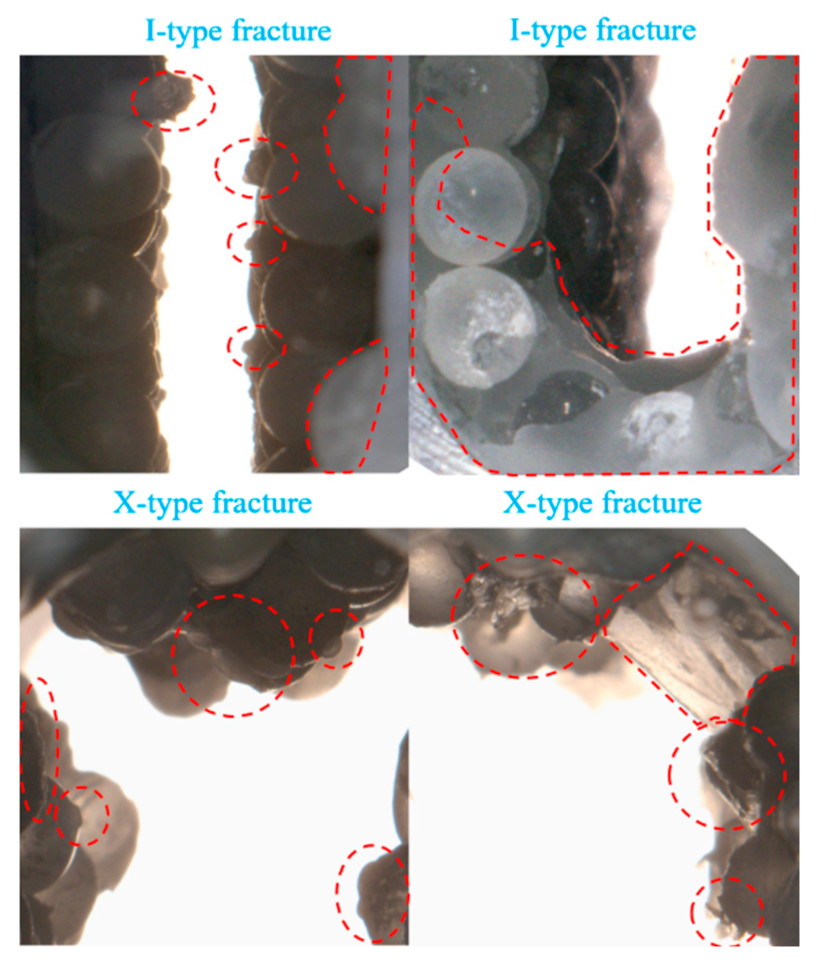
Upon observing the morphological characteristics of CO2 hydrate formation in rough fractures (as illustrated in Figure 13), it was observed that rough fractures with protruding areas are more prone to form nucleation sites compared to smooth fractures, thus promoting hydrate formation. Gas flow in X-type fractures is inherently unstable. As the specific surface area of the fractures increases, the instability is amplified, leading to more erratic gas flow and interaction with water molecules. In some localized regions, gas may accumulate or flow dead zones may form. Furthermore, X-type fractures contain more nucleation sites, leading to a more disordered distribution of hydrates. Additional observations revealed that CO2 hydrates typically fill the spaces between glass sand grains in a compact manner. This suggests that CO2 hydrates in natural reservoirs can effectively cement and fill the soil particle framework, thus enhancing the stability of the reservoir.

3.2. Dissociation Kinetics and Morphological Characteristics of CO2 Hydrates Within Fractures

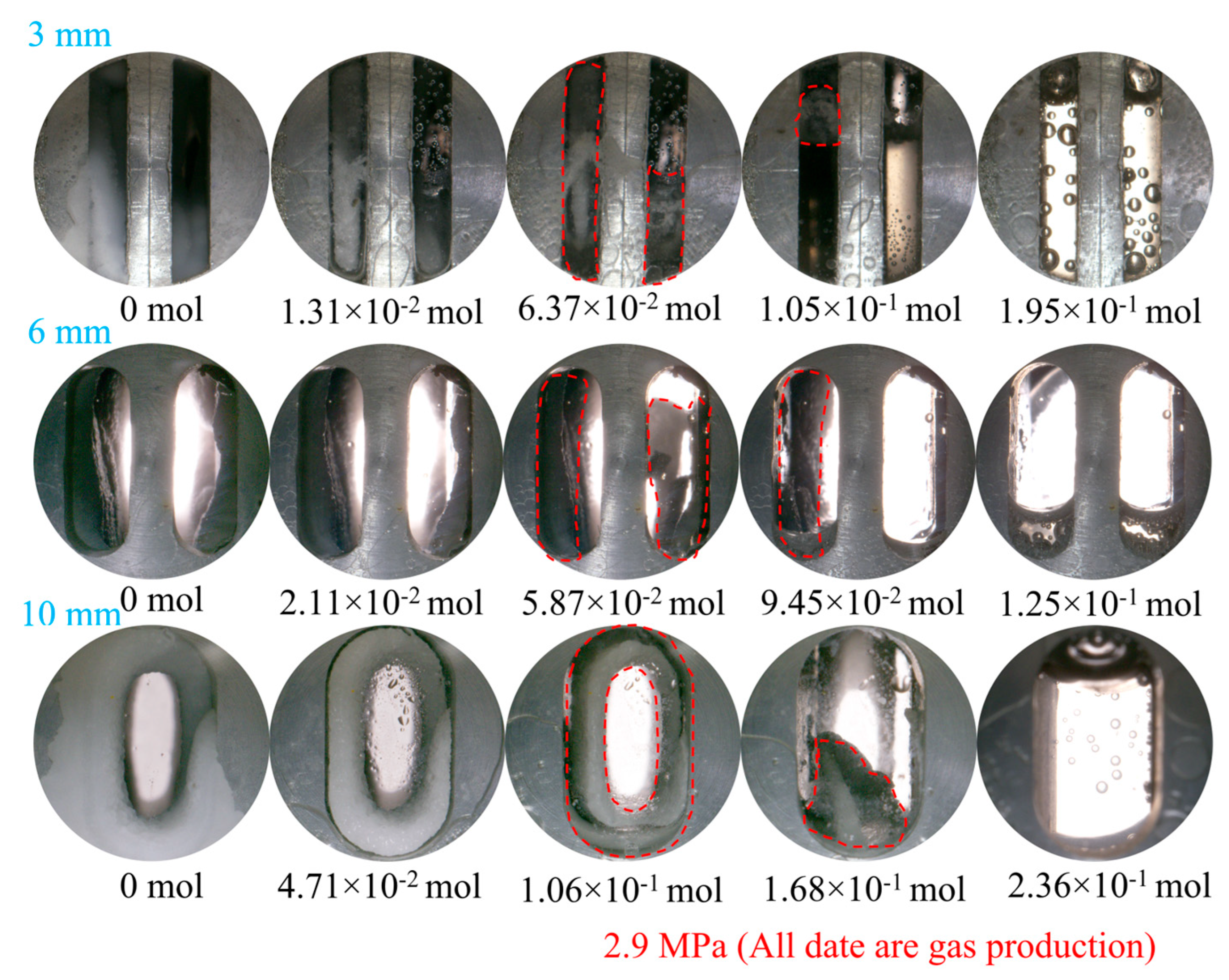
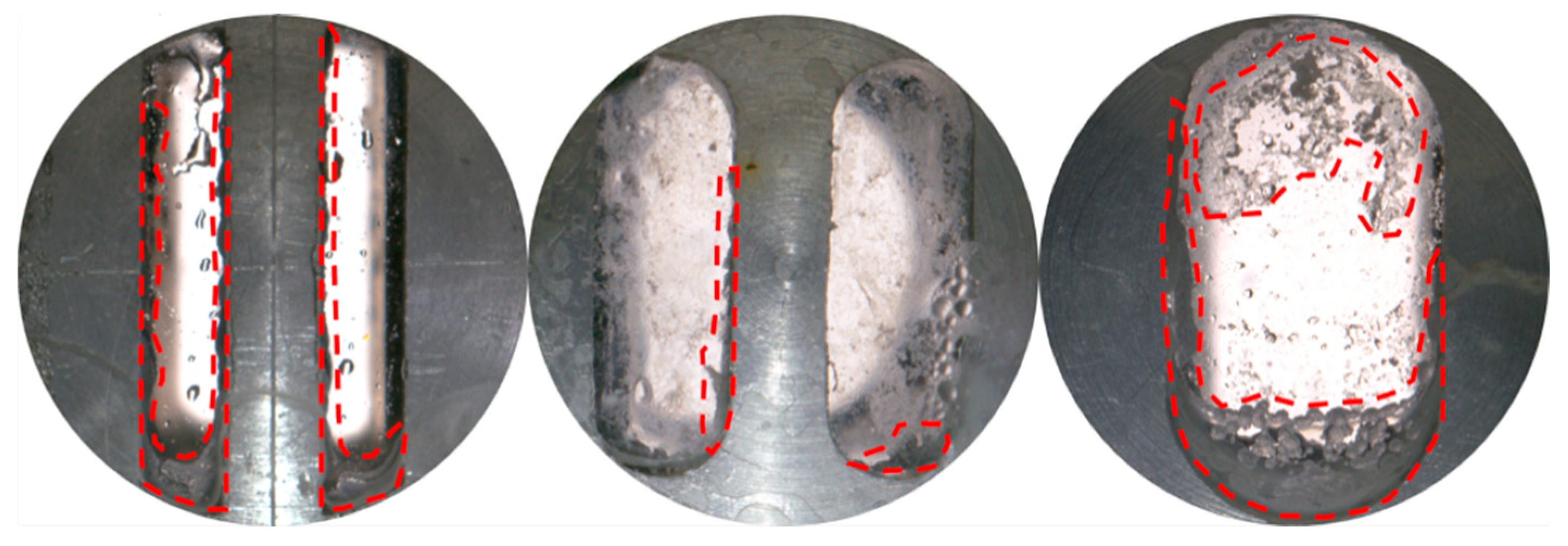
Figure 14 illustrates visual observations of CO2 hydrate dissociation via depressurization at varying fracture widths. Analysis suggests that CO2 hydrate dissociation initiates at the sandstone wall surface, where heat causes the hydrate to dissociate from the wall and subsequently propagate inward until full dissociation occurs. At a pressure of 2.9 MPa, as the fracture width increases, heat transfer in the 10 mm-wide fracture reaches an optimal state, leading to the highest gas production of 0.24 mol.
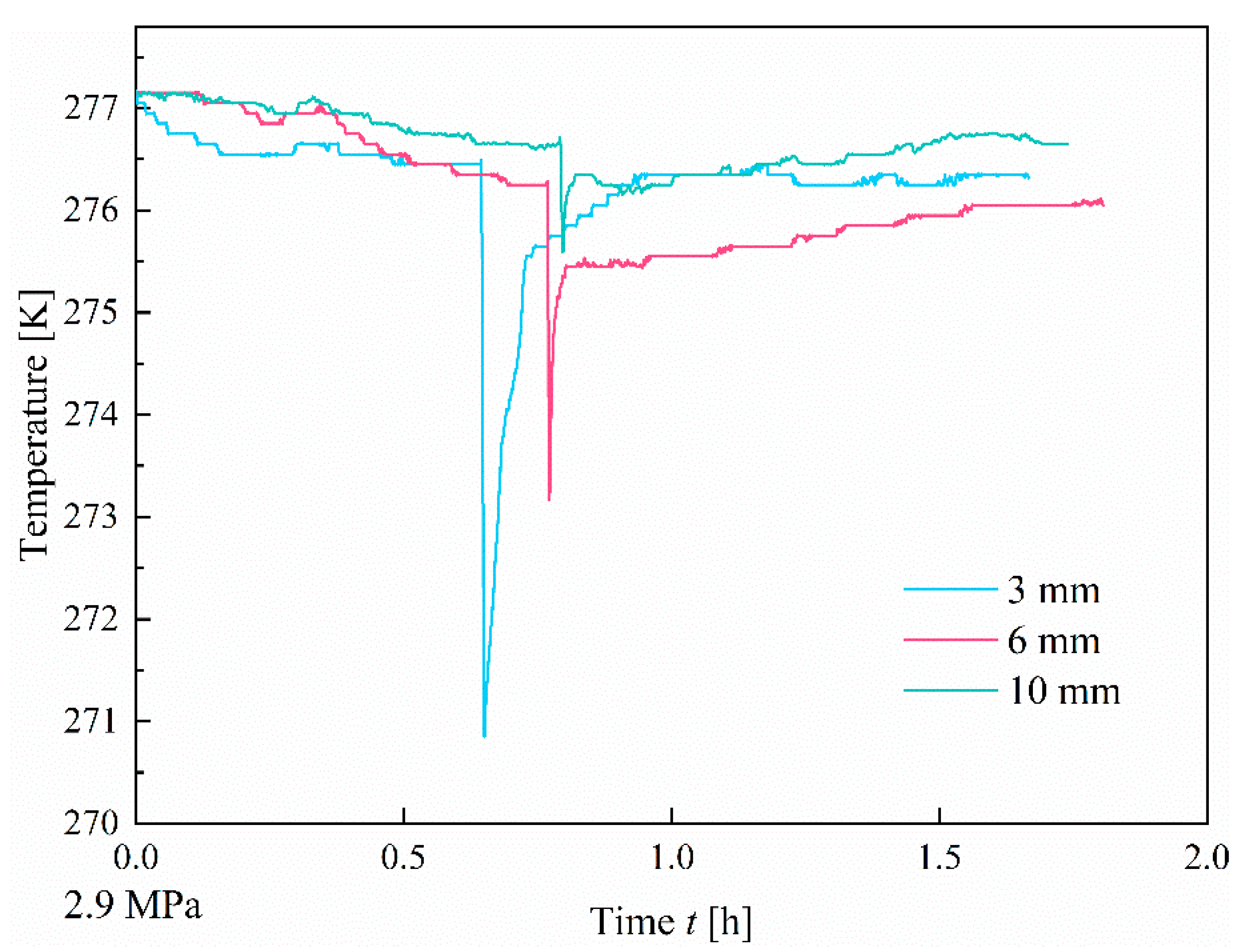
Observations of temperature changes during the dissociation period, as shown in Figure 15, reveal that the temperature initially drops rapidly during CO2 hydrate dissociation, followed by a gradual increase until stabilization occurs. This behavior is attributed to the endothermic nature of the hydrate dissociation process. Interestingly, in contrast to the 6 mm and 10 mm fissure widths, the 3 mm fissure exhibits a temperature that fluctuates around or even exceeds the initial dissociation temperature (277.15 K) during the gradual phase of temperature increase. This phenomenon is likely due to the smaller fissure width restricting the diffusion of released gases, causing the gases to backfill and increasing local pressure. Such an increase in pressure could lead to hydrate reformation, releasing heat in the process, which may account for the observed temperatures exceeding the initial temperature.

3.3. Hydrate Reformation

By calculating and comparing the induction times during the initial and hydrate reformation stages, it can be found that the induction time for the hydrate-first formation was significantly longer than that for the subsequent reformation across all experimental conditions. The induction times for hydrate reformation were negligible in all cases. This observation is consistent with prior studies [43]. This phenomenon may be attributed to the presence of residual hydrate nuclei remaining at their original locations post-dissociation. During the reformation stage, these residual nuclei may be reactivated, thereby triggering rapid hydrate reformation [44]. As shown in Figure 16, hydrates preferentially form in the regions where they were previously located. This behavior aligns with the so-called “memory effect” of gas hydrates described in prior studies [45].
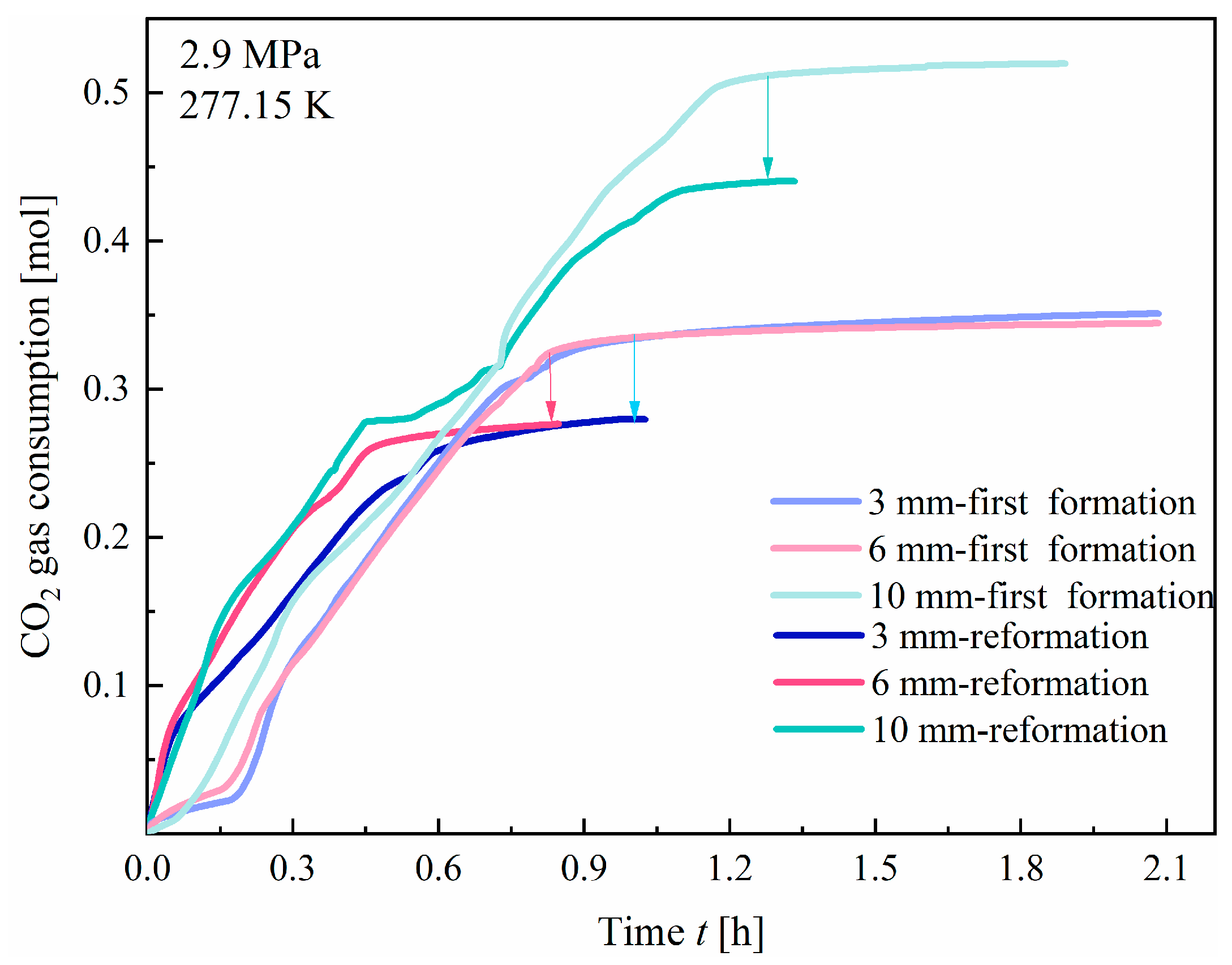
Furthermore, by examining the CO2 gas consumption curves in Figure 17, it can be observed that the hydrate formation rate during the reformation stage is faster than that during the initial formation stage under all experimental conditions. This phenomenon can be attributed to two primary factors. On one hand, it may be influenced by the aforementioned “memory effect”, where residual hydrate nuclei facilitate rapid reformation. Conversely, it is likely that more dissolved gas remains in the liquid phase following depressurization and dissociation. When the system is subsequently heated to initiate hydrate reformation, the increased concentration of dissolved gas enhances the interactions between gas and water molecules, thereby accelerating hydrate formation kinetics. Furthermore, hydrate dissociation may alter the surface tension and free energy of the liquid in the system, thus facilitating more efficient interactions with gas molecules, which aids in the formation of stable hydrate structures. A further comparison of the gas consumption curves for the initial and CO2 hydrate reformation reveals that, under identical conditions, the final yield of hydrates formed during the initial formation is consistently greater than that formed during the reformation. This can be attributed to the high solubility of CO2 in water, which enables a relatively high hydrate yield during the initial formation stage. During the subsequent dissociation process, however, some residual nuclei may become deactivated, inhibiting the adsorption of gas molecules on the surface and consequently reducing the hydrate formation capacity during the reformation stage. Consequently, the yield of hydrate formed in the second cycle is consistently lower than that formed during the initial cycle.
Based on the preceding discussion, the research findings presented here offer significant theoretical guidance for large-scale on-site CO2 hydrate sequestration. First, the aperture and morphology of fractures play a significant role in affecting the hydrate formation rate and total production. Optimizing the reservoir fracture structure or selecting appropriate CO2 injection strategies can greatly enhance hydrate formation efficiency. Second, the kinetic data on hydrate formation provide key parameters for large-scale CO2 hydrate sequestration models. This aids in improving the accuracy and reliability of on-site sequestration simulations. Therefore, this study provides a theoretical foundation for evaluating the feasibility and advancing the technology of CO2 hydrate sequestration in practical applications. It also establishes a solid foundation for future research and engineering practices related to CO2 hydrate sequestration.

4. Conclusions

This study was primarily conducted with in situ formation experiments on CO2 hydrates within sandstone fractures. During the CO2 injection process, the Joule–Thomson effect causes changes in the pore structure of the formation during the hydrate formation process. By analyzing the induction time, formation duration, and morphological characteristics of hydrates under varying fracture widths, types, and surface roughness conditions, the morphology and influencing factors of hydrate formation were systematically investigated. The main conclusions are presented as follows.
(1)
At a pressure of 2.9 MPa, the induction time of CO2 hydrates is inversely correlated with fracture width. In comparison to the other two width sizes, the 10 mm width fracture exhibits the shortest induction time, the longest formation duration, and the highest hydrate yield (approximately 0.52 mol). In contrast to the irregular, flocculent morphology of CH4 hydrates, CO2 hydrates predominantly exhibit a smooth, flat, thin-wall structure. This morphological characteristic remains consistent, regardless of variations in fracture width;
(2)
The X-type fracture facilitates gas flow, enabling CO2 dissolution and hydrate induction to occur nearly simultaneously. Hydrate formation is controlled by both the formation rate and the total available space. In comparison to the I-type fracture, the X-type fracture exhibits a shorter hydrate formation duration. Furthermore, due to interface clogging, the final hydrate yield in X-type fractures is ultimately limited;
(3)
An increase in fracture surface roughness enhances the number of nucleation sites for hydrate formation. In both fracture types, the induction time for CO2 hydrate formation is nearly negligible. However, a significant difference is observed in the progression of formation duration under varying roughness conditions. In I-type fractures, the hydrate formation duration gradually increases with increasing surface roughness. In contrast, in X-type fractures, the formation duration decreases as the roughness increases. However, in both fracture types, an increase in roughness does not significantly affect the final hydrate yield;
(4)
Hydrate dissociation exhibits a diffusion pattern from the fracture surface toward the interior, with residual hydrates displaying an uneven, wavy morphology. Gas production is influenced by fracture width. Among the tested widths, the 10 mm fracture yielded the highest gas volume, reaching approximately 0.24 mol;
(5)
The reformation of hydrates exhibits a “memory effect” that significantly reduces the induction time compared to that of the initial formation. However, due to the high solubility of CO2 in water, the hydrate yield during reformation remains consistently lower than that of the first formation.
During CO2 injection into sediments, the Joule–Thomson effect causes some of the CO2 to convert into hydrates. This leads to changes in the sediment pore structure and may trigger fracture formation. Due to the limitations of the research conditions, the results presented in this study may be somewhat conservative. Nevertheless, this study investigates how fracture aperture, shape, and roughness affect CO2 hydrate formation kinetics and morphology. The aim is to provide theoretical support for CO2 seabed sequestration using the hydrate method.

Author Contributions

Conceptualization, T.L.; methodology, C.M. (Chuanhe Ma), J.W. and T.L.; formal analysis, T.H., Z.D. and C.M. (Chaozheng Ma); writing—original draft preparation, C.M. (Chuanhe Ma) and H.S.; writing—review and editing, H.S., J.W. and T.L.; supervision, T.H., Z.D. and C.M. (Chaozheng Ma). All authors have read and agreed to the published version of the manuscript.

Funding

This study was supported by the Foundation Research Project of Xuzhou (Grant No. KC22061), Graduate Innovation Program of China University of Mining and Technology (Grant No. 2025WLJCRCZL057) and the Postgraduate Research & Practice Innovation Program of Jiangsu Province (Grant No. SJCX25_1377).

Institutional Review Board Statement

Not applicable.

Informed Consent Statement

Not applicable.

Data Availability Statement

The original contributions presented in this study are included in the article. Further inquiries can be directed to the corresponding author.

Conflicts of Interest

Author Hongxiang Si was employed by Xinwen Mining Group Co., Ltd. The remaining authors declare that the research was conducted in the absence of any commercial or financial relationships that could be construed as a potential conflict of interest.

References

  1. United Nations Environment Programme. Emissions Gap Report 2023: Broken Record–Temperatures Hit New Highs, yet World Fails to Cut Emissions (Again); Knowledge Repository–UNEP: Nairobi, Kenya, 2023. [Google Scholar]
  2. Ma, Z.W.; Zhang, P.; Bao, H.S.; Deng, S. Review of Fundamental Properties of CO2 Hydrates and CO2 Capture and Separation Using Hydration Method. Renew. Sust. Energ. Rev. 2016, 53, 1273–1302. [Google Scholar] [CrossRef]
  3. Zheng, J.; Chong, Z.R.; Qureshi, M.F.; Linga, P. Carbon Dioxide Sequestration via Gas Hydrates: A Potential Pathway toward Decarbonization. Energy Fuels 2020, 34, 10529–10546. [Google Scholar] [CrossRef]
  4. Brook, R.D.; Rajagopalan, S.; Pope, C.A., III; Brook, J.R.; Bhatnagar, A.; Diez-Roux, A.V.; Holguin, F.; Hong, Y.; Luepker, R.V.; Mittleman, M.A.; et al. Particulate matter air pollution and cardiovascular disease an update to the scientific statement from the American heart association. Circulation 2010, 121, 2331–2378. [Google Scholar] [CrossRef]
  5. Amstrup, S.C.; DeWeaver, E.T.; Douglas, D.C.; Marcot, B.G.; Durner, G.M.; Bitz, C.M.; Bailey, D.A. Greenhouse gas mitigation can reduce sea-ice loss and increase polar bear persistence. Nature 2010, 468, 955–958. [Google Scholar] [CrossRef]
  6. Xu, R. Global CO2 Emissions Reach a Record High; China Science Daily: Beijing, China, 2024. [Google Scholar] [CrossRef]
  7. Karayannis, V.; Charalampides, G.; Lakioti, E. Socio-economic aspects of CCS technologies. Procedia Econ. Financ. 2014, 14, 295–302. [Google Scholar] [CrossRef]
  8. Wang, M.; Lawal, A.; Stephenson, P.; Sidders, J.; Ramshaw, C. Post-combustion CO2 capture with chemical absorption: A state-of-the-art review. Chem. Eng. Res. Des. 2011, 89, 1609–1624. [Google Scholar] [CrossRef]
  9. Wood, D. Carbon dioxide (CO2) handling and carbon capture utilization and sequestration (CCUS) research relevant to natural gas: A collection of published research (2009–2015). J. Nat. Gas. Sci. Eng. 2015, 25, A1–A9. [Google Scholar] [CrossRef]
  10. Yadav, S.; Mondal, S.S. A review on the progress and prospects of oxy-fuel carbon capture and sequestration (CCS) technology. Fuel 2022, 308, 122057. [Google Scholar] [CrossRef]
  11. Elaouzy, Y.; Zaabout, A. Carbon capture, utilization and storage in buildings: Analysis of performance, social acceptance, policy measures, and the role of artificial intelligence. Build. Environ. 2025, 275, 112817. [Google Scholar] [CrossRef]
  12. Davoodi, S.; Al-Shargabi, M.; Wood, D.A.; Rukavishnikov, V.S.; Minaev, K.M. Review of technological progress in carbon dioxide capture, storage, and utilization. Gas. Sci. Eng. 2023, 117, 205070. [Google Scholar] [CrossRef]
  13. Lu, S.; Hu, C.; Wang, X.; Quaye, J.A.; Deng, L. Carbon dioxide storage in clastic rocks: Review and perspectives. Renew. Sust. Energ. Rev. 2025, 213, 115487. [Google Scholar] [CrossRef]
  14. Ma, C.; Hu, X.; Si, H.; Luo, T.; Pan, J.; Han, T.; Zhu, Y.; Yang, W.; Song, Y. Gas Phase Permeability of CO2 Hydrate-Bearing Silty-Clayey Sediments. Energy Fuels 2025, 39, 14294–14307. [Google Scholar] [CrossRef]
  15. Zhang, C.; Luo, T.; Wu, Z.; Sun, P.; Chen, Y.; Ding, Y.; Xue, Y.; Zhao, Y.; Yang, W.; N, M.B.; et al. Experimental study on the permeability of hydrate-bearing silty-clayey sediments with grain-cementing and pore-filling hydrate morphologies. Energy Fuels 2024, 38, 3118–3130. [Google Scholar] [CrossRef]
  16. Zhang, C.; Luo, T.; Xue, Y.; Wang, A.; Zhao, Y.; Yang, W.; Han, T.; Madhusudhan, B.; Zhang, Y.; Song, Y. Geophysical Properties of Hydrate-Bearing Silty-Clayey Sediments with Different Compaction Patterns. Energy Fuels 2024, 38, 20607–20617. [Google Scholar] [CrossRef]
  17. Priest, J.A.; Rees, E.V.; Clayton, C.R. Influence of gas hydrate morphology on the seismic velocities of sands. J. Geophys. Res. Solid Earth 2009, 114, B11205. [Google Scholar] [CrossRef]
  18. Yodpetch, V.; Zhang, Y.; Zheng, J.; Kulprathipanja, S.; Linga, P.; Rangsunvigit, P. Experimental study on CO2 hydrate formation in clay-rich sediments for sub-seafloor CO2 sequestration. Chem. Eng. J. 2025, 507, 160533. [Google Scholar] [CrossRef]
  19. Zhao, Y.; Hu, G.; Liu, L.; Liu, C.; Wan, Y.; Bu, Q.; Ji, Y.; Zhang, Z.; Kong, L. Mechanical properties of gas hydrate-bearing sediments: Research progress, challenges and perspectives. Earth Sci. Rev. 2025, 262, 105058. [Google Scholar] [CrossRef]
  20. Borrero, A.; Díaz-Acosta, A.; Blazquez, S.; Zerón, I.M.; Algaba, J.; Conde, M.M.; Blas, F.J. Three-Phase Equilibria of CO2 Hydrate from Computer Simulation in the Presence of NaCl. Energy Fuels 2025, 39, 5522–5533. [Google Scholar] [CrossRef] [PubMed]
  21. Wang, F.; Lin, W.; Mu, J.; An, X.; Zhang, Z.; Guo, L. Research Progress on Hydrate-based Technology for CO2 Marine Sequestration under the Background of “Dual Carbon”. Chem. Eng. Manag. 2024, 16, 96–100. [Google Scholar] [CrossRef]
  22. Zhang, X.; Huang, T.; Shan, T.; Yuan, Q.; Yin, S.; Li, J.; Wu, Q.; Zhang, P. Molecular dynamics study of the influence of water molecular phase state on the replacement of CO2–CH4 hydrate in porous media. J. Mol. Liq. 2023, 391, 123401. [Google Scholar] [CrossRef]
  23. Ma, C.; Zhang, C.; Luo, T.; Wang, A.; Ma, C.; Song, Y.; Yang, W. Triaxial Shearing Characteristics of Hydrate-Bearing Silty-Clayey Sediments under Deviatoric Consolidation. Energy Fuel 2025, 39, 6865–6880. [Google Scholar] [CrossRef]
  24. Nagashima, H.D.; Miyagi, T.; Yasuda, K.; Ohmura, R. Clathrate hydrates at temperatures below the freezing point of water: A review. Fluid Ph. Equilib. 2020, 517, 112610. [Google Scholar] [CrossRef]
  25. Sun, Q.; Kang, Y.T. Review on CO2 hydrate formation/dissociation and its cold energy application. Renew. Sustain. Energ. Rev. 2016, 62, 478–494. [Google Scholar] [CrossRef]
  26. Misyura, S.Y.; Donskoy, I.G. Dissociation kinetics of methane hydrate and CO2 hydrate for different granular composition. Fuel 2020, 262, 116614. [Google Scholar] [CrossRef]
  27. Teng, Y.; Li, Y.; Huang, T.; Chen, Y.; Wang, P.; Wang, B.; An, S.; Li, Y.; Han, S.; Zhu, J.; et al. Hydrogen purification via hydrate-based methods: Insights into H2-CO2-CO hydrate structures, thermodynamics, and kinetics. Gas Sci. Eng. 2024, 131, 205484. [Google Scholar] [CrossRef]
  28. Zheng, J.; Bhatnagar, K.; Khurana, M.; Zhang, P.; Zhang, B.Y.; Linga, P. Semiclathrate based CO2 capture from fuel gas mixture at ambient temperature: Effect of concentrations of tetra-n-butylammonium fluoride (TBAF) and kinetic additives. Appl. Energy 2018, 217, 377–389. [Google Scholar] [CrossRef]
  29. Zhang, Y.; Chen, F.; He, Y.; Wang, F. Enhanced CO2 hydrate formation via biopromoter coupled with initial stirring activation. Fuel 2022, 330, 125713. [Google Scholar] [CrossRef]
  30. Li, Y.; Gambelli, A.M.; Rossi, F. Experimental study on the effect of SDS and micron copper particles mixture on carbon dioxide hydrates formation. Energies 2022, 15, 6540. [Google Scholar] [CrossRef]
  31. Naeiji, P.; Varaminian, F. Kinetic study of carbon dioxide hydrate formation by thermal analysis in the presence of two surfactants: Sodium dodecyl sulfate (SDS) and lauryl alcohol ethoxylate (LAE). J. Mol. Liq. 2018, 254, 120–129. [Google Scholar] [CrossRef]
  32. Chen, H.N.; Sun, Y.F.; Pang, W.X.; Wang, M.L.; Wang, M.; Zhong, J.R.; Ren, L.-L.; Cao, B.-J.; Rao, D.; Sun, C.-Y.; et al. Quantitative evaluation of hydrate-based CO2 storage in unsealed marine sediments: Viewpoint from the driving force of hydrate formation and CO2-water contact ability. Fuel 2024, 376, 132682. [Google Scholar] [CrossRef]
  33. Rehman, A.N.; Bavoh, C.B.; Pendyala, R.; Lal, B. Research advances, maturation, and challenges of hydrate-based CO2 sequestration in porous media. ACS Sustain. Chem. Eng. 2021, 9, 15075–15108. [Google Scholar] [CrossRef]
  34. Mekala, P.; Busch, M.; Mech, D.; Patel, R.; Sangwai, J.S. Effect of silica sand size on the formation kinetics of CO2 hydrate in porous media in the presence of pure water and seawater relevant for CO2 sequestration. Pet. Sci. Eng. 2014, 122, 1–9. [Google Scholar] [CrossRef]
  35. Zhang, X.; Li, J.; Wu, Q.; Wang, C.; Nan, J. Experimental study on the characteristics of CO2 hydrate formation in porous media below freezing point. China Pet. Process. Petrochem. 2015, 17, 32–38. [Google Scholar] [CrossRef]
  36. Zhao, Y.; Li, M.; Dong, S.; Zheng, J.N.; Lei, X.; Chen, C.; Song, Y. Fractal analysis on CO2 hydrate-bearing sands during formation and dissociation processes with NMR. Stoten 2023, 859, 160326. [Google Scholar] [CrossRef]
  37. Chen, X.; Espinoza, D.N. Surface area controls gas hydrate dissociation kinetics in porous media. Fuel 2018, 234, 358–363. [Google Scholar] [CrossRef]
  38. Wu, C.; Fan, S.; Wang, Y.; Lang, X. Morphology observation on formation and dissociation cycles of methane hydrate in stacked quartz sandy sediments. J. Nat. Gas. Sci. Eng. 2022, 98, 104382. [Google Scholar] [CrossRef]
  39. Dutkiewicz, A.; Müller, R.D. Deep-sea hiatuses track the vigor of Cenozoic ocean bottom currents. Geology 2022, 50, 710–715. [Google Scholar] [CrossRef]
  40. Gao, Z.; Wu, D.; Wu, H.; Liu, P.; Cai, M.; Zhang, C.; Tang, J. Numerical Simulation Study on the Influence of Fracture on Borehole Wave Modes: Insights from Fracture Width, Filling Condition, and Acoustic Frequency. Sensors 2024, 24, 3955. [Google Scholar] [CrossRef]
  41. Rees, E.V.L.; Priest, J.A.; Clayton, C.R.I. The structure of methane gas hydrate bearing sediments from the Krishna–Godavari Basin as seen from Micro-CT scanning. Mar. Pet. Geol. 2011, 28, 1283–1293. [Google Scholar] [CrossRef]
  42. Ma, C.; Hu, X.; Si, H.; Wang, J.; Pan, J.; Luo, T.; Han, T.; Wang, A. Formation Kinetics and Morphology Characteristics of Natural Gas Hydrates in Sandstone Fractures. Appl. Sci. 2025, 15, 7399. [Google Scholar] [CrossRef]
  43. Liu, Y.; Zhao, J.; Guo, C.; Song, Y.; Liu, W.; Cheng, C.; Ye, C.; Xue, K. Memory Effects of Structure I and II Gas Hydrates. Acta Phys. Chim. Sin. 2011, 27, 1305–1311. [Google Scholar] [CrossRef]
  44. Zheng, X.; Cheng, L.; Liu, B.; Ban, S.; Chen, G. A molecular dynamic simulation on the memory effect of methane hydrate. J. Mol. Liq. 2022, 363, 119831. [Google Scholar] [CrossRef]
  45. Wang, S.; Yang, M.; Liu, W.; Zhao, J.; Song, Y. Investigation on the induction time of methane hydrate formation in porous media under quiescent conditions. Pet. Sci. Eng. 2016, 145, 565–572. [Google Scholar] [CrossRef]
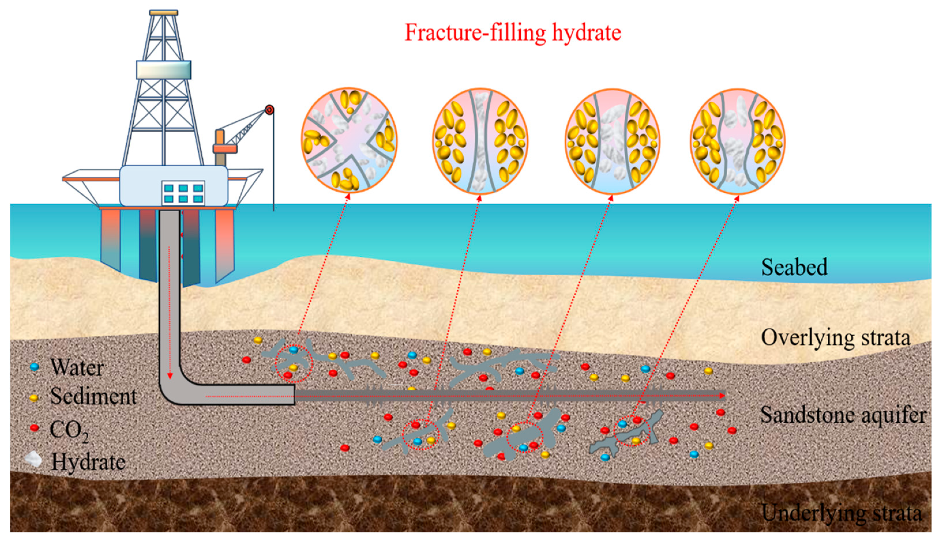
Figure 1. Mechanisms of CO2 hydrate filling in different sandstone fractures in seafloor.
Applsci 15 09440 g001
Figure 2. Schematic diagram of the high-pressure visualization system.
Applsci 15 09440 g002
Figure 3. Experimental flow chart.
Applsci 15 09440 g003
Figure 4. Temperature and pressure path.
Applsci 15 09440 g004
Figure 5. Under different fracture widths: (a) hydrate induction time; (b) total duration of hydrate growth process.
Applsci 15 09440 g005
Figure 6. Observation images of hydrate growth under different fracture widths.
Applsci 15 09440 g006
Figure 7. CO2 gas consumption curves during hydrate formation process under different fracture widths.
Applsci 15 09440 g007
Figure 8. Micrographs of hydrate morphology within fractures.
Applsci 15 09440 g008
Figure 9. Comparison of CO2 Consumption Gas Curves During Hydrate Formation in I-type and X-type Fractures with Varying Crack Widths.
Applsci 15 09440 g009
Figure 10. Observational Images of Hydrate Growth in I-type and X-type Fractures with Different Crack Widths.
Applsci 15 09440 g010
Figure 11. Hydrate formation duration: (a) I-type fracture; (b) X-type fracture.
Applsci 15 09440 g011
Figure 12. CO2 consumption curves during hydrate formation in fractures of different types: (a) CO2 consumption curves for I-type fractures; (b) CO2 consumption curves for X-type fractures.
Applsci 15 09440 g012
Figure 13. Morphology of CO2 hydrate in rough fractures.
Applsci 15 09440 g013
Figure 14. Observation images of hydrate dissociation under different fracture widths.
Applsci 15 09440 g014
Figure 15. Temperature variations during hydrate dissociation under 2.9 MPa pressures.
Applsci 15 09440 g015
Figure 16. Nucleation area distribution of CO2 hydrate formation in rough fractures.
Applsci 15 09440 g016
Figure 17. CO2 consumption curves during hydrate formation in fractures of different widths.
Applsci 15 09440 g017
Table 1. Experimental parameters and conditions.
NumberPressureFracture TypeFracture Width [mm]Roughness [mm]Note
12.9 MPaI3/6/10/3 groups
2X3/6/10/3 groups
3I102.5/3.52 groups
4X102.5/3.52 groups
Note: The surface roughness values of 2.5 mm and 3.5 mm correspond to the particle sizes of the glass sand used.
Table 2. Comparison of the duration of hydrate formation in different types of fractures at varying widths.
Pressure [MPa]Fracture TypeFracture Width [mm]Total Formation Duration [min]
2.9 MPaI381
682.17
10103.5
X357.83
671.33
1046.5
Disclaimer/Publisher’s Note: The statements, opinions and data contained in all publications are solely those of the individual author(s) and contributor(s) and not of MDPI and/or the editor(s). MDPI and/or the editor(s) disclaim responsibility for any injury to people or property resulting from any ideas, methods, instructions or products referred to in the content.