Article

An Improved Heave Compensation Algorithm for Strapdown INS in Marine Operations

by
Qianqian Gao
1,2,* and
Bixin Cai
1,2
1
School of Mechanical and Automotive Engineering, Anhui Polytechnic University, Wuhu 241000, China
2
Anhui Provincial Key Laboratory of Intelligent Car Wire-Controlled Chassis System, Wuhu 241000, China
*
Author to whom correspondence should be addressed.
Appl. Sci. 2025, 15(17), 9418; https://doi.org/10.3390/app15179418
Submission received: 25 July 2025 / Revised: 25 August 2025 / Accepted: 25 August 2025 / Published: 27 August 2025
(This article belongs to the Section Marine Science and Engineering)

Abstract

Heave compensation is crucial for the improvement of marine engineering. However, there remain two main drawbacks in existing methods. One drawback is that the output accuracy of heave information is insufficient. The other drawback is that the consideration of lever arm effect errors is inadequate. To address these challenges, a new heave compensation algorithm is proposed in this paper. Firstly, a vessel’s center of gravity acceleration model incorporating lever arm effect dynamics is established. Secondly, a modified high-pass filter is presented using complementary techniques. A comparative error analysis demonstrates its superiority over traditional digital filters in real-time performance. Thirdly, the algorithm independently updates solutions of the heave of the vessel’s center of gravity and the heave caused by the lever arm vector and the vessel’s attitude to avoid oscillating temporarily. Simulation results verified the better heave measurement accuracy of the proposed algorithm. This algorithm is pivotal to marine engineering.

1. Introduction

In marine navigation systems, vessels inevitably experience vertical-axis heave movements due to environmental disturbances such as wind and waves. Real-time and effective heave measurement proves critical for numerous maritime operations. It supports critical tasks like the launch of ship-borne weapons, aircraft take-off and landing, drilling platform heave compensation devices, and pipe-laying vessel stable structure [1,2,3]. With accurate heave information, the driving safety and reliability in marine navigation will be greatly improved. It is of great significance for the development of ocean engineering and modern navigation technology. Heave measurement primarily relies on the Inertial Navigation System (INS), which contains three accelerometers and three gyroscopes [4,5,6]. Because sensor bias and high-frequency noise still exist, the heave displacement calculated by integrating the heave acceleration twice would drift off rapidly. For that reason, many researchers devote themselves to studying high-precision heave measurement methods.
Basically, there are two main research areas for heave measurement. The Kalman filtering technique has the shortcoming of estimating the ship motion dependents on the external reference information. Triantafyllou, Reis, and Fossen employed a discrete-time Kalman filter to solve the problem of heave compensation in underwater applications [7,8,9]. The generalized Kalman filter (GKF) and extended Kalman filter (EKF) were used to address the high-dimensional nonlinear challenges in the ship heave motion model, respectively [10,11]. The cubature Kalman filter (CKF) and self-adaptive robust volumetric Kalman filter (SARCKF) were other solutions for such nonlinear systems [12,13]. Different from Kalman filtering techniques, digital filtering technology just employs the information of INS, and the algorithm structure of it is simpler than theirs. The digital filtering for heave estimation was proposed by Godhaven and implemented in Seatex MRU [14]. The high-pass filter introduces a positive phase to decrease the real-time performance of heave information. Ning et al. added a low-pass filter to avoid phase correction [15]. Hu et al. performed real-time zero-phase filtering to improve the accuracy of heave measurement [16]. Yan et al. proposed a new zero-phase-delay high-pass filter, which was converted by a low-pass filter [17]. Ben et al. proposed an adaptive band-pass filter based on strapdown INS to obtain heave information [18]. Wei et al. introduced a low-pass filter with parameters that can be adjusted in real time with the dominant frequency of the ocean wave to solve the phase lead error introduced by characteristics of the digital high-pass filter [19]. Lu et al. designed an adaptive digital high-pass filter [20]. The optimal cutoff frequency for the adaptive filter was determined by an analysis of filtering and sensor errors.
Digital filtering technology has become the most popular method for heave measurement. However, there remain two main drawbacks in existing methods. One drawback is that the output accuracy of heave information is insufficient. The other drawback is that only the lever arm vector from the INS to the MP is considered, and not the lever arm vector from the INS to the vessel’s center of gravity (CG). In practice, it is often not possible to mount the INS at precisely the CG. During vessel transient movement, roll and pitch change, and the measured acceleration of the INS is different from that of the CG. There exists an acceleration error between the acceleration of INS and CG: centripetal and linear acceleration. If the acceleration error is filtered through heave high-pass filters, it will induce a filter impulse response and lead to estimated heave temporary oscillations.
Aiming at the mentioned problems, a new heave calculation algorithm is proposed in this paper. Firstly, a vessel’s center of gravity acceleration model incorporating lever arm effect dynamics is established. The acceleration error, caused by the lever arm vector from the INS to the vessel’s CG and attitude, is derived in detail. The acceleration of the vessel’s CG is obtained from the measured acceleration of the INS and the acceleration error. Secondly, a modified high-pass filter is presented using complementary techniques. A comparative error analysis demonstrates its superiority over traditional digital filters in real-time performance. The heave of the vessel’s CG is calculated by the acceleration of the vessel’s CG, employing the proposed modified high-pass filter. Thirdly, the algorithm independently updates solutions of the heave of the vessel’s center of gravity and the heave caused by the lever arm vector and the vessel’s attitude to avoid temporary oscillations. Heave, which is caused by the lever arm vector from the vessel’s CG to the monitoring point and attitude, is calculated separately to avoid temporary oscillations. Accurate heave is obtained by the heave of the vessel’s CG, which is compensated by the heave that is caused by the lever arm vector and attitude.
The subsequent sections address: Section 2 presents the heave definition and conventional heave measurement methods. In Section 3, a proposed heave measurement method is described. Section 4 details simulation results and discussion. Finally, the article ends with a conclusion in Section 5.

2. Conventional Heave Measurement Methods

Conventional heave measurement methods are developed under the assumption that the INS is mounted at the vessel’s center of gravity. In other words, the fixed point of INS and the vessel’s center of gravity coincide. Generally, the fixed point of INS does not overlap with the monitoring point. Because the lever arm effect exists, which is caused by the ship’s roll and pitch, the heave motion of the fixed point of INS and the monitoring point is also different. For expressing and using conveniently in this study, let the primary lever arm denote the lever arm from point F to M. And the center of gravity lever arm denotes the lever arm from point F to CG.
The INS detects only a change in the vertical displacement for a certain period of time where it is fixed. Relative to the local geographic frame, due to the influence of the ship’s attitude and the primary lever arm, the heave of point M can be divided into two parts: translational heave H e a v e C G and induced heave H e a v e F _ M , which is
H e a v e M = H e a v e C G + H e a v e F _ M
where H e a v e C G corresponds to vertical movement due to waves, H e a v e F _ M due to the lever arm between F and M and vessel attitude (roll and pitch).
One can see the simplified 2D schematic of heave composition in Figure 1.
In Figure 1, CG denotes the center of gravity of the vessel. F is the fixed point of INS. M is the monitoring point. O X G Y G Z G is the geographic frame. This frame has its origin at the current geographic location and is fixed to the Earth’s surface. The frame is chosen with the following successive axes directions: X G geographic north, Y G geographic east, and Z G up. O X B Y B Z B is the body frame. This frame is fixed to the vehicle or ship with its origin in the ship’s center of gravity. The definition of the axes directions is as follows: X B the bow direction of a ship, Y B the starboard direction of a ship, and Z B the down in the direction of gravity. ϕ is roll angle. A rotation about Y B is defined as positive when the starboard side of the ship moves down.

2.1. Translational Heave

The acceleration signal a F G of point F contains not only the measurement acceleration a F B of point F but also several error sources. In the following, a F G can be described by the acceleration model [18]
a F G = C B G a F B + b + w a
where C B G is the transform matrix from B frame to G frame, and b and w a are the bias and high-frequency noise, respectively. a F G is represented by components a F G = a F x G a F y G a F z G T . Because sensor bias and high-frequency noise exist, the estimated heave calculated by integrating the measured z-axis acceleration a F z G twice would drift off rapidly. Therefore, a heave filter is usually applied to the measured z-axis acceleration a F z G to reduce the impact of sensor bias and high-frequency noise.
A heave filter is composed of the double integration and a high-pass filter. The double integration is used to remove the high-frequency noise and obtain heave information via acceleration a F z G . The high-pass filter is employed to remove the gravitational constant and the slowly time-varying bias.
A heave filter, which includes double integration H i s and a high-pass filter H h p s , is given by [19]
H s = H i 2 s H h p s
where integration H i ( s ) meets the requests
H i ( s ) = 1 s
and the high-pass filter as
H h p ( s ) = s 4 s 2 + 2 ζ ω c s + ω c 2 2
where s is the Laplace variable, ξ is the damping coefficient, ξ is normally taken 2 / 2 , and ω c is the cutoff frequency of the high-pass filter.
The high-pass filter changes the amplitude and phase characteristics of the desired signals. Therefore, the choice of the cutoff frequency ω c directly affects the results of the heave measurement. Leaving the phase shift out of account, the amplitude error induced by the high-pass filter is
Δ 1 = H e a v e C G H ^ e a v e C G H e a v e C G
where H ^ e a v e C G is the calculated heave displacement, and H e a v e C G is the true heave displacement.
Since the true heave displacement is the double integration of the heave acceleration, we have
H e a v e C G s = H i 2 ( s ) a F z G s
The calculated heave displacement is the double integration and high-pass filtering of the heave acceleration
H ^ e a v e C G ( s ) = H i 2 s H h p ( s ) a F z G ( s )
Compared (7) with (8), we get
H ^ e a v e C G ( s ) = H h p ( s ) H e a v e C G ( s )
Using (9), the amplitude response error is expressed by
Δ 1 = 1 H h p s  
With the aid of s = j ω and (4), (10) is rewritten as
Δ 1 = 1 1 ω c / ω 4 + 1 ω c ω 4   for   ω ω c
where ω is the dominant frequency of wave motion, obtained by the fast Fourier transform (FFT) of the measured z-axis acceleration.
The applied cutoff frequency is determined by satisfying performance specifications. The performance specification of 2% peak-to-peak error is reached when
ω c ( 0.02 ) 1 4 ω 0.37 ω
If the dominant frequency of wave motion is 0.1 Hz, it is necessary that the cutoff frequency ω c 0.037   Hz . In this paper, the equation ω c = 0.03   Hz is used to obtain the cutoff frequency.
The transfer function can only be used in a continuous system, and the measured signals from INS and the designed compensation system are discrete. Thus, the bilinear transformation is adopted to perform the conversion between an analog filter H s and a digital filter H z , of which the basic relationship is [20]
s = 2 T 1 z 1 1 + z 1
where T is the update period.
Translational heave is calculated by
H e a v e C G = H z a F z G
In practice, there is a need for a real-time estimate of heave to compensate for the wave motion. The real-time heave error for filter (4) is given by
Δ 2 = H e a v e C O G H ^ e a v e C O G H e a v e C O G
Using (7), the real-time heave error is expressed by
Δ 2 = 1 H h p s  
With the aid of s = j ω and (4), (16) is rewritten by
Δ 2 = ω c 8 + 8 ω 6 ω c 2 ω 4 + ω c 4 2 2 ω c ω   for   ω ω c
In comparison of (11) and (17), the real-time heave error Δ 2 is much greater than the amplitude response error Δ 1 . Most of Δ 2 is due to the positive phase. This means that the measurement is sometimes ahead of the actual wave.
The phase error is large and would significantly influence the accuracy of heave estimation. In order to improve the accuracy of heave measurement, many researchers share the same spirit of trying to find the real-time phase compensation methods.
For example, Ning et al. introduced a low-pass filter that cascaded after the heave filter to avoid phase correction [15].
H e a v e C G = H i 2 z H h p z H l p z a F z G
where
H l p s = ω l 4 s 2 + 2 ξ ω l s + ω l 2 2
The phase response of H h p s and H l p s with s = j ω are written as
H h p s = arctan 2 2 ω c ω ω 2 ω c 2 ω 4 + ω c 4 4 ω c 2 ω 2 H l p s = arctan 2 2 ω l ω ω 2 ω c 2 ω 4 + ω l 4 4 ω l 2 ω 2
The low-pass cutoff frequency ω l is determined by
H h p s + H l p s = 0
Another attempt is by Hu et al., who employed an all-pass filter H a p s to balance the phase lead [16].
H e a v e C G = H i 2 z H h p z H a p z a F z G
where
H a p z = a + z 1 1 + a z 1
The phase response of the all-pass filter is
H a p s = ω 2 arctan a sin ( ω T ) 1 + a cos ( ω T )
The coefficient a is determined by
H h p s + H a p z = 0
However, the real-time performance of those phase compensation methods was not enough.

2.2. Induced Heave

H e a v e F _ M induced the heave of (1) due to the primary lever arms and vessel attitude (roll and pitch). It corresponds to the projection difference between the with and without pitch and roll of the primary lever arms r F _ M B = r F _ M x B r F _ M y B r F _ M z B on the vertical axis of the geographic frame [17].
H e a v e F _ M = r ^ F _ M z G r F _ M z G
where r ^ F _ M z G is the projection with pitch and roll of the primary lever arms on the vertical axis of the geographic frame. r F _ M z G is the projection without pitch and roll of the primary lever arms on the vertical axis of the geographic frame.
The relationship between r ^ F _ M z G and r F _ M B is:
r ^ F _ M x G r ^ F _ M y G r ^ F _ M z G = C B G r F _ M x B r F _ M y B r F _ M z B
where
C B G = cos ψ cos θ cos ψ sin θ sin ϕ sin ψ cos ϕ cos ψ sin θ cos ϕ + sin ψ sin ϕ sin ψ cos θ cos ψ cos ϕ + sin ψ sin θ sin ϕ cos ψ sin ϕ + sin ψ sin θ cos ϕ sin θ cos θ sin ϕ cos θ cos ϕ
The projection r ^ F _ M z G is
r ^ F _ M z G = r F _ M x B sin θ + r F _ M y B cos θ sin ϕ + r F _ M z B cos θ cos ϕ
The relationship between r F _ M z G and r F _ M B is:
r F _ M x G r F _ M y G r F _ M z G = C B G r F _ M x B r F _ M y B r F _ M z B
where
C B G = 1 0 0 0 1 0 0 0 1
The projection r F _ M z G is
r F _ M z G = r F _ M z B
Therefore, the induced heave H e a v e F _ M can be expressed as [13]
H e a v e F _ M = r F _ M x B sin θ + r F _ M y B cos θ sin ϕ + r F _ M z B cos θ cos ϕ 1
Finally, the heave information of M is calculated by (14) and (29)
H e a v e M = H e a v e C G + H e a v e F _ M
Generally speaking, it is often not possible to mount the INS at precisely the CG. There is the center of gravity lever arm. During turns, when roll and pitch change, the measured acceleration of the INS includes an acceleration error δ a . This acceleration error will act like an impulse response to the heave filter and make the estimate oscillate temporarily.
For example, the filter impulse response is obtained by the inverse Laplace transform of the heave filter
h ( t ) = L 1 ( H ( s ) )
Substituting (5) into (10) yields
h t = 1 ω c / 2 t · sin ω c / 2 t ω c / 2 exp ω c / 2 t
The heave error caused by the impulse response of the heave filter and heave acceleration error δ a is given by [14]
H ˜ e a v e t = δ a 1 ω c / 2 t · sin ω c / 2 t ω c / 2 exp ω c / 2 t
Based on the above analysis, the center of gravity lever arm effect should be taken into account.

3. Proposed Heave Measurement Methods

Based on the above analysis of conventional heave measurement methods, the output accuracy of heave information and the center of gravity lever arms effect should be taken into account. A novel heave measurement method is proposed in this section.
3.1. Acceleration Model That Considers the Lever Arm Effect

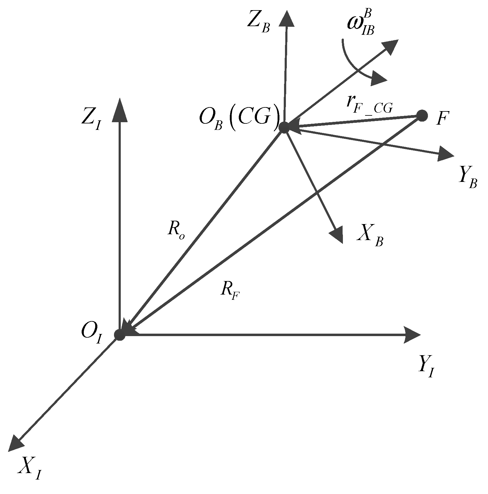
In order to elaborate on the acceleration model, which considers the lever arm effect, the inertial frame O I X I Y I Z I and body frame O B X B Y B Z B are introduced, as shown in Figure 2.
In Figure 2, O I is the origin of inertial space, and O B is the center of gravity of the vessel. F is the fixed point of INS. R O is a position vector from O B to O I , and R F is a position vector from F to O I . r F _ C G is a position vector from F to C G . ω I B B is the angular rate of the body frame with respect to the inertial space.
It is not difficult to find that the vector relationship between R O , R F and r F _ C G is
R F = R O + r F _ C G
Differentiating over the time interval of interest
( d R F d t ) I = ( d R O d t ) I + ( d r F _ C G d t ) I
According to the relationship between the absolute derivative and the relative derivative of a vector
( d R F d t ) I = ( d R O d t ) B + ω I B B × r F _ C G
Because r F _ C G can be expressed as a constant in the body frame, so
( d r F _ C G d t ) B = 0
Hence, (36) can be written as
( d r F _ C G d t ) I = ω I B B × r F _ C G
Substituting (38) into (35) yields
( d R F d t ) I = ( d R O d t ) I + ω I B B × r F _ C G
where ( · ) I and ( · ) B denote differentiation with respect to inertial space and body frame, respectively. ( d R O d t ) I is the acceleration of O B with respect to the inertial space, and ( d R F d t ) I is the acceleration of F point with respect to the inertial space. ω I B B is the angular rate of the body frame with respect to the inertial space.
Differentiating (39) over the time interval of interest
( d 2 R F d t 2 ) I = ( d 2 R O d t 2 ) I + d d t ( ω I B B × r F _ C G ) I
According to the relationship between the absolute derivative and the relative derivative of a vector
d d t ( ω I B B × r F _ C G ) I = ω ˙ I B B × r F _ C G + ω I B B × ( ω I B B × r F _ C G )
The acceleration of F point with respect to the inertial space is obtained by substituting (41) into (40)
( d 2 R F d t 2 ) I = ( d 2 R O d t 2 ) I + ω ˙ I B B × r F _ C G + ω I B B × ( ω I B B × r F _ C G )
In the ideal case, the fixed point of the INS is located at the CG of the vessel. The specific force that is sensed by the accelerometer is ( d 2 R O d t 2 ) I . When the fixed point of the INS is not located at the CG of the vessel, r F _ C G is not zero, and the specific force that is sensed by the accelerometer is ( d 2 R F d t 2 ) I . Therefore, the lever arm effect error δ f is expressed by
δ f = ( d 2 R F d t 2 ) I ( d 2 R O d t 2 ) I
According to (42), δ f is expressed by
δ f = ω ˙ I B B × r F _ C G + ω I B B × ( ω I B B × r F _ C G )
The acceleration error model, which considers the lever arm effect, is
a ˜ F G = a F G δ f
With the aid of (2) and (43), (45) is rewritten as
a ˜ F G = C B G a F B + b + w a ω ˙ I B B × r F _ C G ω I B B × ( ω I B B × r F _ C G )

3.2. Real-Time Heave Measurement Method

To overcome the significant phase lead error that traditional high-pass digital filters exhibit, a modified high-pass filter is proposed. And a comparative error analysis demonstrates its superiority over traditional digital filters in real-time performance.

3.2.1. Design Method of the Modified High-Pass Filter

The design of the modified high-pass filter, employing the complementarity between the low-pass filter and high-pass filter, is introduced as follows:
As for the input signal x s , if the input signal is processed by a low-pass filter H l p s , the output component y l s is expressed by [21]
y l s = H l p s x s
According to the filtering principle of the low-pass filter, the output signal y l s is a low-frequency component. Obviously, the signal x s y l s , which is filtered out by the low-pass filter H l p s , is a high-frequency component consequentially.
If one needs to preserve the high-frequency component of the input signal x s , one could define the high-frequency component as
y h s = x s y l s
Substituting (47) into (48) yields
y h s = x s H l p s x s
Equation (49) may be recast in the form
y h s = 1 H l p s x s
As for the input signal x s , if the input signal is processed by a high-pass filter H h p s , the output component y h s is expressed by
y h s = H h p s x s
According to (50) and (51), one obtains
H h p s = 1 H l p s
Equation (52) is the modified high-pass filter, which is realized indirectly by designing the traditional low-pass filter.
For example, the transfer function of the traditional low-pass filter is
H l p ( s ) = ω c 2 s 2 + 2 ζ ω c s + ω c 2
Substituting (53) into (52) yields the transfer function of the modified high-pass filter
H m h p s = s 2 + 2 ζ ω c s s 2 + 2 ζ ω c s + ω c 2
How to choose the cutoff frequency is similar to the traditional method with 2% peak-to-peak error.

3.2.2. Verifying the Superiority of the Modified High-Pass Filter

In order to verify that the modified high-pass filter could effectively solve the problem of signal delay, Δ 2 and Δ 1 of the modified high-pass filter are derived.
Firstly, we derive the real-time heave error of the modified high-pass filter, and compare it with that of the traditional high-pass digital filter.
The real-time heave error for the modified high-pass filter, which is shown by (8), is given by
Δ 2 = 1 H m h p 2 s  
With the aid of s = j ω
1 H m h p 2 j ω = ω c 4 2 ω c 2 ω 2 + 4 ζ ω c 3 ω j ω 4 + ω c 4 4 ζ ω c 2 ω 2 2 ω c 2 ω 2 4 ζ ω c ω 3 j + 4 ζ ω c 3 ω j
The real-time heave error is rewritten as
Δ 2 = ω c 4 2 ω c 2 ω 2 2 16 ζ 2 ω c 6 ω 2 ω 4 + ω c 4 4 ζ ω c 2 ω 2 2 ω c 2 ω 2 2 16 ζ 2 ω c 3 ω ω c ω 3 2
When ω ω c , (57) is expressed by
Δ 2 ω c ω 4  
In comparison of (17) and (58), the real-time heave error Δ 2 of the modified high-pass filter is much smaller than that of the traditional high-pass digital filter.
The amplitude response error of the modified high-pass filter is expressed by
Δ 1 = 1 H m h p 2 s  
With the aid of s = j ω
H m h p 2 j ω = ω c 4 4 ζ 2 ω c 2 ω 2 4 ζ ω c ω 3 j ω 4 + ω c 4 4 ζ ω c 2 ω 2 2 ω c 2 ω 2 4 ζ ω c ω 3 j + 4 ζ ω c 3 ω j
The magnitude of H m h p 2 j ω is
H m h p 2 j ω = ω c 4 4 ζ ω c 2 ω 2 2 + 16 ζ 2 ω c 2 ω 6 ω 4 + ω c 4 4 ζ ω c 2 ω 2 2 ω c 2 ω 2 2 16 ζ 2 ω c 3 ω ω c ω 3 2
The amplitude response error is rewritten as
Δ 1 = ω 4 + ω c 4 4 ζ ω c 2 ω 2 2 ω c 2 ω 2 2 16 ζ 2 ω c 3 ω ω c ω 3 2 ω c 4 4 ζ ω c 2 ω 2 2 + 16 ζ 2 ω c 2 ω 6 ω 4 + ω c 4 4 ζ ω c 2 ω 2 2 ω c 2 ω 2 2 16 ζ 2 ω c 3 ω ω c ω 3 2
For ω ω c , (62) is rewritten by
Δ 1 ω c ω 4  
Compared with the real-time heave error Δ 2 , which is shown by (58), we find that Δ 2 is the same as Δ 1 of the modified high-pass filter when ω ω c . That means that the modified high-pass filter changes the phase characteristic of the desired signal slightly.

3.3. Compensation Package of the Lever Arm Effect

To avoid the effect of vessel transient movement on heave measurement, the lever arm effect error δ f should not be filtered by the filter. In other words, δ f should be compensated before it is filtered by the filter, i.e.,
a C G G = a ˜ F G + δ f
Translational heave is calculated by
H e a v e C G = H i 2 z H m h p 2 z a C G G
The induced heave H e a v e F _ C G caused by the center of gravity lever arms can be expressed as
H e a v e F _ C G = r F _ C G x B sin θ + r F _ C G y B cos θ sin ϕ + r F _ C G z B ( cos θ cos ϕ 1 )
Finally, the heave information of M using the proposed method is calculated by (28), (65), and (66)
H e a v e M = H e a v e C G H e a v e F _ C G + H e a v e F _ M

4. Results and Discussion

To justify the proposed heave measurement algorithm, a variety of simulations are performed in this section. The software environment used for modeling is C++6.0. Parameters of the computer on which the modeling is a Windows 10 system 64 byte, CPU Intel(R) Core(TM) i7-7700HQ, RAM 8.00 GB (Intel, Santa Clara, CA, USA).

4.1. Simulation for Real-Time Phase Compensation

A sinusoidal motion signal A sin ω t is regarded as the true value of heave, where A and ω denote the amplitude and peak frequency [14]. Simulation conditions and configurations of sensors are listed in Table 1 and Table 2. For each of the above cases, the same configurations of sensors are used. The total simulation time is 1 h.
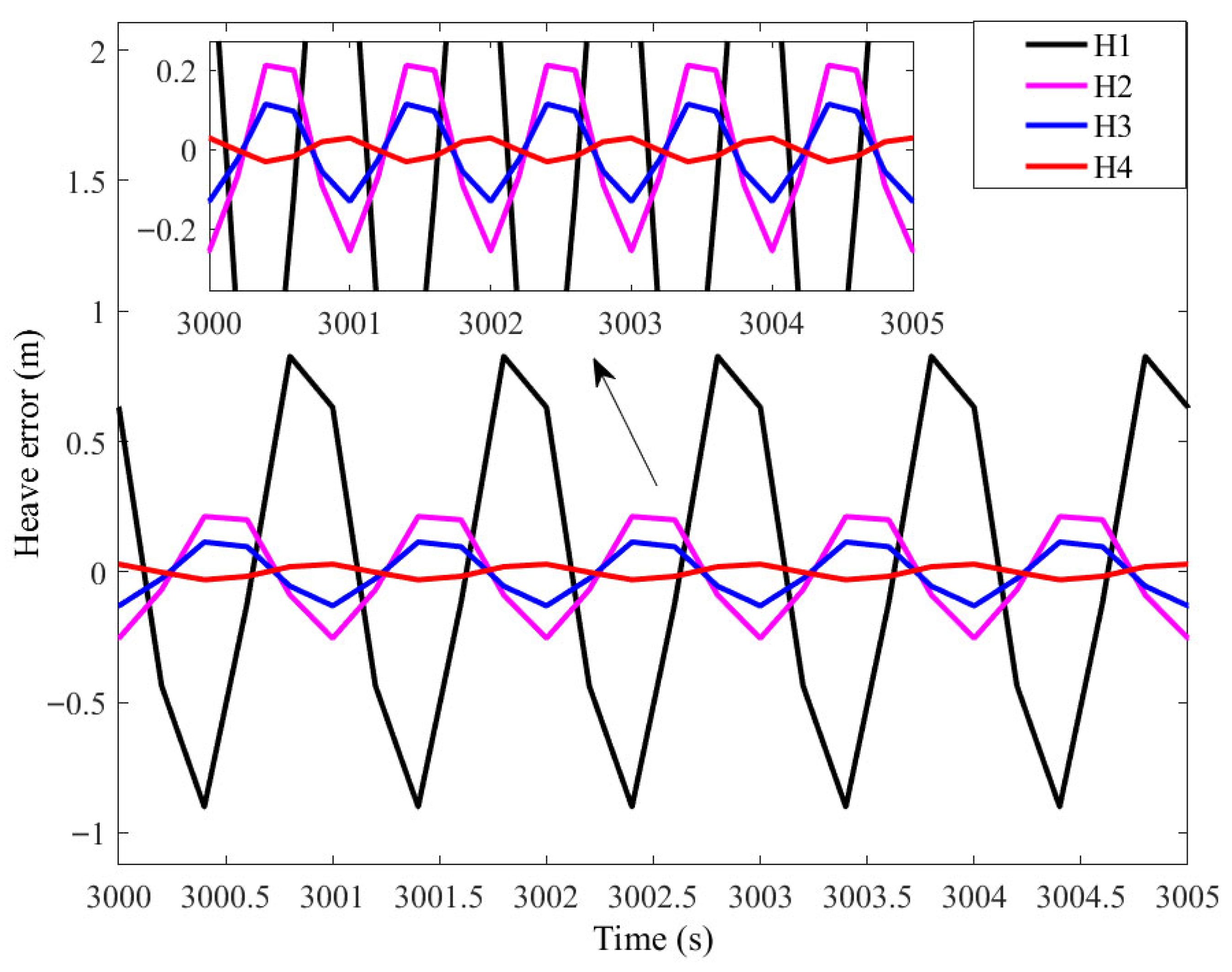
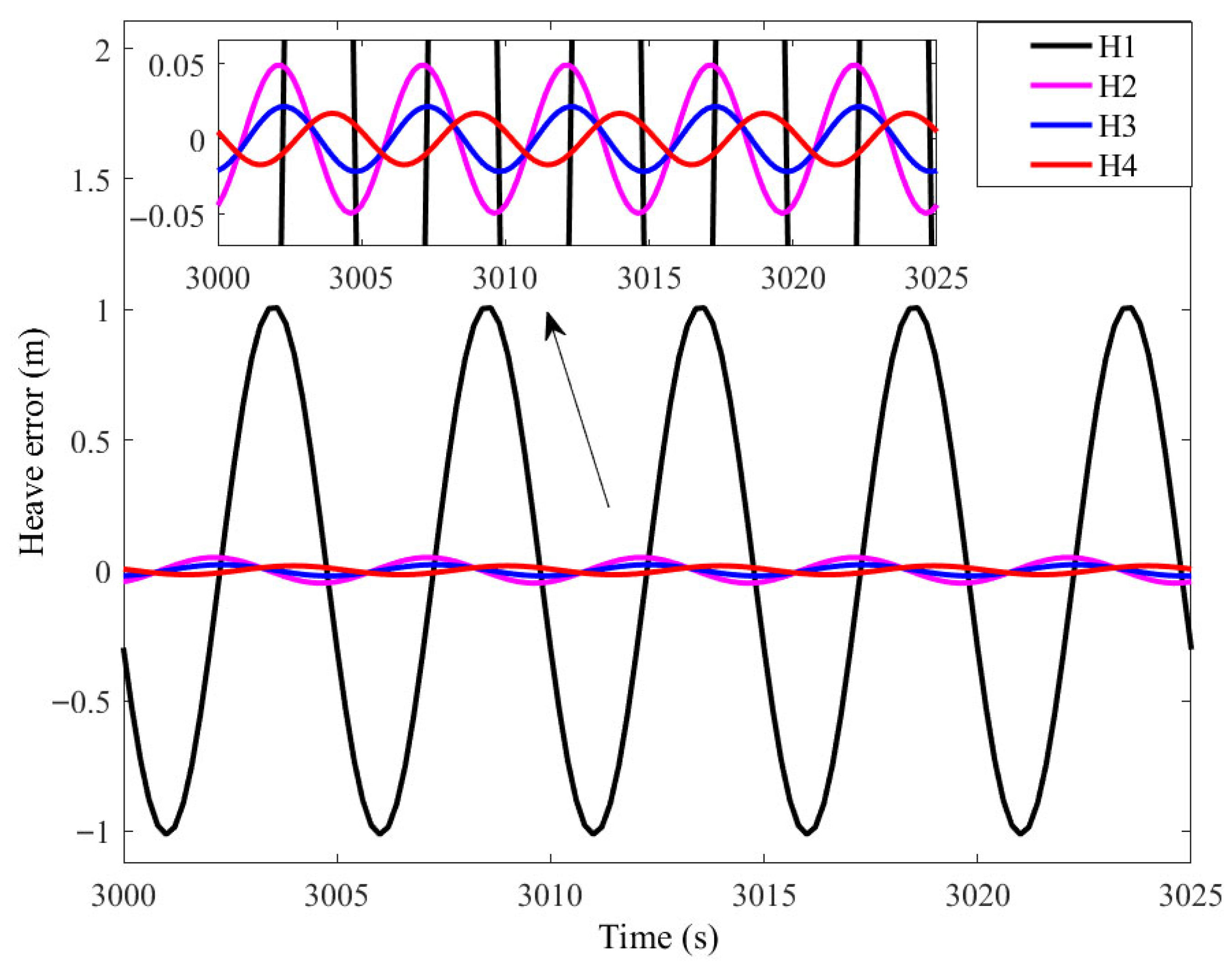
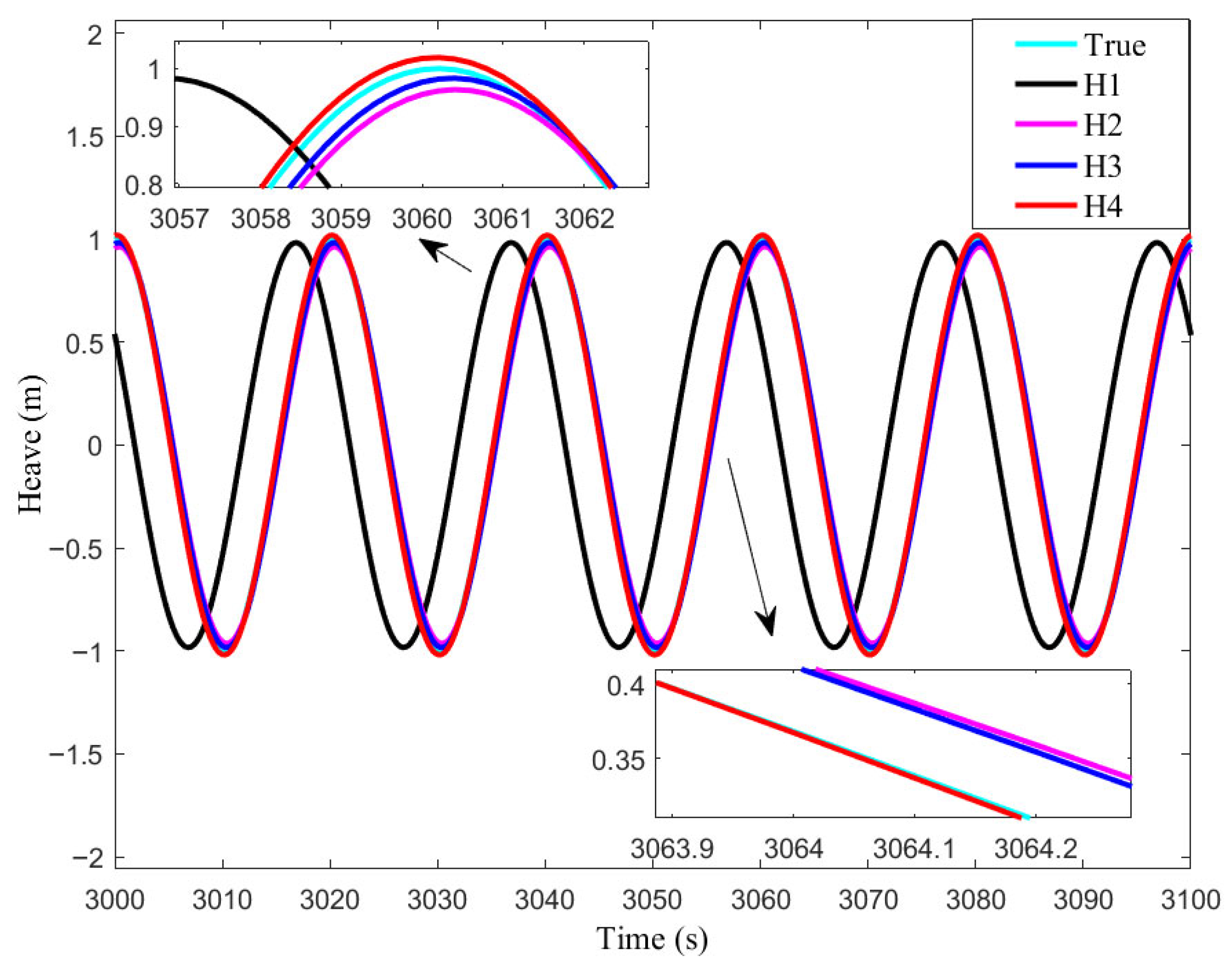
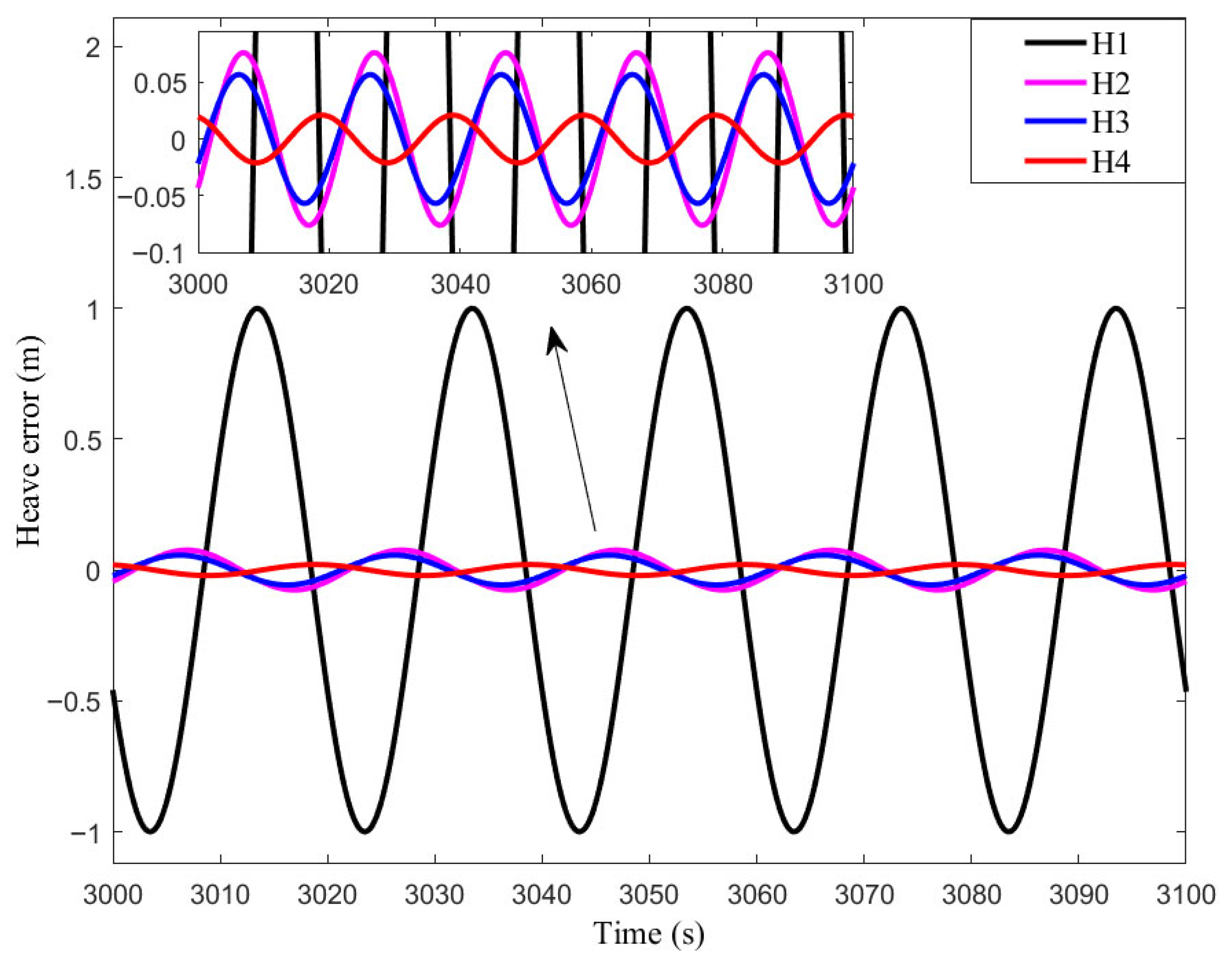
The simulation result for each case is illustrated in Figure 3, Figure 4, Figure 5, Figure 6, Figure 7, Figure 8, Figure 9, Figure 10, Figure 11 and Figure 12, respectively. Heave errors of each case are illustrated in Table 3.
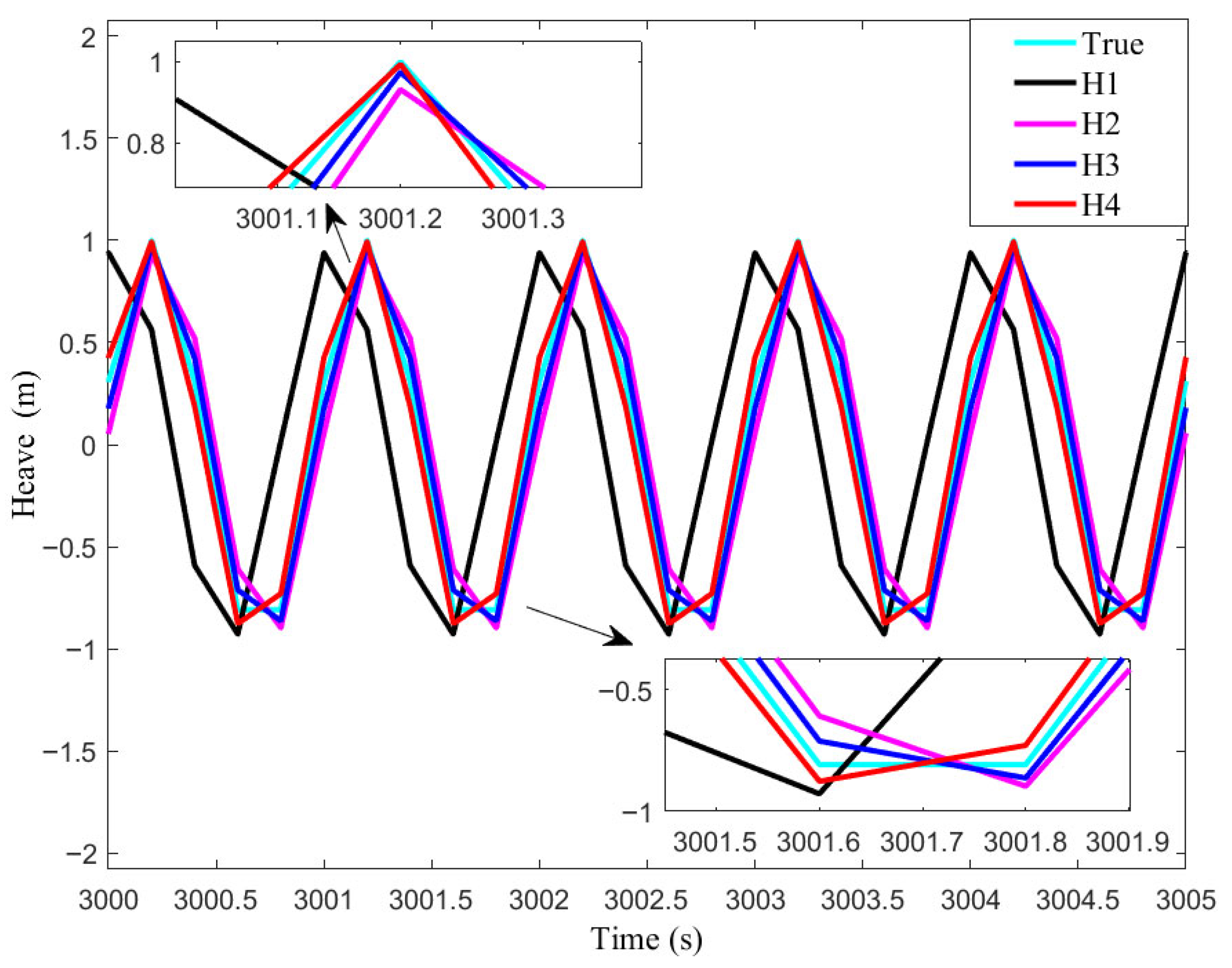
For clarity, in Figure 3, Figure 4, Figure 5, Figure 6, Figure 7, Figure 8, Figure 9, Figure 10, Figure 11 and Figure 12, True denotes the true value of H e a v e C G . H1, which denotes H e a v e C G gained through a double integrator and filtering by a high-pass filter of the vertical acceleration after removing the gravitational constant, is regarded by (14). H2, which denotes H e a v e C G gained through double integration and filtering by high-pass and low-pass filters of the vertical acceleration after removing the gravitational constant, is described by (18). H3, which denotes H e a v e C G gained through a double integrator and filtering by high-pass and all-pass filters, is described by (21). H4, which denotes H e a v e C G gained through a double integrator and filtering by the proposed modified high-pass filter of the vertical acceleration after removing the gravitational constant, is defined by (65). The difference between the calculated heave and the true value of heave is regarded as the heave error.
As shown in Figure 3, the heave values of H2–H4 are close to that of True. There is a time error between the heave value of H1 and True. Figure 4 shows that the maximum heave errors of H2–H4 reached 0.2545 m, 0.1303 m, and 0.0294 m, respectively, while H1 is almost 0.9009 m.
As shown in Figure 5, the heave values of H2–H4 are close to that of True. There is a time error between the heave value of H1 and True. Figure 6 shows that the maximum heave errors of H2–H4 reached 0.0493 m, 0.0216 m, and 0.0168 m, respectively, while H1 is almost 1.0134 m.
As shown in Figure 7, the heave values of H2–H4 are close to that of True. There is a time error between the heave value of H1 and True. Figure 8 shows that the maximum heave errors of H2–H4 reached 0.0374 m, 0.0195 m, and 0.0137 m, respectively, while H1 is almost 1.0242 m.
As shown in Figure 9, the heave values of H2–H4 are close to that of True. There is a time error between the heave value of H1 and True. Figure 10 shows that the maximum heave errors of H2–H4 reached 0.0364 m, 0.0199 m, and 0.0142 m, respectively, while H1 is almost 1.0273 m.
As shown in Figure 11, the heave values of H2–H4 are close to that of True. There is a time error between the heave value of H1 and True. Figure 12 shows that the maximum heave errors of H2–H4 reached 0.0761 m, 0.0567 m, and 0.0210 m, respectively, while H1 is almost 0.9994 m.
As shown in Table 3, in the five cases, the heave error of H1 exhibited the highest error due to the absence of phase compensation. This was followed by H2 due to the low-pass filter inducing heave amplitude attenuation. The heave error of H3 ranks third. The heave error of H4 is listed last, and the error of H4 was kept within 5 cm. This corresponds to the proposed filter changing the phase characteristic of the desired signal slightly, as seen in Section 3.2.2.

4.2. Simulation for Lever Arm Compensation

In this section, the lever arms and the attitude information are introduced to show the effect of the lever arms and the attitude information. In addition, the amplitude and peak frequency of the true value of heave at CG are A = 1   m and ω = 0.2 π   rad / s . The lever arm heave depends on the lever arms and attitude (roll and pitch). Simulation conditions are listed in Table 4. For each of the above conditions, the same configurations of sensors, which are listed in Table 2, and the proposed real-time phase compensation method are carried out. The total simulation time is 1 h.
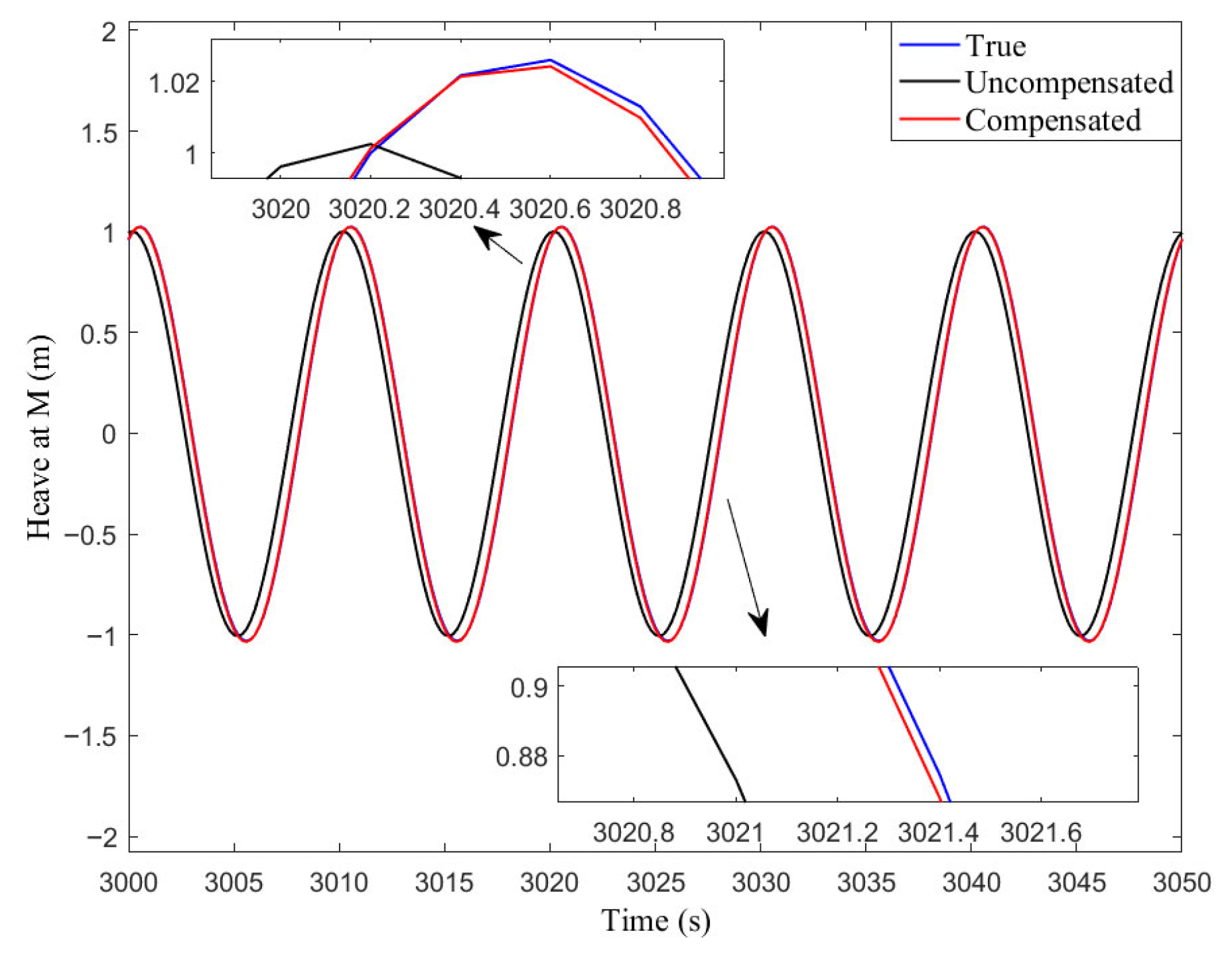
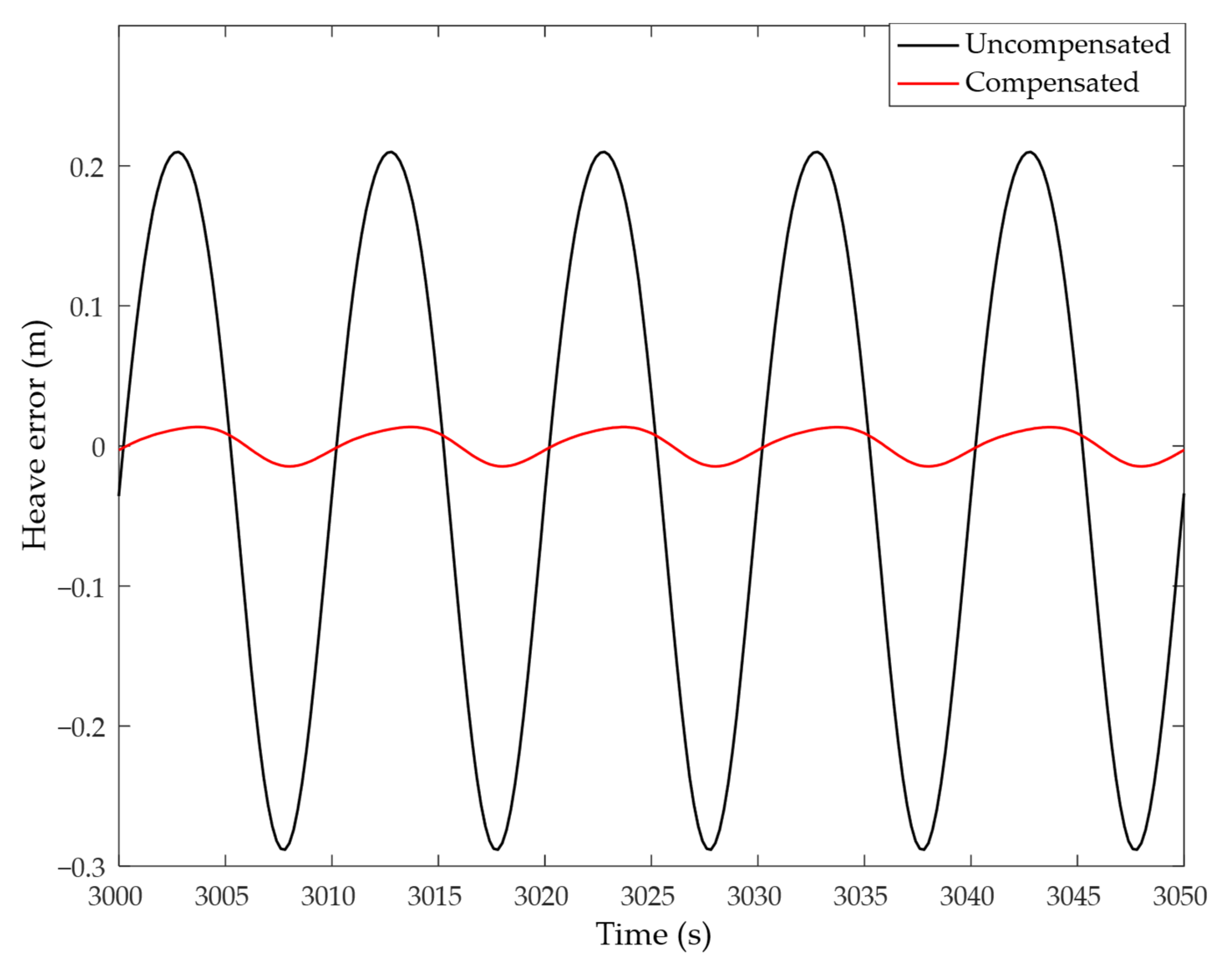
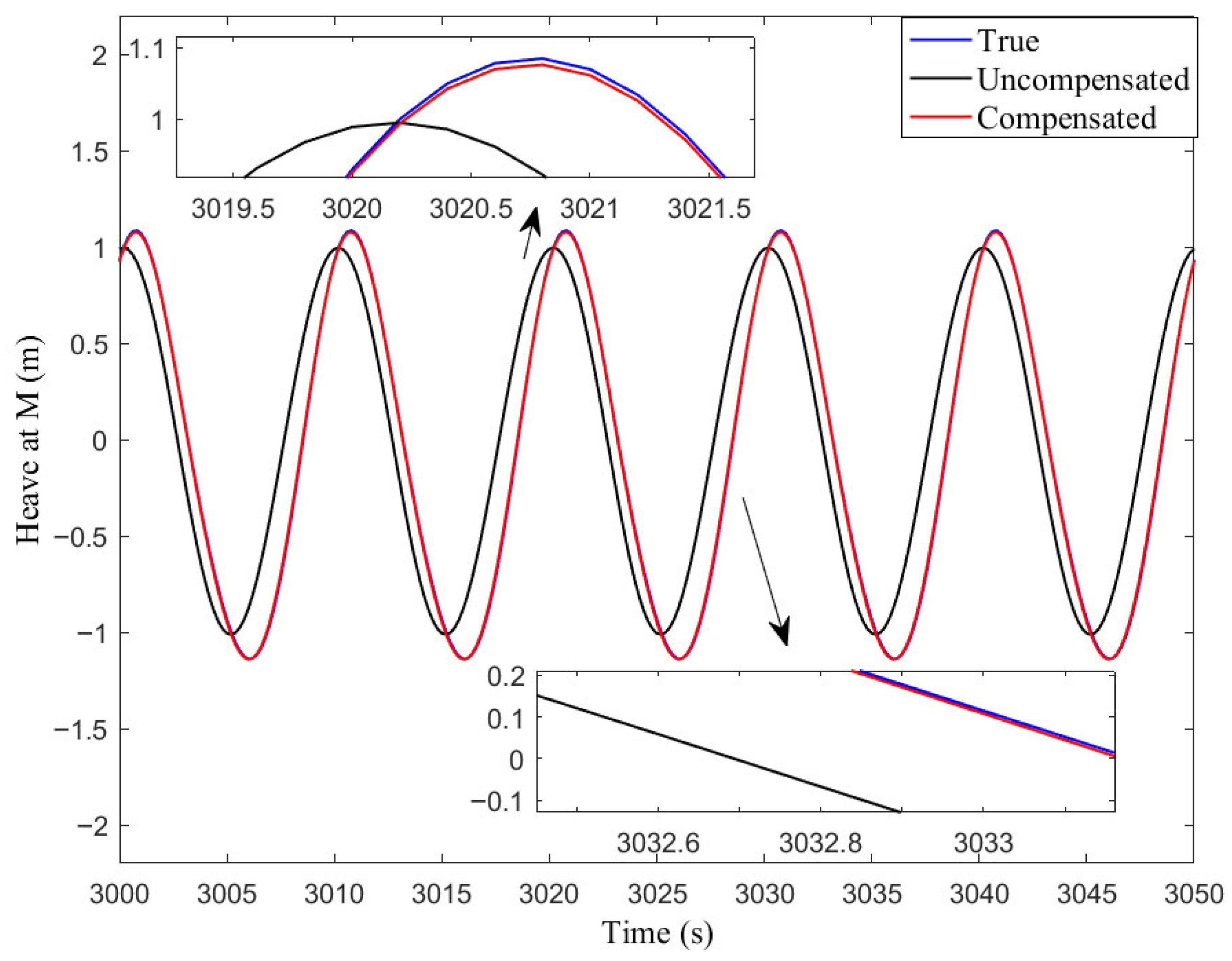
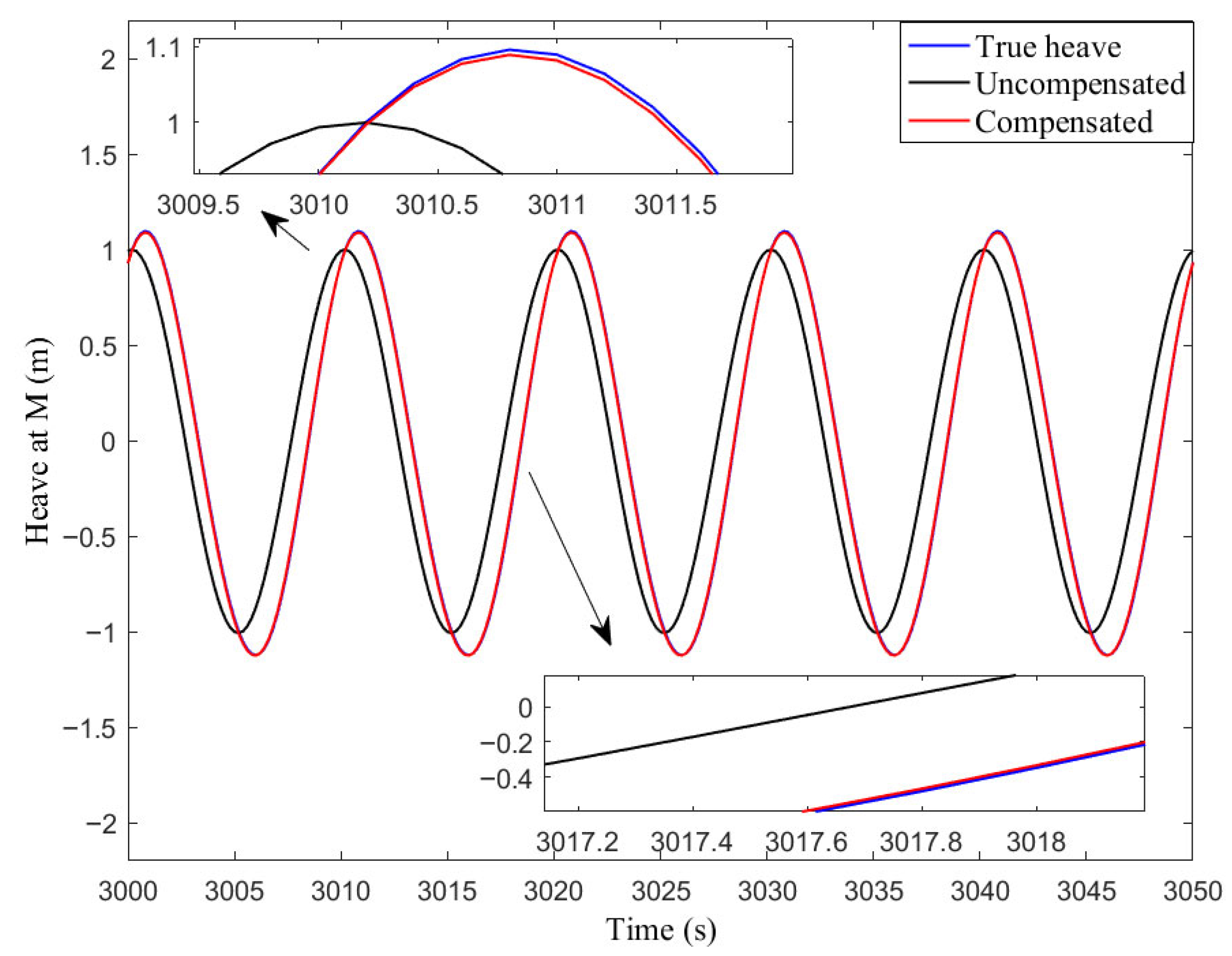
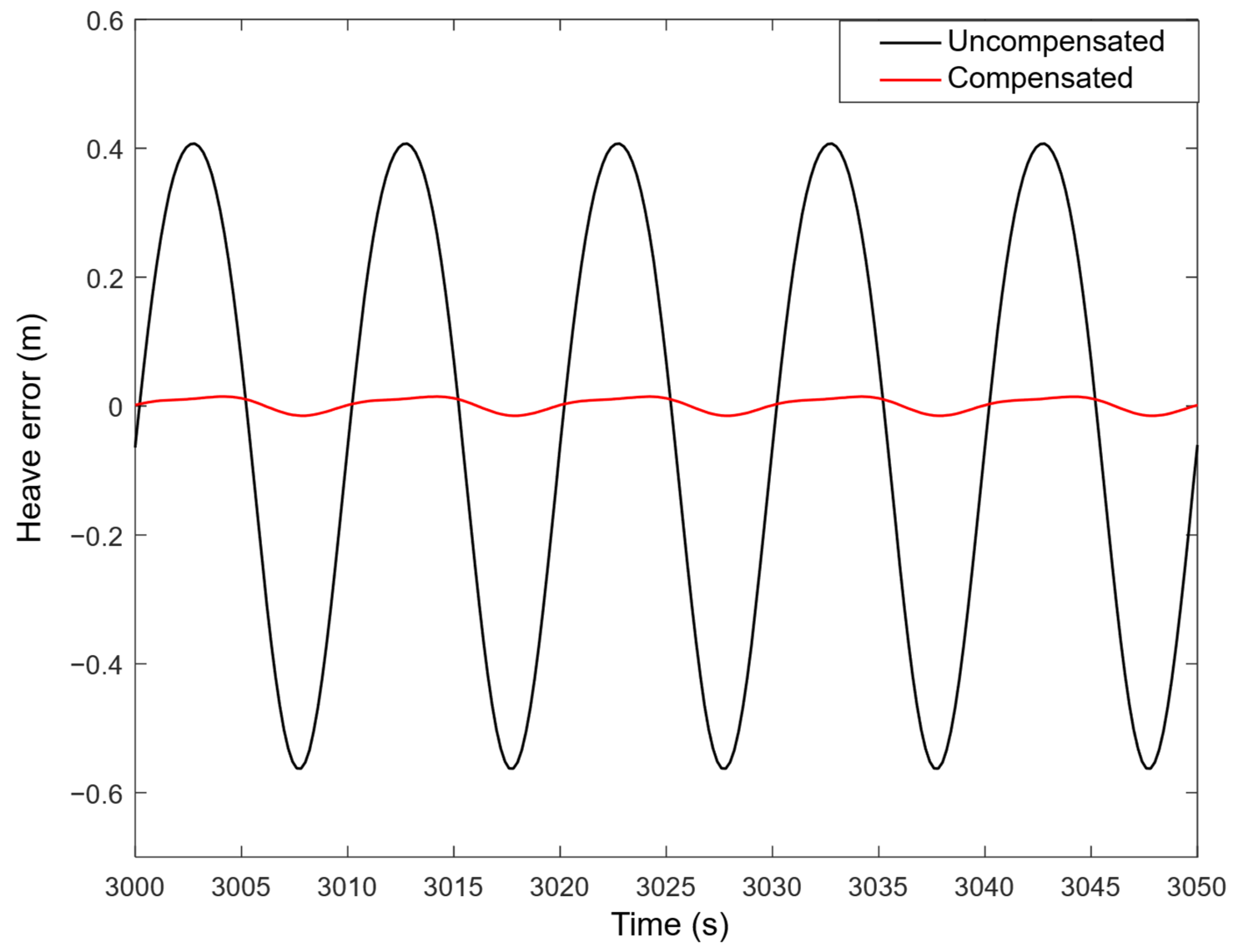
The conventional method was described by (30), which represents heave at M that is not lever arm compensation. The proposed method is described by (67), which denotes heave at M that is compensated by induced heave H e a v e F _ C G , and lever arm effect error δ f is compensated before it is filtered by the filter. The simulation result for each condition is illustrated in Figure 13, Figure 14, Figure 15, Figure 16, Figure 17 and Figure 18, respectively.
It is easy to find from Table 5 and Figure 13, Figure 14, Figure 15, Figure 16, Figure 17 and Figure 18 that when the ship’s roll and pitch angles increased, the heave error of “Uncompensated” and “Compensated” changed from 0.2888 m and 0.0155 m to 0.6177 m and 0.0216 m, respectively. The heave error of “Uncompensated” and “Compensated” changed from 0.2888 m and 0.0155 m to 0.5633 m and 0.0166 m, respectively, when the lever arm information is enlarged. Among the three conditions, the error of condition 2 is the largest, the error of condition 3 is the second, and the error of condition 1 is the smallest. The heave error of “Uncompensated” of each condition has reached the decimeter level. The heave error of “Compensated” is small and kept within 5 cm in each condition. The reason why the heave error of “Uncompensated” is much larger than that of “Compensated” is that there was no compensation of lever arm effect in “Uncompensated”. The proposed algorithm demonstrates highly effective compensation for lever arm effects.
The comparative error analysis conclusively demonstrates that the proposed algorithm outperforms conventional methods in terms of precision. Concurrently, the computational complexity remains equally crucial for evaluating the algorithm’s real-time performance. An analysis of computational complexity (computational time and resource consumption) of different algorithms is as follows:
(1) A filter characterized by a difference equation requires storing historical input and output data, with storage capacity and actual resource consumption increasing linearly with the filter order. Furthermore, the output computation involves multiply-accumulate operations, and the number of such operations also scales linearly with the order [21]. Thus, computational time and resource consumption of the digital filter is in direct proportion to filter order. Regarding the computational complexity of H e a v e C G , one can obtain computational complexity results by comparing the filter order of different digital filters, as shown in Table 6.
Table 6 shows that the computational complexity of H2 is the largest, owing to high-pass and low-pass filters cascaded together. It is followed by the computational complexity of H3, owing to high-pass and all-pass filters cascaded together. H1 and H4 are the smallest, and they are equal.
(2) Regarding the computational complexity of H e a v e M , one finds that the computational complexity of “Compensated” is larger than “Uncompensated” by comparing Equations (30) and (67). This is due to the lever arm effect error δ f needing to be calculated and filtered by the filter, and the induced heave H e a v e F _ C G needing to be calculated and reduced by H e a v e M .
By the above analysis, the computational complexity of the proposed algorithm is larger than conventional methods.
The limitations and future improvements of this study:
This algorithm is designed for the general heave motion situation, in which the amplitude ranges from −50 m to 50 m and frequency is less than 25 s, respectively. This algorithm does not adapt to extreme dynamic sea conditions.
This algorithm is designed for modeling heave motion as a sinusoidal motion signal. In other words, only single amplitude and peak frequency. In practice, real seas have wider frequency bands, all with energy that contributes significantly to the total heave. How to ensure the superiority of the proposed algorithm in wider frequency bands will be our future research.
Due to limitations such as laboratory conditions, and the lack of appropriate experimental tools, it is impractical to conduct the related experiments at present. Looking ahead, the authors will place more emphasis on real-world experimental validation.
The Finite Element Method (FEM) is an essential numerical tool in marine engineering. Its integration with heave compensation algorithms enhances dynamic monitoring of marine structures. So, establishing this integration will be our future research. In addition, a full-fledged system for users will be developed in the future. The user interface should be presented, and for the possibility of its use in real time, the time required for all ship roll calculations should be considered, as it is important to obtain results quickly.

5. Conclusions

A new heave compensation algorithm is proposed in this paper. The acceleration error, caused by the lever arm vector from the INS to the vessel’s CG and attitude, is derived in detail. The acceleration of the vessel’s CG is obtained by the measured acceleration of the INS and the acceleration error. A modified high-pass filter is presented using complementary techniques. A comparative error analysis demonstrates its superiority over traditional digital filters in real-time performance. Heave of the vessel’s CG is calculated by the acceleration of the vessel’s CG employing the proposed modified high-pass filter. Heave, which is caused by the lever arm vector from the vessel’s CG to the monitoring point and the ship’s attitude, is calculated separately to avoid oscillating temporarily. Accurate heave is obtained by the heave of the vessel’s CG, which is compensated by the heave caused by the lever arm vector and attitude. Simulation results verified the better accuracy of the proposed heave algorithm.
Of course, this algorithm possesses some limitations and requires future improvements. This algorithm does not adapt to extreme dynamic sea conditions. How to ensure the superiority of the proposed algorithm in wider frequency bands will be our future research. This algorithm has not been validated by a real-world experiment. Real-world sea trials or comparing the algorithm’s performance against GNSS-derived heave data will be a future improvement. Considering the use of FEM in marine engineering, establishing its integration with heave compensation algorithms will be our future research. In addition, a full-fledged system for users will be developed in the future. Further research in this area significantly enhances the safety standards of marine operations. It also delivers indispensable technological support for ship navigation, resource exploitation, and defense systems.

Author Contributions

Conceptualization, Q.G. and B.C.; methodology, Q.G.; software, B.C.; validation, Q.G. and B.C.; formal analysis, B.C.; investigation, B.C.; resources, Q.G.; data curation, Q.G.; writing—original draft preparation, Q.G.; writing—review and editing, Q.G.; visualization, B.C.; supervision, B.C.; project administration, Q.G. and B.C.; funding acquisition, Q.G. All authors have read and agreed to the published version of the manuscript.

Funding

This research was funded by the Anhui Provincial Key Laboratory of Intelligent Car Wire-controlled Chassis System, grant number QCKJJ202409, and the APC was funded by the authors or their institutions.

Data Availability Statement

The original contributions presented in this study are included in the article. Further inquiries can be directed to the corresponding author.

Conflicts of Interest

The authors declare no conflicts of interest.

Abbreviations

The following abbreviations are used in this manuscript:
CGCenter of gravity
INSInertial navigation system
FThe fixed point of INS
MThe monitoring point
G Geographic frame. This frame has its origin at the current geographic location and is fixed to the Earth’s surface. The frame is chosen with the following successive axes directions: N: Geographic north, E: Geographic east, U: Up.
B Body frame. This frame is fixed to the vehicle or ship with its origin in the ship’s center of gravity. The definition of the axes directions is as follows: R: the bow direction of a ship, P: the starboard direction of a ship, Y: the down in the direction of gravity.
I Inertial frame. It is used as a reference for angular rotation measurements.
θ The pitch angle. A rotation about the P axis of the body frame and defined as positive when the bow moves up.
ϕ The roll angle. A rotation about the R axis of the body frame and defined as positive when the starboard side of the ship moves down.
ψ The yaw angle. A rotation about the Y axis of the body frame and defined as positive when turning eastward when the ship cruises in a north direction.

References

  1. Xu, J.; Wang, Y.; Ma, J.; Zhan, Y. Cascade Control of Active Heave Compensation Nonlinear System for Marine Crane. J. Mar. Sci. Eng. 2023, 11, 1092. [Google Scholar] [CrossRef]
  2. Zhang, F.; Ning, D.; Hou, J.; Du, H.; Tian, H.; Zhang, K.; Gong, Y. Semi-Active Heave Compensation for a 600-Meter Hydraulic Salvaging Claw System with Ship Motion Prediction via LSTM Neural Networks. J. Mar. Sci. Eng. 2023, 11, 998. [Google Scholar] [CrossRef]
  3. Chen, H.; Xie, J.; Han, J.; Shi, W.; Charpentier, J.F.; Benbouzid, M. Position Control of Heave Compensation for Offshore Cranes Based on a Particle Swarm Optimized Model Predictive Trajectory Path Controller. J. Mar. Sci. Eng. 2022, 10, 1427. [Google Scholar] [CrossRef]
  4. Liu, Y.; Cheng, X.; Han, K.; Liu, Z.; Feng, B. Investigation into the Prediction of Ship Heave Motion in Complex Sea Conditions Utilizing Hybrid Neural Networks. J. Mar. Sci. Eng. 2025, 13, 1. [Google Scholar] [CrossRef]
  5. Li, S.; Wu, Q.; Liu, Y.; Qiao, L.; Guo, Z.; Yan, F. Research on Three-Closed-Loop ADRC Position Compensation Strategy Based on Winch-Type Heave Compensation System with a Secondary Component. J. Mar. Sci. Eng. 2024, 12, 346. [Google Scholar] [CrossRef]
  6. Kang, Y.; Fang, H.; Wang, C.; Liu, S. Research on Heave Compensation Systems and Control Methods for Deep-Sea Mining. J. Mar. Sci. Eng. 2025, 13, 652. [Google Scholar] [CrossRef]
  7. Triantafyllou, M.; Bodson, M.; Athans, M. Real time estimation of ship motions using Kalman filtering techniques. IEEE J. Ocean. Eng. 2003, 8, 9–20. [Google Scholar] [CrossRef]
  8. Reis, J.; Batista, P.; Oliveira, P.; Silvestre, C. Discrete-time Kalman Filter for Heave Motion Estimation. Ocean. Eng. 2023, 277, 114240. [Google Scholar] [CrossRef]
  9. Fossen, T.; Perez, T. Kalman Filtering for Positioning and Heading Control of Ships and Offshore Rigs. IEEE Contr Syst. Mag. 2009, 29, 32–46. [Google Scholar] [CrossRef]
  10. Aminzadeh, F. A Two Dimensional Generalized Kalman Filter Approach to Heave Compensation in Underwater Applications. In Proceedings of the 1989 IEEE Oceans, Seattle, WA, USA, 18–21 September 1989; pp. 1045–1048. [Google Scholar] [CrossRef]
  11. Küchler, S.; Eberharter, J.K.; Langer, K.; Schneider, K.; Sawodny, O. Heave Motion Estimation of a Vessel Using Acceleration Measurements. In Proceedings of the International Federation of Automatic Control (IFAC), Milano, Italy, 28 August–2 September 2011; pp. 14742–14747. [Google Scholar] [CrossRef]
  12. Guo, P.; Li, J.; Chen, T.; Wu, Z. Heave Motion Estimation Based on Cubature Kalman Filter. In Proceedings of the 2021 International Conference on Cyber-Physical Social Intelligence (ICCSI), Beijing, China, 18–20 December 2021; pp. 1–5. [Google Scholar] [CrossRef]
  13. Zou, T.; Zeng, W.; Yang, W.; Ong, M.C.; Wang, Y.; Situ, W. An Adaptive Robust Cubature Kalman Filter Based on Sage-Husa Estimator for Improving Ship Heave Measurement Accuracy. IEEE Sens. J. 2023, 23, 10089–10099. [Google Scholar] [CrossRef]
  14. Godhaven, J. Adaptive Tuning of Heave Filter in Motion Sensor. In Proceedings of the 1998 IEEE Oceans, Nice, France, 28 September–1 October 1998; pp. 174–178. [Google Scholar] [CrossRef]
  15. Hu, Y.; Tao, L. Real-time Zero Phase Filtering for Heave Measurement. In Proceedings of the 2013 IEEE 11th International Conference on Electronic Measurement & Instruments, Harbin, China, 16–19 August 2013; pp. 321–326. [Google Scholar] [CrossRef]
  16. Ning, X.; Zhao, J.; Xu, J. The Heave Motion Estimation for Active Heave Compensation System in Offshore Crane. In Proceedings of the IEEE International Conference on Mechatronics and Automation, Harbin, China, 7–10 August 2016; pp. 1327–1332. [Google Scholar] [CrossRef]
  17. Yan, G.; Su, X.; Weng, J. Measurement of Ship’s Heave Motion Based on INS and Zero-phase-delay Digital Filter. J. Navig. Position. 2016, 4, 91–93. [Google Scholar]
  18. Ben, Y.; Gao, Q.; Wei, T.; Gong, S.; Li, Q. Real-time Heave Motion Measurement by Adaptive Band-pass Filter Based on Strapdown INS. Ocean. Eng. 2022, 262, 112278. [Google Scholar] [CrossRef]
  19. Wei, X.; Gao, W.; Zhang, Y.; Fan, S.; Ping, B.; Shen, F. Heave Measurement Algorithm for Strapdown Inertial Navigation System Based on Adaptive Multiple Low-pass Filter. In Proceedings of the 2023 IEEE International Conference on Mechatronics and Automation (ICMA), Harbin, China, 6–9 August 2023; pp. 2100–2106. [Google Scholar] [CrossRef]
  20. Lu, D.; Zhang, Y.; Wang, J. Adaptive Delay-Free Filtering Based on IMU for Improving Ship Heave Measurement. Sensors 2023, 23, 9791. [Google Scholar] [CrossRef] [PubMed]
  21. Ge, Z.; Guo, H.; Wang, T.; Yang, Z. Universal Graph Filter Design Based on Butterworth, Chebyshev, and Elliptic Functions. Circ. Syst. Signal. Process. 2023, 42, 564–579. [Google Scholar] [CrossRef]
Figure 1. Heave composition.
Applsci 15 09418 g001
Figure 2. Lever arm effect.
Applsci 15 09418 g002
Figure 3. Comparison under case 1.
Applsci 15 09418 g003
Figure 4. Heave error comparison under case 1.
Applsci 15 09418 g004
Figure 5. Comparison under case 2.
Applsci 15 09418 g005
Figure 6. Heave error comparison under case 2.
Applsci 15 09418 g006
Figure 7. Comparison under case 3.
Applsci 15 09418 g007
Figure 8. Heave error comparison under case 3.
Applsci 15 09418 g008
Figure 9. Comparison under case 4.
Applsci 15 09418 g009
Figure 10. Heave error comparison under case 4.
Applsci 15 09418 g010
Figure 11. Comparison under case 5.
Applsci 15 09418 g011
Figure 12. Heave error comparison under case 5.
Applsci 15 09418 g012
Figure 13. Heave at M comparison under condition 1.
Applsci 15 09418 g013
Figure 14. Heave error comparison under condition 1.
Applsci 15 09418 g014
Figure 15. Heave at M comparison under condition 2.
Applsci 15 09418 g015
Figure 16. Heave error comparison under condition 2.
Applsci 15 09418 g016
Figure 17. Heave at M comparison under condition 3.
Applsci 15 09418 g017
Figure 18. Heave error comparison under condition 3.
Applsci 15 09418 g018
Table 1. Simulation conditions.
CasesParameters
Amplitude (m) Peak   Frequency   ( rad / s )
Case 11 2 π
Case 21 0.4 π
Case 31 0.2 π
Case 41 0.14 π
Case 51 0.1 π
Table 2. Configurations of sensors.
SensorsParameters
GyroscopesFixed Bias ( ° / h )0.001
Gaussian Noise ( ° / h )0.0001
AccelerometersFixed Bias ( μ g ) 10 2
Gaussian Noise ( μ g )10
Table 3. Heave errors of each case.
Methods Maximum Heave Error (m)
Case 1 Case2Case 3Case 4Case 5
H1 0.90091.01341.02421.02730.9994
H20.25450.04930.03740.03640.0761
H30.13030.02160.01950.01990.0567
H4 0.02940.01680.01370.01420.0210
Table 4. Simulation conditions.
ConditionsParameters
θ (°) ϕ (°) T θ (s) T ϕ (s) r F _ C G B (m) r F _ M B (m)
Condition 17.551010 5 1.5 3 T 0 0 0 T
Condition 215101010 5 1.5 3 T 0 0 0 T
Condition 37.551010 10 3 6 T 0 0 0 T
Where θ denotes pitch angle, and ϕ denotes roll angle. T θ denotes pitch period, and T ϕ denotes roll period. r F _ M B is the primary lever arm, and r F _ C G B is the center of gravity lever arm.
Table 5. Heave errors of each condition.
MethodsHeave Error (m)
Condition 1Condition 2Condition 3
Uncompensated0.28880.61770.5633
Compensated0.01550.02160.0166
Table 6. Computational complexity of different digital filters.
Different Digital FiltersH1 H2H3H4
filter H h p z H h p z H l p z H h p z H a p z H m h p z
filter order4854
Time complexityO(8)O(16)O(10)O(8)
resource complexityO(8)O(16)O(10)O(8)
Disclaimer/Publisher’s Note: The statements, opinions and data contained in all publications are solely those of the individual author(s) and contributor(s) and not of MDPI and/or the editor(s). MDPI and/or the editor(s) disclaim responsibility for any injury to people or property resulting from any ideas, methods, instructions or products referred to in the content.