Article

Dynamic Generation of Airy Beam Utilizing the Full-Space Programmable Metasurface

1
State Key Laboratory of Extreme Environment Optoelectronic Dynamic Measurement Technology and Instrument, North University of China, Taiyuan 030051, China
2
State Key Laboratory of Widegap Semiconductor Optoelectronic Materials and Technologies, North University of China, Taiyuan 030051, China
*
Authors to whom correspondence should be addressed.
Appl. Sci. 2025, 15(16), 9177; https://doi.org/10.3390/app15169177
Submission received: 12 July 2025 / Revised: 14 August 2025 / Accepted: 19 August 2025 / Published: 20 August 2025
(This article belongs to the Section Electrical, Electronics and Communications Engineering)

Abstract

Airy beams exhibit enormous application potential in the field of optics and microwave owing to their unique self-bending, self-accelerating, and non-diffracting characteristics. In this paper, the Airy beams are dynamically generated and manipulated in both reflection and transmission spaces utilizing a full space programmable metasurface, which can achieve an approximately 360° phase coverage in the reflection space and a nearly 180° phase coverage in the transmission space in the operating frequency band from 6 GHz to 7 GHz. The direct current (DC) bias voltage is applied to the varactor diodes integrated on the metasurface by precise control of the external feeding system, allowing dynamic generation and regulation of Airy beams. Numerical simulations and experimental measurements are performed at 6.5 GHz. The Airy beams with parameters a = 56 and 61 are generated in the transmission space, while the Airy beams with parameters a = 71 and 81 are achieved in the reflection space. The parabolic propagation trajectory of the main beams and acceleration in the transverse planes can be observed. The good agreement between the simulated and measured results demonstrates that the metasurface can dynamically generate and manipulate the Airy beams in full space. The suggested Airy beam manipulation system has a wide range of applications, including optical particle manipulation, imaging, and difficult terrain exploration.

1. Introduction

As a special beam with non-diffractive properties [1,2], the Airy beam not only maintains its shape during self-accelerated transmission but also self-regenerates after passing through obstacles, demonstrating unique self-healing capabilities. Its non-diffractive, self-bending, and self-healing properties make it highly promising for applications in fields such as particle manipulation [3], photonic bullets [4], and laser micromachining [5]. In 1979, Berry and Balazs derived the wave packet of the Airy beam from the Schrödinger equation [6], revealing its physical mechanism of free transmission without diffraction and a curved trajectory. However, the ideal Airy wave packet theoretically possesses infinite energy, making it difficult to achieve in practical applications. It was not until 2007 that researchers introduced a damping factor [7,8] to experimentally generate an Airy beam with finite power, laying the foundation for its practical applications. The current generation of Airy beams primarily relies on spatial light modulators (SLMs) [9,10,11,12,13], liquid crystal (LC) voltage modulation [14,15], periodic arrays on metal surfaces [16], special material phase plates [17,18,19,20], and lens systems [21,22]. However, these technologies are confronted with prominent limitations that impede their practical advancement. Specifically, spatial light modulator (SLM) systems exhibit inherent bulkiness, rendering them incompatible with scenarios requiring micro- and nano-particle manipulation. Phase plates, constrained by fixed modulation ranges, lack the capability for dynamic regulation. Meanwhile, surface plasmon resonance-based approaches and Fourier lens aberration methods are typically confined to generating one-dimensional Airy beams, thereby suffering from a deficiency in multi-dimensional control functionality. These technical bottlenecks have severely hindered the expansion of Airy beam applications across the three critical dimensions of generation flexibility, system integration, and multi-dimensional manipulation, underscoring the imperative for more optimized technical strategies to address the extant challenges.
Metasurfaces [23,24,25,26], as the two-dimensional form of metamaterials [27,28,29,30,31], have become a hot research topic in recent years due to their unique ability to control electromagnetic waves. These structures typically consist of subwavelength periodic/quasi-periodic arrangements of metal/dielectric units, which interact with incident electromagnetic waves through the resonance and coupling effects of the unit cells. They can be fabricated using printed circuit board (PCB) technology. They offer significant advantages such as a low profile, miniaturization, low loss, low cost, and ease of fabrication, breaking through the limitations of traditional electromagnetic medium parameters. They can flexibly and extensively control the amplitude, phase, and polarization direction of electromagnetic waves [32,33,34,35]. With the advancement of research, metasurfaces have been widely applied across multiple frequency bands, including microwave [36,37], millimeter-wave [38], terahertz [39], infrared [40], and visible light [41]. However, once a passive metasurface is designed and fabricated, its electromagnetic properties (e.g., phase and amplitude) become inherently fixed and difficult to reconfigure, leading to constrained functionality and a lack of real-time adjustability in response to dynamic requirements. In contrast, active tunable metasurfaces [42,43,44,45] incorporate electronic components such as PIN diodes, varactor diodes, and semiconductors into passive structures. By modulating the operational states of the diodes integrated into the metasurface, their electromagnetic response characteristics under external excitation can be dynamically tailored, thereby enabling real-time manipulation of the amplitude, polarization, and phase of electromagnetic waves [46,47,48,49]. This unique attribute offers a novel technical avenue for advancing the in-depth investigation of Airy beams, with the potential to overcome the limitations of conventional generation methods in terms of dynamic control and integrated applications. However, research on the dynamic manipulation of Airy beams has thus far been predominantly confined to the half-space [50,51,52,53]. In contrast, the exploration of Airy beams in the full-space scenario remains insufficient and warrants further in-depth investigation.
In this paper, we put forward the use of a reflection and transmission integrated programmable metasurface for the dynamic synthesis and manipulation of Airy beams in full space. By integrating varactor diodes into the unit cells, the metasurface achieves approximately 360° phase coverage in reflection space and exhibits nearly 180° phase coverage in transmission space that can be used as a 1-bit coding phase scheme. By integrating an external DC bias voltage system, the phase response of the unit cells on the metasurface can be independently and precisely regulated in real time. This capability facilitates the dynamic generation and manipulation of Airy beams in the reflection and transmission space. Both the numerical simulations and experimental measurements are carried out at 6.5 GHz for validation purposes. In the transmission space, Airy beams with parameters a = 56 and a = 61, generated via 1-bit phase coding, exhibit distinct self-bending trajectories, with their main lobes gradually deflecting from the propagation axis and accelerating along both the x and y axes. In the reflection space, Airy beams with parameters a = 71 and a = 80 similarly demonstrate curved propagation trajectories and acceleration along both the x and y directions. This platform for dynamic Airy beam generation holds substantial potential for exploitation in applications such as microwave imaging and wireless communication systems.

2. Programmable Metasurface Design

The non-diffracting Airy beam is generated in both reflection and transmission space utilizing a full-space programmable metasurface, as illustrated in Figure 1. By precisely controlling the phase response of each unit cell, the overall phase distribution of the metasurface can be programmed and controlled, thereby enabling dynamic generation and characteristic control of Airy beams. A comparison of the Airy beam generation utilizing the tunable metasurface is summarized in Table 1.
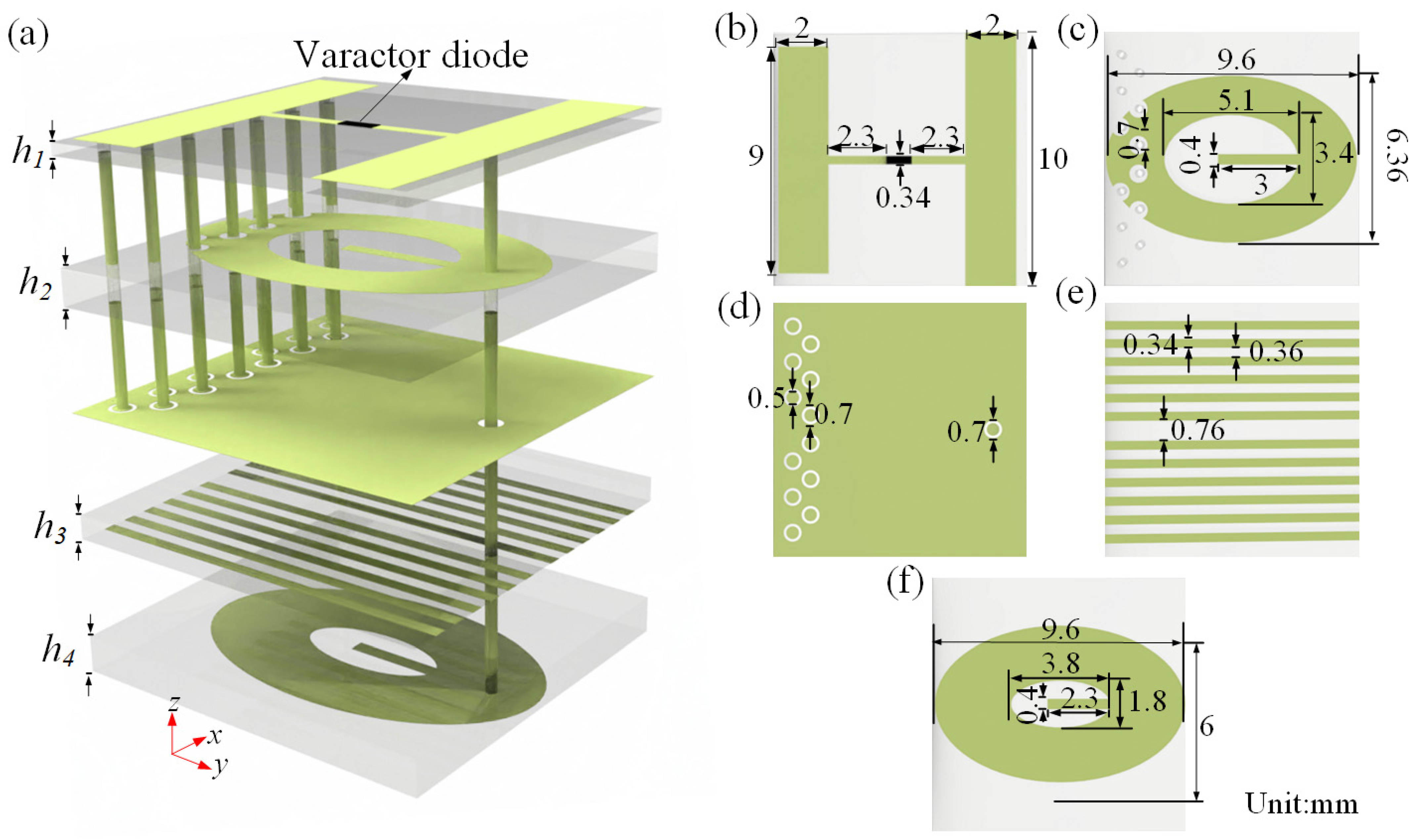
The unit cell of the reflection and transmission integrated programmable metasurface is shown in Figure 2. Each unit cell consists of five metal layers separated by four dielectric substrates with a dielectric constant of 3.58, with thicknesses of h1 = 1.2 mm, h2 = 1.5 mm, h3 = 0.6 mm, and h4 = 0.9 mm. As presented in Figure 2b, the first layer of the unit cell is an “H”-shaped metallic pattern. When an external electric field is applied vertically to the two metal strips on either side, a capacitive response is generated. The capacitance value of the varactor diode can be adjusted based on the bias voltage applied to both sides, enabling dynamic regulation of the response of the unit cell. Between the two metal strips, a MACOM MAVR-011020-1411 varactor diode (MACOM Technology Solutions Inc., Lowell, MA, USA)—featuring a dynamic capacitance range from 0.02 to 0.22 pF—is installed. Through the application of a reverse DC bias voltage to this electronic part, the overall capacitance of the metasurface can be accurately adjusted. For the purpose of independently controlling the electromagnetic response of each unit cell, one continuous side of the top-layer “H”-shaped metal structure is linked to the DC power supply’s ground terminal, and the other side is directly connected to the feedlines through twelve via holes.
The second layer is composed of an elliptical patch with a U-slot in the center, which is connected to the top and bottom layer via metallized through-holes, as shown in Figure 2c. The third layer is the continuous reflection layer, as illustrated in Figure 2d, which interacts with the metallic pattern on the first and the second layer for the reflection phase modulation, enabling the approximately 360° reflection phase coverage. As displayed in Figure 2e, the fourth layer is the feed layer containing twelve feed lines, which are connected to twelve via holes. Eleven of these are blind vias, while only one blind via is connected to the positive side of the DC voltage source. Regardless of the position of the unit cell within the metasurface, the structure above the continuous reflection layer remains unchanged, avoiding interference in the electromagnetic response caused by varying via positions. The bottom layer is the transmission layer, composed of an elliptical patch with a U-slot in the center, connected to the second layer via metallized vias as presented in Figure 2f.
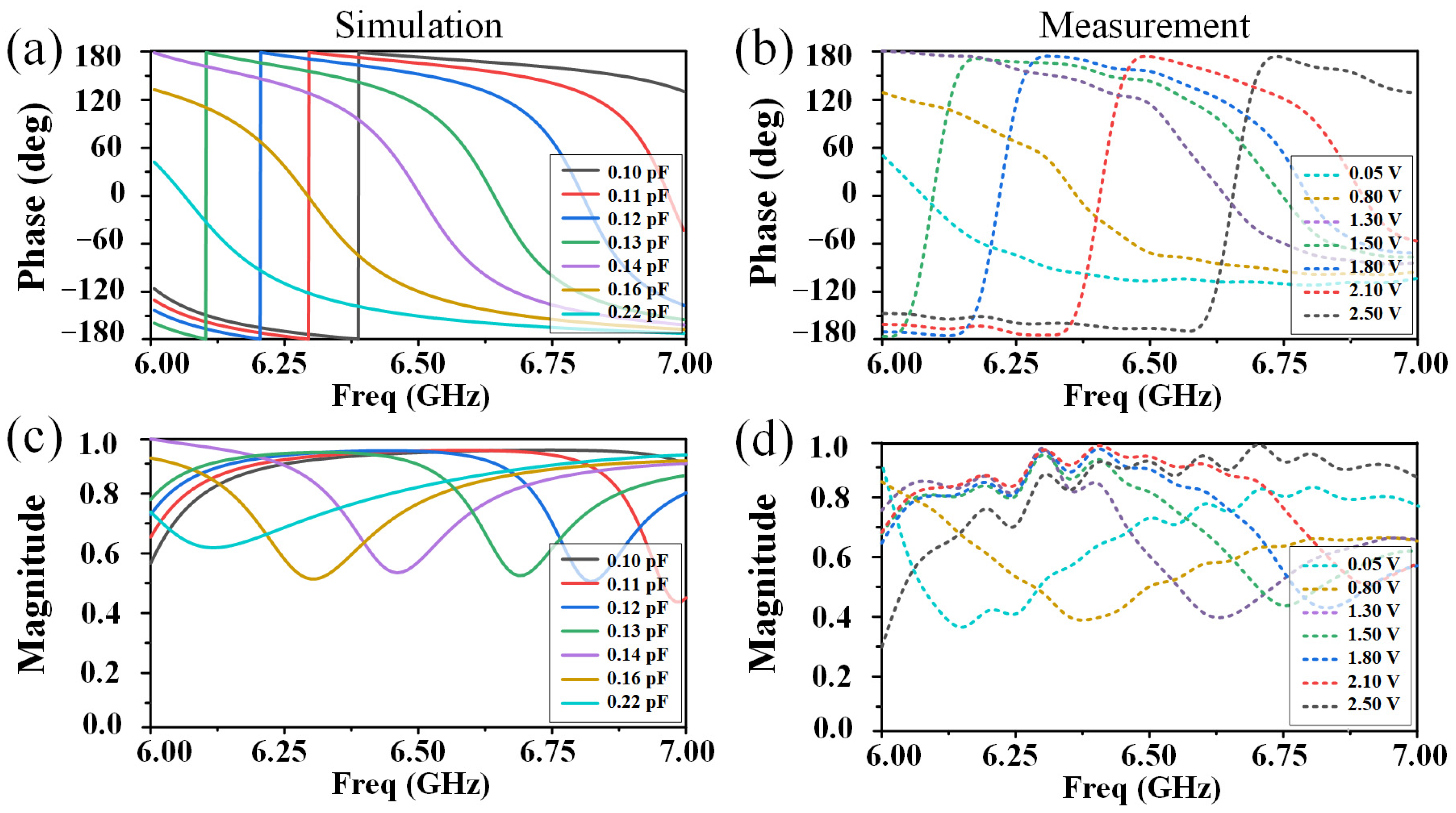
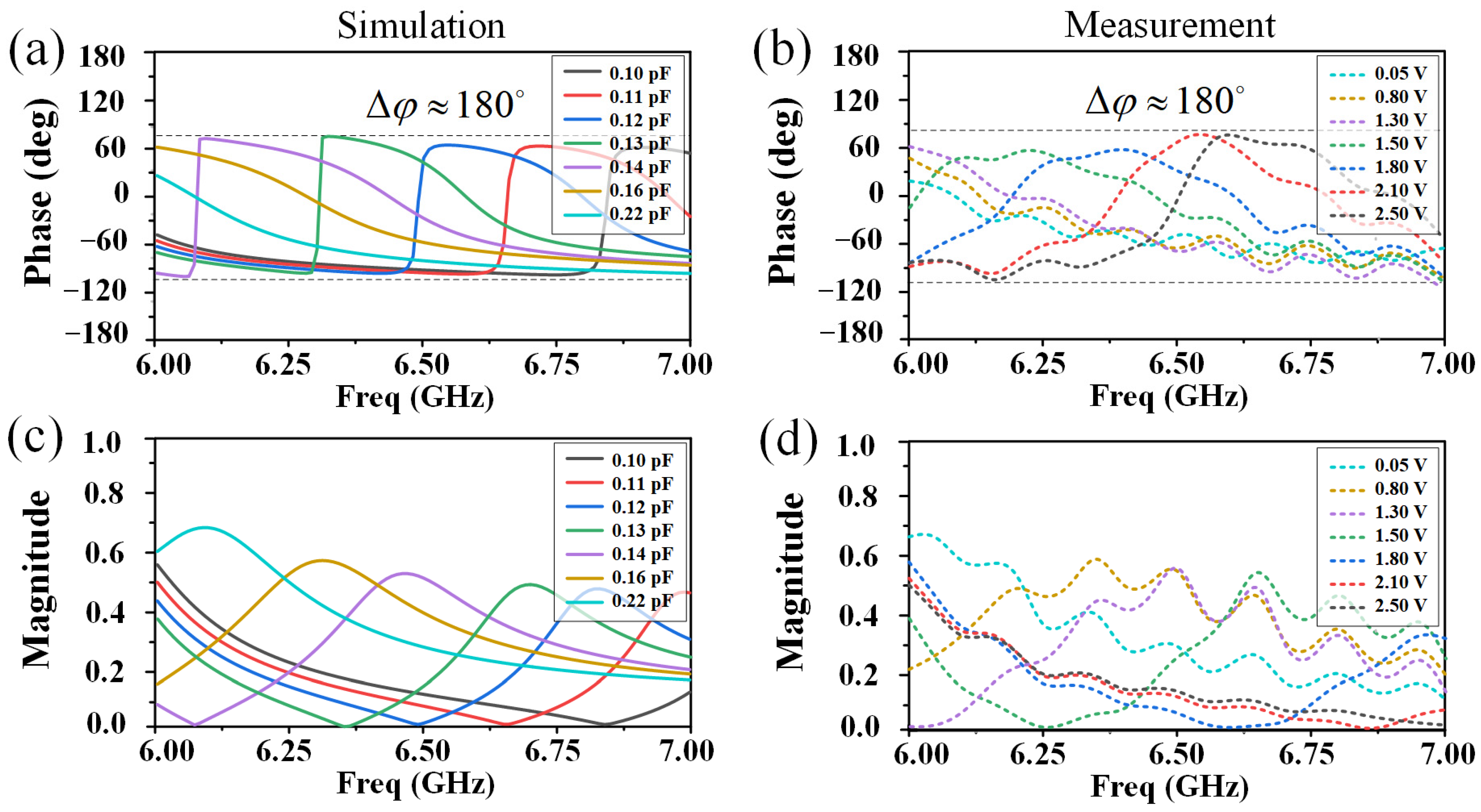
To systematically investigate the electromagnetic characteristics of the programmable unit cells, numerical simulations are conducted using the commercial software Ansys HFSS 2021 R1 version in the 6–7 GHz frequency range. The programmable unit cell model is constructed based on the finite-element method (FEM), and a Floquet excitation port is used to emit an incident plane wave perpendicular to the surface. RLC lumped parameter boundary is applied to the varactor diode. Master–slave boundary conditions are set along the x and y directions to mimic an infinite periodic boundary. Seven characteristic capacitance values are selected to show the reflection phase and amplitude response characteristics, as illustrated in Figure 3a,c. The simulated phase has a nearly 360° coverage in the frequency range from 6 GHz to 7 GHz. Seven voltages are selected to show the measured reflection responses, which are presented in Figure 3b,d. An approximately 360° coverage can be observed. The amplitude is higher than 0.38, which is not high due to the inherent loss of the varactor diode and substrate. The simulated transmission phase and amplitude response are shown in Figure 4a,c. The transmission phase can realize a nearly 180° coverage, which can be used for a 1-bit coding phase scheme. Similarly, the measured phase and amplitude responses are performed and shown in Figure 4b,d.

3. Principles and Results

The Airy beam bears a resemblance to the Airy wave packet solution, which describes a quantum particle in free space as laid out by the Schrödinger equation. A two-dimensional (2D) Airy beam can be generated by multiplying two one-dimensional (1D) Airy beams, with each accelerating along the x and y directions, respectively. The electric field envelope of a finite-energy 2D Airy beam can be formulated as [36]
ϕ A i r y ξ = 0 , x , y = A i ( a x ) A i ( a y ) e x p ( b x ) e x p ( b y )
where the two 1D Airy beams aligned along the x and y axes have the same parameters a and b. The parameter a is an arbitrary transverse scale, and parameter b is a positive number. The relationship between a and b is b = αa, where the exponential truncation factor is α (<< 1). Ai(ax) and Ai(ay) are Airy functions, and the normalized propagation distance along the z direction is denoted by ξ = za2/k. For the 2D Airy beam production, we take advantage of the 1-bit coding phase technique. The phase modulation profile is defined as fluctuating between 90° and +90° [36]:
φ A i r y ξ = 0 , x , y = a r g ϕ A i r y ξ = 0 , x , y π / 2
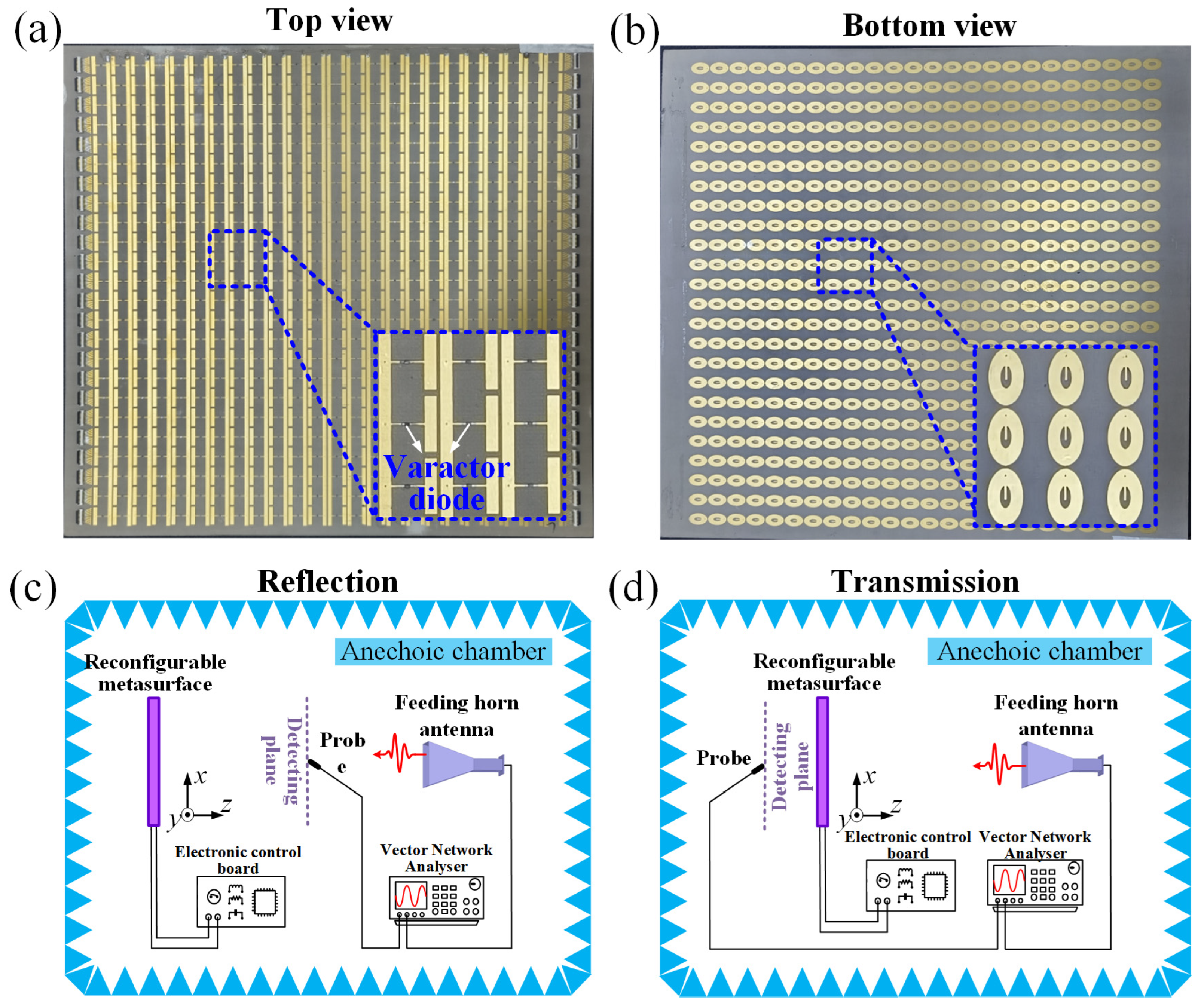
To numerically and experimentally realize the generation and regulation of the Airy beam, a 24 × 24 unit cell array is modeled to construct a dynamically programmable metasurface. For the Airy beam simulations, the Ansys HFSS based on the finite-element method (FEM) is used. Radiation boundary conditions are set around the metasurface to imitate an open-space electromagnetic environment, and plane waves are used as the excitation source. For the Airy beam measurements, the programmable metasurface prototype consisting of 24 × 24 unit cells is fabricated using printed circuit board (PCB) technology and surface mount technology (SMT), as shown in Figure 5a,b. The experimental verification platform schematics for both reflection and transmission are shown in Figure 5c,d, where a horn antenna operating at 2–18 GHz is used to generate a planar electromagnetic wave illuminating the metasurface. A microwave probe mounted on an intelligent mechanical slide rail could receive electric field information within a maximum 480 × 480 mm2 area under upper computer control. The measurement platforms are surrounded by absorptive materials to reduce electromagnetic environmental interference.
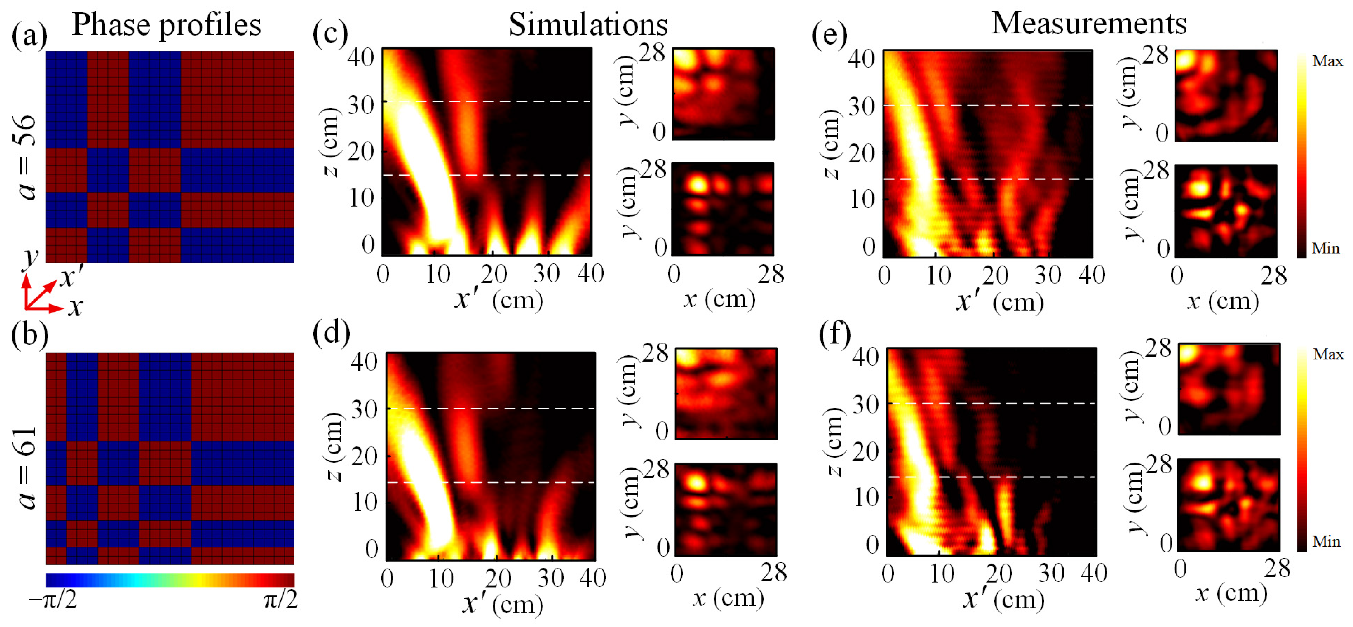
To investigate the aforementioned Airy beams generation using the programmable metasurface in the transmission space, two parameters, a = 56 and 61, are selected according to Equation (1). The phase profiles for generating Airy beams with parameters a = 56 and a = 61 are presented in Figure 6a and Figure 6b, respectively. These phase distributions are derived from Equation (2), utilizing a 1-bit coding scheme with phase states alternating between −π/2 and π/2, which aligns with the transmission phase coverage (nearly 180°) of the proposed metasurface. The axes x’ denotes the diagonal direction between the x and y axes. Numerical simulations of the two Airy beams in transmission space are presented in Figure 6c,d. The Airy beam with both parameters a = 56 and a = 61 exhibits a distinct self-bending trajectory, with the main lobe gradually deflecting from the propagation axis. The self-bending characteristic of the Airy beam can be evaluated via the deflection offset of the main lobe. Specifically, the deflection offset of the main lobe trajectory is defined as the difference between the central position of the main beam in the Airy profile and that of a hypothetical beam propagating in a straight line, which can be theoretically expressed as yd = λ2z2b3/16π2 [50]. Moreover, the electric field distributions in the two transverse planes z = 15 cm and 30 cm are presented in the subfigures, where we can see the acceleration along the x and y axes. The corresponding experimental measurements are carried out in an anechoic chamber, and the results are presented in Figure 6e,f. The observed beam patterns show a gently curved parabolic path and match their simulated counterparts well in terms of qualitative features. Small discrepancies between the simulation outcomes and actual measurements could stem from flaws in the measurement configuration and manufacturing tolerances. The consistency between simulations and measurements validates that the metasurface is capable of dynamically producing adjustable Airy beams in the transmission space through a 1-bit phase coding method.
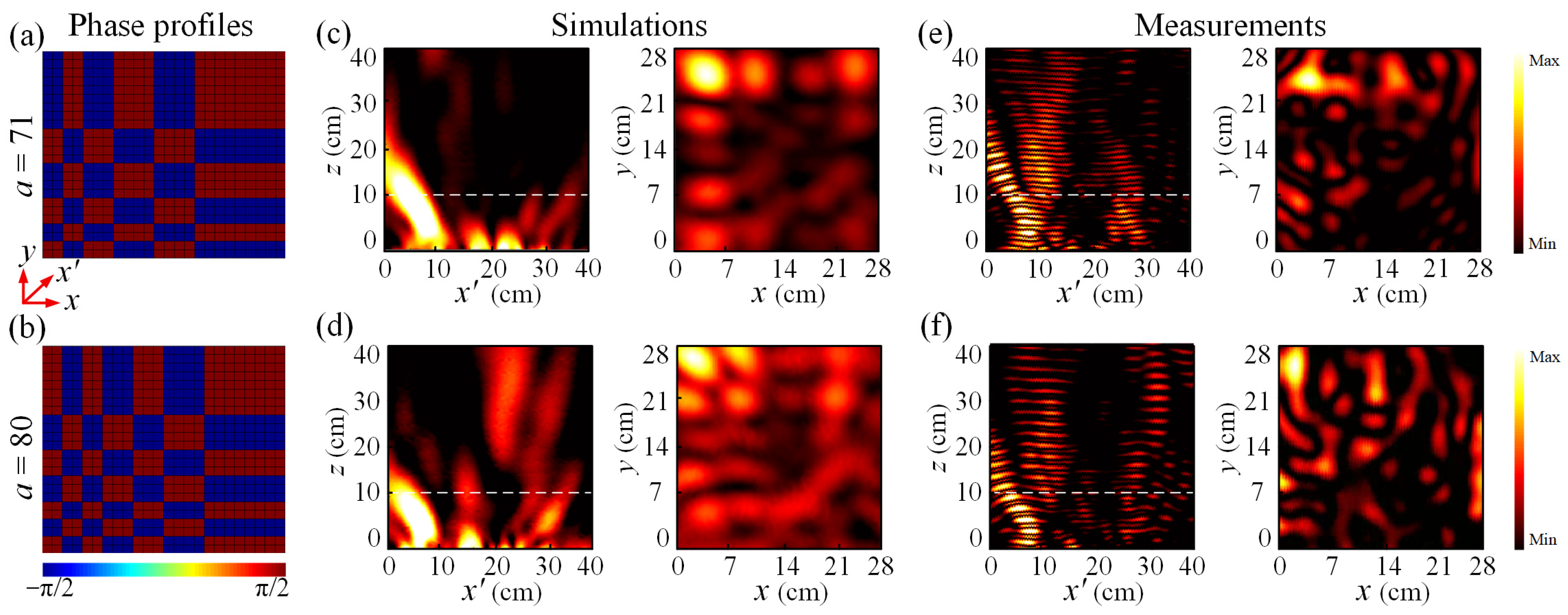
In the reflection space, although the programmable metasurface achieves approximately 360° phase coverage, the Airy beam generation is based on the 1-bit coding method according to Equation (2). The corresponding phase profiles for the Airy beam generation with parameters a = 71 and a = 81 are illustrated in Figure 7a,b. The simulated electric field distributions of the Airy beam in the x’oz and xoy planes are presented in Figure 7c,d. The curved propagation trajectory can be observed for both Airy beams in the x’oz plane. When the parameter a increases from 71 to 80, the curvature also increases clearly. The electric field distributions in the transverse plane z = 10 cm are displayed in the subfigures. The acceleration in both x and y directions can be observed for the two reflected Airy beams. The experimental measurements are shown in Figure 7e,f. The main beams of the Airy beams propagate along a curved trajectory, which is consistent with the numerical simulations. Both transmission and reflection measurements validate the metasurface’s capability to dynamically generate and manipulate Airy beams across the full space. The tunability via parameter a and excellent agreement between simulations and experiments highlight the proposed platform’s potential for applications in adaptive optics, wireless power transfer, and particle manipulation.

4. Conclusions

In this work, we realize the dynamic generation and manipulation of Airy beams in both reflection and transmission spaces using a full-space programmable metasurface. The proposed metasurface achieves approximately 360° phase coverage in the reflection space and nearly 180° phase coverage in the transmission space within the 6–7 GHz frequency band, facilitated by varactor diodes integrated into its unit cells and precise DC bias voltage control. Numerical simulations and experimental measurements at 6.5 GHz confirm the effectiveness of the design. In the transmission space, 1-bit phase coding based on 180° phase coverage successfully generates Airy beams with characteristic self-bending, self-accelerating, and non-diffracting properties, with simulated and measured beam profiles showing good agreement. In the reflection space, two Airy beams are achieved at 6.5 GHz with the unique characteristics of the Airy beams. The proposed full-space programmable metasurface platform for Airy beam generation paves the way for diverse applications, including optical particle manipulation, controllable wireless energy transmission, and complex terrain exploration, where dynamic, space-efficient, and multi-functional beam control is critical. Future work will focus on extending the operating frequency range, reducing insertion loss, and exploring multi-beam generation capabilities to further expand its application potential.

Author Contributions

Conceptualization, R.F. and Q.T.; methodology, J.W.; software, Y.Y.; validation, Y.Y., L.W. and Z.L.; formal analysis, R.F.; investigation, Q.T.; resources, Y.Y.; data curation, J.W.; writing—original draft preparation, R.F.; writing—review and editing, Q.T.; visualization, Y.Y.; supervision, Q.T.; project administration, R.F.; funding acquisition, Q.T. All authors have read and agreed to the published version of the manuscript.

Funding

This research was funded by Fundamental Research Program of Shanxi Province, grant numbers 202203021222070, 202203021222022, and 202403021212023; National Natural Science Foundation of China, grant number 62401522; Regional Innovation and Development Joint Fund, grant number U24A20136; and Research Project Supported by Shanxi Scholarship Council of China.

Institutional Review Board Statement

Not applicable.

Informed Consent Statement

Not applicable.

Data Availability Statement

The original contributions presented in the study are included in the article, further inquiries can be directed to the corresponding author.

Conflicts of Interest

The authors declare no conflicts of interest.

Abbreviations

The following abbreviations are used in this manuscript:
DCDirect current
SLMsSpatial light modulators
LCLiquid crystal
PCBPrinted circuit board
2DTwo-dimensional
FEMFinite-element method
SMTSurface mount technology

References

  1. Besieris, I.M.; Shaarawi, A.M. A note on an accelerating finite energy Airy beam. Opt. Lett. 2007, 32, 2447–2449. [Google Scholar] [CrossRef]
  2. Márkus, F.; Gambár, K. Quantized Approach to Damped Transversal Mechanical Waves. Quantum Rep. 2024, 6, 120–133. [Google Scholar] [CrossRef]
  3. Zhang, Z.; Zhang, P.; Mills, M.; Chen, Z.; Christodoulides, D.; Liu, J. Trapping aerosols with optical bottle arrays generated through a superposition of multiple Airy beams. Chin. Opt. Lett. 2013, 11, 033502. [Google Scholar] [CrossRef]
  4. Wang, J.; Zuo, Y.; Wang, X.; Christodoulides, D.N.; Siviloglou, G.A.; Chen, J.F. Spatiotemporal single-photon Airy bullets. Phys. Rev. Lett. 2024, 132, 143601. [Google Scholar] [CrossRef]
  5. Călin, B.Ş.; Preda, F.; Jipa, F.; Zamfirescu, M. Laser fabrication of diffractive optical elements based on detour-phase computer-generated holograms for two-dimensional Airy beams. Appl. Opt. 2018, 57, 1367. [Google Scholar] [CrossRef]
  6. Berry, M.V.; Balazs, N.L. Nonspreading wave packets. Am. J. Phys. 1979, 47, 264. [Google Scholar] [CrossRef]
  7. Siviloglou, G.A.; Christodoulides, D.N. Accelerating finite energy Airy beams. Opt. Lett. 2007, 32, 979–981. [Google Scholar] [CrossRef] [PubMed]
  8. Luo, D.; Dai, H.T.; Sun, X.W.; Demir, H.V. Electrically switchable finite energy Airy beams generated by a liquid crystal cell with patterned electrode. Opt. Commun. 2010, 283, 3846–3849. [Google Scholar] [CrossRef]
  9. Jia, S.; Vaughan, J.C.; Zhuang, X. Isotropic three-dimensional super resolution imaging with a self-bending point spread function. Nat. Photonics 2014, 8, 302–306. [Google Scholar] [CrossRef]
  10. Vettenburg, T.; Dalgarno, H.I.C.; Nylk, J.; Coll-Llado, C.; Ferrier, D.E.K.; Cizmar, T.; Gunn-Moore, F.J.; Dholakia, K. Light-sheet microscopy using an Airy beam. Nat. Methods 2014, 11, 541–544. [Google Scholar] [CrossRef]
  11. Liu, K.; Koulouklidis, A.D.; Papazoglou, D.G.; Tzortzakis, S.; Zhang, X. Enhanced terahertz wave emission from air-plasma tailored by abruptly autofocusing laser beams. Optica 2016, 3, 605–608. [Google Scholar] [CrossRef]
  12. Siviloglou, G.A.; Broky, J.; Dogariu, A.; Christodoulides, D.N. Ballistic dynamics of Airy beams. Opt. Lett. 2008, 33, 207–209. [Google Scholar] [CrossRef]
  13. Ren, Z.; Wu, Q.; Shi, Y.; Chen, C.; Wu, J.; Wang, H. Production of accelerating quad Airy beams and their optical characteristics. Opt. Express 2014, 22, 15154–15164. [Google Scholar] [CrossRef]
  14. Cottrell, D.M.; Davis, J.A.; Hazard, T.M. Direct generation of accelerating Airy beams using a 3/2 phase-only pattern. Opt. Lett. 2009, 34, 2634–2636. [Google Scholar] [CrossRef]
  15. Salandrino, A.; Christodoulides, D.N. Airy Plasmon: A Non-Diffracting Surface Wave. Opt. Lett. 2010, 35, 2082–2084. [Google Scholar] [CrossRef] [PubMed]
  16. Cao, R.; Yang, Y.; Wang, J.G.; Bu, J.; Wang, M.W.; Yuan, X.C. Microfabricated continuous cubic phase plate induced Airy beams for optical manipulation with high power efficiency. Appl. Phys. Lett. 2011, 99, 261106. [Google Scholar] [CrossRef]
  17. Acebal, P.; Carretero, L.; Blaya, S.; Murciano, A. Generation of High-Quality Tunable One-Dimensional Airy Beams Using the Aberrations of a Single Lens. IEEE Photonics J. 2012, 4, 1273–1280. [Google Scholar] [CrossRef]
  18. Niu, L.; Liu, C.; Wu, Q.; Wang, K.; Yang, Z.; Liu, J. Generation of One Dimensional Terahertz Airy Beam by Three-Dimensional Printed Cubic Phase Plate. IEEE Photonics J. 2017, 9, 1–7. [Google Scholar] [CrossRef]
  19. Cai, Z.; Liu, Y.; Zhang, C.; Xu, J.; Ji, S.; Ni, J.; Li, J.; Hu, Y.; Wu, D.; Chu, J. Continuous cubic phase microplates for generating high-quality Airy beams with strong deflection. Opt. Lett. 2017, 42, 2483–2486. [Google Scholar] [CrossRef]
  20. Wei, B.; Chen, P.; Hu, W.; Ji, W.; Zheng, L.; Ge, S.; Ming, Y.; Chigrinov, V.; Lu, Y. Polarization-controllable Airy beams generated via a photoaligned director-variant liquid crystal mask. Sci. Rep. 2015, 5, 17484. [Google Scholar] [CrossRef]
  21. Yalizay, B.; Soylu, B.; Akturk, S. Optical element for generation of accelerating Airy beams. J. Opt. Soc. Am. A 2010, 27, 2344–2346. [Google Scholar] [CrossRef]
  22. Papazoglou, D.G.; Suntsov, S.; Abdollahpour, D.; Tzortzakis, S. Tunable intense Airy beams and tailored femtosecond laser filaments. Phys. Rev. A 2010, 81, 061807. [Google Scholar] [CrossRef]
  23. Fan, S.; Zhu, Y.; Cao, L.; Wang, Y.; Chen, A.; Merkel, A.; Wang, Y.; Assouar, B. Broadband tunable lossy metasurface with independent amplitude and phase modulations for acoustic holography. Smart Mater. Struct. 2020, 29, 105038. [Google Scholar] [CrossRef]
  24. Yu, N.F.; Capasso, F. Flat optics with designer metasurfaces. Nat. Mater. 2014, 13, 139–150. [Google Scholar] [CrossRef]
  25. Chen, H.T.; Taylor, A.J.; Yu, N.F. A review of metasurfaces: Physics and applications. Rep. Prog. Phys. 2016, 79, 076401. [Google Scholar] [CrossRef]
  26. Yu, N.; Genevet, P.; Kats, M.A.; Aieta, F.; Tetienne, J.-P.; Capasso, F.; Gaburro, Z. Light Propagation with Phase Discontinuities: Generalized Laws of Reflection and Refraction. Science 2011, 334, 333–337. [Google Scholar] [CrossRef] [PubMed]
  27. Enoch, S.; Tayeb, G.; Sabouroux, P.; Guerin, N.; Vincent, P. A metamaterial for directive emission. Phys. Rev. Lett. 2002, 89, 213902. [Google Scholar] [CrossRef]
  28. Ullah, M.; Islam, M.; Faruque, M. A Near-Zero Refractive Index Meta-Surface Structure for Antenna Performance Improvement. Materials 2013, 6, 5058–5068. [Google Scholar] [CrossRef]
  29. Choi, M.; Lee, S.H.; Kim, Y.; Kang, S.B.; Shin, J.; Kwak, M.H.; Kang, K.Y.; Lee, Y.H.; Park, N.; Min, B. A terahertz metamaterial with unnaturally high refractive index. Nature 2011, 470, 369–373. [Google Scholar] [CrossRef]
  30. Liu, R.; Cheng, Q.; Hand, T.; Mock, J.J.; Cui, T.J.; Cummer, S.A.; Smith, D.R. Experimental Demonstration of Electromagnetic Tunneling Through an Epsilon-Near-Zero Metamaterial at Microwave Frequencies. Phys. Rev. Lett. 2008, 100, 023903. [Google Scholar] [CrossRef]
  31. Cui, Y.; Fung, K.H.; Xu, J.; Ma, H.; Jin, Y. Ultra-broadband Light Absorption by a Sawtooth Anisotropic Metamaterial Slab. Nano Lett. 2011, 12, 1443–1447. [Google Scholar] [CrossRef] [PubMed]
  32. Hong, Q.R.; Ma, Q.; Gao, X.X.; Liu, C.; Xiao, Q.; Iqbal, S.; Cui, T.J. Programmable Amplitude-Coding Metasurface with Multifrequency Modulations. Adv. Intell. Syst. 2021, 3, 2000260. [Google Scholar] [CrossRef]
  33. Ratni, B.; Merzouk, W.A.; de Lustrac, A.; Villers, S.; Piau, G.P.; Burokur, S.N. Design of Phase-Modulated Metasurfaces for Beam Steering in Fabry-Perot Cavity Antennas. IEEE. Antennas Wirel. Propag. Lett. 2017, 16, 1401–1404. [Google Scholar] [CrossRef]
  34. Yang, H.H.; Cao, X.Y.; Yang, F.; Gao, J.; Xu, S.H.; Li, M.K.; Chen, X.B.; Zhao, Y.; Zheng, Y.J.; Li, S.J. A programmable metasurface with dynamic polarization, scattering and focusing control. Sci. Rep. 2016, 6, 35692. [Google Scholar] [CrossRef]
  35. Germain, D.; Seetharamdoo, D.; Burokur, S.N.; de Lustrac, A. Phase-compensated metasurface for a conformal microwave antenna. Appl. Phys. Lett. 2013, 103, 124102. [Google Scholar] [CrossRef]
  36. Feng, R.; Ratni, B.; Yi, J.; Zhang, H.; de Lustrac, A.; Burokur, S.N. Versatile metasurface platform for electromagnetic wave tailoring. Photonics Res. 2021, 9, 1650–1659. [Google Scholar] [CrossRef]
  37. Li, S.; Tsakmakidis, K.L.; Jiang, T.; Shen, Q.; Zhang, H.; Yan, J.; Sun, S.; Shen, L. Unidirectional guided-wave-driven metasurfaces for arbitrary wavefront control. Nat. Commun. 2024, 15, 5992. [Google Scholar] [CrossRef]
  38. Saadat, S.; Mosallaei, H.; Afshari, E. Radiation-efficient 60 GHz on-chip dipole antenna realised by reactive impedance metasurface. IET Microw. Antennas Propag. 2013, 7, 98–104. [Google Scholar] [CrossRef]
  39. Jansen, C.; Al-Naib, I.A.I.; Born, N.; Koch, M. Terahertz metasurfaces with high Q-factors. Appl. Phys. Lett. 2011, 98, 051109. [Google Scholar] [CrossRef]
  40. Farmahini-Farahani, M.; Mosallaei, H. Birefringent reflectarray metasurface for beam engineering in infrared. Opt. Lett. 2013, 38, 462–464. [Google Scholar] [CrossRef]
  41. Wang, Z.H.; He, S.M.; Liu, Q.F.; Wang, W. Visible light metasurfaces based on gallium nitride high contrast gratings. Opt. Commun. 2016, 367, 144–148. [Google Scholar] [CrossRef]
  42. Chai, Y.; Deng, H.; Xiong, Q.X. A Dynamically Phase Tunable Metasurface for a Broad Bandwidth Ultra-Low Radar Cross Section. IEEE Access 2020, 8, 53006–53017. [Google Scholar] [CrossRef]
  43. de Lustrac, A.; Ratni, B.; Piau, G.P.; Duval, Y.; Burokur, S.N. Tri-state Metasurface-Based Electromagnetic Screen with Switchable Reflection, Transmission, and Absorption Functionalities. ACS Appl. Electron. Mater. 2021, 3, 1184–1190. [Google Scholar] [CrossRef]
  44. Liu, S.; Xu, H.X.; Zhang, H.C.; Cui, T.J. Tunable ultrathin mantle cloak via varactor-diode-loaded metasurface. Opt. Express 2014, 22, 13403–13417. [Google Scholar] [CrossRef] [PubMed]
  45. Selvaraj, M.; Vijay, R.; Anbazhagan, R.R.; Amirtharajan. Reconfigurable Metasurface: Enabling Tunable Reflection in 6G Wireless Communications. Sensors 2023, 23, 9166. [Google Scholar] [CrossRef] [PubMed]
  46. Dai, J.Y.; Zhao, J.; Cheng, Q.; Cui, T.J. Independent control of harmonic amplitudes and phases via a time-domain digital coding metasurface. Light-Sci. Appl. 2018, 7, 90. [Google Scholar] [CrossRef]
  47. Chen, K.; Feng, Y.J.; Monticone, F.; Zhao, J.M.; Zhu, B.; Jiang, T.; Zhang, L.; Kim, Y.; Ding, X.M.; Zhang, S.; et al. A Reconfigurable Active Huygens’ Metalens. Adv. Mater. 2017, 29, 1606422. [Google Scholar] [CrossRef]
  48. Wolff, A.; Franke, L.; Klingel, S.; Krieger, J.; Mueller, L.; Stemler, R.; Rahm, M. Continuous beam steering with a varactor-based reconfigurable intelligent surface in the Ka-band at 31 GHz. J. Appl. Phys. 2023, 134, 114502. [Google Scholar] [CrossRef]
  49. Phon, R.; Lee, M.; Lor, C.; Lim, S. Multifunctional Reflective Metasurface to Independently and Simultaneously Control Amplitude and Phase with Frequency Tunability. Adv. Opt. Mater. 2023, 11, 2202943. [Google Scholar] [CrossRef]
  50. Feng, R.; Ratni, B.; Yi, J.; Zhang, K.; Ding, X.; Zhang, H.; de Lustrac, A.; Burokur, S.N. Versatile Airy-beam generation using a 1-bit coding programmable reflective metasurface. Phys. Rev. Appl. 2020, 14, 014081. [Google Scholar] [CrossRef]
  51. Gao, M.; Wang, J.; Cai, W.; Cheng, M.; Hao, X.; Wang, Y.; Liu, Y.; Kong, D.; Liu, J.; Dai, H.; et al. Dynamic propagation of an Airy beam in metasurface-enabled gradiently-aligned liquid crystals. Nanophotonics 2023, 12, 4205–4214. [Google Scholar] [CrossRef] [PubMed]
  52. Zhou, Z.; Zhang, R.; Chen, Z.; Nie, R.; Pan, Z.; Song, Z. Terahertz generation of Airy beam with polarization conversion in a reflective vanadium dioxide metasurface. Phys. Scr. 2024, 99, 055555. [Google Scholar] [CrossRef]
  53. Ma, H.; Dai, Y.; Feng, X.; Wang, X.; Fang, J.; Wang, Q.; Zhang, Y.; Liu, H. An Optically Controlled Programmable Metasurface Based on Complex Amplitude Modulation for Dynamic Generation of Airy and Vortex Beams. Opt. Commun. 2025, 592, 132254. [Google Scholar] [CrossRef]
Figure 1. Schematic diagram of the full-space Airy beam generation when the reflection–transmission integrated programmable metasurface is illuminated by a y-polarized quasi-plane-wave emitted by a microwave horn antenna.
Applsci 15 09177 g001
Figure 2. The geometric characteristics and corresponding parameters of the programmable unit cell. (a) The 3D perspective view of the unit cell. (bf) Details of each metal layer.
Applsci 15 09177 g002
Figure 3. Numerical and experimental reflection responses of the designed unit cell in the frequency band changing from 6 GHz to 7 GHz. (a) Numerically simulated reflection phase response for different capacitance values. (b) Experimentally measured reflection phase response for different bias voltage values. (c) Numerically simulated reflection amplitude response for different capacitance values. (d) Experimentally measured reflection amplitude response for different bias voltage values.
Applsci 15 09177 g003
Figure 4. Numerical and experimental transmission responses of the designed unit cell in the frequency band changing from 6 GHz to 7 GHz. (a) Numerically simulated transmission phase response for different capacitance values. (b) Experimentally measured transmission phase response for different bias voltage values. (c) Numerically simulated transmission amplitude response for different capacitance values. (d) Experimentally measured transmission amplitude response for different bias voltage values.
Applsci 15 09177 g004
Figure 5. Photographs of transmission–reflection-integrated programmable metasurface and schematic illustration of the experimental measurement setups. (a) Top view of the programmable metasurface. (b) Bottom view of the programmable metasurface. (c) Schematic setup for the electric field measurement in the reflection space. (d) Schematic setup for the electric field measurement in the transmission space.
Applsci 15 09177 g005
Figure 6. Simulations and measurements of the Airy beams in the transmission space at 6.5 GHz. (a) Phase profile of the Airy beam with parameter a = 56. (b) Phase profile of the Airy beam with parameter a = 56. (c) Simulated results of the Airy beam with parameter a = 56. (d) Simulated results of the Airy beam with parameter a = 61. (e) Measured results of the Airy beam with parameter a = 56. (f) Measured results of the Airy beam with parameter a = 61.
Applsci 15 09177 g006
Figure 7. Simulations and measurements of the Airy beams in the reflection space at 6.5 GHz. (a) Phase profile of the Airy beam with parameter a = 71. (b) Phase profile of the Airy beam with parameter a = 80. (c) Simulated results of the Airy beam with parameter a = 71. (d) Simulated results of the Airy beam with parameter a = 80. (e) Measured results of the Airy beam with parameter a = 71. (f) Measured results of the Airy beam with parameter a = 80.
Applsci 15 09177 g007
Table 1. Comparison of the Airy beam generator based on the tunable metasurface.
Ref.Frequency BandwidthTypeElectronic ComponentModulation Along Metasurface
[50]9–12 GHzReflectionVaractor diodesPhase
[51]632.8 nmInsideLiquid crystalPhase
[52]0.9–1.2 THzReflectionVanadium dioxidePhase and Amplitude
[53]1.64 THzReflectionPhotosensitive siliconPhase and Amplitude
This work6–7 GHzFull spaceVaractor diodesPhase
Disclaimer/Publisher’s Note: The statements, opinions and data contained in all publications are solely those of the individual author(s) and contributor(s) and not of MDPI and/or the editor(s). MDPI and/or the editor(s) disclaim responsibility for any injury to people or property resulting from any ideas, methods, instructions or products referred to in the content.