1. Introduction
The centrifugal pump, which plays a crucial role in energy conversion, is widely used in both agricultural and industrial applications. To reduce equipment costs and energy consumption, modern pump designs focus on improving performance parameters such as flow rate, rotational speed, head, and overall efficiency. However, with increasing energy throughput, vibration problems in centrifugal pumps become more pronounced, adversely affecting operational safety, performance stability, and equipment lifespan. This issue is particularly critical in the rotor assembly, where excessive vibrations can lead to severe damage to fast-rotating components such as the shaft, impeller, and bearings.
Rotor vibrations are mainly influenced by two types of factors: mechanical and hydraulic [
1,
2,
3,
4,
5]. Mechanical factors are typically associated with mass imbalance of rotating elements, shaft misalignment, and radial forces generated by the fluid flow [
6,
7].
To ensure the normal, efficient, and safe operation of such systems, many researchers have conducted both experimental and numerical studies to investigate vibrations caused by excitation parameters such as imbalance, external flow-induced forces, and operational conditions. Experimental studies [
8,
9,
10,
11,
12] have examined the effects of operational conditions on the dynamic behavior of pumps, and authors have concluded that operational factors such as impeller clogging, damaged impeller blades, and cavitation can significantly increase pump vibrations in the axial direction.
The general characteristics of imbalance issues in electric motors and centrifugal pumps, as well as the vibrations induced by these factors, have been investigated in studies [
13,
14], discovering that imbalance-related frequencies can lead to significant vibration responses. As a result, the authors proposed recommendations for identifying imbalance using vibration analysis techniques, along with damping methods employing a single-span cantilever structure.
The influence of flow rate was experimentally investigated in study [
15]. Based on vibration measurements, it was determined that within the designed flow range, the vibration amplitude remains relatively constant and does not exhibit significant changes with increasing flow rate. However, a noticeable increase in vibration levels becomes evident once the flow rate exceeds its nominal value.
The effect of damping properties of materials on the vibration characteristics of automotive pumps was investigated in study [
16]. It was found that the maximum deformation and natural frequency of Nylon-6 are lower when compared to cast iron (CI) or mild steel.
While emphasizing the importance of such studies for a deeper understanding of the causes of vibration, it is necessary to highlight a key drawback: targeted experimental investigations mainly describe the consequences of already manifested vibration processes and do not provide a predictive analysis of their causes or potential mitigation strategies at the pump design stage.
Over the past decades, numerous software tools have been developed to address the dynamic behavior of rotating machinery. Today, computer modeling and virtual prototyping are integral components of any engineering solution. A common challenge is how to create a virtual prototype (VP) such that the results of its mathematical simulation correspond to physical values or those obtained through experimental measurements [
17,
18,
19].
Various approaches to constructing computational models of pump dynamics have been presented in previous studies. For instance, D’Addio et al. [
20] developed an analytical model in which all components, except for the supports, were considered rigid. Unfortunately, the author did not validate the computational model against a physical prototype.
In the work by Hehui Zhang [
21], a computational model was developed that combined a CFD model with a rotor dynamic model; however, the finite element model (FEM) of the rotor did not take into account the effects of unbalance force. Verification of this computational experiment showed that the blade passing frequency (BPF) is the dominant factor influencing the dynamic response characteristics. The author emphasizes that the discrepancy between the computational and experimental data is related to the limitations of the software’s functionality. The information on bearing vibration is directly affected by the restricted types of elements available in the finite element rotordynamic model.
In study [
22], a prototype of a single-stage centrifugal pump with single-sided suction and both closed and open impeller types was modeled using ICEM CFD and ANSYS Workbench. The model incorporated fluid domain calculations. Comparison of the dynamic deformation of the impeller rotor system showed that the closed impeller exhibited superior stability and better hydraulic performance compared to the open-blade impeller. This study was aimed at analyzing the influence of head characteristics on pump efficiency and rotor deformation during modal analysis. However, the model does not account for the dynamic characteristics of the rotor supports and their effect on the system’s vibrations. A transient analysis was carried out in [
23] to investigate dynamic stresses and vibration in the volute casing of a large double-suction centrifugal pump. The authors created a finite element model using ANSYS and performed both static and dynamic analysis. In study [
24], modal analysis of a seven-stage centrifugal pump rotor system was performed using the finite element method (FEM) in ANSYS Workbench 18.2. It was found that vibration periods at the bearing are associated with shaft rotation frequency (SF) and blade passing frequency (BPF). Computational modeling of pump dynamics using ANSYS CFX 2020 [
25] showed that the natural rotational frequency of the impeller when submerged in water is significantly lower than in air—approximately 0.35 to 0.46 times the impeller’s natural frequency in an air environment. In [
26], the authors used ANSYS (ADAMS View 2020) and Fluent to calculate the natural and critical rotational frequencies of the rotor system. It was concluded that increasing rotational speed does not induce severe fluid vibration within the pump. Studies [
23,
24,
25,
26] developed high-quality finite element models; however, the support characteristics, which significantly influence the dynamic behavior of the rotor, were not taken into account.
Unlike the aforementioned studies, the work presented in [
27] proposed a novel analytical method that integrates multibody dynamics and finite element analysis to model both transverse and torsional vibrations. The results indicated that transverse vibrations have a significant impact on the dynamics of a single-rotor system at lower motor speeds. As motor speed increases, system motion becomes more stable. Despite the originality of the approach, the authors once again relied solely on the built-in ADAMS software functions for bearing modeling, which limited the ability to perform parametric design of the pump rotor dynamics, particularly with respect to the influence of support damping and stiffness.
Previous researchers have employed various approaches to analyzing the vibrations of rotating machinery: some studies were based on analytical methods, while others used numerical techniques, including the finite element analysis (FEA) and the Finite Volume Method. However, the use of multibody dynamics (MBD) in such analyses has remained relatively underexplored to date. In this context, the development of computational models for studying the behavior of rotating machines—including the analysis of the influence of support dynamic characteristics—and the subsequent validation of these models using experimental results significantly improves the reliability of calculations and enables the prediction of rotor instability at the pump design stage. This, in turn, reduces the need for extensive experimental testing and the production of costly physical prototypes. The present study provides the initial results of developing a parametric rotor model that takes into account the stiffness and damping characteristics of the supports, enabling optimal parameter selection to enhance the reliability and vibration resistance of pumping equipment.
Research Object
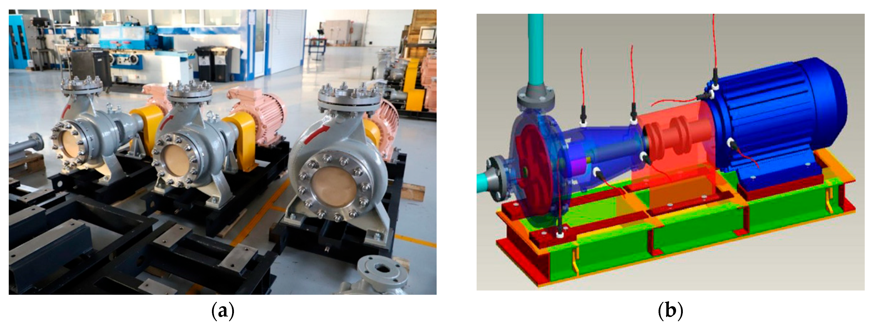
The object of this study is a centrifugal pump model CNR 32-160 model (
Figure 1), manufactured by the engineering company KARLSKRONA (Kazakhstan). The technical and geometrical specifications of the double-suction pump are as follows: motor power 0.75 kW, 1500 RPM, 3-phase, 380 V, head—5 m, and flow rate—8000 m
3/h. Water is used as the working fluid.
2. Materials and Methods
2.1. Construction of a Computer Rotor Dynamic Model of a Centrifugal Pump Rotor in MSC.ADAMS
The MSC.ADAMS software suite, equipped with a preprocessor, postprocessor, and solver in its basic package, converts the constructed model into equations of motion and solves them using numerical methods. Additionally, the package contains numerous specialized modules, each allowing the simulation of various systems and other mechanisms. It is important to note that the primary ADAMS solver is designed to solve problems concerning rigid body mechanics. Therefore, when modeling flexible structures—such as a vehicle frame—the software provides the capability to input modal parameters obtained from finite element packages like MSC.Nastran, ANSYS, and others.
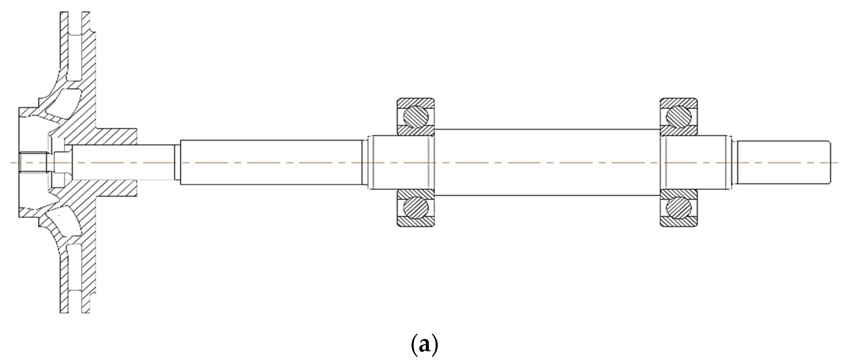
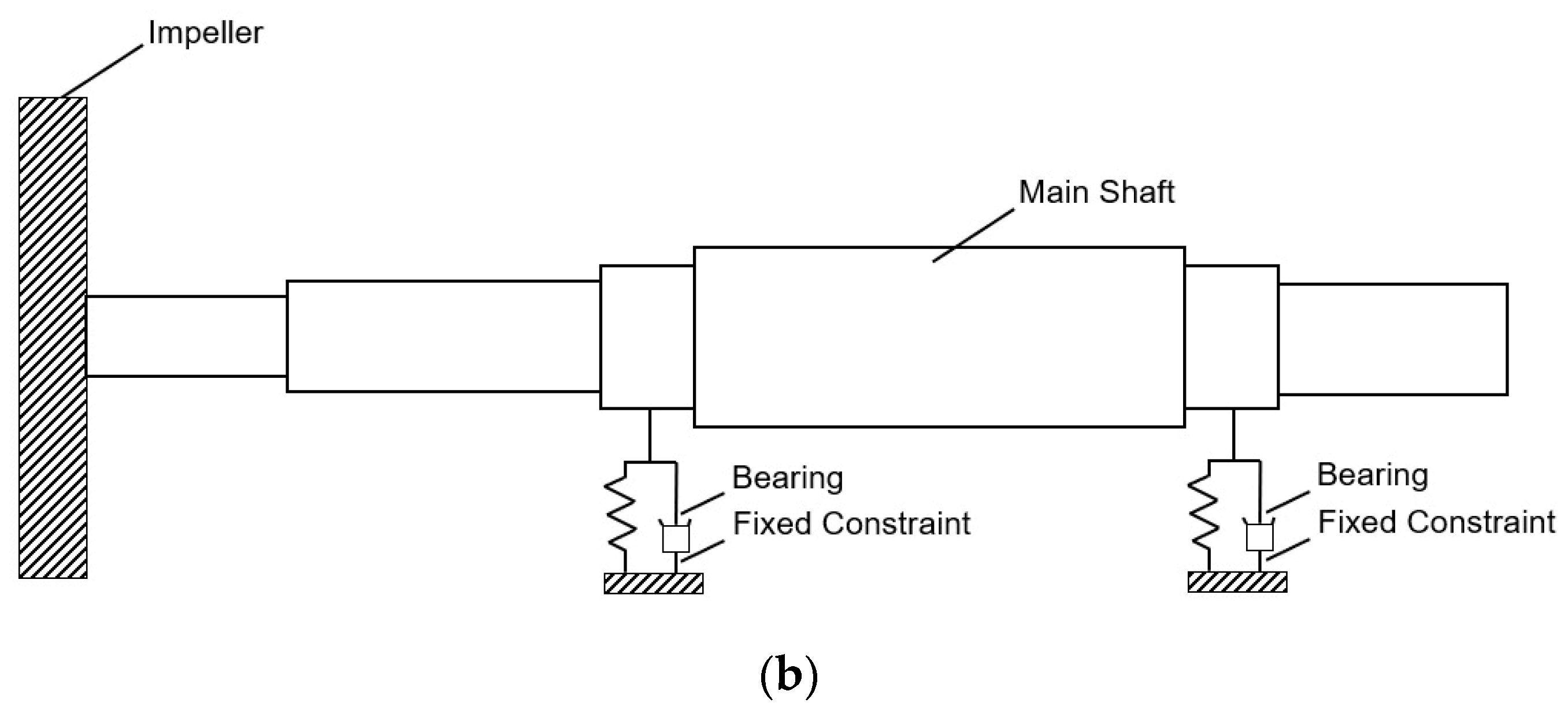
A rotor dynamic model of the centrifugal pump rotor, based on the Jeffcott rotor model [
28], was developed. As shown in
Figure 2, the typical dynamic rotor model consists of a main shaft, impeller, and two bearings.
In the ADAMS/View environment, a project database was created comprising the shaft, centrifugal impeller, and bearings. The shaft geometry and impeller were imported from INVENTOR software; this method of geometry creation in ADAMS/View most accurately reflects the complex geometric features of the impeller, enabling precise construction of the computational scheme related to the unbalance force [
29].
2.2. Theoretical Approaches of MBD (Multibody Dynamics)
By integrating MBD and CAD software environments, MBD analysis enables obtaining information about the motion state and loads of mechanical systems with non-trivial body geometries. The package implements several methods for formulating and solving systems of homogeneous differential equations, allowing the modeling of mechanisms with varying levels of complexity. The fundamental approach used in ADAMS is based on the second form of Lagrange’s equations, derived using the following expressions:
q—generalized coordinate;
F—general form of motion equations expressed in generalized coordinates;
L—Lagrangian (L = T − V), where T is kinetic energy and V is potential energy;
λ—Lagrange multiplier;
Q—generalized force;
n—number of generalized coordinates;
m—number of constraint equations (\or = n).
The derivation of the equations of motion for systems such as the SRS (single rotor system) was clearly explained by Yu [
16] based on Lagrange’s equations.
It should be noted that for each type of calculation, there are essential and non-essential parameters characterized by their degree of importance regarding the adequacy of the process description. For the analysis of the dynamic behavior of the system, the most important parameters are mass–inertial properties, elastic-damping characteristics (such as dampers and torsional shafts), and external forcing influences. In this type of analysis, geometry is primarily relevant in terms of correctly correlating the previously listed parameters [
30,
31,
32].
MBD modeling is performed according to the following algorithm:
- 1.
Defining the system’s kinematic constraints (see
Figure 3), which involves specifying components moving along predetermined paths.
The presented scheme illustrates the kinematic constraints used for modeling the dynamics of motions and restrictions between components of the mechanical system.
These constraints help accurately describe the interactions between mechanism parts and ensure the fulfillment of specified kinematic conditions.
- 2.
Modeling of Forces (Parametrically define where constraints or forces act; how the load is oriented in space and its vector components; and whether the load is predetermined—specified by the user).
The rotor
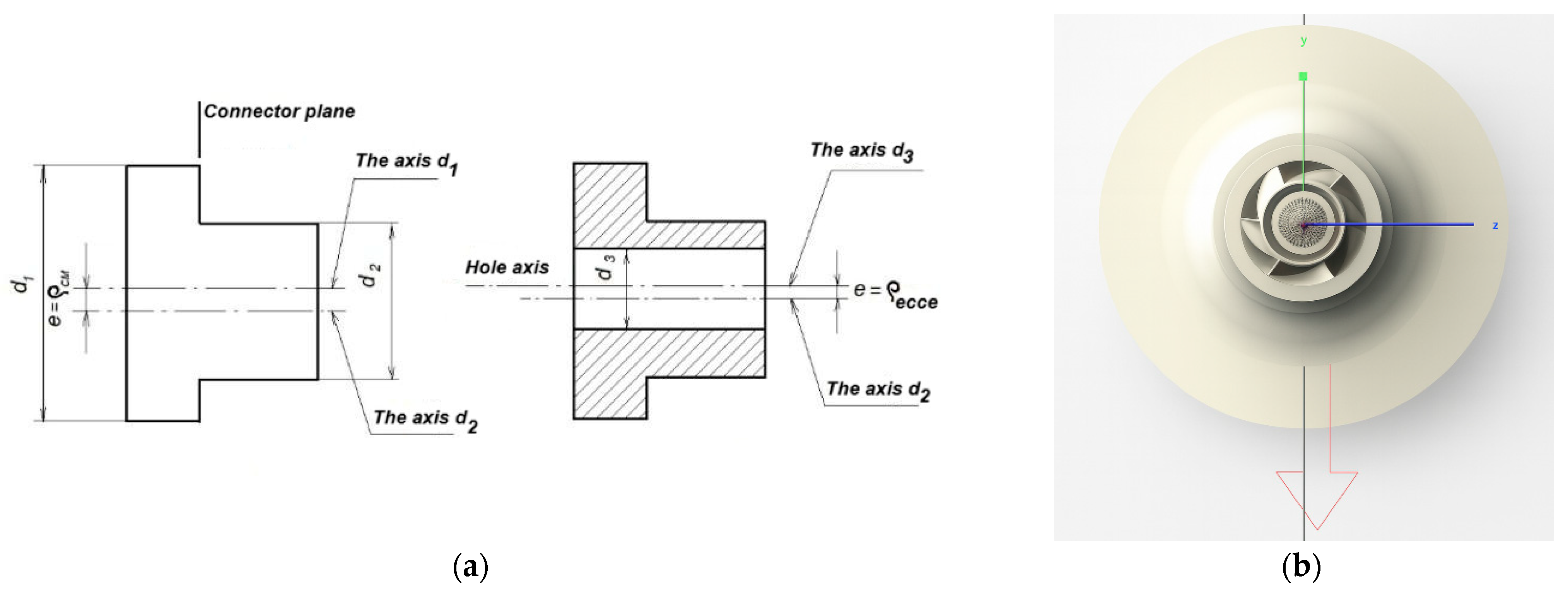
unbalance force is a dynamic force that arises due to an uneven mass distribution in the rotor, causing it to be displaced from the axis of rotation. This force induces vibrations and additional loads on the bearings and other structural components. It is caused by defects related to uneven material density or geometric deviations during rotor manufacturing. For example, the impellers are manufactured by stamping, which might generate eccentricities due to the misalignment of the stamping dies (ρ) (
Figure 4a).
Theoretically, the unbalance force is determined by the following formula:
where R is the amplitude of the unbalance force; m is the rotor mass; ω is the angular velocity; e is the specific unbalance (eccentricity) [
33,
34,
35].
Analytical determination of the unbalance magnitude is appropriate for static calculation schemes. The advantage of MBD systems lies in the automatic detection of the shifted center of mass and the visual marking of its position with a marker (
Figure 5). To investigate the influence of the unbalance force on the pump rotor vibration, we consider the impeller eccentricity according to
Table 1.
To this end, the marker’s location coordinates were adjusted by 0.075 mm along the z-axis. Despite the small value of the eccentricity, a simulation was carried out for two rotor rotation scenarios: with and without eccentricity. This allowed us to assess the influence of unbalance on the vibration of the pump rotor.
2.3. Hydraulic Force
The dynamics of the horizontal rotor of the centrifugal pump were studied under the influence of the following factors: gravitational force, unbalance force, and the hydrodynamic force exerted by the pumped fluid, i.e., water.
Figure 5 shows the impeller with the applied loads [
36,
37,
38].
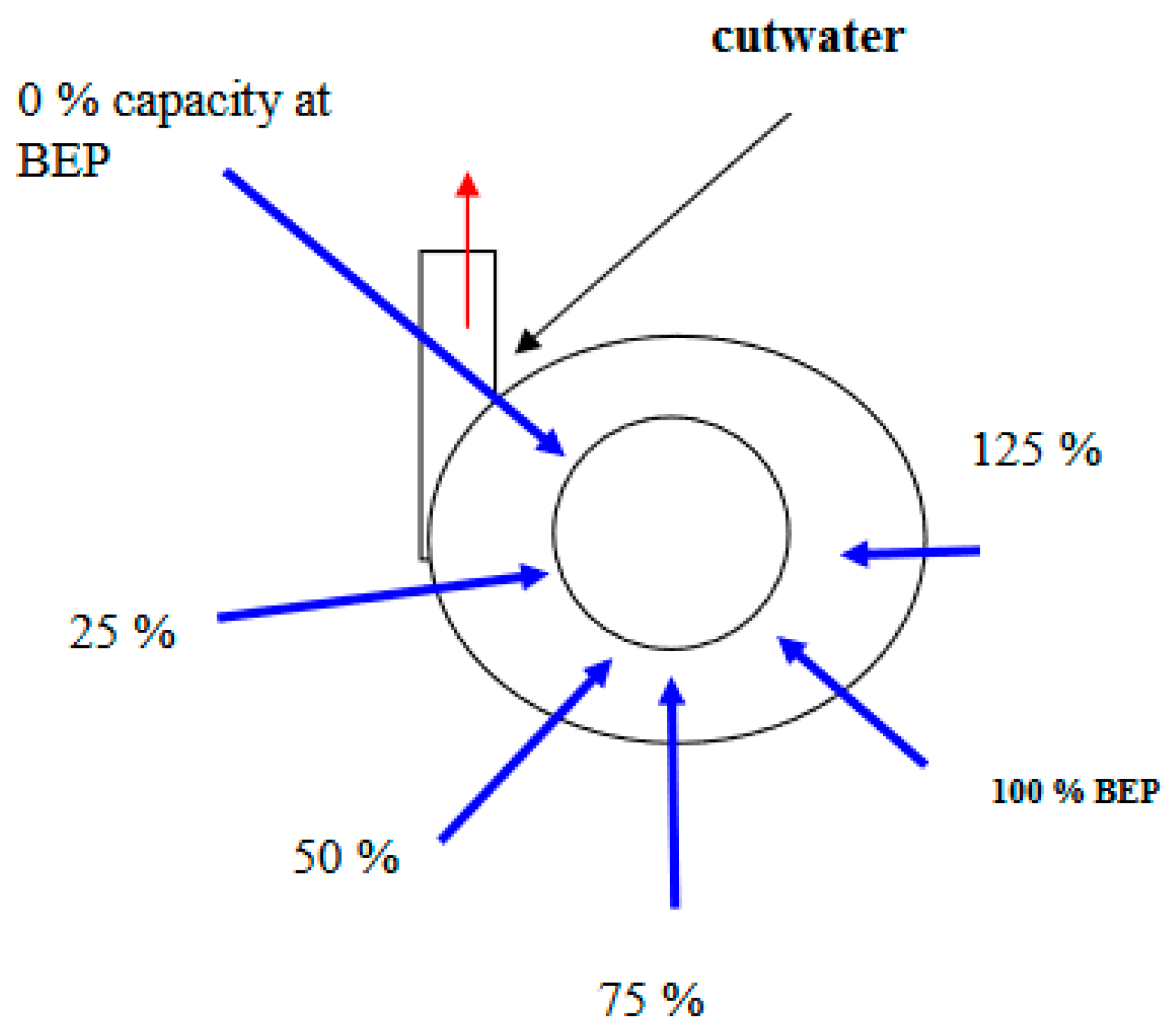
This force consists of radial and axial components, which together determine the rotor’s behavior and its stability level. As the flow rate decreases, radial loads increase; as the flow rate increases, the load decreases. Under nominal operating conditions, the flow is stable and the hydraulic force is minimal. The force vector moves along a spiral path in the direction opposite to the shaft rotation.
Figure 6 presents the distribution scheme of the radial static load and a graph showing the dependence of the force on the flow rate.
For approximate calculation of the radial force, the following relationship is used [
39].
where
Kr is the radial force coefficient (
Kr = 0.36);
D2—impeller outlet diameter, m; b
2—impeller outlet width,
m; ρ—fluid density, kg/m
3;
g—gravitational acceleration, m/s
2;
H—current head,
m.
For the dynamic rotor model, the flow pulsation effect is considered. It is determined by the following formula:
Formula for the pulsation of the radial force:
where:
Fr(t)—instantaneous value of the radial force, N;
Fr0—mean (static) value of the radial force, N;
ΔFr—amplitude of the pulsations, N;
f—pulsation frequency, Hz;
t—time, s.
The fundamental frequency of the radial force pulsation is related to the number of impeller blades and the rotor’s rotational speed. It is calculated by the following formula:
where:
f—pulsation frequency of the radial force, Hz;
Z—number of impeller blades;
n—rotor rotational speed, revolutions per minute (rpm).
In the MBD rotor computational model, the force is introduced as a quantity:
In this study, the hydrodynamic effect of the fluid on the rotor was taken into account in a simplified form—as an external harmonic force defined by Equation (7). This approach is based on the assumption that, in most cases, the dominant part of the hydrodynamic excitation of the rotor is associated with the primary harmonic components of pressure, which arise from the interaction between the impeller and the flow, as well as from flow non-uniformities.
In the MBD rotor computer model, the force will be introduced as a parameter. To identify the effect of the radial hydraulic force component on rotor vibrations, simulations of rotor motion will be carried out under different flow rate conditions. The pump’s operating flow range varies from 0.5Q to 1.5Q, therefore it is necessary to determine the head and pressure for different flow rate scenarios. In industrial practice, these parameters are measured on a hydraulic test bench; in our case, these values were obtained from a finite element model of the impeller using the CFD software CRADLE/Sflow [
40].
The data on forces acting on the pump rotor system are presented in
Table 2.
2.4. Support Modeling
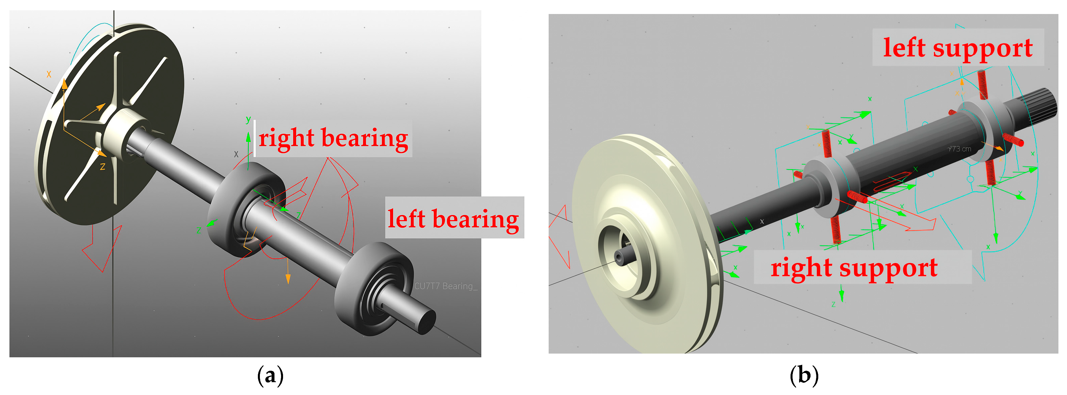
The ADAMS/MACHINERY software provides the capability to select bearings from a database based on the shaft diameter.
Figure 7a shows the kinematic rotor model with bearings chosen from this database. However, in our study, we employed the configuration presented in
Figure 7b. This spring-based modeling approach allows for multi-variant dynamic simulations of the rotor by varying the stiffness and damping properties of the rotor supports.
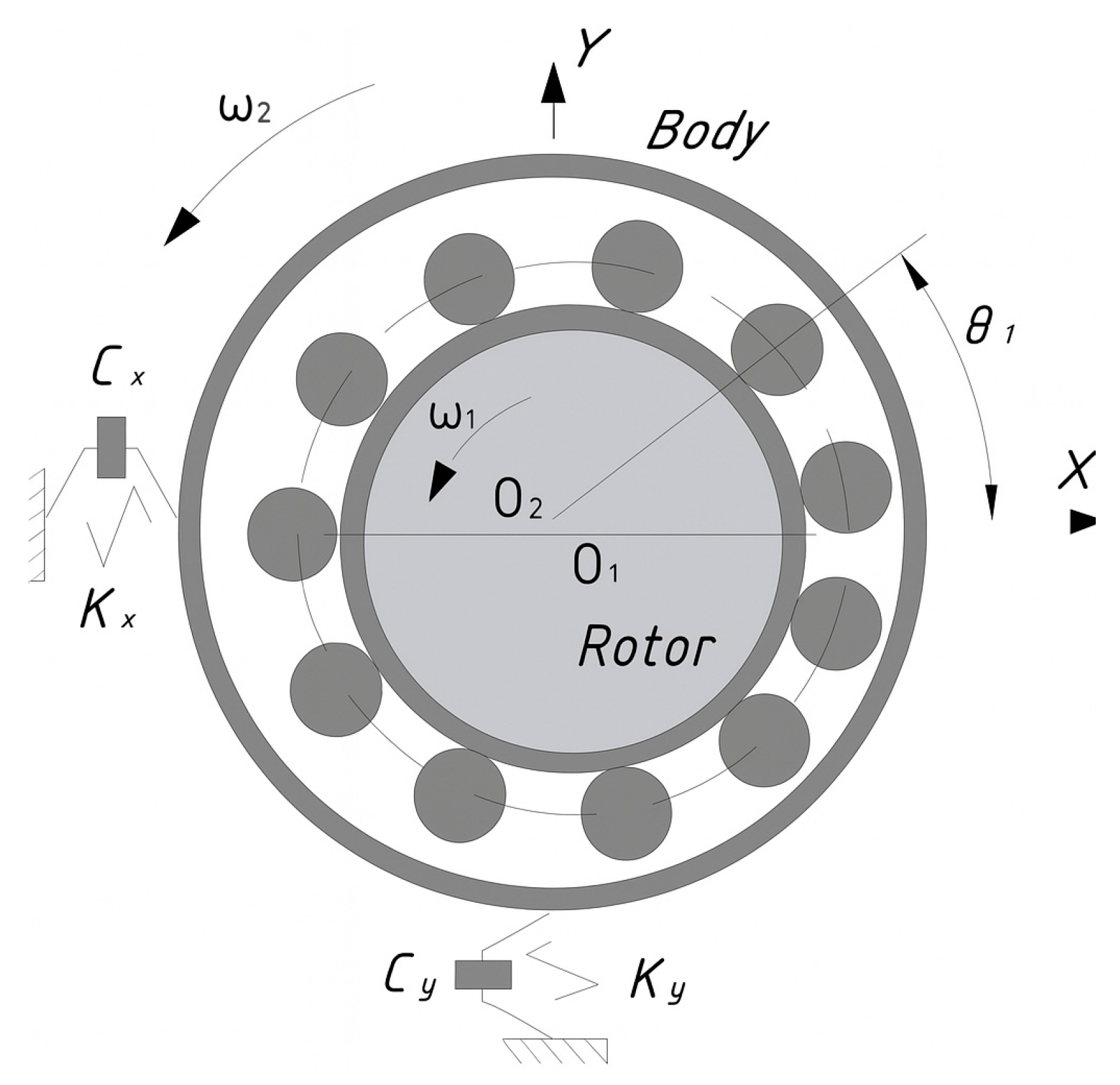
Rolling bearings in rotor system models are a crucial component, determining both the stiffness and damping characteristics of the support assembly as a whole (in the absence of elastic elements). To define the stiffness properties of bearings, various theoretical models are primarily used. The range of stiffness coefficients obtained from these models can vary significantly, which in turn leads to variation in the dynamic characteristics of the rotor system under study. The bearing model is illustrated in
Figure 8.
A simplified analytical approach to determining bearing stiffness is based on the assumption of a constant contact angle. This approach provides analytical formulas for calculating stiffness [
41].
In simple cases, engineers may use ready empirical formulas to determine radial stiffness coefficients. For example, the works by Harris and Kotzalas [
42] (“Rolling Bearing Analysis,” 5th Edition, Wiley, 2006) and Gargiulo [
43] present empirical formulas for estimating the radial stiffness coefficient of various bearings, assuming rigid rings.
For an angular contact ball bearing, the formula from [
43] is as follows:
Empirical stiffness formula:
where:
z—number of balls;
d—diameter of one ball.
To determine damping, Rao [
44] in
Mechanical Vibrations briefly addresses the topic of damping in rolling bearings. He states that both theoretical and experimental evaluation of this damping is very complex. Rao proposed an approximate formula for estimating the damping capacity of a rolling bearing:
where:
ζ—damping coefficient;
m—mass of the structure.
A value of ζ = 0.05 corresponds to moderate damping (approximately 10–20% of energy is lost per cycle) and is applied to rolling bearings, machine tool supports, and damping materials.
The geometric parameters of the bearing were determined using the ADAMS/MACHINERY module. The bearing parameters are presented in
Table 3.
2.5. Marker Creation
To measure vibrations, ADAMS allows the setup of measurement points linked to specific sensors or virtual markers on the object. In our model, markers were created on the support surfaces. The shaft’s center of mass marker was automatically generated when assigning the material density (steel) and was shifted by the eccentricity value. Additionally, four markers were associated with the springs. The constraints and forces are listed in
Table 4.
2.6. Assembly Calculation
Two rotor assemblies were created: the first using the built-in bearing database in the Adams Bearings Plugin (Machinery toolbox), and the second modeling the supports as elastic elements (“springs”) with specified stiffness and damping (
Figure 7). Preference was given to the second assembly option, as it allows multi-variant simulations by varying stiffness and damping to optimize the damper and adjust the vibration behavior. The main components of the model and their characteristics are as follows:
- 1.
Shaft: The shaft material is steel, as specified in the Adams material library. The steel’s Young’s modulus is 207 GPa, Poisson’s ratio is 0.29, and density is 7801 kg/m3. The shaft mass is m = 2.02 kg, with moments of inertia around the x, y, and z axes equal to Ixx = 1836.0672 kg·mm2, Iyy = 1823.5965 kg·mm2 and Izz = 2523.579 kg·mm2, respectively.
- 2.
Rigid Disc: The mass unbalance is created by a single rigid disc mounted on the flexible shaft. The disc mass is 1.99 kg, with moments of inertia around the x, y, and z axes equal to Ixx = 3180.0672 kg·mm2, Iyy = 3091.5965 kg·mm2, and Izz = 3086.579 kg·mm2, respectively.
- 3.
Bearings: The shaft is supported by two radial ball bearings. The bearings are modeled using the Adams Bearings Plugin (Machinery toolbox) with detailed representations that account for their stiffness, possible nonlinearities, and realistic contact conditions.
2.7. Kinematic Constraints
The Adams dynamic solver was preconfigured to use the Newmark integrator. The GSTIFF solver was also considered; however, although implicit solvers generally handle nonlinearities better than explicit ones, the Newmark method still outperforms purely implicit solvers in many cases, often enabling simulations to converge and find solutions where a solver like GSTIFF may struggle.
For the simulation, the “Motion” parameter was set. In ADAMS (MSC Adams), the “Motion” parameter is used to define the movement between two bodies—typically the relative displacement (e.g., rotation, linear translation) between bodies through a joint. This tool specifies how one body moves relative to another over time. According to ADAMS units, the angular velocity of 9000 degrees per second (or 1500 rpm) corresponds to the input speed of the electric motor.
It should be noted that the following assumptions were made in this study:
- 1.
The bearing type and dimensions supporting the rotor are identical;
- 2.
The gravitational effect is taken into account;
- 3.
The SRS model activation time is 2 s, with a time step size of 0.01.
2.8. Experimental Section
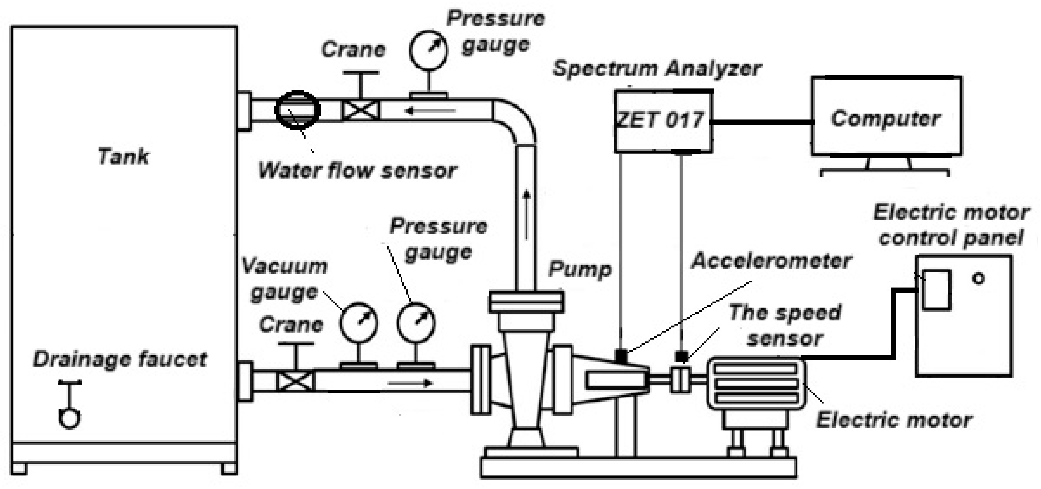
The experimental test rig consists of a centrifugal pump connected to an electric motor (Karlskrona Kazakhstan, model: CHP 32-160, 0.75 kW, 1500 rpm, 3-phase, 380 V, head 5 m, and flow rate 8 m
3/h), a control panel with a Nietz NZ2200-1r5g speed controller (
http://www.nietz.cn/English/Default.aspx, accessed on 10 August 2025) (a frequency-controlled drive with a speed regulator, ON/OFF switch, and emergency stop), a water flow meter model “CASCAD” WM-CW32 DN32 mm Class C, pressure gauges, a vacuum gauge, valves, and PVC pipes.
For collecting experimental data, a ZET 017-U2 spectrum analyzer (ZETLAB, Moscow, Russia) with 2 input channels and software by ZETLAB 2024 (
https://zetlab.com/) is used.
Sensors:
- 1.
Accelerometer BC 110 for vibration level measurement, with a sensitivity of 1000 mV/g and a frequency range from 3.4 to 18 kHz (±10%). (
https://zetlab.com/).
- 2.
Non-contact optical speed sensor ZET 402 for measuring angular velocity. Measurement range: 0 to 50,000 rpm. (
https://zetlab.com/).
- 3.
Microphone ZET 501 for measuring sound pressure levels, with a sensitivity of 100 mV/Pa and a frequency range of 50 Hz to 13 kHz. (
https://zetlab.com/).
Figure 9 and
Figure 10 show the schematic and the test rig for evaluating the performance of the centrifugal cantilever pump.
The experimental test rig for evaluating the centrifugal cantilever pump was designed and assembled at the U.A. Djoldasbekov Institute of Mechanical Engineering (IMMash).
To validate the computational results, triple repeated measurements of vibration characteristics were conducted under constant rotor operating conditions (100% of the nominal speed) to assess data repeatability. The number of repetitions was selected in the range of 3 to 9, in accordance with the recommendations of ISO 5725-2 [
45] and ASTM E691 [
46], which allows for reliable determination of the standard deviation and coefficient of variation. The duration of a single measurement cycle for each operating mode was no less than 30–60 s of stable system operation. The stability of the collected data was evaluated by calculating the coefficient of variation (CV) for each series of measurements using two installed sensors.
According to ISO 20816-1:2016 [
47], various vibration analysis methods use both peak and root mean square (RMS) values, while other authors apply their own criteria, such as the crest factor. For the verification of the numerical model in this study, a single measurement period was sufficient. The difference in the startup time between the experimental setup and the simulation is explained by the fact that, in the numerical model, the rotor acceleration time was limited to 2 s in order to reduce computational cost and to isolate the steady-state vibration regime. In contrast, in the physical experiment, acceleration lasted 4–9 s due to the influence of real inertial and resistive factors.
3. Discussion and Results
3.1. Verification of the Rotor Computer Model
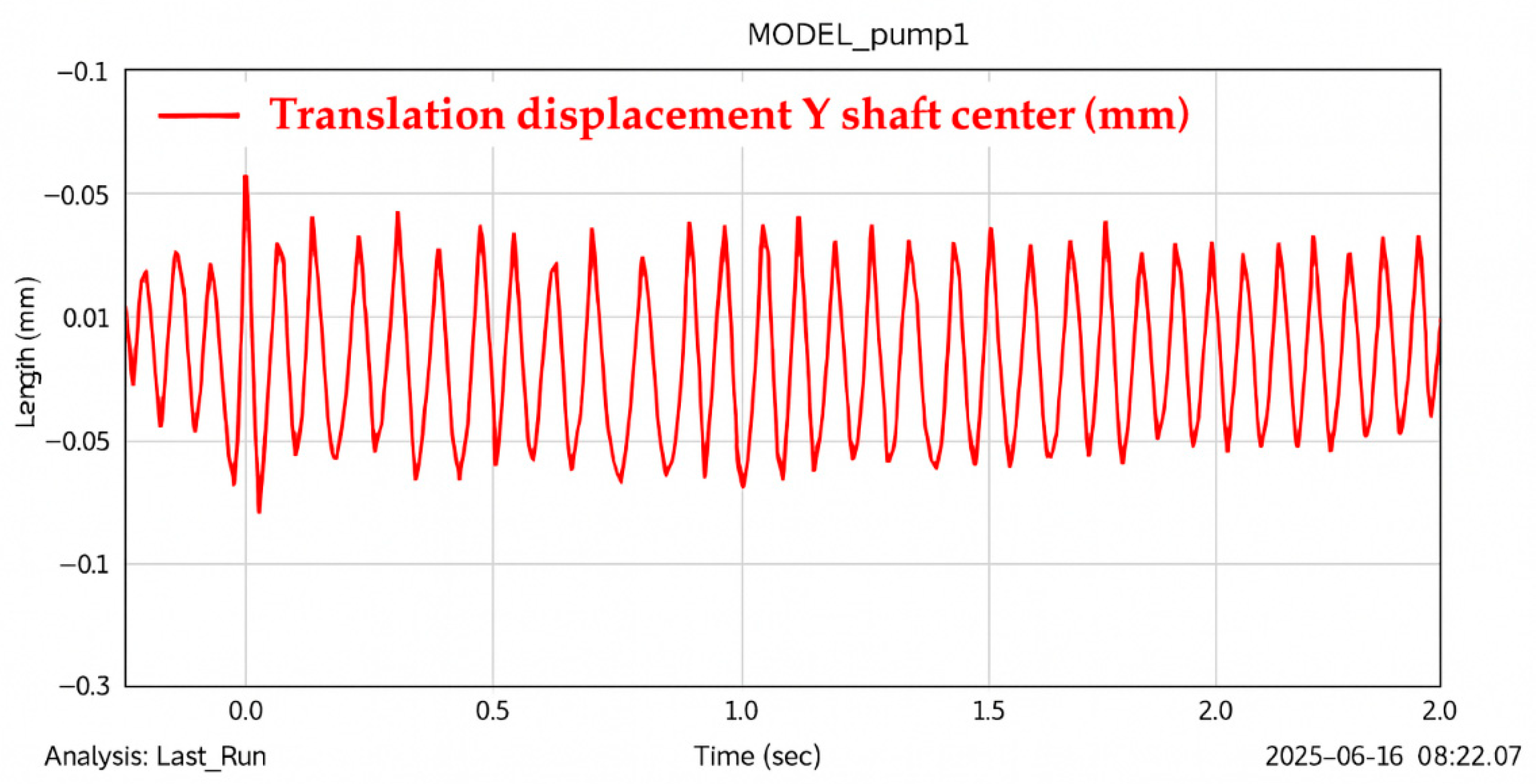
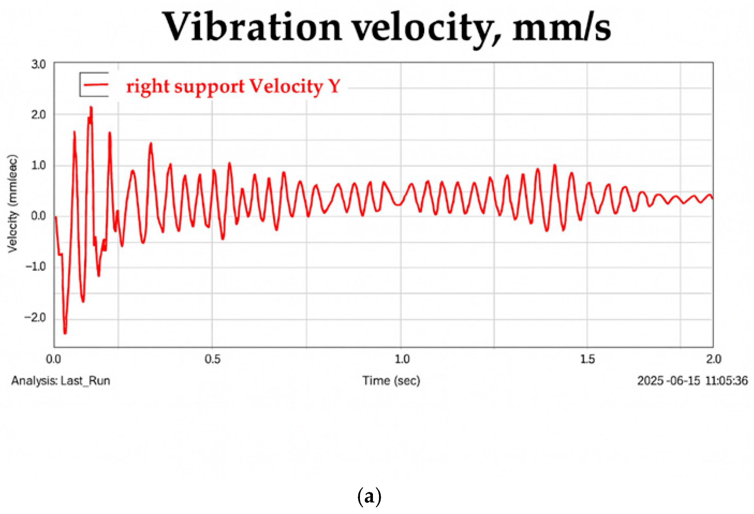
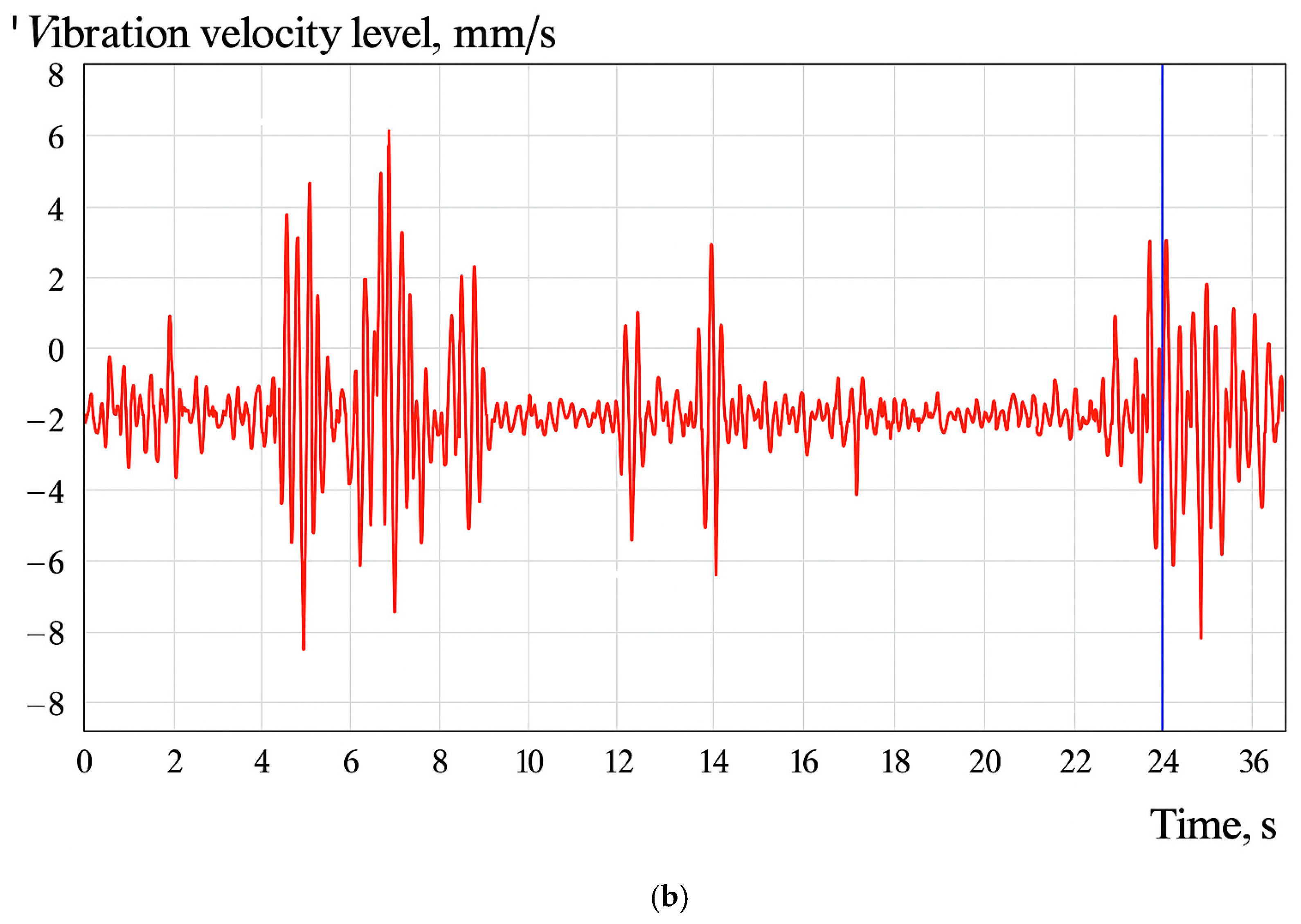
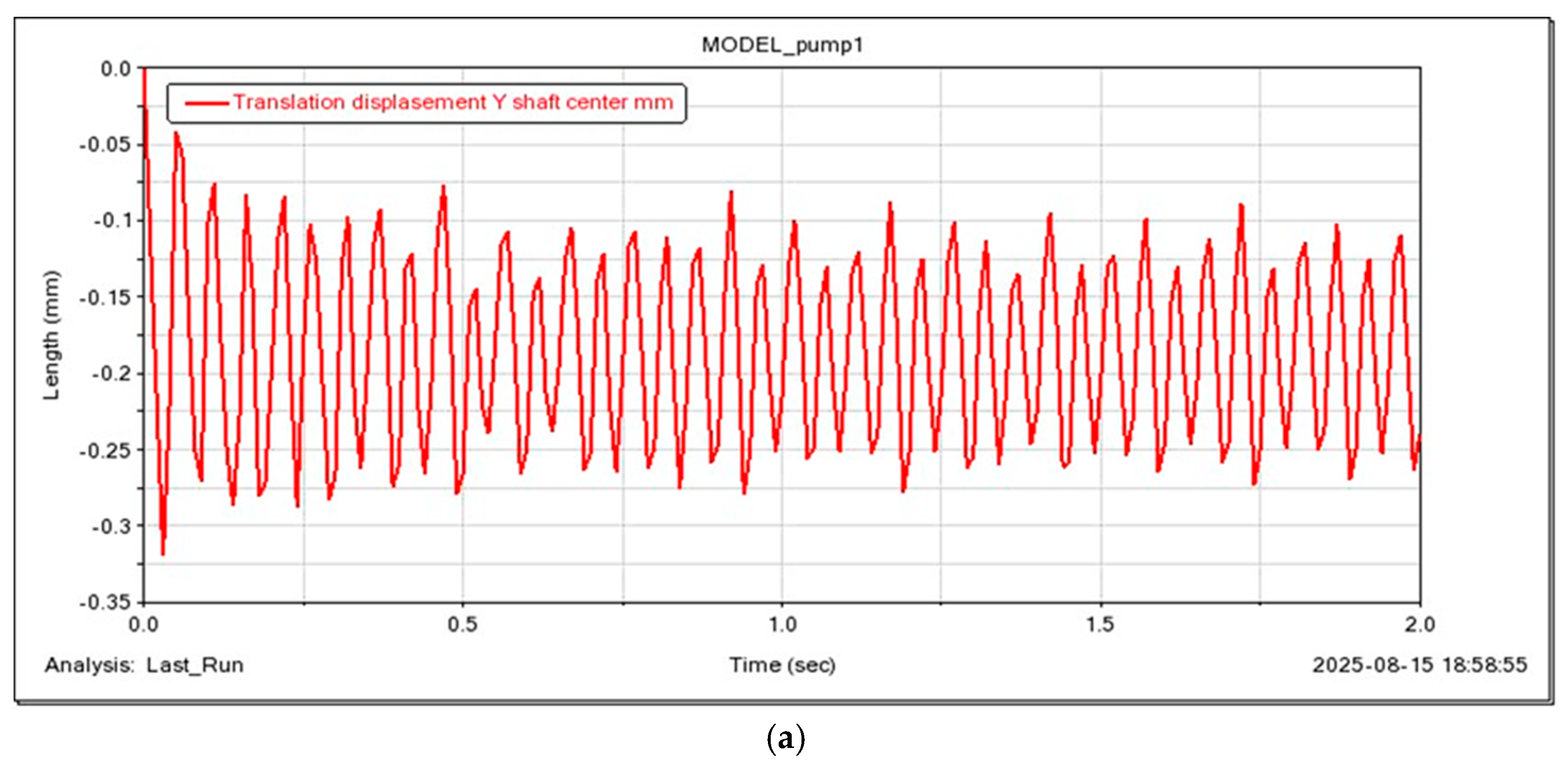
For the verification of the rotor computer model of the CHP 32-160 pump (KARLSKRONA, Shymkent, Kazakhstan), the results of experimental tests were compared with those of the computational experiment in ADAMS. The vibration results of the left and right support markers and the shaft’s center of mass are shown in
Figure 11,
Figure 12 and
Figure 13. According to the bearing velocity measurements, the right support generates significantly more disturbances than the left one, due to the asymmetric placement of the supports relative to the impeller and the cantilever design. In contrast, study [
48] described a different situation, where in a rotor with symmetrically placed supports, the bearing closer to the motor experienced greater disturbance from the motor torque. In the current rotor design, the right bearing (farther from the motor and closer to the impeller) experiences a greater influence from imbalance forces and hydraulic forces than the left bearing. Greater instability in the movement of the right support can be observed at startup: the peak velocity reaches 20.5 mm/s at the initial stage in the computational experiment and 11.5 mm/s at 4 s in the test rig, with a longer time required for stabilization of the right support’s motion. Meanwhile, the left support’s motion stabilizes more quickly, with a peak velocity of 6 mm/s. For the left support, the peak velocity is 20 mm/s at the start in the simulation and 9 mm/s at 9 s in the test rig. Although the peak values at startup differ, the overall vibration spectra and root mean square (RMS) values for the right bearing (5.7 mm/s) and the left bearing (3.4 mm/s) are close in both results. It should be noted that the discrepancy in peak values at the initial stage is explained by the absence of damping in the model from the coupling connecting the motor and rotor shafts. All vibrations and disturbances transmitted from the motor startup propagate directly to the bearings without energy loss due to friction, viscosity, plasticity, etc. However, the coupling always possesses some damping properties (even if rigid), which partially attenuate resonant and transient vibrations, reduce vibration amplitudes, and facilitate faster stabilization. The model without damping overestimates the “sharpness” of the system’s response to startup. The vibration spectrum of the center of mass shows a stable contour, indicating energy dissipation around the center of mass and energy absorption by the bearings.
Figure 12 and
Figure 13 show the vibration velocity graphs of the bearings for one of the three measurement series.
Table 5 presents the results of the measurement error analysis for the root mean square (RMS) values of the vibration velocity at the left and right bearings.
The quantitative assessment of rotor vibration was performed using RMS values. The RMS values were calculated with non-uniform time steps, following the methodology described below:
where
T—total observation time;
ti—time intervals at discrete segments;
Vi—vibration velocity amplitude values.
According to ISO 20816-3:2022 [
49], for engineering vibration measurements or dynamic testing of machinery, a coefficient of variation (CV) below 10% is generally considered a good indicator of data stability. In practice, efforts are often made to achieve CV values in the range of approximately 3–7%. The root mean square (RMS) vibration velocity values obtained from the computational experiment were 8.6 mm/s for the right bearing and 2.9 mm/s for the left bearing. The difference in RMS values between simulation and experiment was 36% for the right support and 38% for the left support.
The discrepancy between numerical and experimental measurements can be explained by several factors. Firstly, in the numerical model, rotor system vibrations are attributed solely to hydraulic excitation. However, during practical operation, other sources of vibration inevitably arise due to mechanical processing and assembly, such as external forces caused by mass imbalance of the impeller, rotor asymmetry, and the electric motor. Secondly, the approximate computational model cannot directly provide information about bearing vibrations due to model limitations related to other factors damping the oscillations. Instead, bearing vibration is approximately reflected by the data measured at the shaft node connected to the bearing. Due to the high stiffness of the bearing, the measured vibration velocity values are lower than the simulated results, and the experimental data exhibit the presence of multiple harmonic components. Despite these discrepancies, the deviations are within an acceptable range for engineering applications. Accordingly, the model demonstrates sufficient accuracy and reliability for use in further rotor shaft vibration analyses.
3.2. Effect of Rotational Speed on Transverse Vibration
The change in motor rotational speed directly affects the vibration characteristics of the SRS.
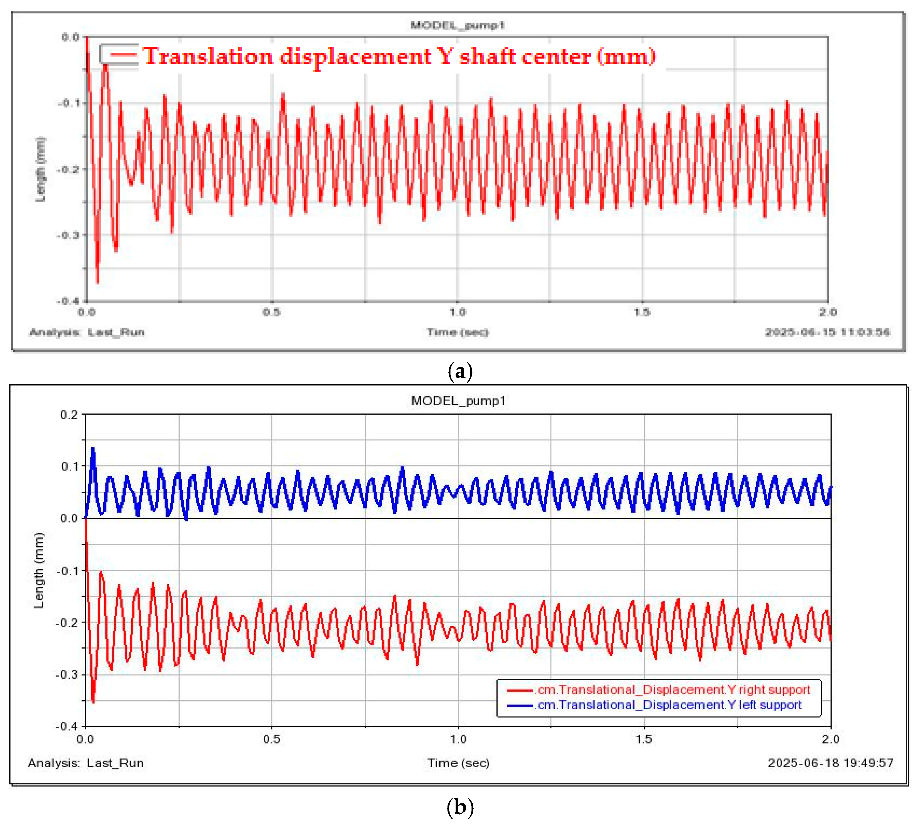
Figure 14,
Figure 15,
Figure 16 and
Figure 17 show the transverse vibrations of the pump shaft, the left bearing, and the right bearing, respectively, which vary over time. It can be observed that at low motor speed (600 rpm), the signal waveform is chaotic in the initial region around 0.5 s, and the transverse vibration fluctuates unstably, as shown in
Figure 14a. As the motor speed increases, the transverse vibration and signal waveform become more stable.
In the present study, the shaft rotation frequency range is considered only up to the nominal value, which is significantly lower than the potential critical speeds. Within this range, an increase in rotational speed indeed contributes to enhanced system stability due to the growth of centrifugal forces and increased rotor stiffness. However, with further increases beyond the nominal rotational speed, system stability may decrease as a result of dynamic effects such as the excitation of resonant vibrations and the approach to critical speeds.
When comparing parameters such as bearing type, operating rotational speed, and rotor design adopted in this study with those reported in the literature, these results are consistent with the modeling outcomes obtained by Liu et al. [
50], which to some extent confirms the accuracy of the current simulation. Thus, it is evident that transverse vibration of the shaft is higher than the sidewise transverse vibration measured at both the left and the right bearing locations, indicating that the shaft is flexible.
To investigate the influence of motor rotational speed on dynamic characteristics, the displacement amplitudes of the shaft vibrations and those of the left and right bearings were measured for vibration analysis.
Figure 14,
Figure 15,
Figure 16 and
Figure 17 present the amplitude of the flexible shaft vibrations, in centimeters, as a function of the motor rotational speed. The lines represent the maximum and minimum response values of the system displacement along the
Y-axis at various speeds. It is observed that due to the gravitational effect on the rotor (flexible shaft), the shaft center is positioned downward in the vertical direction. High vibration amplitudes were recorded at rotational speeds of 600 and 900 rpm. It was also noted that the displacement amplitude of the left bearing is smaller than that of the right bearing, which is associated with the left bearing being located farther from the impeller and closer to the motor, which acts as an additional support with its own dynamic stiffness and damping characteristics.
3.3. Influence of Installed Eccentricity on the Transverse Vibration of the Shaft
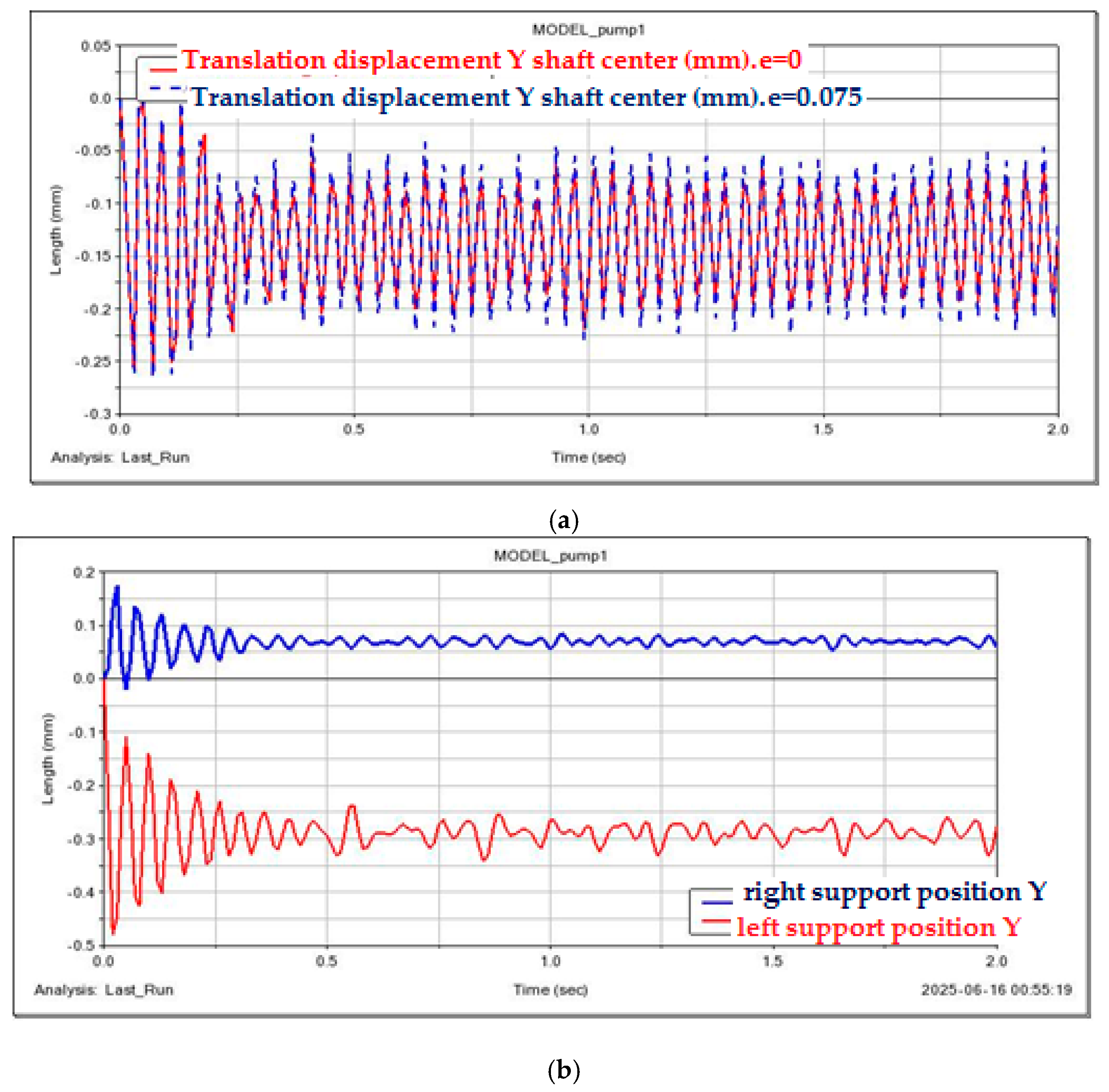
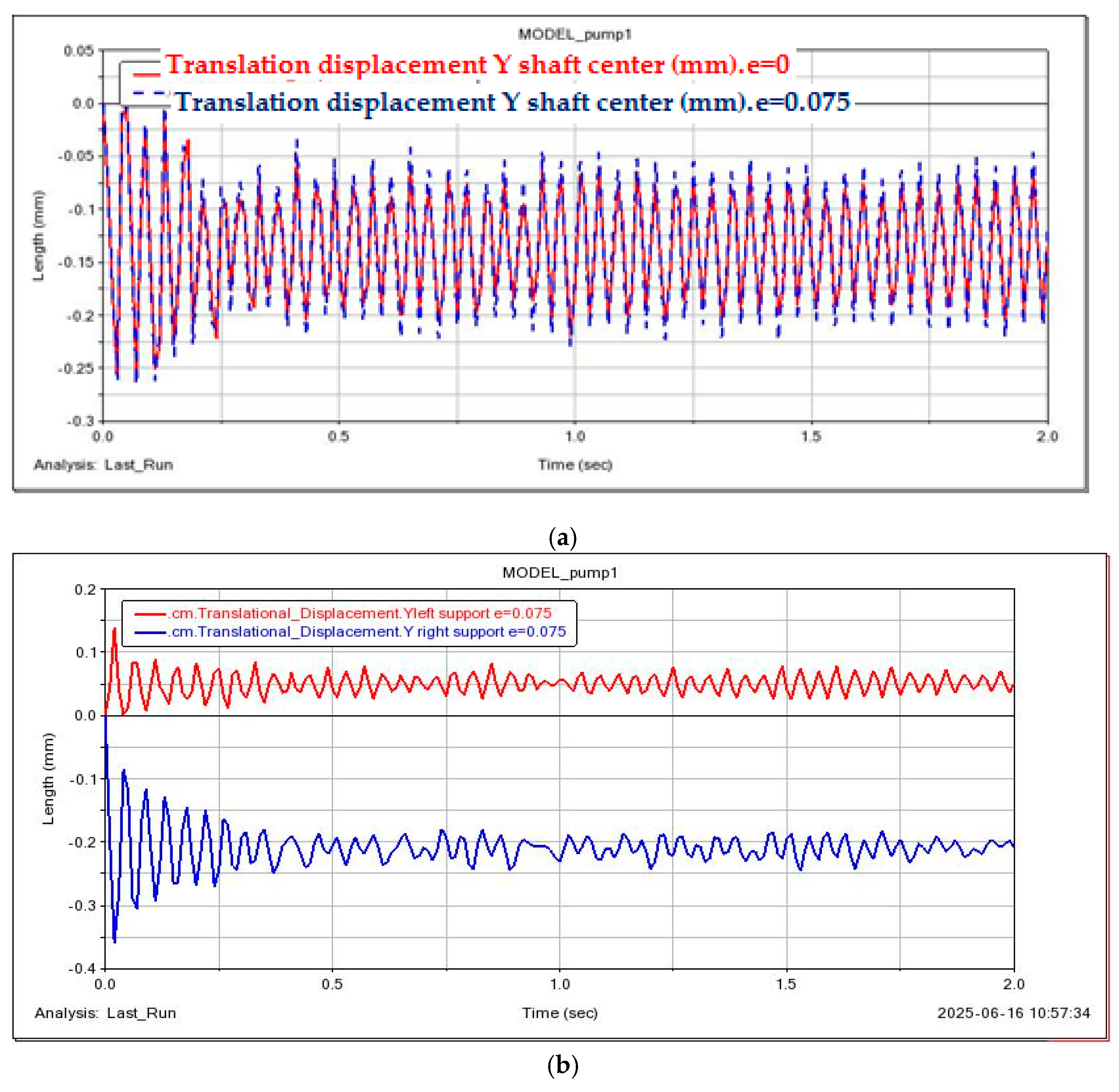
To study its effect on the transverse vibration at the disk, simulations were performed for the case with the center of mass coordinates determined automatically by the program, and for the case where the center of mass was shifted along the
Z-axis by 0.075 mm, as indicated in
Table 1.
Figure 18 show the vibration diagrams of the shaft’s center of mass marker with eccentricity and the bearings. It can be observed that the shaft vibration diagram practically did not change, as did the vibration diagrams of the shaft bearing centers of mass (compare
Figure 14b and
Figure 18).
Zhou et al. [
51] investigated three different eccentricity values—0.1, 0.2, and 0.3 mm. However, this approach is not applicable to the present study, as the impeller diameter is 170 mm (i.e., less than 300 mm), and the corresponding eccentricities are relatively small and have negligible influence on the system’s dynamic response.
3.4. Approximate Models for Determining Dynamic Characteristics of Dampers
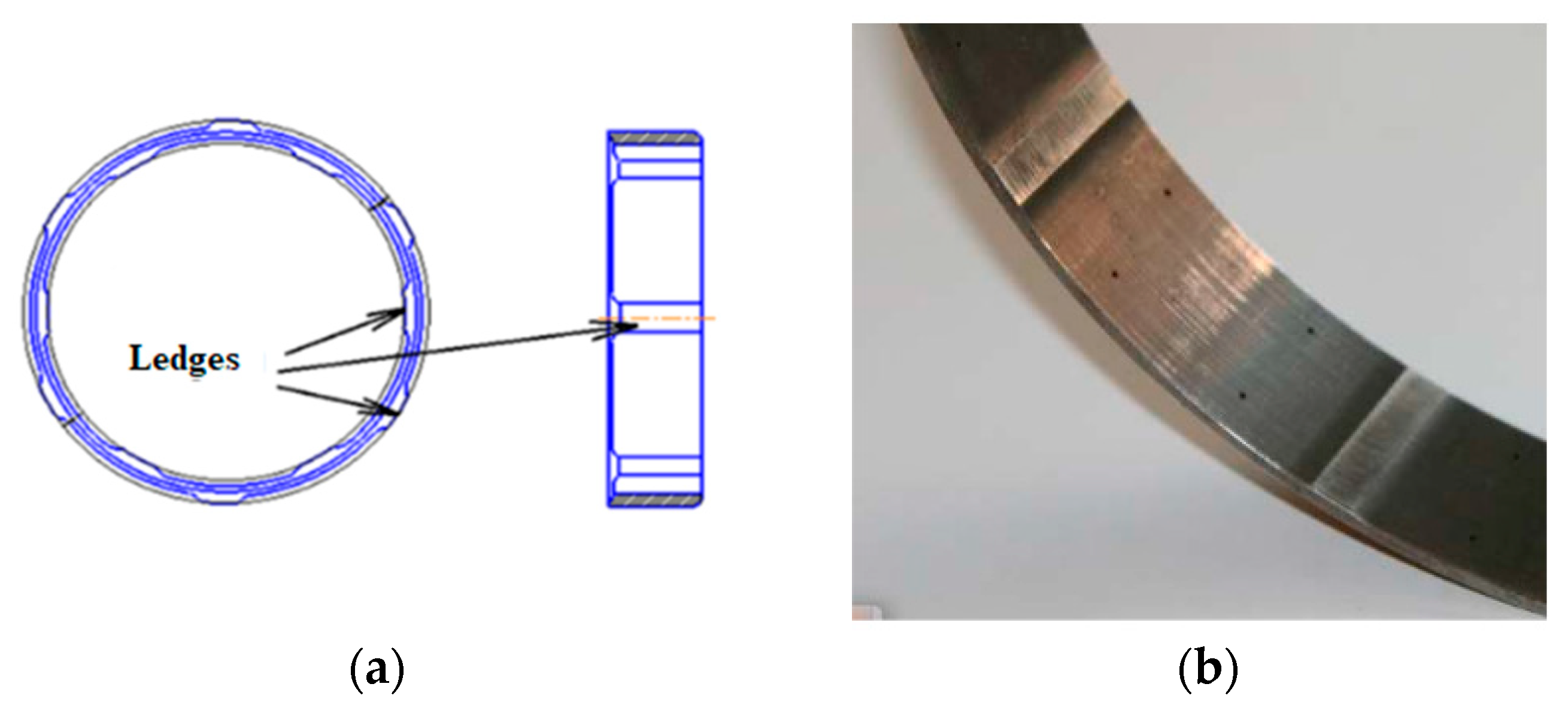
To reduce the amplitude of vibrations occurring in rotors, various damping devices are used, which are installed at the bearing supports. One of the simplest yet effective types of such devices is the damper with elastic rings. The design of this damper includes a single elastic element (in some cases two), which is a thin-walled ring with smooth protrusions evenly distributed around its circumference, both inside and outside. The protrusions are arranged in a staggered pattern, as shown in
Figure 19. The elastic ring is typically mounted over the outer race of rolling bearings. Various design options were also considered, including the use of rubber or polymer inserts, hydraulic (oil-based) dampers, and combined elastic-damping units. However, rubber and polymer dampers are unreliable under the operating temperatures and rotational speeds characteristic of this rotor due to their limited service life, material aging, and susceptibility to cracking. Hydraulic dampers and active systems, in turn, require more complex designs and maintenance, which is economically unjustified for this class of machinery.
The design and main dimensions specified in OST 1 14724-90 are of a recommendatory nature and can be adjusted based on the required values of ring stiffness, damping, as well as static and dynamic stresses occurring during operation.
The advantages of damper supports with elastic rings include compact size and low weight; linear stiffness characteristics; rotor centering relative to the motor shaft; high damping properties (comparable to those of labyrinth-type hydrodynamic dampers); and the presence of an industry standard for elastic rings, which facilitates the selection of initial ring dimensions, as well as the calculation of compliance and strength. Among the disadvantages are the necessity to ensure high manufacturing accuracy of all dimensions and fitting locations, and the lack of simple mathematical models for accurately predicting the damping capacity [
52].
The aim of the present work is to select and determine the damping coefficient of such a device using the developed multibody dynamics (MBD) model. The built-in bearing models with springs will enable us to address this task effectively.
The calculation of the optimal stiffness of the damping ring in the rotor support is a task of coordinating the stiffness and damping parameters of the “rotor—bearing—ring—housing” system to: reduce vibrations, improve rotational stability, and provide sufficient compliance and damping while maintaining strength and service life.
In the calculations, we used a simplified two-mass model, in which the bearing and the ring are connected in series, and the stiffness and damping of the assembly are determined by the following formulas [
53]:
where:
is the equivalent stiffness of the system,
is the stiffness of the bearing, and
is the stiffness of the ring. In practice, the optimal ring stiffness is generally considered to be:
The coefficient in formula (12) varied in the specified range and with repeated computational experiments, it was concluded that the most optimal stiffness, damping of the support unit and the oscillation parameters of the rotor will be at the parameters:
The required ring stiffness is ;
Ring damping is determined by the following Equation (3) ;
The equivalent stiffness of the bearing assembly is ;
The equivalent damping of the bearing assembly is .
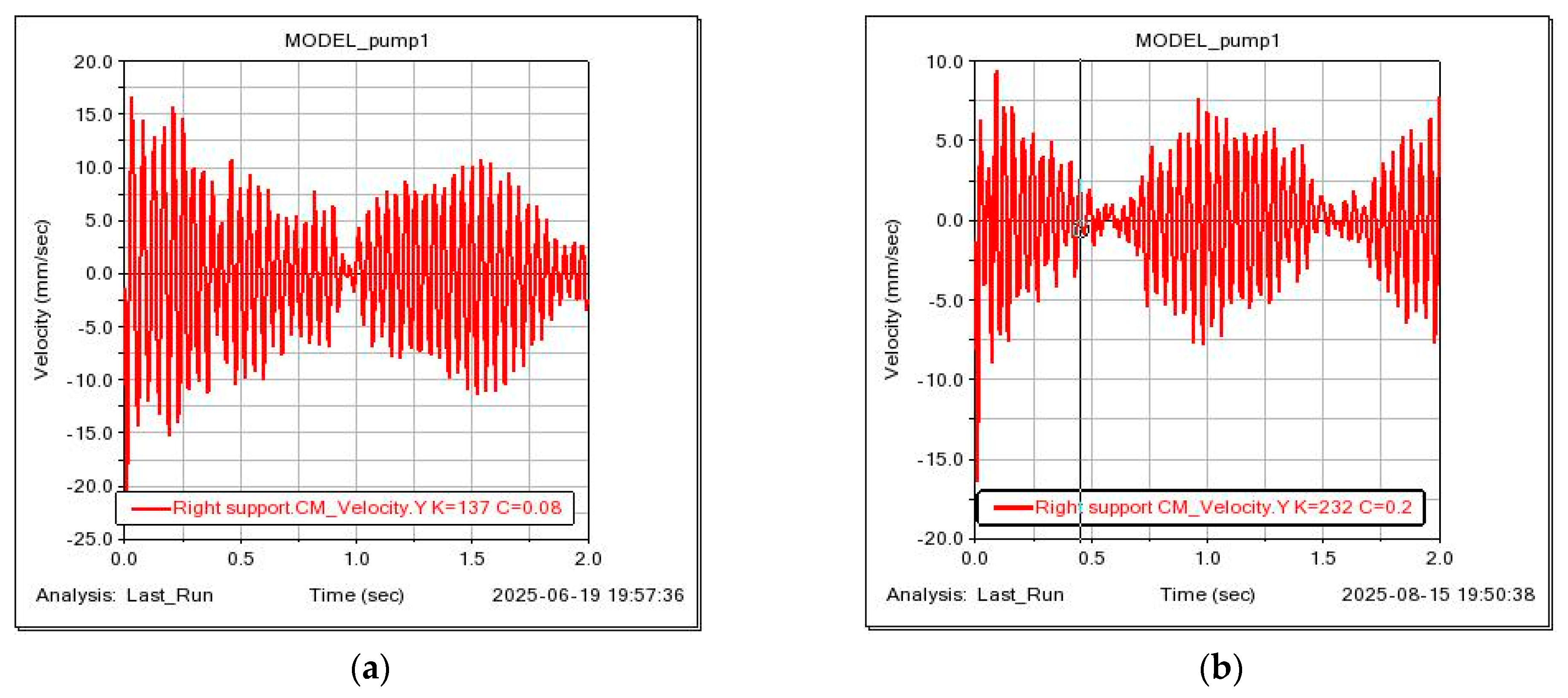
Figure 20 presents a comparative displacement diagram of the marker located at the rotor shaft’s center of mass under different configurations of support stiffness and damping. The first case corresponds to the initial conditions of
Kb = 137 N/mm,
Cb = 0.08 N
s/mm; the second case includes the addition of an elastic steel ring, resulting in modified parameters of
Kb = 232 N/mm,
Cb = 0.18 N
s/mm.
Figure 21 shows the vibration acceleration diagram for the shaft’s left and right support units.
Analysis of the displacement diagram in
Figure 18 for the marker at the rotor shaft’s center of mass indicates that the shaft deflections shifted upwards following the introduction of the elastic ring into the support structure. Additionally, the amplitude of the center of mass vibrations decreased. The vibration velocity diagrams of the shaft supports clearly show that the peak vibration velocities at the left support decreased from 20 mm/s to 7 mm/s at the inlet, while the peaks at the right support reduced from 16 mm/s to 10 mm/s. The overall vibration amplitude range for both supports was also diminished.
4. Discussion
The sequential analysis presented above demonstrates that the proposed mechanical calculation scheme and MBD (multibody dynamics) method are applicable for predictive modeling of centrifugal pump rotor behavior. The developed model was aimed at more accurately accounting for the elastic-damping properties of the rotor supports. Model validation was carried out using the results of physical experiments. The observed discrepancies (up to 38%) are mainly due to the application of the classical Jeffcott rotor model, which does not fully capture the actual operating conditions of the rotor within the unit. In particular, coupling elements such as the motor and flexible coupling were not included in the model, which significantly affects the simulation results.
Furthermore, deviations were introduced by modeling the bearings as linear elastic-damping elements with constant stiffness and damping. In reality, especially for hydrodynamic bearings, their behavior is nonlinear. Future research will expand the model’s boundary conditions to incorporate nonlinear bearing characteristics, temperature-dependent changes in lubricant film properties, and gyroscopic effects at high rotational speeds.
The study of the influence of motor rotation frequency on the rotor’s dynamic characteristics revealed that higher vibration peaks occur at lower rotational speeds. This is explained by the fact that at low speeds, vibrations caused by external factors (e.g., imbalance, impacts, misalignment) are not “averaged out” by the system dynamics. At higher speeds, the rotor stabilizes along a well-defined rotational path, while at lower speeds, even minor shocks or eccentricities are immediately reflected in transverse vibrations.
Numerous experimental data and practical observations confirm the significant influence of residual unbalance on the vibration levels of centrifugal pump rotors at the operating frequency of the impeller. In practice, this has led to increasingly stringent requirements on permissible unbalance, along with tighter manufacturing and machining tolerances, thereby increasing production costs. However, this does not always lead to a noticeable reduction in vibration levels. The computational modeling of the rotor-impeller system dynamics conducted in this study supports the theory proposed by a large body of researchers [
54], who argue against attributing a dominant or even significant role to residual unbalance in the generation of high vibration activity or its influence on centrifugal pump rotor dynamics.
The results of this study demonstrate that when the impeller diameter of the pump is less than 300 mm, eccentricity has an insignificant effect on rotor vibrations. This conclusion is supported by the comparative diagrams presented in
Figure 12 and
Figure 15. Overall, this statement is justified: from a mechanical standpoint, the contribution of unbalance forces to the equation of motion remains below the sensitivity threshold of the system. According to ISO 21940-11:2016 [
55] (G6.3–G2.5), the threshold criterion can be expressed as the ratio of radial eccentricity e to the outer diameter D of the impeller. When e/D < 0.0002–0.0003, the influence of unbalance remains negligible and does not exceed the permissible vibration limits.
In combination with elastic elements such as a flexible ring possessing a certain stiffness, such a support unit can partially relieve the rotor from static and dynamic loads, while maintaining a constant overall stiffness for the support.
Despite the discrepancies observed during the verification of the computational and physical models of the pump rotor, we consider the proposed model to be justified and applicable for further analysis of rotor system vibrations and for the selection of integrated damping elements.
