1. Introduction
A progressive incremental inelastic deformation or strain that can occur in a component subjected to variations of mechanical stress, thermal stress, or both (thermal stress ratcheting is partly or wholly caused by thermal stress) is called ratcheting [
1,
2].
In order to prevent ratcheting failure, many scholars have studied its generation mechanism and control theory. The engineering evaluation chart for the shakedown design of pressure pipes or pressure vessels was proposed for the first time by Miller D. R. [
3] in 1959. In his study, an elastic–perfectly plastic thin-walled cylinder under internal pressure and alternating temperature gradient along the wall thickness was simplified into a uniaxial beam model in order to determine the critical conditions of thermal ratcheting deformation. In 1967, the mechanism of thermal stress ratcheting deformation was further stated by Bree J. [
4,
5]. Based on the theoretical formula of the shakedown limit load for a thin-walled cylinder under cyclic thermal–mechanical loads, the famous Bree diagram was established, which was the theoretical basis for thermal stress ratcheting assessment applied to design by elastic stress analysis. In 2005, A. Kalnins [
6] presented an example of a cylinder with an axial thermal strain gradient and pressure by using elastic–plastic ratchet analysis at the ASME Subgroup Design Analysis Meeting, whose results showed that the thermal stress range of ratcheting could meet the requirement of the Bree diagram but could not satisfy the assessment of elastic–plastic analysis. This led to many scholars’ research on the nonconservativeness of the Bree diagram. In view of the influence of thermal membrane stress, a three-dimensional ratcheting boundary by using the noncyclic method was deduced by Reinhardt W [
7,
8,
9]. He pointed out that Bree’s ratcheting boundary and the 3S criterion were unconservative when there is a significant thermal membrane stress, and the restriction of the thermal membrane stress should be supplemented. After some simplification of his analytical solution, this three-dimensional ratcheting boundary was adopted by the ASME VIII-2 2013 [
10] edition.
Since the ASME VIII-2 2007 [
11] edition, the heading of the clause “thermal stress ratchet in shell” was changed to “Thermal Stress Ratcheting Assessment”, and “maximum general membrane stress due to pressure” was changed to “the primary membrane stress”. These two changes indicate that thermal stress ratcheting assessment is not only applicable for the shell but also can be used for various symmetrical structures. In other words, the protection against thermal stress ratcheting failure not only involves the cylinder without structural discontinuity but also includes the effects of gross structural discontinuities, such as the junction of the shell and elliptical head, and the effects of local structural discontinuities (stress concentrations) are not included.
Meanwhile, primary membrane stress can also be induced by mechanical loads other than pressure, and it can be either global or local. Actually, the ratcheting evaluation clauses before the ASME VIII-2 2011 [
12] edition were based on the Bree diagram, in which only mechanical membrane stress and thermal bending stress are considered. The studies on the classical Bree problem, a series of subsequent modified Bree problems [
13,
14,
15,
16] and new ratcheting life prediction methods [
17,
18,
19], usually only involve these two stress parameters. As stated above, the restriction of thermal membrane stress was added in the ASME VIII-2 2013 edition in order to solve the nonconservativeness in the case of high thermal membrane stress. A new four-dimensional ratcheting boundary was derived by Shen et al. [
20,
21] under the interactions of four types of stresses, and constant mechanical bending stress was supplemented compared with Reinhardt’s original 3D ratcheting boundary. However, the influence of secondary stress has not yet been considered.
The 3S criterion based on elastic analysis in ASME VIII-2 has been extremely popular with engineering circles over the past 50 years due to its simplicity and convenience. However, it is unconservative to apply the 3S criterion for elastic ratcheting assessment when local primary membrane stress
exists (whose allowable limit exceeds (2/3) Sy). A more detailed introduction is provided in Reference [
22]. Reinhardt W. [
7] performed a numerical investigation on a cylinder with axial thermal discontinuities and found that the ratchet boundary stress level at discontinuities could be locally more than twice as high as that for uniform stress. This would create a high level of conservatism in the ASME Code analysis in most cases. In his study, thermal stress was separated from other discontinuity effects, and thermal stress instead of thermal bending stress would be excluded altogether from the 3S check if the 3S criterion is exceeded, which can remove some of the conservatism near discontinuities. However, in addition to thermal stress, secondary stress can also be caused by structural discontinuity effects under pressure load, and all secondary stresses that do not entail significant elastic follow-up are considered to have the same effect on structural behavior. Secondary stress due to structural discontinuity can cause ratcheting only at a much higher level of load than a uniformly distributed cyclic secondary stress field would, therefore, high enough conservatism still exists at a discontinuity.
Generally, local primary membrane equivalent stress at gross structural discontinuities not only includes general primary membrane stress but also a part of the secondary mechanical membrane stress . cannot be considered separately and explicitly in the current Code. It is always treated as a part of primary membrane stress, which is overly restrictive and will lead to a restricted application range of primary membrane stress.
In this paper, is separated from based on some assumptions and the relationships between the modified 3S criterion and the modified ratcheting boundary are discussed in detail. Then, two complete and feasible elastic ratcheting assessment methods considering based on the modified elastic shakedown boundary are proposed.
For thermal stress ratcheting assessment, two simplified elastic stress ratcheting assessment methods are also presented in this paper. They are based on the simplified approximate ratcheting boundary that considers the partition, so the assessment of is not required. Only one governing equation is involved, which is conservative and easy to apply.
Finally, a universal method of elastic stress ratcheting assessment considering is proposed to integrate the elastic ratcheting analysis, the thermal stress ratcheting assessment, and the simplified elastic–plastic analysis in ASME VIII-2. The proposed single-equation fitting eliminates the need for segmented verification and has engineering practicability.
2. Definition of and QL
The definition of local primary membrane stress in ASME Codes is as follows: Cases arise in which membrane stress caused by pressure, or other mechanical loading associated with a primary and/or discontinuity effect, would, if not limited, produce excessive distortion in the transfer of load to other portions of the structure. Conservativeness requires that such stress should be classified as local primary membrane stress even though it has some characteristics of secondary stress.
Based on the definition above, the following basic assumptions are made in this paper.
- (a)
= + ;
- (b)
= ( − 0) + ( − 0) +;
- (c)
is independent of ;
- (d)
= .
Assumption (a) considers that consists of and , thereby separating the effects of .
Assumption (b) is the consideration of the primary plus secondary stress range, where is induced by pressure and other mechanical loads at gross structural discontinuities. And and are both zero when shutdown occurs.
Assumption (c) considers as independent of the thermal bending stress range . is usually caused by constant internal pressure, while is induced by cyclic thermal loading.
Assumption (d) assumes that
can be decomposed into a constant stress
and a fully reversed cyclic part with amplitude
in order to derive a new ratcheting boundary considering
using the noncyclic method [
23,
24,
25].
4. Elastic Ratcheting Assessment Method Considering
In the case of local primary membrane equivalent stress PL, if ≤ 0.67, the 3S criterion is conservative enough to protect against ratcheting when using elastic ratcheting analysis. But when > 0.67, ratcheting failure may occur even if the 3S criterion is satisfied, and additional assessment criteria should be used.
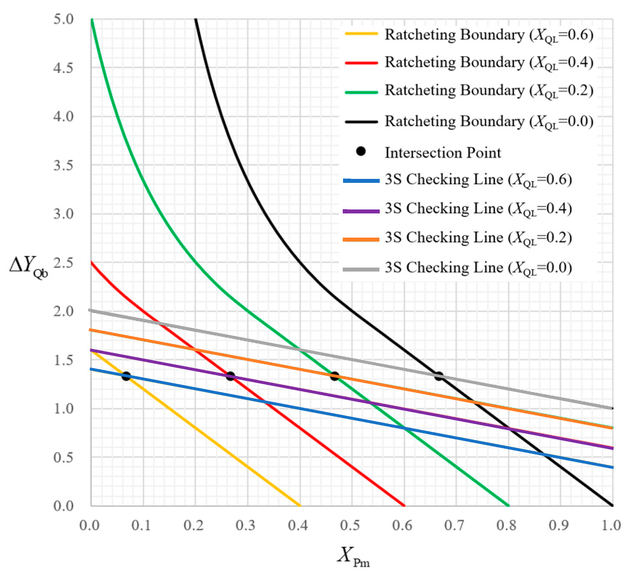
When is considered in elastic ratcheting assessment, the allowable limit of Pm can be obtained by solving the intersection coordinate of the modified 3S line and the modified Bree ratcheting boundary.
4.1. Method 1 ( = 0)
If
, it means that all the stress components classified as
are treated as
, i.e.,
. To satisfy the 3S criterion,
shall not exceed 2/3, that is,
Once exceeds 2/3, the structure should be redesigned or the applied load should be adjusted. Actually, Method 1 is the requirement of the 3S criterion adopted by the current ASME Code. This method is highly conservative since may exceed (2/3), to the maximum , and also because the secondary mechanical membrane stress is entirely treated as primary membrane stress. Therefore, a complete and safe elastic ratcheting evaluation method based on the intact elastic shakedown boundary can be given in the whole domain of , and the secondary stress can be separated from the primary membrane stress.
4.2. Method 2 ( 0)
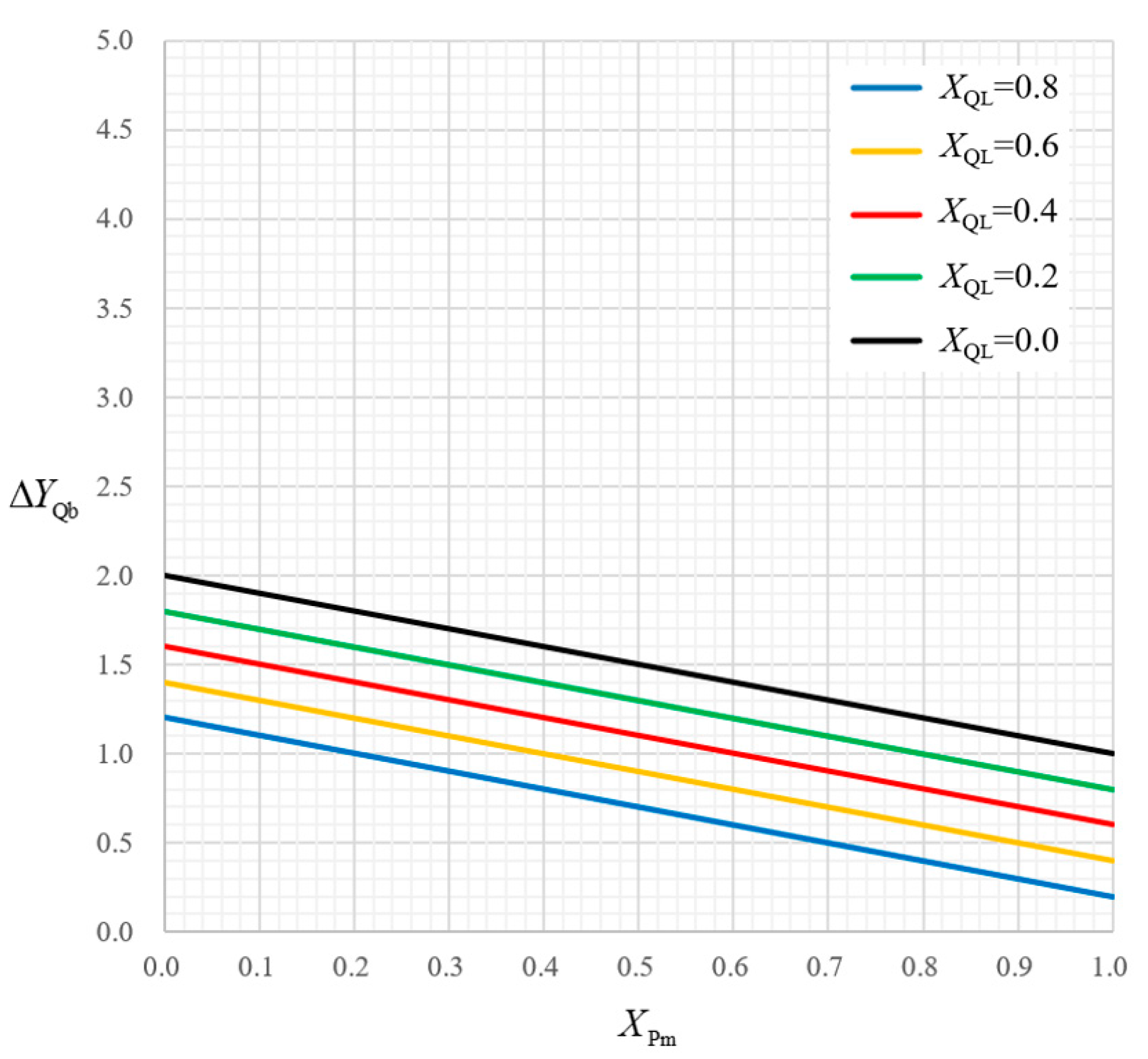
Two alternatives are proposed here based on the two kinds of modified Bree ratcheting boundaries and the modified 3S lines considering .
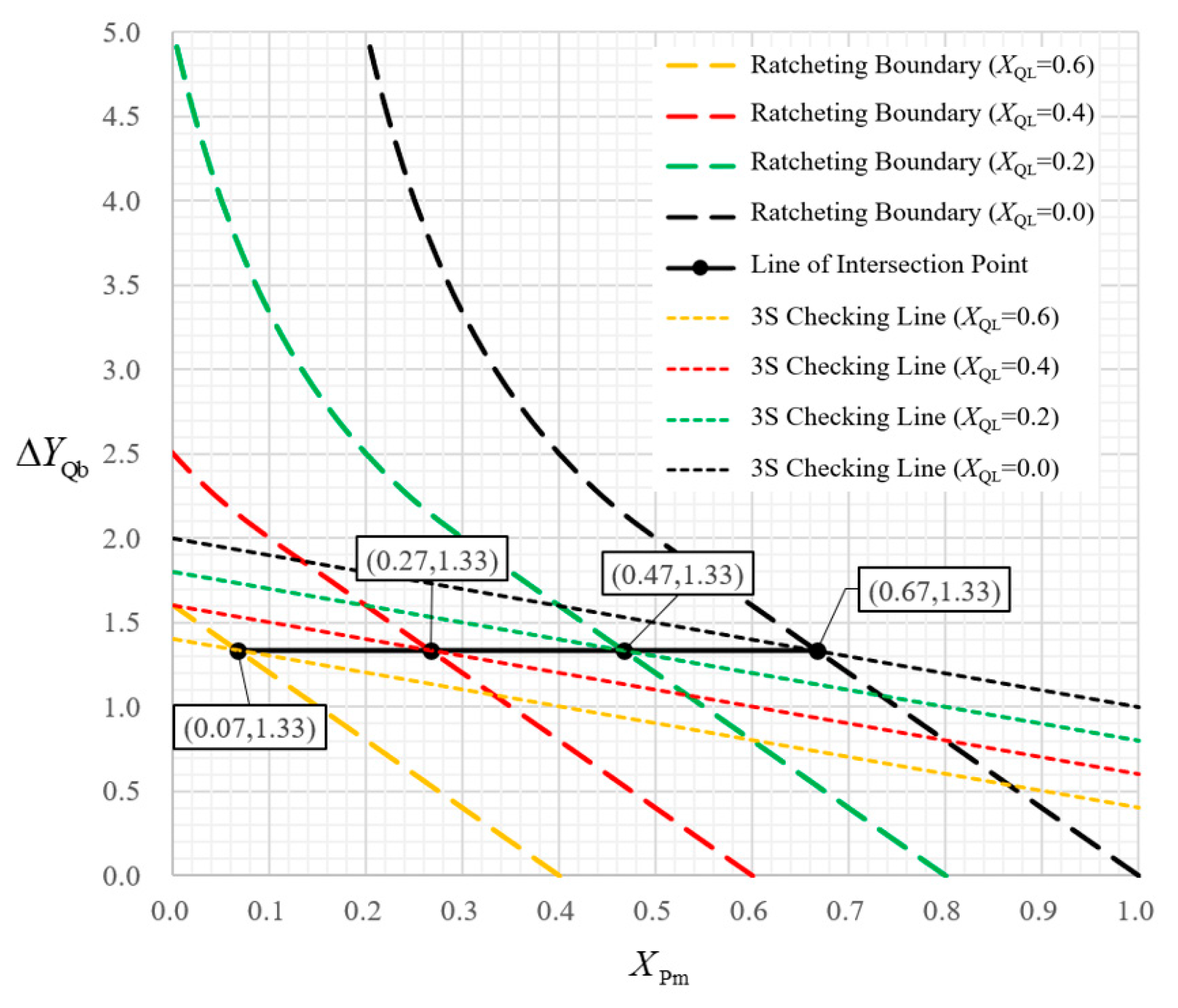
Alternative 1 is based on the translation method. The translation distance of the ratcheting boundary is determined by
and, furthermore, by
XQL. If
+
XQL ≤ 2/3, the modified 3S criterion referred to in Equation (4) is conservative, i.e.,
where
is controlled by Equation (13).
The difference from Method 1 is the consideration of XQL explicitly, which is the direct cause for the decrease in . When 2/3, i.e., , there is still the possibility of ratcheting failure even if the modified 3S criterion is met, and additional ratcheting assessment must be used according to Equation (10).
Compared with Method 1, the allowable limit of
extends from 2/3 to 1, and
and
XQL are distinguished from
. Their respective allowable ranges are as follows:
A simple example is used to illustrate how to use Alternative 1. Let = 0.87, = 0.67, XQL = 0.2, then, when = 2/3 − 2/3 − 0.2 = 0.47, the modified 3S line is practical and conservative. When > 0.47, the modified 3S line is inadequate and unconservative, and the supplementary assessment condition, referred to in Equation (10), should be satisfied, that is, = 4(1 − − XQL) = 4 × (1 − − 0.2) = 0.52. In this example, , therefore, both Equations (4) and (10) shall be satisfied by using the modified 3S criterion.
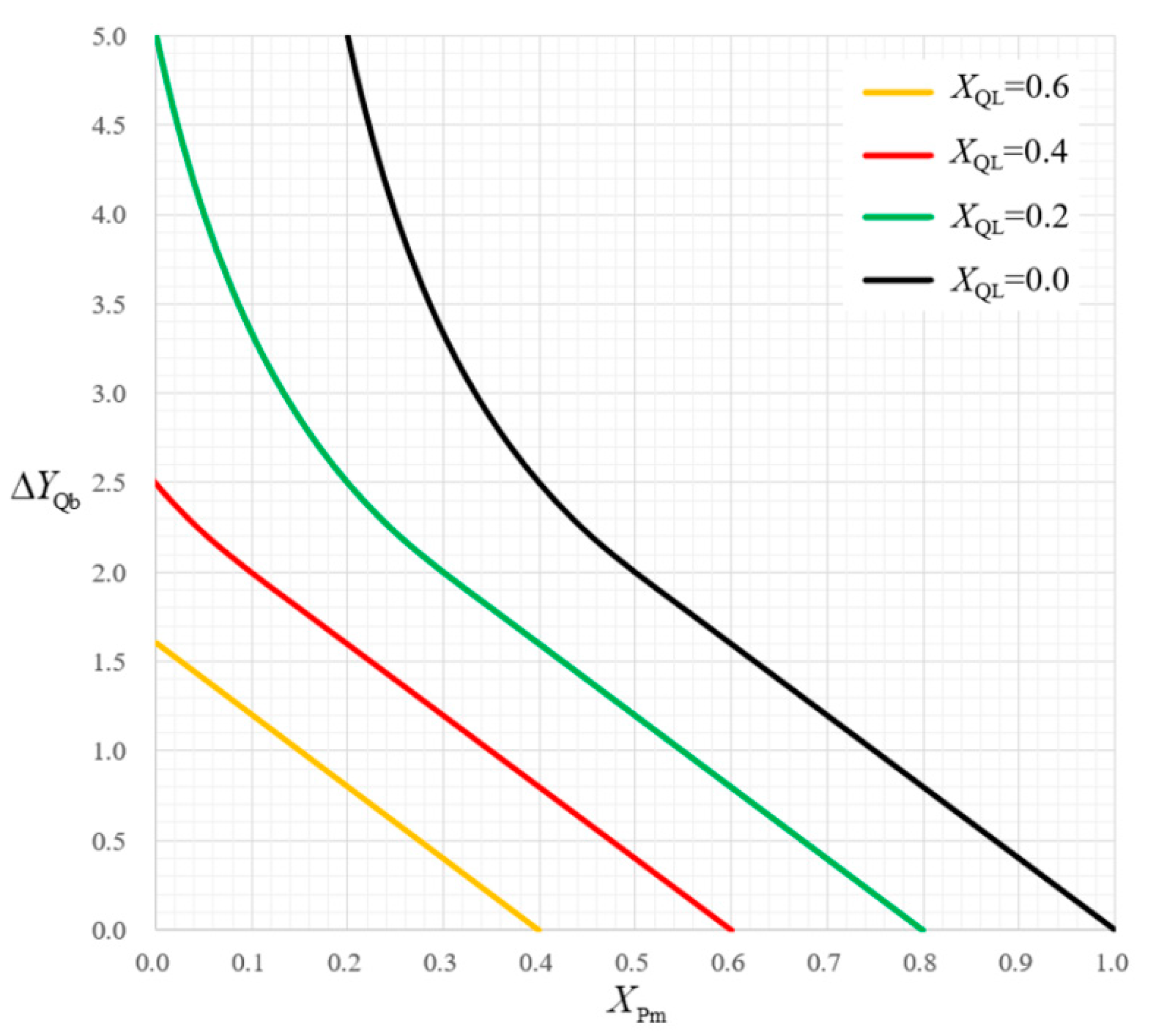
The modified ratcheting boundary considering
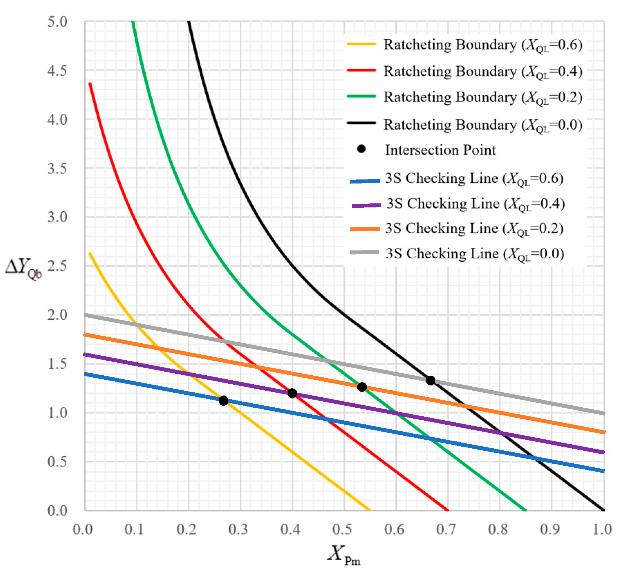
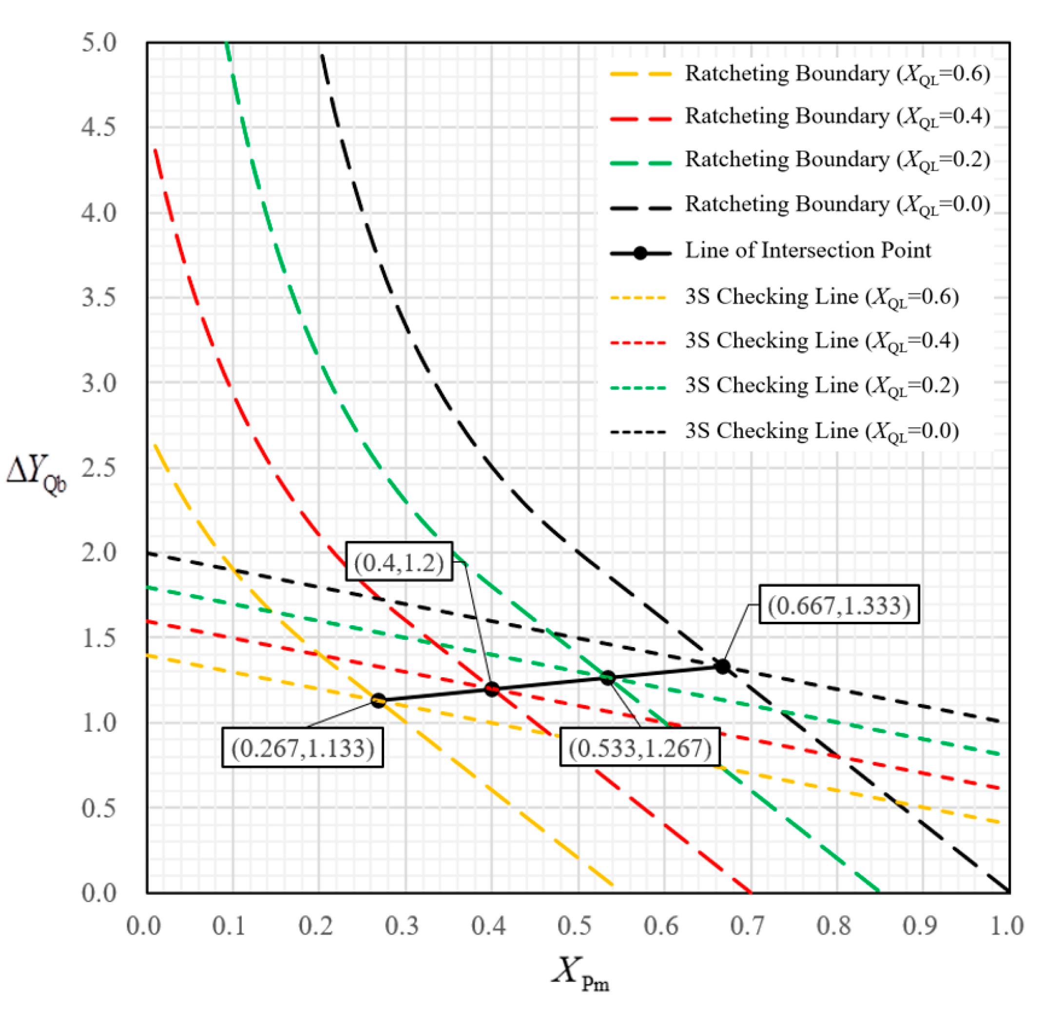
by using the noncyclic method is an important prerequisite of Alternative 2. When
, the modified 3S criterion, i.e., Equation (4), is conservative, then,
where
is controlled by Equation (15).
When , both Equations (4) and (12) shall be satisfied.
Compared with Method 1, the allowable limit of
extends from 2/3 to 1,
and
XQL are separated from
, and their respective allowable ranges are as follows:
Here is another example to illustrate Alternative 2. Let = 0.87, = 0.67, XQL = 0.2, then = = 0.53. Since = 0.67 > = 0.53, the modified 3S line is not conservative, and an additional assessment condition corresponding to Equation (12) should be added, that is, = 4(1 − ) = 4 × (1 − 0.67 − 0.15) = 0.72.
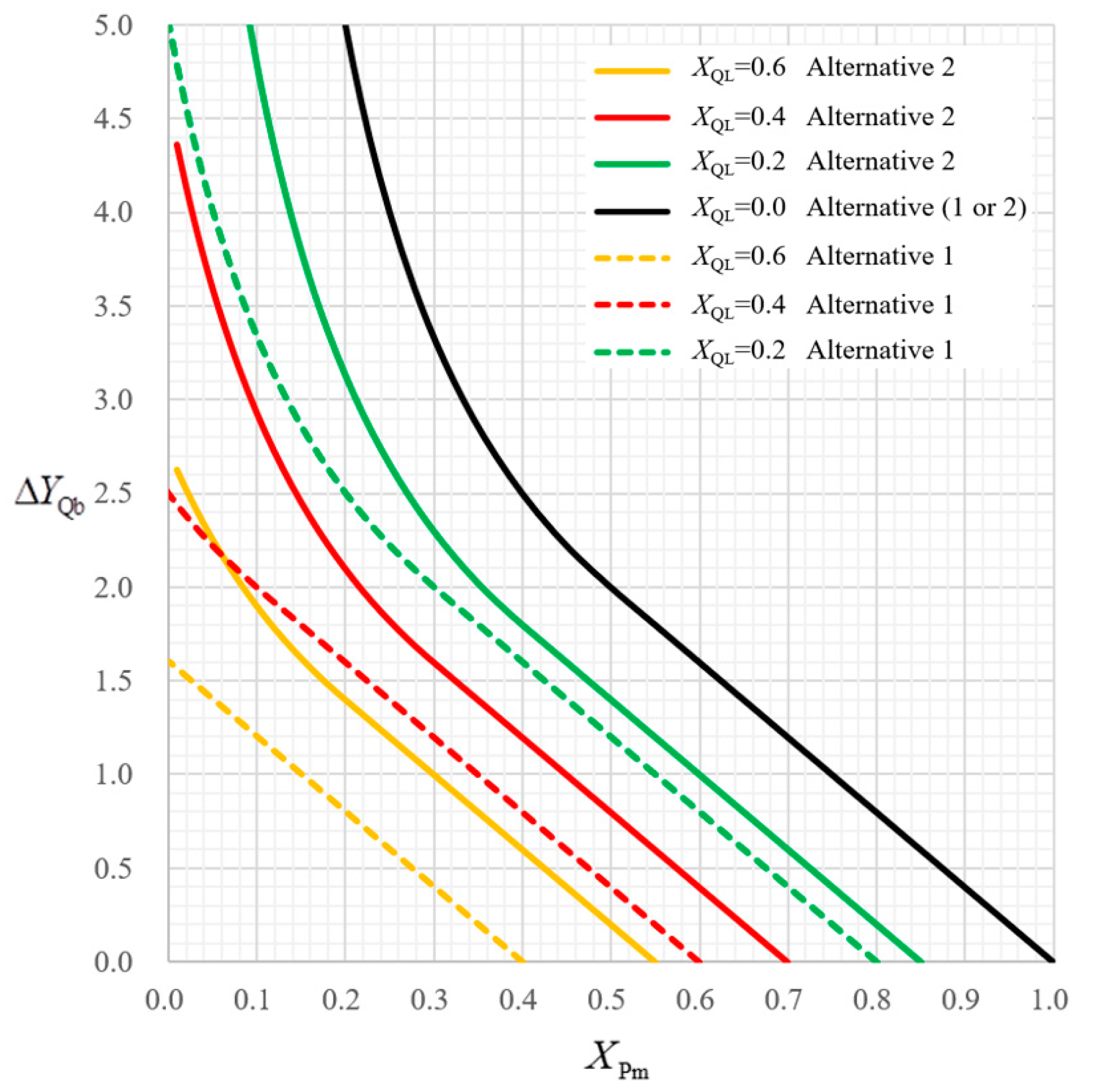
From these two examples using Alternative 1 and Alternative 2, respectively, it is obvious that the critical value in Alternative 1 is smaller than that in Alternative 2, therefore, Alternative 2 is more economical than Alternative 1 in reducing the high conservatism at discontinuities.
4.3. Discussion
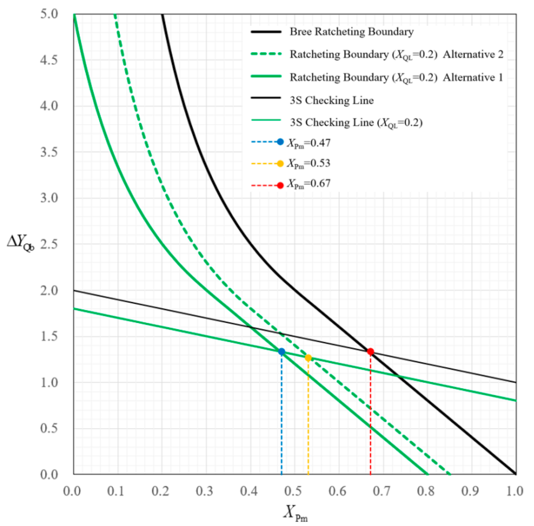
Figure 9 is used to further discuss the differences and relationship of these two methods.
Based on Method 1, the black solid lines corresponding to are the original Bree ratcheting boundary and 3S checking line, respectively, then the abscissa value of the intersection is 0.67, that is, = 2/3. That is exactly the 3S criterion with its conservativeness.
The heavy green solid line is the modified Bree ratcheting boundary obtained from Alternative 1 in Method 2 when = 0.2, the thin green solid line is the corresponding modified 3S line, and the abscissa value of their intersection is 0.47. The blue dashed line is the critical boundary showing whether to add an additional assessment condition. When = 0.47, the modified 3S line (thin green solid line) is under the thick green solid line, in other words, the modified 3S line can ensure the absence of ratcheting. However, if > 0.47, the thin green solid line is above the thick green solid line, beside the modified 3S line, and additional assessment, in the form of Equation (10), should be added.
Another similar example is the thick green dotted line and the thin green solid line, obtained using Alternative 2 in Method 2 when = 0.2. = 0.53 is the abscissa value of their intersection, and the yellow dashed line is the critical boundary showing whether to add an additional assessment condition. If > 0.53, Equation (12) as a supplement is necessary.
It is obvious from
Figure 9 that the safe domain, formed by the thick green dotted line, the yellow dashed line, and two coordinate axes, is larger than the one formed by the heavy green solid line and the blue dashed line. So, Alternative 1 is more conservative than Alternative 2. With a larger allowable limit of
, Alternative 2 is more economical.
Method 2 is a new elastic ratcheting assessment method considering , which provides two alternatives with different conservativeness. Alternative 1 and Alternative 2 are both complete elastic ratcheting assessment criteria compared with Method 1 (the current practice of the ASME Code) based on the whole elastic shakedown boundary. The nonconservatism of the 3S criterion is eliminated by supplementing additional assessment condition when 2/3, and secondary mechanical membrane stress is explicitly considered in elastic ratcheting assessment, whose allowable range and effect can be clearly determined. When = 0, the critical values of for Alternative 1 and Alternative 2 are the same as in Method 1 ( = 2/3).
For Alternative 1 and Alternative 2, the following formulas hold:
in the new method is considered to be “pure” general primary membrane stress. A part of the original primary membrane stress with the characteristics of secondary stress () is separated explicitly, which is assumed to be constant in Alternative 1 and cyclic in Alternative 2. The safe domain for primary membrane stress has been enlarged, and some of the high conservatism at discontinuities can be reduced.
5. Elastic Stress Ratcheting Assessment Considering
5.1. Simplified Elastic Stress Ratcheting Assessment Considering
If the limit on primary plus secondary equivalent stress range may be exceeded, then the simplified elastic–plastic analysis should be performed. Correspondingly, the component usually behaves as plastic shakedown, and it is essential to adopt the thermal stress ratcheting assessment based on the ratcheting boundary. In order to improve the simplicity and applicability of the modified Bree ratcheting boundaries proposed in
Section 3, two simplified elastic stress ratcheting assessment methods considering
based on conservative fitting equations are proposed.
The Bree ratcheting boundary and the two kinds of modified ratcheting boundaries considering are all controlled by two governing equations, and different equations should be used according to different intervals of . In order to avoid the inconvenience of partition assessment, the upper and lower modified ratcheting boundaries can be replaced by a unified and conservative fitting equation to extend its application scope to whole interval, that is, 0 < < 1.0 − (Alternative 1) or 0 < < 1.0 − (Alternative 2). A simplified elastic stress ratcheting assessment method considering is only composed of one equation.
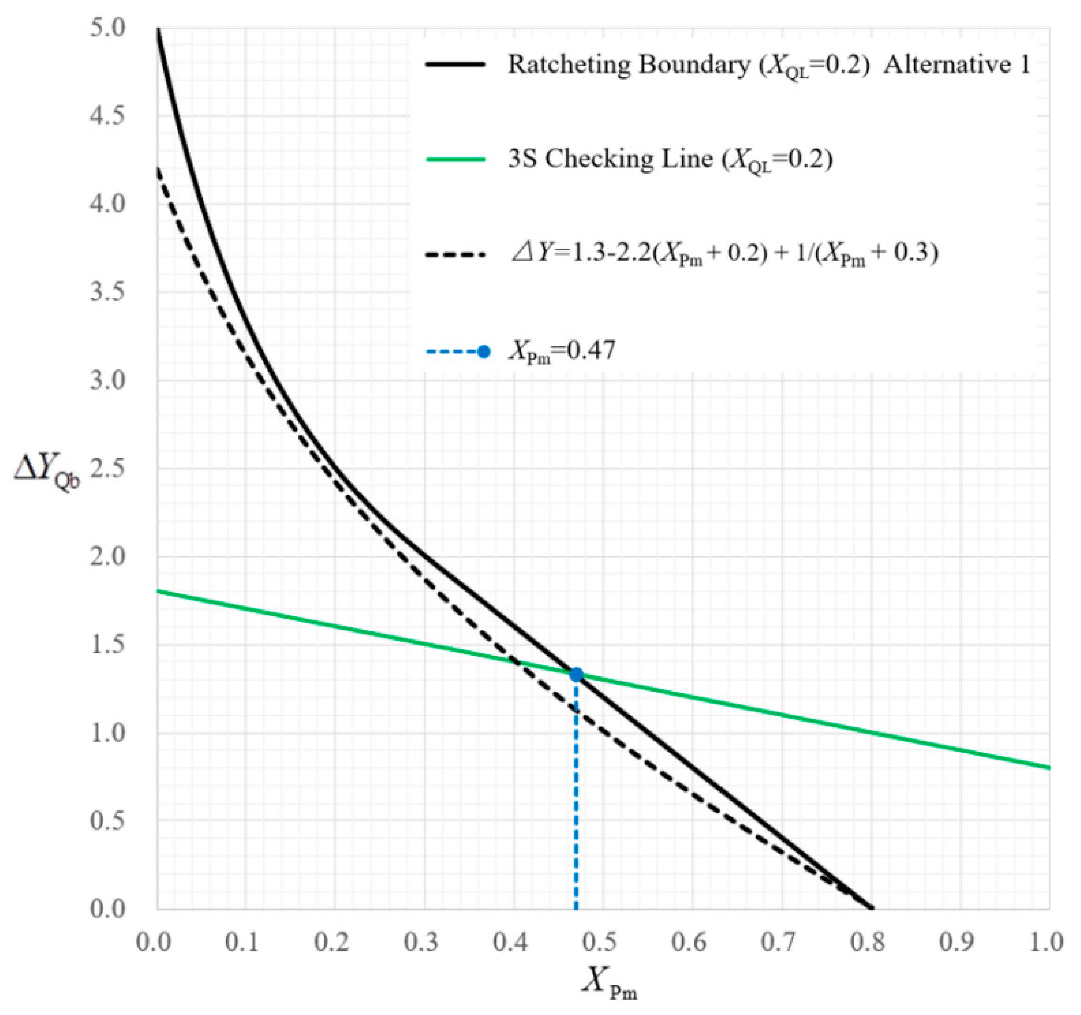
For the first kind of modified Bree ratcheting boundary (Alternative 1), Equation (30) can be used for thermal stress ratcheting assessment:
where 0 <
< 1.0 −
, 0 ≤
< 2/3. When
= 0.2, as shown in
Figure 10, the simplified ratcheting boundary marked as the black dotted line is below the modified Bree ratcheting boundary marked as the black line, so its conservativeness can be ensured. It is also easy to perform for simplified elastic–plastic analysis.
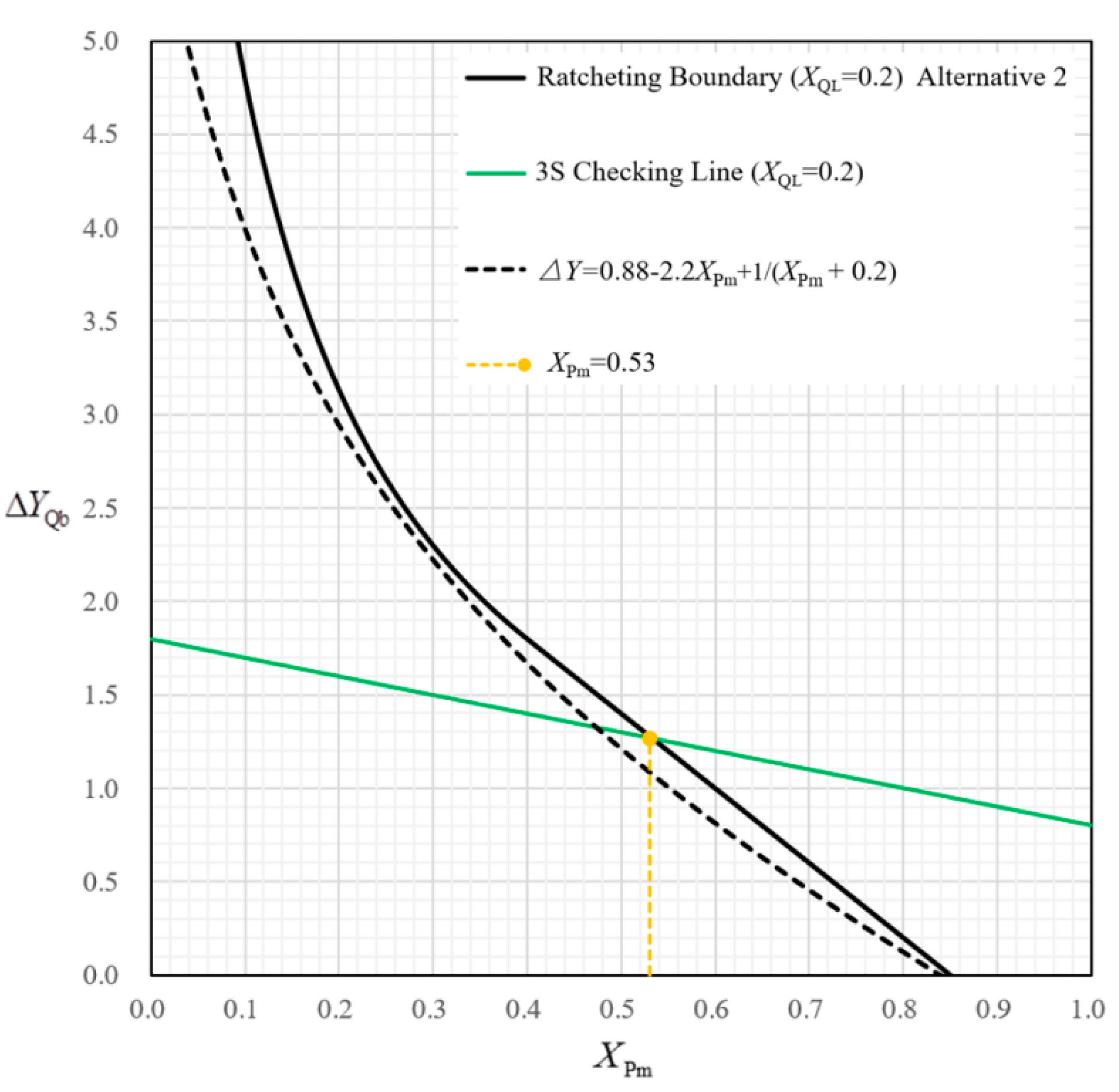
In the case of the modified Bree ratcheting boundary corresponding to Alternative 2, Equation (31) can be used for thermal stress ratcheting assessment:
where 0 <
< 1.0 −
, 0 ≤
< 1. When
= 0.2, as shown in
Figure 11, the simplified ratcheting boundary, marked as the black dotted line, is also below the modified Bree ratcheting boundary, i.e., the black line, so, it is complete and conservative for simplified elastic–plastic analysis.
In summary, the simplified elastic stress ratcheting assessment considering has the following advantages:
- (1)
Only one governing equation.
- (2)
The control equation is applicable in the whole interval 0 < < 1.0 − (Alternative 1) and 0 < < 1.0 − (Alternative 2) to avoid segment treatment of ratcheting assessment. It is feasible and easy to perform in engineering applications.
- (3)
The simplified ratcheting boundary is slightly more conservative than the original modified Bree ratcheting boundary.
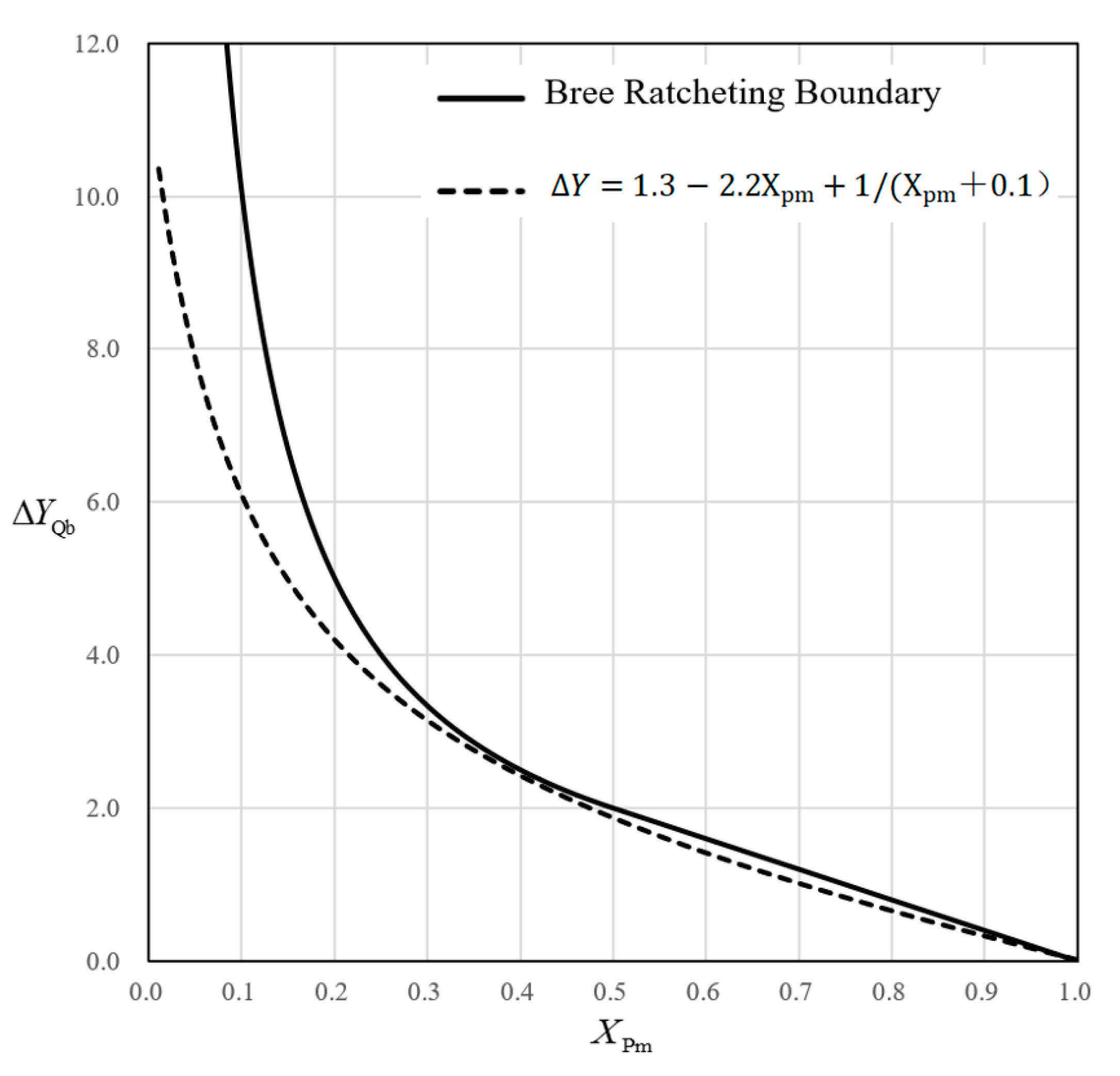
When
= 0, Equation (32) can be degenerated from both Equations (30) and (31), which is represented by the dotted line in
Figure 12, and the solid line is the original Bree ratcheting boundary.
5.2. Universal Elastic Stress Ratcheting Assessment Considering
Two methods are provided for elastic stress ratcheting assessment in ASME VIII-2, one is elastic ratcheting analysis known as the 3S criterion, the other is thermal stress ratcheting assessment. The 3S criterion, derived from the alternating plastic boundary (also known as the upper elastic shakedown boundary), is a criterion for judging the occurrence of low-cycle fatigue. It is not a complete elastic ratcheting assessment criterion when considering . Thermal stress ratcheting assessment is based on the complete ratcheting boundary, including the upper and lower boundaries, where the upper ratcheting boundary is a plastic shakedown boundary and the lower ratcheting boundary is consistent with a lower elastic shakedown boundary. The alternating plasticity boundary and the upper ratcheting boundary are separated by a plastic shakedown zone, where the structure behaves as plastic shakedown in this zone. The damage accumulation caused by alternating plasticity will lead to low-cycle fatigue failure, therefore fatigue analysis should be performed according to the simplified elastic–plastic analysis.
Based on the above relationships and ideas, three sections of “elastic ratcheting analysis”, “simplified elastic–plastic analysis”, and “thermal stress ratcheting assessment” can combine into one section in ASME VIII-2, and the following universal method of elastic stress ratcheting assessment considering is proposed.
1. To prevent ratcheting, the allowable limit on secondary equivalent thermal bending stress range when applied in conjunction with a steady-state general or local primary membrane equivalent stress is determined by Equation (33) or Equation (34):
where 0 <
< 1.0 −
, 0 ≤
< 2/3.
where 0 <
< 1.0 −
, 0 ≤
< 1.
2. If the following equivalent stress limit on the range of primary plus secondary equivalent stress is exceeded,
but the range of primary plus secondary membrane plus bending equivalent stress excluding thermal bending stress is less than
Sy and the ratio of yield strength to tensile strength of the material is less than or equal to 0.80. To prevent low-cycle fatigue, simplified elastic–plastic fatigue analysis should be used, in which the value of the alternating stress range in the section 5.5.3.2 of ASME VIII-2 [
10], Step 4 is multiplied by the factor
Ke,k.
Thus, a universal elastic stress ratcheting assessment method considering explicitly can comprise Equations (33) and (35), or Equations (34) and (35), which is based on the simplified ratcheting boundary. When = 0, Equations (33) and (34) are equivalent, and these two alternatives are unified.
6. Conclusions
Since the ASME VIII-2 2007 edition, thermal stress ratcheting assessment is not only limited to the shell but also applicable to the gross structural discontinuities, and the primary membrane stress can be global or local. The local primary membrane stress , resulting from the structural discontinuity effect induced by pressure, usually exhibits some characteristics of the secondary stress . Nevertheless, it is hard and complicated to separate them exactly, so is not always considered explicitly and just treated as a primary membrane stress in the current Code. That is the situation when = 0 in this paper. The influence of cannot be ignored in elastic stress ratcheting evaluation and it is too conservative to apply so strict a limit on the primary membrane stress at the discontinuity region, such as the shell-to-head junction or the shell-to-nozzle junction.
In this paper, secondary mechanical membrane stress () is separated from and considered explicitly in elastic stress ratcheting assessment. In summary, the following conclusions can be drawn:
- (1)
is considered in Bree ratcheting boundary by two proposed ways, i.e., the translation method and the noncyclic method. The modified Bree ratcheting boundaries are derived respectively by using these two methods. The formulas of the intersection coordinate between the modified 3S line and modified Bree ratcheting boundaries are given in order to determine the critical value below which the modified 3S criterion is conservative when considering .
- (2)
As an extension of the 3S criterion, two complete elastic ratcheting assessment schemes (Alternative 1 and Alternative 2 in
Section 4.2) considering
are proposed based on the modified elastic shakedown boundaries. The complete elastic shakedown boundary is used to ensure the conservativeness when
exists, and the application scope of the primary membrane stress can be also extended to the whole interval of
. Two simple examples are presented to illustrate the two methods. It can be concluded that Alternative 2 is more economical than Alternative 1 in reducing the high conservatism at discontinuities, and the allowable limit of
is larger for Alternative 2.
- (3)
Two simplified elastic stress ratcheting assessment methods considering are proposed, based on the fitting equations of the modified Bree ratcheting boundaries. It is only composed of one equation, and the application scope of coordinate is extended to the whole intervals 0 < < 1.0 − (Alternative 1) and 0 < < 1.0 − (Alternative 2). It is an extension of the elastic ratcheting analysis into the plastic shakedown region. These simplified elastic stress ratcheting assessment methods in this paper can be used as a conservative replacement of the thermal stress ratcheting assessment for the simplified elastic–plastic analysis when the modified 3S criterion is exceeded.
- (4)
A universal method of elastic stress ratcheting assessment considering is proposed to combine the considerations of “elastic ratcheting analysis”, “simplified elastic–plastic analysis” and “thermal stress ratcheting assessment”. This ratcheting assessment based on a simplified ratcheting boundary can be as a replacement for both elastic ratcheting analysis and thermal stress ratcheting assessment. Nevertheless, the modified 3S criterion is used to judge whether simplified elastic–plastic analysis can be used to protect against fatigue failure.
In summary, the evaluation method for elastic stress ratcheting effects considering proposed in this paper breaks the conservative restrictions on stress evaluation in discontinuous regions in current specifications. It significantly improves the economy and operability of the design on the premise of ensuring equipment safety by clarifying the influence of , optimizing evaluation boundaries, and simplifying the evaluation process, which is conducive to reducing manufacturing costs and enhancing product competitiveness especially at a structural discontinuity. Moreover, the proposed single-equation fitting eliminates the need for segmented verification and has engineering practicability.
