Abstract
Embedded steel ring connections are widely used in onshore wind turbines (WT) to transfer loads from the tower to the foundation. The structural behavior of the embedded steel ring connection greatly affects the structural integrity of wind turbines under ultimate loads. Approximately 90% of the bending loads (bending/overturning moments) are carried by the base flange of the embedded ring and the embedded ring–concrete contact surfaces. Damage that may occur in these areas significantly affects the tower’s stability and may lead to the tower overturning. The damages that may occur in these areas are the most dangerous that can occur in wind turbines. This study proposes a strengthening method for wind turbine foundations with damaged tower–foundation connections. In order to investigate the effect of the developed strengthening method on the structural behavior of the tower–foundation connection and also to verify the analytical models, 1/15 scale models of an existing wind turbine and its foundation were created. The effect of the developed strengthening method on the tower–foundation connection was investigated by testing the created models in a laboratory environment.
1. Introduction
Given the rapid and continuous development of the global economy, energy supplies have increased significantly worldwide, leading to the depletion of non-renewable energy sources (oil, coal, etc.) [1]. Due to climate change and the conservation of fossil energy resources, wind energy has attracted worldwide attention and wind energy has become one of the fastest growing energy sources in the world [2]. With the development and utilization of wind resources, the global wind energy industry in the 21st century is developing rapidly and a large number of wind turbines are in service [3,4,5]. According to the Global Wind Energy Council (GWEC 2024) data, the total installed capacity in the world by the end of 2024 has reached 1096 GW (GW: Gigawatt) and the top five countries are China (403 GW), USA (150 GW), Germany (61 GW), India (44 GW), and Spain (30 GW) [6]. Statistics published by the Global Wind Energy Council (GWEC 2024) show that onshore wind farms account for a large share of the total wind energy market [6]. It is also predicted that onshore wind power generation will continue to grow at an increasing rate in the coming years [7,8].
A wind turbine is a complex structure with electronic, mechanical and structural components, including many structural elements with high damage possibilities. The structural safety of onshore and offshore wind energy structures is directly related to the safety and stability of the tower and foundation system [9,10]. Damage to the tower and foundation system, which is the main and even the only carrier system of the wind turbine, directly causes collapse. It is possible to classify the structural damages encountered in the carrier systems of wind turbines as tower, blade, foundation, and tower–foundation connection damages. Especially, the tower–foundation connection damage mechanism is a common problem in wind turbines. In a 2008 study, damages on wind turbines were categorized according to element types [11]. According to the aforementioned study, structural system damages are at the level of 4% when all damage types are taken into consideration. Since 2008, the size of wind turbines has gradually increased, and it is estimated that the percentage of damage to the structural system has increased compared to the total damage distribution [6]. However, in any case, tower and foundation damage have very serious consequences since these structures have only one structural element. Therefore, the safety/stability of the wind turbine foundation is of great importance for the structural integrity and safe operation of the wind turbine [12,13].
The forces generated in the wind turbine tower due to environmental and operational effects are transferred to the foundation by the connection parts that provide the connection between the tower and the foundation. The connection between the tower and the foundation is provided by commonly used embedded ring or anchor cage fittings, which are placed inside the foundation [14,15,16,17]. An embedded ring is used as the old manufacturing model, and rod anchor tower–foundation connection methods are used as the new manufacturing model. In addition to these, the Adapter (Hybrid) connection method is also applied [18]. Wind turbine foundations with embedded ring connections were widely used in the early periods when these turbines started to be used due to their ease of installation and application [19]. The embedded ring connection type is a preferred system due to its easy construction and high flexural stiffness [20]. The majority of onshore wind turbine foundations currently installed in the world have this connection type, which can be characterized as an old type. Compared to other connection types, it has been observed over time that structural damages occur more frequently in this connection type. Different shrinkage rates between the embedded ring and concrete cause cracks to form at the interface between the ring and the foundation, and the embedded ring is subjected to small displacements within the foundation due to the loads from the superstructure [21]. Water ingress into these cracks occurs over time, and the cracks gradually enlarge with the increase in voids and segregation around the ring [17]. Over time, due to various damages that occur in such connections, the load-carrying capacity of the foundation is significantly reduced, and situations that may result in the collapse of the tower may occur. Therefore, it is considered important to develop strengthening methods for wind turbines with embedded ring tower–foundation connections. To develop an efficient strengthening method for wind turbines where the connection between the tower and the foundation is provided by an embedded ring, it is first necessary to understand the behavior between the embedded ring and the foundation. The most suitable method for this is the finite element method (FEM). Numerical simulations using the finite element method provide a reliable and cost-effective alternative to investigate the behavior of the tower–foundation connection of onshore wind turbines under different loading conditions [20,22,23,24,25,26]. However, most of the previous studies have focused on the long-term behavior of the foundation under fatigue loads [27]. Only a few studies [22,26,27,28] have focused on the behavior of the embedded ring–foundation connection under ultimate loads.
The most commonly used repairing method for foundations with embedded ring connection type is to drill holes in the upper surface of the foundation and inject cement mortar to fill the voids and cracks. This method may have an immediate strengthening effect, but since the force transmission mechanism between the steel embedded ring and the concrete is not changed, voids and cracks reappear in a short time. Improvement methods applied for damages occurring at the wind turbine tower—foundation interface with embedded ring connection type are aimed at repairing the structure rather than strengthening it. It is not known how much these methods strengthen the tower–foundation connection and whether it reaches the targeted performance level, since it cannot be measured after the applied procedure. Within the scope of this study, the damaged reference model was repaired with the injection method, which is one of the most preferred repairing methods in practice, and the effect of this strengthening method on the foundation was also investigated by re-testing. In this way, the strengthening method developed and the strengthening method frequently preferred in practice could be compared.
In structural strengthening, techniques such as strengthening reinforced concrete or steel elements, crack injection methods, and the integration of damping systems are employed to improve load-bearing capacity and seismic performance [29,30]. Damping devices, in particular, significantly enhance structural safety and durability by effectively reducing vibration energy induced by dynamic loads [31]. In structural engineering, damping systems are energy dissipation devices used to improve the safety and durability of structures under dynamic effects such as earthquakes, wind loads, and mechanical vibrations. These systems reduce vibration amplitudes, thereby increasing the fatigue life of structural elements and enhancing user comfort. Damping systems are generally classified into passive, semi-active, and active categories, with passive systems widely used due to their low cost, reliability, and independence from external power sources. Within this context, passive damping systems developed for flexible and tall structures such as wind turbines are often implemented in the form of spring-based dampers. These systems are particularly effective in mitigating low-frequency oscillations in tall turbine towers. Tuned Mass Dampers (TMDs), consisting of a mass, spring, and damping element, are tuned to the natural frequency of the structure and significantly reduce tower vibrations, thereby extending the structural fatigue life [32]. Advanced systems such as the Spring–Pendulum–Pounding Tuned Mass Damper (SPPTMD) have shown improved performance in monopile-based offshore wind turbines by offering effective damping over a wider frequency range and exhibiting greater tolerance to detuning [33]. Furthermore, K-Dampers incorporating negative stiffness elements provide high isolation performance without the need for large additional masses, making them an advantageous alternative to conventional TMD [34]. Due to their low maintenance requirements and reliable long-term performance, spring-based damping systems are increasingly preferred in both onshore and offshore wind turbine applications. Damper systems of the spring type or with different operating principles used in wind turbines are often preferred to dampen the vibration caused by electronic components in the upper region of the tower and to improve tower behavior. The damping systems mentioned above are located in the upper region of the wind turbine tower (inside the nacelle), so they dampen mechanical vibrations but do not affect the structural behavior of the tower–foundation connection region because they are not located in that region. By installing damping systems in the tower–foundation interface region, it will be possible to strength wind turbines with structural issues in this region.
This study presents a new retrofit/strengthening solution for strengthening existing wind turbine foundations by using spring-type dampers to resist lifting loads and reinforce concrete against tensile forces. Two 1/15 scale models of wind turbines were fabricated together with their foundations. One of these models was accepted as a reference sample, and the other one was fitted with dampers, and the cyclic loading test (Quasistatic Test) was performed on both models. As a result of the tests, force–displacement relations of both models were obtained. In addition, the injection method, which is frequently preferred in the repairing of existing wind turbine foundations, was applied to the damaged model, and the tests were repeated, and the effect of this method was investigated comparatively with the developed strengthening method. In this study, in parallel with the experimental study, finite element analysis (FEA) was performed for the reference and damper-strengthened models, and force–displacement relationships were obtained. After the study, the displacement-dependent horizontal load-carrying capacities of the reference and strengthened models are presented both experimentally and analytically, and the efficiency of the developed strengthening method is evaluated. The developed strengthening method is also analytically applied to an existing wind turbine foundation, and the results are evaluated.
The tests revealed that the model strengthened with spring-type dampers had a 33% increase in load-bearing capacity compared to the reference model. The tests also determined that the injection method repaired existing cracks but did not increase the overall capacity of the system. The force–displacement curves obtained from the finite element analyses were found to be consistent with the force–displacement values obtained from the experimental studies. This demonstrates that the detailed finite element models accurately simulate/represent the actual behavior. The effect of the proposed strengthening method on an existing wind turbine foundation was also determined through finite element studies. The analyses revealed that the proposed strengthening method reduced the stresses around the embedded ring base flange (the area where cracks are most common in concrete) by 80%, altered the stress distribution within the foundation, and increased the system’s load-carrying capacity by over 100%. The finite element studies showed that the strengthening method developed for wind turbines with a tower–foundation connection type of embedded ring works efficiently and is feasible.
2. Developed Strengthening Method
A new strengthening proposal/solution using spring-type dampers has been developed to improve existing wind turbine foundations, resist lifting loads, and strengthen the concrete against tensile forces. The main purpose of the proposed retrofit/strengthening design is to improve the compressive stress distribution between the embedded steel ring and the reinforced concrete foundation to increase the structure to the desired performance level and also to prevent the formation of new cracks in the concrete by closing the cracks formed by changing the force transfer mechanism between the embedded ring and the concrete. This proposed solution will provide the ability to withstand the stresses caused by the service loads by preventing the concrete from cracking, and then the fatigue life of the concrete will be increased as the cyclic stress amplitude is reduced.
The developed strengthening design consists of a concrete ring, steel plates, and spring-type dampers, which are applied around the embedded ring–foundation joint area forming the tower–foundation connection and are ring-shaped in plan. The developed retrofit/strengthening design mainly consists of three main applications: (i) placing steel plates (flag plates—feder) in the tower–foundation joint area, (ii) sealing the placed steel plates with concrete ring, and (iii) then, adding spring-type dampers to complete the retrofit/strengthening design (Figure 1).
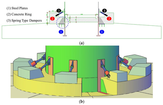
Figure 1.
The developed strengthening method (a) section detail and (b) 3D view.
Disk springs (Belleville springs) are used in the spring-type damper developed to strengthen the tower–foundation connection (Figure 2). Disk springs are preferred due to their ability to carry large loads in small volumes, and at the same time, they can be brought to the desired capacity by adding and removing springs. Disk springs can be connected in series or in parallel to achieve different force-response characteristics. When connected in series, greater deflection (deformation) is achieved, while when connected in parallel, higher load capacity is obtained. These connection methods allow the system’s rigidity and energy-damping capacity to be adjusted as desired. In the developed spring-type damper, disk springs are connected both in parallel and in series to increase both deformation capacity and load-carrying capacity. By changing the connection configurations and the number of springs, the spring capacity can be adjusted to the required level. Disk spring elements are manufactured from 50 CrV4 alloyed special steel material. 50 CrV4 spring steel is an alloyed material delivered in a pre-hardened state. Unlike other carbon and alloy steels, 50 CrV4 material possesses high hardness, resistance to heavy loads, and the ability to operate at high temperatures up to 300 °C. The minimum yield strength of 50 CrV4 steel is 550 MPa for diameters up to 250 mm.
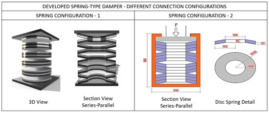
Figure 2.
Spring-type damper detail.
The reinforcing concrete ring in this strengthening system increases the embedment depth of the embedded ring in the foundation and contributes positively to the improvement of the moment-carrying capacity of the ring. Spring-type dampers, which are the main elements of the strengthening system, will be used to close the cracks formed by changing the force transfer mechanism between the embedded ring and the concrete and prevent the formation of new cracks in the concrete. The wind turbine tower tends to overturn under the effect of overturning moment caused by environmental load effects such as wind, earthquake, etc., and with this strengthening method developed, the tower will be prevented from overturning.
3. Experimental Studies
Large-scale tests to investigate the load-carrying behavior of the embedded ring–foundation connection in wind turbines with an embedded ring connection type would be extremely expensive and time consuming due to the huge dimensions of the various components of the connection. Considering this challenge, small-scale (1/15 scale) models of the tower, foundation, and connection were developed and tested under cycling loading conditions in the laboratory of Ege University. The purpose of the test is to investigate the effect of the developed strengthening method on the load-carrying capacity of the connection and also to provide data for the validation of subsequent analytical models.
3.1. Model Specifications and Test Setup
For this study, two identical specimens, a reference specimen and a specimen reinforced with a spring-type damper, were produced. The large-scale model of the test specimens belongs to an existing wind turbine and its foundation located in Turkey (Figure 3). The existing foundation is circular with a diameter of 16.7 m. The foundation depth is 2.53 m, and the embedment depth of the embedded ring in the foundation is 1.58 m. The ratio of the embedment depth to the foundation depth is 0.63. The foundation volume is approximately 650 m3, and the total weight of reinforcement (rebar) in the foundation is 48.47 tones. The total weight of the foundation is 1480 tones. The material class and quality used in the foundation are C25/30 for concrete and S420 for reinforcement. The existing tower generates electricity with a power of 3 MW, and the tower hub height is 80 m.
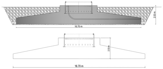
Figure 3.
Specifications of existing wind turbine foundation (Units: m).
It is seen that 1/4, 1/12, 1/15, and 1/20 scale models have been created in the literature in accordance with the parameters examined and the scope of the study in order to carry out laboratory scale tests [35,36,37]. Considering the laboratory conditions where the tests are planned to be carried out, it was decided that the most appropriate scale to be studied for the existing tower and foundation connection would be λ = 1/15. In order to create a laboratory scale tower and foundation model and perform tests on it, the existing circular foundation was scaled to the specified scale value (1/15). The geometrical features of the scaled model are presented in Figure 4.
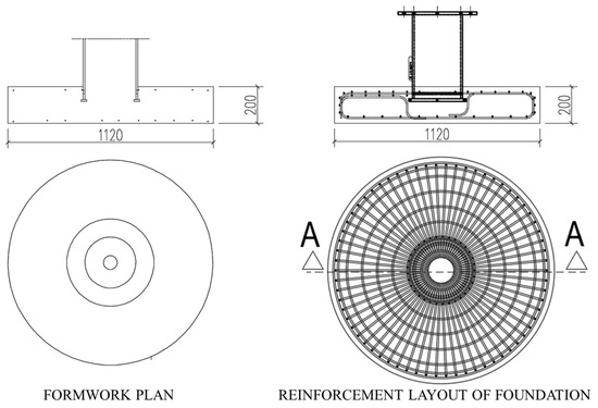
Figure 4.
Scaled model specifications (unit, mm).
The existing tower and foundation were designed according to the load values specified by the manufacturer. In order to make the reinforced concrete design of the scaled foundation model and for the tests to be applied in the laboratory to reflect the current situation in the best way, the design loads were scaled at the specified scale (1/15) (Table 1).

Table 1.
Design loads.
These loads are the scaled model foundation design loads, and the foundation reinforcements were determined as a result of the analyses performed according to these loads. The total weight of the three meter long steel pipe profile is 232 kg. In order to reflect the vertical stresses in the existing foundation in the scaled model, the total weight should be 1140 kg. Therefore, a pressure force of 900 kg will be applied to the scale model.
Two identical wind turbine specimens to be used in laboratory experiments were manufactured in λ:1/15 scale. Working visuals of the fabrication are presented in Figure 5. The circular foundation diameter for both specimens is 1.2 m, and the foundation height is 0.20 m. Turbine heights are 2 m from the bottom of the foundation to the horizontal load impact point. In both specimens, the flange element in the embedded ring was placed approximately 70 mm below the top of the foundation. The experimental setups of the reference and strengthened specimens are shown in Figure 6.
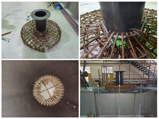
Figure 5.
Scaled wind turbine model manufacturing stages.
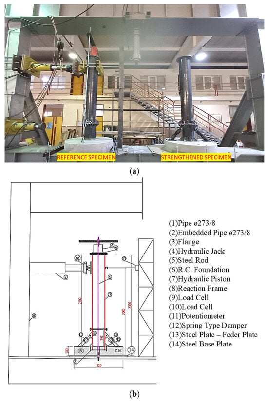
Figure 6.
(a) Reference and strengthened specimen, (b) the experimental setup.
The test setups of the reference and strengthened specimens are shown in Figure 6.
In Figure 6b, (1) the body pipe is an Ø273/8 mm steel pipe, (2) an Ø273/8 mm embedded pipe, and (3) circular steel flange elements welded to the end of the embedded pipe. The flange element is designed to be 20 mm outside the embedded pipe element. A jack was used to transfer the scaled vertical load representing the wind turbine weight to the foundation (4). The vertical load is transferred by means of vertical steel rods (5) placed between the bottom plate (7) and the top plate (10) placed under the foundation. The scale λ2 was taken into account in determining the scaled vertical load. The weight of the tower is approximately 4.5 kN, and an additional weight of 9 kN is required. The additional axial force applied to the test specimen by jacking is 9 kN. Since the diameter of the existing wind turbine foundation is 16.7 m, the foundation diameter of the test specimens was calculated as 1.11 m according to the specified scale, and the foundation diameter was selected as 1.20 m in practice. The existing foundation height is 2.53 m. When the foundation height is scaled according to the determined scale factor, it corresponds to 0.169 m. Since the determined foundation height would be difficult to implement, the foundation height was selected as 0.20 m. During the cyclic loading (Quasistatic) tests, force values are measured from load cell number 10 and displacement values from potentiometer number 11. In addition, the amount of axial load is controlled from load cell number 9. In the strengthened specimen shown in Figure 6b, in addition to all these, there is a damping system (12) and steel plates (feder—flag—bracing plates) (13). In the system, 8 steel plates are welded to the pipe and the bottom plate at the foundation level.
The developed spring-type damper was modeled and manufactured in dimensions suitable for wind turbine models created in 1/15 scale (Figure 7). A compression test was performed to determine the spring constant of the developed spring-type damper. In the tests, a compressive force was applied in the direction of the damper axis, and the vertical displacement for each force level was measured. In this way, the force–displacement relationship of the damper was determined. As a result of the tests, the spring constant (k) was determined as 0.851 kN/mm.
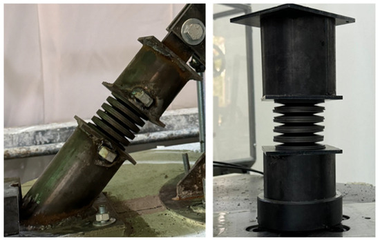
Figure 7.
Spring-type damper (1/15 scale).
After the completion of the experimental setups and spring-type damper mechanical tests, tests of the 1/15 scale models were carried out under cyclic loads. The test procedure specified in ACI 374.1.05 (2005) [38] was applied for both specimens. Cyclic loads consisting of gradually increasing displacement-controlled push and pull forces were applied to the reference and strengthened specimens. The test procedure was established according to the displacement template established according to ACI 374.1.05 (2005) [38]. Displacement-controlled cyclic loads were applied to both specimens for a total of 11 displacement ratios (0.2%, 0.25%, 0.35%, 0.50%, 0.75%, 1.00%, 1.40%, 1.75%, 2.20%, 2.75%, and 3.50%) representing the damage conditions (Figure 8).
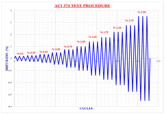
Figure 8.
Cyclic load pattern according to ACI 374.1.05 (2005).
The test specimens were subjected to in-plane cyclic displacements ranging from 0.20% displacement to 3.50% displacement. Cyclic loading consisting of 3 cycles was applied to the specimens for each displacement value.
Cyclic loading tests were performed on the reference specimen according to the test procedure described in ACI 374.1.05 (2005) [38], and the characteristic force–displacement curve of the reference specimen was obtained. After the tests were completed, the reference specimen was reinforced with injection resin, and the tests were repeated to investigate the effect of the reinforcement by injection on the foundation. The injection resin was injected into the foundation using injection dowels (injection packers). As a result of the tests, it was predicted that cracks and voids were intensively formed around the embedded ring base flange, and injection packers were placed by targeting this region. Injection packers were placed in the foundation in a way to cut the cracks formed on and inside the foundation perpendicularly. Injection packers were placed in the tower–foundation junction area where cracks occur intensively. In this way, the effect of the injection method, which is frequently preferred in the strengthening of existing wind turbine foundations, was also determined. The same test procedure was applied to the specimen strengthened with spring-type dampers, and the effect of both strengthening methods on the foundation was obtained comparatively. The test procedures are summarized in Figure 9.
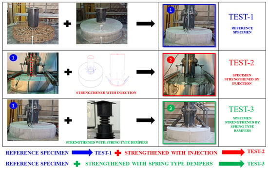
Figure 9.
Test summary.
3.2. Test Results
The tests investigated the effect of both the developed strengthening method and the strengthening method, which is frequently preferred in the strengthening of wind turbine foundations, on the load-carrying capacity of the foundation. As a result of the cyclic loading tests, hysteretic force–displacement curves were obtained for the reference and spring-type dampers strengthened specimens. The hysteretic force–displacement curve obtained for the reference specimen and the backbone curve created from this curve are shown in Figure 10.
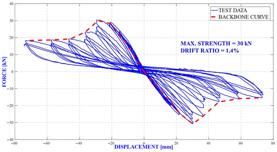
Figure 10.
Hysteretic force–displacement and backbone curves for reference specimen.
The hysteretic force–displacement curve obtained for the spring-type dampers strengthened specimens and the backbone curve created from this curve are shown in Figure 11.
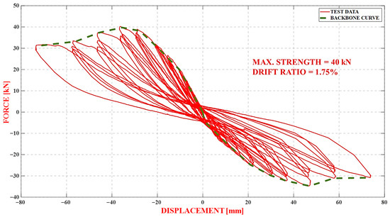
Figure 11.
Hysteretic force–displacement and backbone curves for the strengthened specimen.
The hysteretic force–displacement curves obtained for both tests are presented in Figure 12 for comparison of the results.
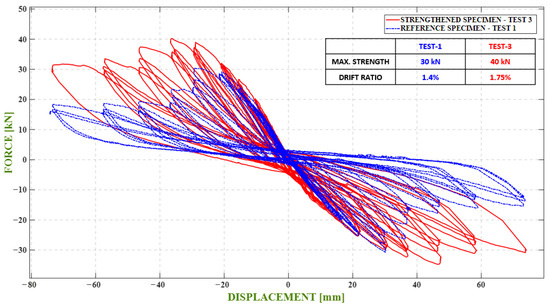
Figure 12.
Hysteretic force–displacement curves.
The effect of the strengthening methods applied was determined by comparing the backbone curves generated from the hysteretic force–displacement curves obtained as a result of cyclic loading tests (three tests in total) on the reference and strengthened specimen (Figure 13).
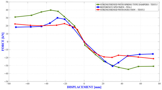
Figure 13.
Force–displacement backbone curves.
As expected, the additional lateral resistance (stiffness) provided by the spring elements is much higher than both the reference case lateral resistance and the lateral resistance provided after repairing/reinforcement with injection resin (i.e., the reinforced specimen reaches higher lateral load carrying levels compared to the reference specimen and the injection repaired/reinforced reference specimen). The reference specimen repaired/reinforced by injection reaches the lateral load-carrying capacity earlier compared to the other two cases. The specimen strengthened with springs increased the lateral load-carrying capacity by about 33% compared to the reference specimen, and the value of the translation ratio at which the load-carrying capacity was reached and shifted from 1.40% to 1.75%. This shows that the springs contribute positively to the system ductility. No increase in lateral load-carrying capacity was observed in the repairing/strengthening process with injection resin compared to the reference specimen. The repairing/strengthening treatment with injection resin enabled the reference specimen to maintain the load-carrying capacity (approximately 20 kN) at the end of the 3.50% drift ratio (i.e., the system can continue to operate from the point where it left off without capacity reduction). It can also be clearly seen from the backbone curves that the repairing/strengthening with injection resin provides additional ductility to the system. It is seen from the results of cyclic loading tests that the treatments with injection resins, etc., have a restorative effect on wind turbine foundations rather than strengthening. The stiffness change curves of the tested specimens are presented in Figure 14.
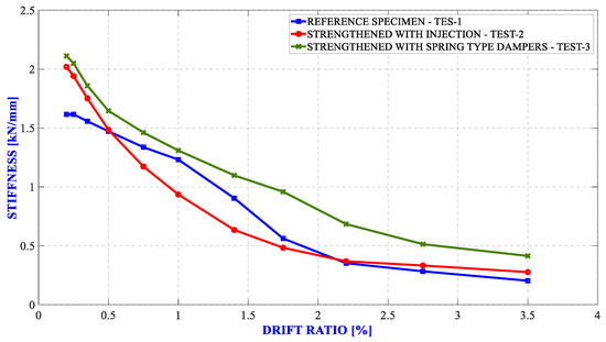
Figure 14.
Stiffness changes in test specimens.
As shown in the stiffness change curves that the undamaged reference specimen has the lowest initial stiffness value. The initial stiffness values for the reference, injection paired/strengthened reference, and strengthened test specimens were 1.6170 kN/mm, 2.0194 kN/mm, and 2.1122 kN/mm, respectively. The initial stiffnesses of the injection paired/strengthened reference specimen and the strengthened specimen are approximately 1.25 and 1.31 times higher than the undamaged reference specimen, respectively. For all displacement ratios, the stiffness of the specimen strengthened with spring elements is higher than the other two cases. After about 2.20% displacement ratio, the reference specimen and the injection repaired/strengthened specimen showed similar stiffness values. Although the injection repaired/strengthened specimen is initially more rigid than the reference specimen, it stands out as the specimen that loses stiffness at the fastest rate for increasing values of displacement ratio. The numerical information extracted for each specimen regarding the cyclic loading test results are summarized in Table 2.

Table 2.
Test results summary table.
The reference specimen reaches its maximum lateral load-carrying capacity at 1.40% deflection ratio and loses 40% strength at 3.50% deflection ratio. At 3.50% displacement ratio, the initial stiffness decreases by 87.40%. The specimen repaired/strengthened by injection reaches its maximum lateral load-carrying capacity at 1.00% drift ratio and loses 3.30% strength at 3.50% drift ratio. At 3.50% drift ratio, the initial stiffness decreases by 86.29%. The specimen strengthened with spring elements reaches the maximum lateral load-carrying capacity at 1.75% drift ratio and loses 22.50% strength at 3.50% drift ratio. At 3.50% drift ratio, the initial stiffness decreases by 80.39%.
4. Finite Element Analyses
For a comprehensive understanding of the ultimate load-carrying behavior of the tower–foundation connection of wind turbines, there is a need to develop finite element models of the connection. Finite element modeling overcomes the difficulties associated with large-scale (1/1 scale) testing of the tower–foundation connection and provides a comprehensive assessment of the stress and strain distribution at the steel–concrete interfaces. The stress and strain distributions around the embedded ring base flange–concrete and embedded ring–concrete interfaces, as well as information on possible damage locations, were obtained from the finite element analyses in order to design the strengthening method for the tower–foundation connection in an appropriate manner. In this section, 1/15 scale test specimens were modeled and the finite element model was verified according to the structural parameters obtained from the tests. Then, a large scale (1/1 scale) finite element model of an existing wind turbine foundation was created, and the effect of the developed strengthening method on an existing foundation was determined numerically.
4.1. Finite Element Analyses of Test Specimens
Three-dimensional finite element models of the test specimens (reference and strengthened specimens) were created in ABAQUS [39]. The finite element model for the reference specimen consists of the concrete foundation, strengthening elements, steel tower, and embedded tower part (Figure 15). The finite element model for the strengthened specimen was obtained by adding additional steel plates and spring-type dampers to the reference specimen model.
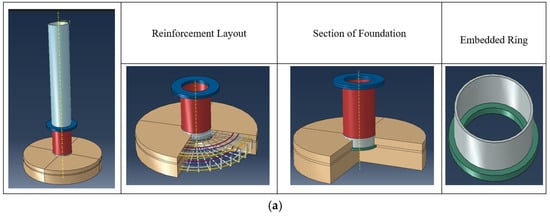
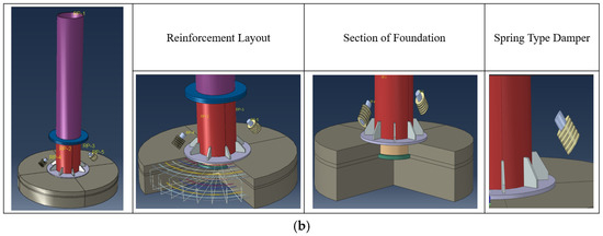
Figure 15.
Finite element solid models of the test specimens. (a) Reference and (b) strengthened model.
The material properties used in the finite element models were obtained from material tests. In the finite element analyses, foundation concrete is C25/30, reinforcing steel is S420, steel tower and plates are S355, and disk springs are 50 CrV4. The concrete model in the C25/30 class was created using the Mander [40] model (Figure 16). For the reinforcing steel bars placed within the foundation, material from the S420 steel grade with a yield strength of 420 MPa was used. For the S420 grade steel material, the elastic strain (εy) is approximately 0.002, while the total strain (εu) before failure can reach up to 0.20. The embedded steel ring and tower were modeled as an elastic material with a yield stress of 355 MPa. The Density, Modulus of Elasticity, and Poisson’s Ratio were taken as 7800 kg/m3, 200 GPa, and 0.3, respectively. The properties of special alloy steel material in the 50 CrV4 grade have been used for disk spring elements. 50CrV4 is a low-alloy chromium–vanadium spring steel known for its excellent mechanical performance, especially under dynamic loads. It offers high tensile strength (typically between 1000 and 1300 MPa), yield strength of at least 800 MPa, and good elongation (≥10%), making it suitable for components requiring resilience and fatigue resistance. The steel also exhibits hardness values around 280–350 HBW after heat treatment and maintains decent impact toughness (≥30–40 J at room temperature). With a modulus of elasticity of approximately 210 GPa, 50CrV4 is commonly used in the manufacturing of automotive suspension springs, torsion bars, clutch components, and other mechanically stressed parts where durability and toughness are essential.
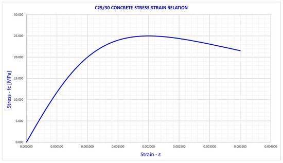
Figure 16.
C25/30 concrete grade stress–strain relation.
The concrete foundation, steel tower, and embedded tower part are suitable for a Hexahedral (Hex) mesh as a geometric shape. The Hex mesh system allows the use of fewer finite elements compared to other mesh systems. In the finite element model created, an eight-point Hex mesh was preferred (Figure 17). The interaction between the embedded tower part and the foundation concrete was modeled by defining friction in the normal and tangential directions between the contact surfaces. The coefficient of friction between concrete and steel elements in the finite element models was assumed to be 0.7 [41]. Smaller sized finite elements (mesh) were used in the contact zones between the embedded tower part and the foundation concrete. The base of the concrete foundation in the finite element models is defined as a built-in support with constraints in all degrees of freedom. A displacement-controlled horizontal load was applied to a reference point connected to the top surface of the steel tower and analyses were performed under cyclic loads. In order to obtain accurate results in finite element analyses, the model must be divided into the correct and sufficient number of finite elements. Convergence analyses were performed on the finite element model and the size and number of finite elements were determined in order to obtain reliable results.
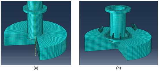
Figure 17.
Finite element mesh models of the test specimens. (a) Reference model and (b) strengthened model.
Cyclic loading analysis performed on the finite element model of the reference specimen resulted in the hysteretic force–displacement and backbone curve (Figure 18).
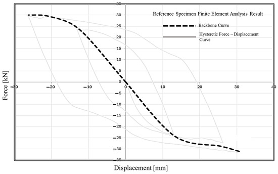
Figure 18.
Hysteretic force–displacement and backbone curves for reference specimen.
The finite element model of the prototype spring-type damper was developed and manufactured to strengthen the tower–foundation connection area prior to the strengthened model finite element analysis was created in ABAQUS [39] software and analyzed. The force–displacement curve obtained as a result of the analysis was found to be consistent with the experimental results (Figure 19).
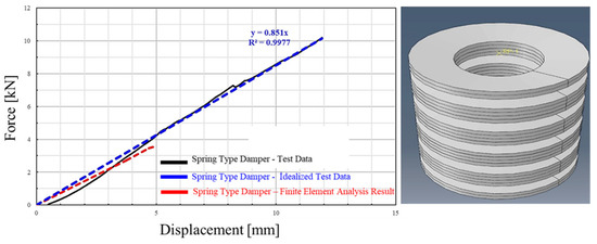
Figure 19.
Spring-type damper test and analysis results.
Cyclic loading analysis performed on the finite element model of the strengthened specimen with a spring-type damper specimen resulted in the hysteretic force–displacement and backbone curve (Figure 20).
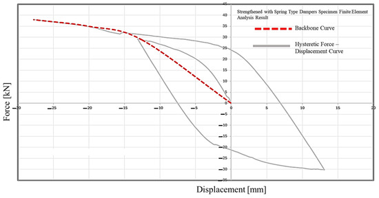
Figure 20.
Hysteretic force–displacement and backbone curves for a specimen strengthened with spring-type dampers.
The force–displacement graphs of the reference and strengthened test specimens obtained from experimental and numerical analyses are shown in Figure 21. To enable a more accurate comparison of experimental and numerical study results, the comparison was performed using backbone curves obtained from hysteresis curves. The backbone curves obtained from the cyclic loading test results for the reference and strengthened specimens were overlaid with the backbone curves obtained from the numerical analysis results, and the results of both studies were compared for both specimens.
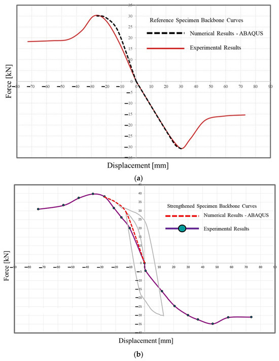
Figure 21.
Experimental and numerical force-displacement backbone curves. (a) Reference model, (b) strengthened model.
It was found that the experimental results and finite element analysis results of the reference and strengthened test specimens were similar.
As a result of the finite element analyses performed for the test specimens formed in 1/15 scale, the stress value of 30 MPa around the base flange (T-Flange) of the reference specimen steel embedded tower part decreased to 13 MPa after the strengthening process (Figure 22). With this applied strengthening method, the stresses around the embedded ring base flange in the foundation (the area where fractures in concrete are most common) were reduced by approximately 57%.
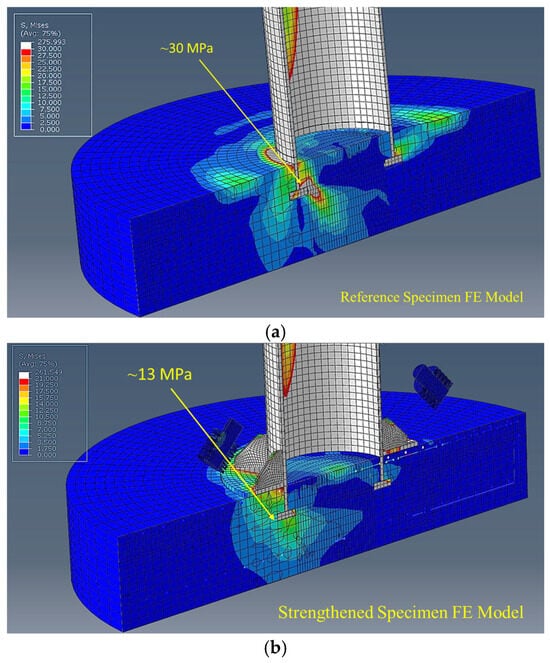
Figure 22.
Finite element analysis results. (a) Reference model and (b) strengthened model (unit, MPa).
4.2. Finite Element Analyses of the Existing Wind Turbine Model
The existing wind turbine foundation was analyzed under design loads, and then the elements in the strengthening method were added to the finite element model, and the analyses were repeated under the same loads, and the improvement in the foundation was determined. A three-dimensional finite element model of the existing wind turbine foundation was created in ABAQUS [39] software (Figure 23). The finite element model consists of a concrete foundation and a steel embedded tower. In the finite element model, an eight-point Hex finite element type was used. The interaction between the embedded tower part and the concrete foundation was modeled by defining friction in the normal and tangential directions between the contact surfaces. The coefficient of friction between concrete and steel elements in the finite element models was assumed to be 0.7 [41]. One-dimensional spring elements representing the soil were defined at the base of the concrete foundation. The existing foundation is circular with a diameter of 16.7 m. The depth of the foundation is 2.53 m, and the embedment depth of the embedded ring in the foundation is 1.58 m. The ratio of the embedment depth to the foundation depth is 0.62. The foundation volume is approximately 650 m3, and the total weight of reinforcement (rebar) in the foundation is 48.47 tones. The total weight of the foundation is 1480 tones. The material class and quality used in the foundation are C25/30 for concrete and S420 for reinforcement. The wind turbine tower is of structural steel grade S355. The existing tower generates electricity with a power of 3 MW, and the tower hub height is 78.33 m. The load values provided by the manufacturer in the tower design are given in Table 3. The loads specified in Table 3 were defined at the junction point (Loading Point) where the loads are transferred to the upper surface of the foundation by the tower, and the analyses were performed.
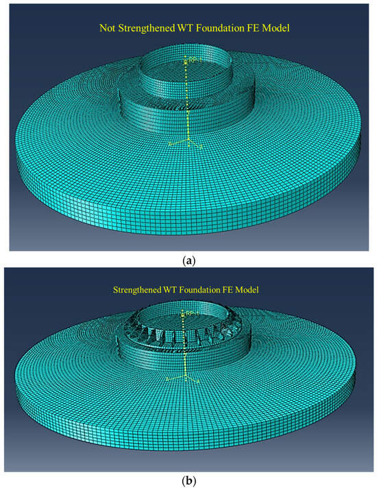
Figure 23.
Wind turbine foundation finite element model. (a) Existing (not strengthened) model and (b) strengthened model.

Table 3.
Foundation design loads.
The tower–foundation joint area was strengthened with spring-type dampers, steel plates, and concrete blocks (Figure 23). The capacity of the spring-type damper to be used in the strengthening process was determined by finite element analyses. Springs with spring coefficients of 1000 kN/mm and 500 kN/mm were selected, and analyses were performed, and the spring capacity to be used for strengthening was determined. In the case of using a 1000 kN/mm capacity spring, 383 MPa stress occurs on the tower steel, and this stress is above 355 MPa, which is the yield strength of the steel. The spring damper with 1000 kN/mm capacity showed rigid behavior and caused the steel to flow by creating large stresses in the tower wall to which it was connected. In the case of a 500 kN/mm capacity spring, 202 MPa stress occurs on the tower steel, and this stress is below 355 MPa, which is the yield strength of steel. It was decided to use spring dampers with a capacity of 500 kN/mm in the strengthening application.
The maximum stress on the concrete block used in the strengthening process was determined to be 48 MPa as a result of finite element analyses. Considering these results, it was concluded that the concrete strength to be used for this region should be at least C50/60 class and above. The maximum stress on the steel plates that will provide the connection between the spring-type dampers and the tower was determined to be 335 MPa. The structural steel to be used for these zones should be S355 class and above. As a result of the finite element studies, the stress values of 12 MPa around the base flange (T-Flange) of the steel embedded tower part in the existing condition (unreinforced condition) decreased to 4 MPa after the strengthening process (Figure 24). With this strengthening method, the stresses around the ring base flange embedded in the foundation (the region where fractures in concrete are most common) were reduced by approximately 67%.
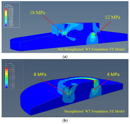
Figure 24.
Von Mises stresses. (a) Existing (not strengthened) model and (b) strengthened model. (unit, MPa).
As a result of the finite element studies, it was determined that the strengthening method developed for wind turbines with an embedded ring tower–foundation connection type reduced the stresses in the foundation by 67%.
5. Conclusions
In recent years, it is known that wind turbine foundations utilizing the embedded ring–foundation connection system from various wind energy facilities around the world have been damaged. The present study investigates the effect of the strengthening method developed using spring-type dampers on the structural behavior of the embedded ring-foundation connection of the wind turbine foundation using experimental and analytical methods.
The improvement effect of the spring-type dampers developed for the strengthening of wind turbine foundations with embedded ring connection type on wind turbine models created in 1/15 scale was investigated by laboratory tests. In addition, the method of filling the voids by injection, which is frequently preferred to repair/strengthen the existing wind turbine tower–foundation connection, was applied to the damaged reference specimen, and then the tests were repeated, and the effect of the repairing/reinforcement process on the foundation was also investigated. Two identical 1/15 scale models of an existing wind turbine were fabricated, a reference and a spring-type damper-strengthened model. Prior to the tests, the spring constant of the spring elements and the characteristic compressive strength of the foundation concrete were determined by laboratory compression tests. Cyclic loading tests were performed on both specimens (reference and spring strengthened) according to the loading procedure specified in ACI 374.1.05 (2005) [38], and the results obtained were evaluated. After the loading tests, the reference specimen was repaired with injection resin and subjected to loading tests again to determine the effect of the injection repairing process. The main contributions and significant findings of this research work are summarized as follows:
The undamaged reference specimen was found to have the lowest initial stiffness value.
The initial stiffnesses of the injection repaired/reinforced reference specimen and the strengthened specimen are approximately 1.25 and 1.31 times higher than the undamaged reference specimen, respectively.
After approximately 2.20% displacement ratio, the reference specimens and injection repaired/strengthened reference specimens showed similar stiffness values.
For all displacement ratios, the stiffness of the specimen strengthened with spring elements is higher than the other two cases.
It was determined that the reference specimen repaired/strengthened by injection application, although initially more rigid than the reference specimen, was the specimen that lost stiffness the fastest for increasing values of displacement ratio.
The reference specimen repaired/strengthened with injection resin reaches the lateral load-carrying capacity earlier compared to the other two cases.
No increase in lateral load-carrying capacity was observed in the repairing/strengthening process with injection resin compared to the reference specimen.
The repairing/strengthening treatment with injection resin enabled the reference specimen to maintain the load-carrying capacity (approximately 20 kN) at the end of the 3.50% drift ratio (i.e., the system can continue to operate from the point where it left off without capacity reduction).
It can be clearly seen from the envelope curves that the repairing/strengthening with injection resin provides additional ductility to the system.
It was determined that the fastest stiffness loss was the reference specimen repaired/strengthened with injection resin.
In the specimen repaired/strengthened with injection resin, no opening and new crack formation were observed in the existing cracks formed in the previous test until 2.75% displacement ratio. When 3.50% displacement ratio was reached, openings were observed in the cracks formed in the previous test and closed by injection.
It was determined that the treatment with injection resin repaired/strengthened the existing cracks, but did not increase the capacity of the system in general.
As shown in the results of cyclic loading tests that the treatments with injection resins, etc., have a repairing/restorative effect on wind turbine foundations rather than strengthening.
The additional lateral resistance (stiffness) provided by the spring elements is much higher than both the reference case lateral resistance and the lateral resistance provided after repairing/strengthening with injection resin.
The specimen strengthened with springs increased the lateral load-carrying capacity by about 33% compared to the reference specimen, and the value of the displacement ratio at which the load-carrying capacity was reached was shifted from 1.40% to 1.75%. This shows that the springs contribute positively to the ductility of the system.
As a result of the cyclic loading tests, it was determined that the strengthening method developed by using spring elements increased the stiffness, ductility and load-carrying capacity of the system.
The improvement effect of the method developed for the strengthening of wind turbine foundations with an embedded ring connection type on the foundation was investigated by finite element analyses. The test specimens were modeled in 1/15 scale and the finite element model was verified according to the structural parameters obtained as a result of the tests. Then, an existing wind turbine foundation with an embedded ring tower—foundation connection was modeled, and the effect of the developed strengthening method on an existing wind turbine foundation was numerically investigated. It was observed that the force–displacement values obtained as a result of the finite element analyses for the test specimens strengthened using reference and spring elements were consistent with the force–displacement values obtained as a result of the experimental studies. This shows that the finite element models created in detail simulate/represent the actual behavior. A finite element model of the foundation of an existing wind turbine (a 1/1 scale wind turbine) with an embedded ring in the tower–foundation connection was created and analyzed. As a result of the analyses, it was determined that the compressive stresses around the embedded ring base flange exceeded the compressive strength of the concrete, and the concrete fractured. The capacity of the spring elements to be used in the strengthening process for the existing wind turbine was determined by performing finite element analyses, and then the developed strengthening method was added to the finite element model, and the analyses were repeated. As a result of the analyses, it was determined that the developed strengthening method reduced the stresses around the embedded ring base flange (the region where fractures in concrete are most common) by 67%, changed the stress distribution in the foundation, and increased the load-carrying capacity of the system by more than 100%. As a result of the finite element studies, it was found that the strengthening method developed for wind turbines with an embedded ring tower–foundation connection type works efficiently and is applicable.
This study demonstrates through testing that the repair methods commonly used in wind turbines with damaged tower–foundation connection regions (cement grout injection, insulation renewal, etc.) repair rather than strengthen the foundation. These applications do not increase the capacity of the foundation but ensure the preservation of the existing capacity. Although these applications repair existing cracks, they cannot prevent the formation of new cracks. The proposed method has been shown to increase the capacity of the foundation and the ductility of the system through laboratory tests and numerical studies.
The proposed method and the latest methods (e.g., circumferential prestressing, dowels) are compared in the following points: (i) The proposed method can be applied more quickly than the latest methods. This reduces the time the wind turbine spends outside of operational status, thereby increasing energy production efficiency. (ii) The latest methods generally aim to strengthen the tower–foundation joint region by proposing applications that increase the embedment length of the embedded ring and prevent foundation uplift (e.g., post-tensioning, etc.). The proposed method both strengthens the tower–foundation joint region and improves the structural behavior of the tower, thereby preventing its collapse. (iii) Recent methods aim to strengthen the tower–foundation joint region. The proposed method both strengthens the tower–foundation joint region and provides the system with additional load-carrying capacity and increased ductility. (iv) Since the capacities of the spring-type dampers in the proposed method are adjustable, they can be easily used for wind turbines of any size. (v) The proposed method was developed based on wind turbines with structural problems in the embedded ring tower–foundation connection, but it is applicable to all existing wind turbines.
The proposed method improves the compressive stress distribution between the embedded steel ring and the reinforced concrete foundation and increases the structure to the desired performance level. In addition, by changing the force transfer mechanism between the embedded ring and concrete, it will close the cracks and prevent the formation of new cracks in the concrete. This method will provide the ability to withstand the stresses caused by service loads by preventing cracking of the concrete and then the fatigue life of the concrete will be increased as the cyclic stress amplitude is reduced.
6. Future Work
The strengthening method developed using spring-type dampers for wind turbine foundations with embedded ring tower–foundation connections, and for which prototype tests have been completed at a scale of 1:15, will be applied to an existing wind turbine (1:1 scale) in the future. Structural health monitoring studies will be conducted on the wind turbine before and after the strengthening application, and the improvement status before and after strengthening will be demonstrated with numerical data. The funding required to carry out this study was secured thanks to the results obtained from laboratory studies conducted at a 1:15 scale. Thus, the improvement effect of the developed strengthening method will be obtained through an existing wind turbine.
Author Contributions
Conceptualization, M.G. and A.N.; methodology, M.G. and A.N.; experimental test, M.G. and A.N.; analysis, M.G.; investigation A.N.; writing—original draft preparation, M.G.; writing—review and editing, A.N.; visualization, M.G.; supervision, A.N. All authors have read and agreed to the published version of the manuscript.
Funding
This research received no external funding.
Data Availability Statement
The datasets presented in this article are not readily available because the data are part of ongoing studies. Requests to access the datasets should be directed to the corresponding author.
Acknowledgments
The authors would like to thank GENOSER Structural Engineering Office (IZMIR/TURKEY) for their technical support during the laboratory tests. The authors would also like to thank Emre ERCAN, Construction Technician Recep GÖZTEPE, Recep SUK and Civil Engineer Özgür GİRGİN for their help in test preparations.
Conflicts of Interest
The authors declare no conflicts of interest.
References
- Soares-Ramos, E.P.; De Oliveira-Assis, L.; Sarrias-Mena, R.; Fernández-Ramírez, L.M. Current status and future trends of offshore wind power in Europe. Energy 2020, 202, 117787. [Google Scholar] [CrossRef]
- Borthwick, A.G. Marine renewable energy seascape. Engineering 2016, 2, 69–78. [Google Scholar] [CrossRef]
- Hou, P.; Enevoldsen, P.; Hu, W.; Chen, C.; Chen, Z. Offshore wind farm repowering optimization. Appl. Energy 2017, 208, 834–844. [Google Scholar] [CrossRef]
- Zhang, P.; Li, J.; Gan, Y.; Zhang, J.; Qi, X.; Le, C.; Ding, H. Bearing capacity and load transfer of brace topological in offshore wind turbine jacket structure. Ocean Eng. 2020, 199, 107037. [Google Scholar] [CrossRef]
- Wang, X.; Zeng, X.; Yang, X.; Li, J. Seismic response of offshore wind turbine with hybrid monopile foundation based on centrifuge modelling. Appl. Energy 2019, 235, 1335–1350. [Google Scholar] [CrossRef]
- Global Wind Energy Council. Global Wind Report 2024 R; Global Wind Energy Council: Brussels, Belgium, 2024. [Google Scholar]
- Bai, X.; He, M.; Ma, R.; Huang, D.; Chen, J. Modelling fatigue degradation of the compressive zone of concrete in onshore wind turbine foundations. Constr. Build. Mater. 2017, 132, 425–437. [Google Scholar] [CrossRef]
- Oliveira, G.; Magalhães, F.; Cunha, Á.; Caetano, E. Continuous dynamic monitoring of an onshore wind turbine. Eng. Struct. 2018, 164, 22–39. [Google Scholar] [CrossRef]
- Lee, Y.S.; González, J.A.; Lee, J.H.; Kim, Y.I.; Park, K.C.; Han, S. Structural topology optimization of the transition piece for an offshore wind turbine with jacket foundation. Renew. Energy 2016, 85, 1214–1225. [Google Scholar] [CrossRef]
- Negro, V.; López-Gutiérrez, J.S.; Esteban, M.D.; Matutano, C. Uncertainties in the design of support structures and foundations for offshore wind turbines. Renew. Energy 2014, 63, 125–132. [Google Scholar] [CrossRef]
- Caselowsky, F. Gründungen von Windkraftanlagen Systeme und deren Bemessung. Ph.D. Thesis, Hochschule Neubrandenburg University of Applied Sciences, Neubrandenburg, Germany, 2008. [Google Scholar]
- Mohamed, W.; Austrell, P.E. A comparative study of three onshore wind turbine foundation solutions. Comput. Geotech. 2018, 94, 46–57. [Google Scholar] [CrossRef]
- Guo, Y.; Zhang, P.; Ding, H.; Le, C. Experimental Study on Torsion Resistance of Foundation Ring Land-Based Wind Power Expanded Foundation Scale Model. Appl. Sci. 2020, 16, 5612. [Google Scholar] [CrossRef]
- Jeong, Y.J.; Park, M.S.; Song, S.H.; Kim, J. Numerical evaluation of structural safety for aged onshore wind foundation to extend service life. Appl. Sci. 2020, 10, 4561. [Google Scholar] [CrossRef]
- Currie, M.; Saafi, M.; Tachtatzis, C.; Quail, F. Structural integrity monitoring of onshore wind turbine concrete foundations. Renew. Energy 2015, 83, 1131–1138. [Google Scholar] [CrossRef]
- Currie, M.; Saafi, M.; Tachtatzis, C.; Quail, F. Structural health monitoring for wind turbine foundations. Proc. Inst. Civ. Eng.-Energy 2013, 166, 162–169. [Google Scholar] [CrossRef]
- Hassanzadeh, M. Cracks in Onshore Wind Power Foundations: Causes and Consequences; Elforsk: Stockholm, Sweden, 2012. [Google Scholar]
- Genç, M. Rüzgar Enerji Sektöründe Kule ve Temel Teknolojileri. In Proceedings of the 4. İzmir Rüzgar Sempozyumu ve Sergisi, İzmir, Türkiye, 28–30 October 2017. [Google Scholar]
- Chen, J.; Li, J.; Li, Q.; Feng, Y. Strengthening mechanism of studs for embedded-ring foundation of wind turbine tower. Energies 2021, 14, 710. [Google Scholar] [CrossRef]
- Chen, J.; Xu, Y.; Li, J. Numerical investigation of the strengthening method by circumferential prestressing to improve the fatigue life of embedded-ring concrete foundation for onshore wind turbine tower. Energies 2020, 13, 533. [Google Scholar] [CrossRef]
- Bai, X.; He, M.; Ma, R.; Huang, D. Structural condition monitoring of wind turbine foundations. Proc. Inst. Civ. Eng.-Energy 2017, 170, 116–134. [Google Scholar] [CrossRef]
- Alonso, T.R.; González Dueñas, E. Cracks analysis in onshore wind turbine foundations. In Proceedings of the IABSE Symposium: Engineering for Progress, Nature and People, Madrid, Spain, 3–5 September 2014. [Google Scholar]
- Stavridou, N.; Efthymiou, E.; Baniotopoulos, C.C. Verification of anchoring in foundations of wind turbine towers. Am. J. Eng. Appl. Sci. 2015, 8, 717–729. [Google Scholar] [CrossRef]
- Yonetsu, K.; Fujiyama, C. Low-Cycle Fatigue Failure Mechanism of Wind Turbine Foundation Due To Vibration of Upper Structure. In Proceedings of the Thirteenth East Asia-Pacific Conference on Structural Engineering and Construction (EASEC-13), Sapporo, Japan, 11–13 September 2013. [Google Scholar]
- Maunu, P. Design of Wind Turbine Foundation Slabs. Master’s Thesis, Luleå University of Technology, Luleå, Sweden, 2008. [Google Scholar]
- Guo, Y.; Zhang, P.; Ding, H.; Le, C. Design and verification of the loading system and boundary conditions for wind turbine foundation model experiment. Renew. Energy 2021, 172, 16–33. [Google Scholar] [CrossRef]
- Xu, J.; Chen, K.; Yang, Y.; Zhang, F.; Meng, W.; Zou, W.; Peng, H. Research on the force mechanism of the connection between the foundation ring and the anchor cage ring of the high-altitude onshore wind turbine. J. Phys. Conf. Ser. 2022, 2181, 012053. [Google Scholar] [CrossRef]
- Paulay, T.; Priestley, M.J.N. Seismic Design of Reinforced Concrete and Masonry Buildings, 1st ed.; John Wiley & Sons: Hoboken, NJ, USA, 1992. [Google Scholar]
- Soong, T.T.; Dargush, G.F. Passive Energy Dissipation Systems in Structural Engineering, 1st ed.; John Wiley & Sons: Hoboken, NJ, USA, 1997. [Google Scholar]
- Clough, R.W.; Penzien, J. Dynamics of Structures, 1st ed.; McGraw-Hill: New York, NY, USA, 1993. [Google Scholar]
- Wang, Y.; Zhang, H.; Li, Z. Performance analysis of tuned mass dampers in wind turbine towers. Energies 2021, 14, 7536. [Google Scholar] [CrossRef]
- Zhou, S.; Zhu, H.; Liu, Y. A novel spring-pendulum-pounding tuned mass damper for offshore wind turbines. Eng. Struct. 2022, 267, 114774. [Google Scholar] [CrossRef]
- Kapasakalis, K.A.; Antoniadis, I.A.; Sapountzakis, E.J.; Kampitsis, A.E. Vibration mitigation of wind turbine towers using negative stiffness absorbers. J. Civ. Eng. Constr. 2021, 10, 123–139. [Google Scholar] [CrossRef]
- Amponsah, E.; Wang, Z.; Mantey, S.K. Bending-bearing behaviour of embedded steel ring-foundation connection of onshore wind turbines. Structures 2021, 34, 180–197. [Google Scholar] [CrossRef]
- Fujiyama, C.; Koda, Y.; Sento, N. Evaluation and stability analysis of onshore wind turbine supporting structures. In Stability Control and Reliable Performance of Wind Turbines; IntechOpen: Rijeka, Croatia, 2018; pp. 103–119. [Google Scholar] [CrossRef]
- Lago, B.D.; Flessati, L.; Marveggio, P.; Martinelli, P.; Fraraccio, G.; di Prisco, C.; di Prisco, M. Experimental tests on shallow foundations of onshore wind turbine towers. Struct. Concr. 2022, 23, 2986–3006. [Google Scholar] [CrossRef]
- Martinelli, P.; Flessati, L.; Dal Lago, B.; Fraraccio, G.; di Prisco, C.; di Prisco, M. Role of numerical modelling choices on the structural response of onshore wind turbine shallow foundations. Structures 2022, 37, 442–458. [Google Scholar] [CrossRef]
- ACI CODE-374.1-05; Acceptance Criteria for Moment Frames Based on Structural Testing and Commentary. ACI Committee: Baltimore, MD, USA, 2005.
- ABAQUS. Abaqus, version 6.11; Dassault Systemes Simulia Corporation: Providence, RI, USA, 2011; Available online: https://www.3ds.com/products/simulia/abaqus (accessed on 9 September 2024).
- Mander, J.B.; Priestley, M.J.N.; Park, R. Theoretical stress-strain model for confined concrete. J. Struct. Eng. 1988, 114, 1804–1826. [Google Scholar] [CrossRef]
- TS 500; Betonarme Yapıların Tasarım ve Yapım KurallarıTürk. Standartları Enstitüsü: Ankara, Türkiye, 2000.
Disclaimer/Publisher’s Note: The statements, opinions and data contained in all publications are solely those of the individual author(s) and contributor(s) and not of MDPI and/or the editor(s). MDPI and/or the editor(s) disclaim responsibility for any injury to people or property resulting from any ideas, methods, instructions or products referred to in the content. |
© 2025 by the authors. Licensee MDPI, Basel, Switzerland. This article is an open access article distributed under the terms and conditions of the Creative Commons Attribution (CC BY) license (https://creativecommons.org/licenses/by/4.0/).