1. Introduction
Wearable electronic systems, enabled by miniaturized components and power sources, monitor vital parameters for patients [
1,
2], track training parameters for athletes [
3], and detect hazardous situations for firefighters [
4]. A notable application of these systems is in assisting individuals with disabilities, particularly the visually impaired [
5,
6]. These systems often integrate miniature cameras into user attire, wirelessly transmitting images for the automated or human-assisted detection of obstacles or threats [
7]. Therefore, reliable, high-data-rate wireless transmission is crucial for these image-based systems to effectively identify potential hazards. These premises motivated the development of an antenna suitable for integration into a wireless system designed to support the visually impaired.
Fifth-generation (5G) wireless systems offer a highly promising solution for applications requiring high-data-rate image transmission, primarily due to their inherently low latency. This characteristic is particularly critical for applications involving mobile users, such as assistive technologies designed for the visually impaired. In such scenarios, real-time video streaming is essential for detecting potentially hazardous situations; consequently, any significant delay in data delivery or loss of transmission can lead to a critical loss of tracking, thereby creating dangerous circumstances for the user.
To thoroughly evaluate a prototype system developed at Łódź University of Technology (TUL) [
5,
6,
7] for this specific purpose, a private 5G network is currently being utilized for image transmission. TUL’s campus is home to a dedicated 5G research network and a 5G Competence Center, both established under the Digital Innovation Hub 5G initiative [
8]. This state-of-the-art infrastructure significantly facilitates advanced research and innovation in nascent 5G technologies. The network’s radio access operates across two distinct frequency bands: the 700 MHz band, primarily for 4G connectivity and Internet of Things (IoT) applications, and the 3.5 GHz band, dedicated to high-data-rate 5G transmissions. This dual-band configuration makes the network exceptionally well-suited for meeting the demanding requirements of image-based assistive systems, ensuring both robust connectivity and high-throughput data transfer. The availability of this 5G campus network, particularly its 3.5 GHz band, directly motivated the antenna design described in this paper.
The 3.5 GHz band (3400–3800 MHz) has become a foundational element for 5G deployments worldwide [
9,
10]. Its optimal balance of coverage and capacity is essential for delivering enhanced mobile broadband services. In Europe, the European Commission and CEPT have spearheaded harmonization efforts, designating this spectrum as a primary pioneer band for 5G. This has led to widespread licensing and initial rollouts by national regulatory authorities across the continent. Globally, more than 60 countries have allocated portions of the 3.5 GHz range for their 5G networks, with many in Asia and Latin America assigning substantial bandwidths to mobile operators. While this mid-band spectrum has been crucial to 5G’s early success, some regional challenges persist. For instance, in the US, the Citizens Broadband Radio Service (CBRS) implements a tiered access system. In Europe, ongoing efforts focus on cross-border coordination and expanding the spectrum beyond 3.8 GHz for future 5G advancements.
An antenna designed for the 3.5 GHz band is highly compatible with numerous 5G networks globally. This stems from the band’s widespread harmonization and its ideal characteristics for 5G. Often referred to as a C-band or n78 in 3GPP standards, the 3.5 GHz range strikes a crucial balance between coverage and capacity. This allows for the deployment of robust 5G services that can penetrate buildings and cover substantial areas while delivering high speeds. This widespread adoption is a direct result of international efforts, particularly by the ITU and regional bodies such as CEPT, to identify and allocate this spectrum as a priority for 5G, fostering a largely unified ecosystem for equipment and device manufacturers.
While 5G systems operating in the 3.5 GHz band offer substantial bandwidths, their indoor penetration is often hampered by signal attenuation caused by building structures. In such cases, the campus Wi-Fi network becomes a crucial alternative. The campus Wi-Fi primarily utilizes the 2.4 GHz and 5.8 GHz bands. The 2.4 GHz band, despite its widespread availability, presents several challenges for stable data transmission. It offers lower data throughput compared to higher frequency bands and is highly susceptible to interference [
11]. This susceptibility, coupled with increased contention in the shared spectrum and the inherent limitations of lower-frequency bands, exacerbates congestion and retransmissions, significantly impacting latency stability. Conversely, the 5.8 GHz Wi-Fi band offers a viable and often superior alternative. It provides higher data rates and demonstrates greater resilience to interference. This makes the 5.8 GHz band a compelling choice for scenarios requiring both high bandwidth and widespread accessibility, effectively complementing the limitations of 5G indoor coverage and the drawbacks of the 2.4 GHz band.
For these reasons, the design of an antenna operating in both the 3.5 GHz and 5.8 GHz bands was adopted as a primary objective. Considering the requirement for systems assisting the visually impaired to transmit images representing the monitored person’s surroundings, it was posited that the camera, transmitter, and antenna would be integrated with eyeglasses.
Antennas integrated into eyeglasses have been widely reported in the literature. In [
12], a transparent and flexible monopole antenna for a single 2.4 GHz band is presented, fabricated with physical vapor deposition technology on the glass surface. In [
13], researchers studied a slot loop antenna made from a transparent metal-mesh film and a metallic glass frame, also for the 2.4 GHz band. In both cases, the design implementation poses significant technological challenges due to the materials employed. The antenna described in [
14] comprises two planar inverted F antennas operating in a single band (2.4 GHz), resulting in a relatively large configuration requiring space on both sides of the glasses. The antenna presented in [
15] is designed for 4G and 5G frequencies. It is a multi-port antenna system that consists of two antennas for 4G communication arranged on two glasses frames, and four antennas for 5G communication arranged on two glasses legs. This set of antennas has a very complex design, including matching circuits at each port, and requires an electrical connection to arbitrarily shaped multiloops surrounding the lenses, necessitating a redesign of the entire eyewear structure. This design covers 0.824–0.96 GHz and 1.71–2.69 GHz for one port and two 5G bands of 3.3–3.6 GHz and 4.8–5.0 GHz at another input. The recent antenna design presented in [
16] covers two bands of the Wi-Fi standard: 2.4 GHz and 5.8 GHz. The radiator is based on an inverted T geometry and was fabricated with a dielectric substrate with two layers of metallization. Another design, presented in [
17], introduces a compact 6 × 6 MIMO antenna system integrated into glasses, designed for Wi-Fi 6E and Wi-Fi 7, featuring six F-shaped monopole antennas. It allows dual-band operation at 2.45 GHz and 5.5 GHz, achieving high efficiency and gain at both frequencies. This is an extension of the previously developed four-antenna system that has frequency bandwidths at 4.58–5.72 GHz and 6.38–7.0 GHz [
18]. The antenna presented in [
19] is a compact 2 × 2 on-chip microstrip antenna array that operates in the W-band (76.11–83.87 GHz) with a gain of over 10 dBi, making it ideal for integration into smart glasses. Its low-loss glass substrate and embedded feeding structure provide a cost-effective, high-performance solution for advanced communication in a wearable form.
Table 1 presents the bands and technologies of glass-integrated antennas reported in the literature.
This paper addresses a critical research gap: the development of a low-profile antenna capable of dual-band operation at 3.5 GHz and 5.8 GHz, specifically designed for seamless integration into eyeglasses. Our design approach centers on creating an antenna that can be incorporated into the existing structure of standard glasses without necessitating fundamental alterations to their construction. Given that the intended application involves a wireless camera system positioned at the front of the eyeglasses, the antenna must be specifically contoured to fit discreetly within the temple of the glasses. This particular integration challenge forms the core of the research presented in this paper. Our objective is to contribute a novel antenna design that not only meets these stringent dimensional and operational requirements but also ensures efficient and reliable data transmission for advanced assistive devices aimed at the visually impaired.
2. Materials and Methods
This research work elucidates the antenna design and the methodology employed in its research. It begins with a thorough exposition of the design specifications and the presentation of the preliminary design that did not meet the requirements. Then, the final design is presented. Given the reliance on computer simulations, the corresponding results are also detailed within this section.
2.1. Antenna Design—Assumptions
The primary objective of this project was the development of a dual-band antenna suitable for integration with eyewear. A key requirement was the non-destructive attachment of the antenna to existing spectacles, necessitating its placement on the temples. The height of the antenna should not exceed 14 mm, and its length should not be greater than 85 mm. The antenna’s thickness should be less than 5 mm. This application demands a compact and lightweight antenna exhibiting satisfactory impedance matching and a potentially high gain, despite its proximity to the human body. To achieve these characteristics, a viable geometric configuration amenable to fabrication using thin-layer laminate technology with single-sided metallization was investigated.
2.2. Preliminary Design
The antenna design was developed through numerical simulations, employing the Remcom XFdtd version 7.9 electromagnetic simulation software [
20,
21]. This software utilizes the finite difference time domain (FDTD) method, which is inherently capable of handling objects composed of diverse materials and has been successfully applied to model the complex electromagnetic properties of the human body.
The initial antenna design employed an inverted F antenna (IFA) geometry. Due to design constraints, its dimensions were limited to a maximum of 14 by 82 mm. Consequently, the remaining antenna dimensions and the position of the feed point served as the primary degrees of freedom. These dimensions were iteratively adjusted to achieve optimal impedance matching within the targeted bands of 3.5 GHz and 5.8 GHz. However, given that the inverted F antenna is not inherently dual-band, it proved impossible to optimize its dimensions to meet the specified design goals.
Figure 1 illustrates the dimensions of the antenna that exhibited the closest impedance matching performance to the desired specifications. It was first designed for a free space environment; however, even for this relaxed requirement, the design goal was not met.
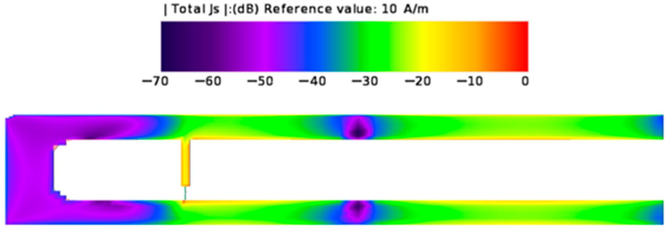
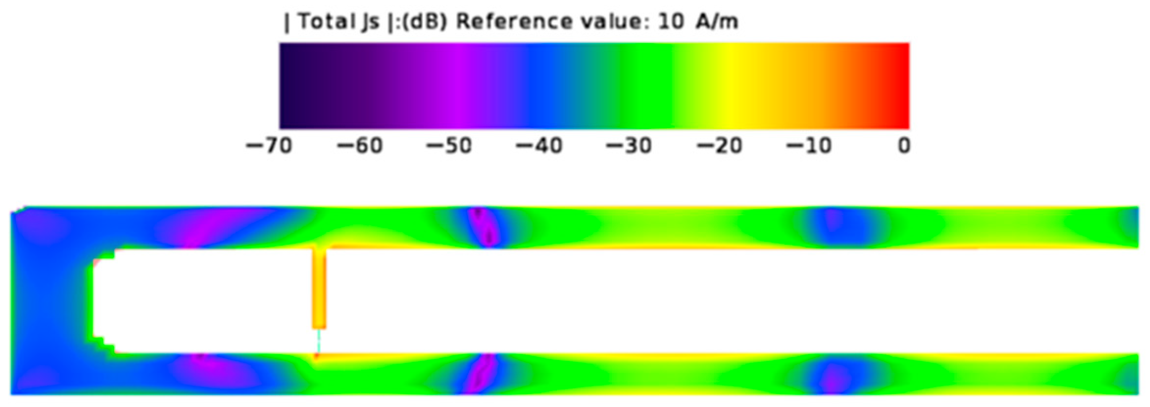
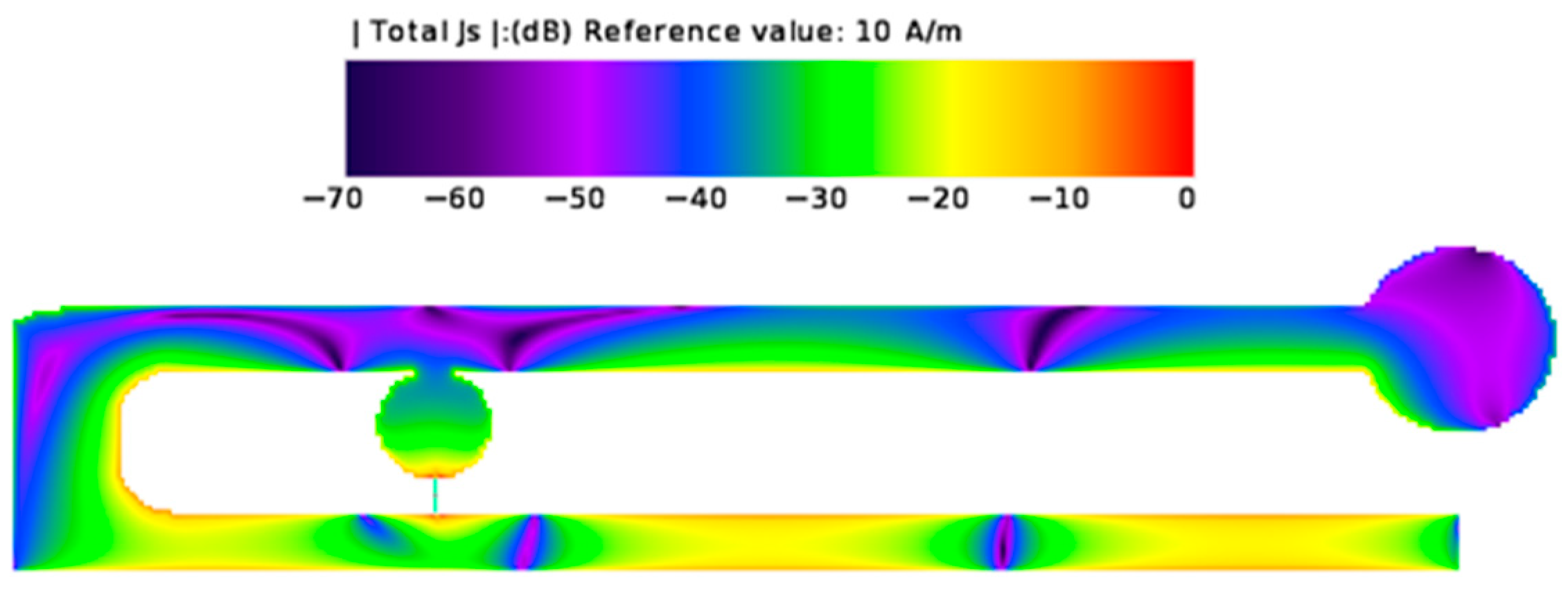
Figure 2 presents the current distribution on the antenna surface for 3.5 GHz, and
Figure 3 shows this for 5.8 GHz. The simulated impedance matching results for this antenna are presented in
Figure 4. The voltage standing wave ratio (VSWR) minima occurred at frequencies of 3.5 GHz and 5.6 GHz. For the first band, a significant mismatch was observed, with a VSWR of 2.7. While the impedance matching for the second band was improved (VSWR = 1.7), the frequency of optimal matching did not align with the intended specification. Therefore, a modification of the original F-type antenna structure was deemed necessary, and this revised design will be detailed in the subsequent sections of this article.
2.3. Final Design—Modified IFA
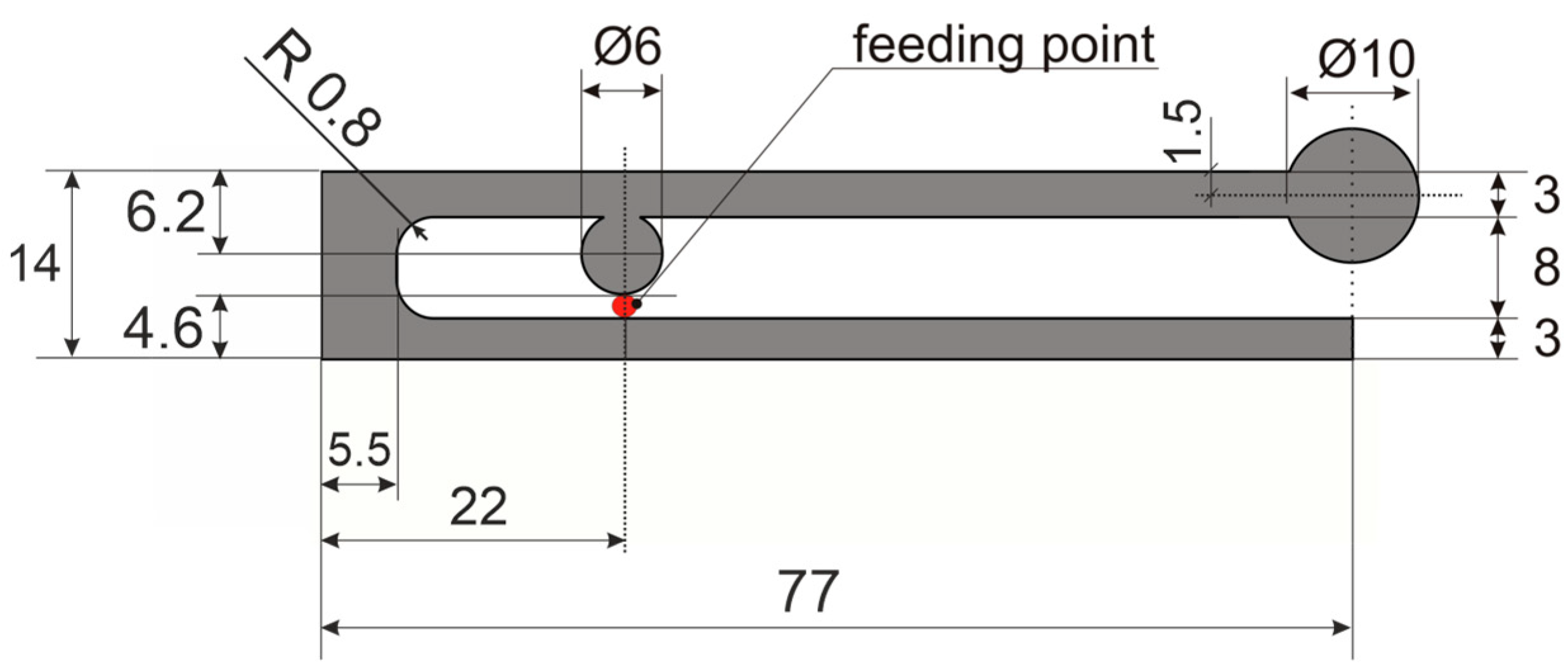
The antenna discussed in this paper is a modified inverted F antenna (IFA), with its unique geometry detailed in
Figure 5. Unlike conventional IFAs, this design significantly enhances performance by incorporating circular elements at both the feed point and the radiating arm’s terminus.
These circular elements were introduced to facilitate dual-band operation at 3.5 GHz and 5.8 GHz. Through an iterative optimization process, the antenna’s dimensions were precisely determined to achieve optimal impedance matching across these frequency bands, considering both free-space and near-head operational scenarios. This design also maintains a compact form factor, with a diminutive height of 14 mm and a width of 77 mm, making it highly suitable for integration into eyewear temples. The simulation assumed a conductor thickness of 0.1 mm.
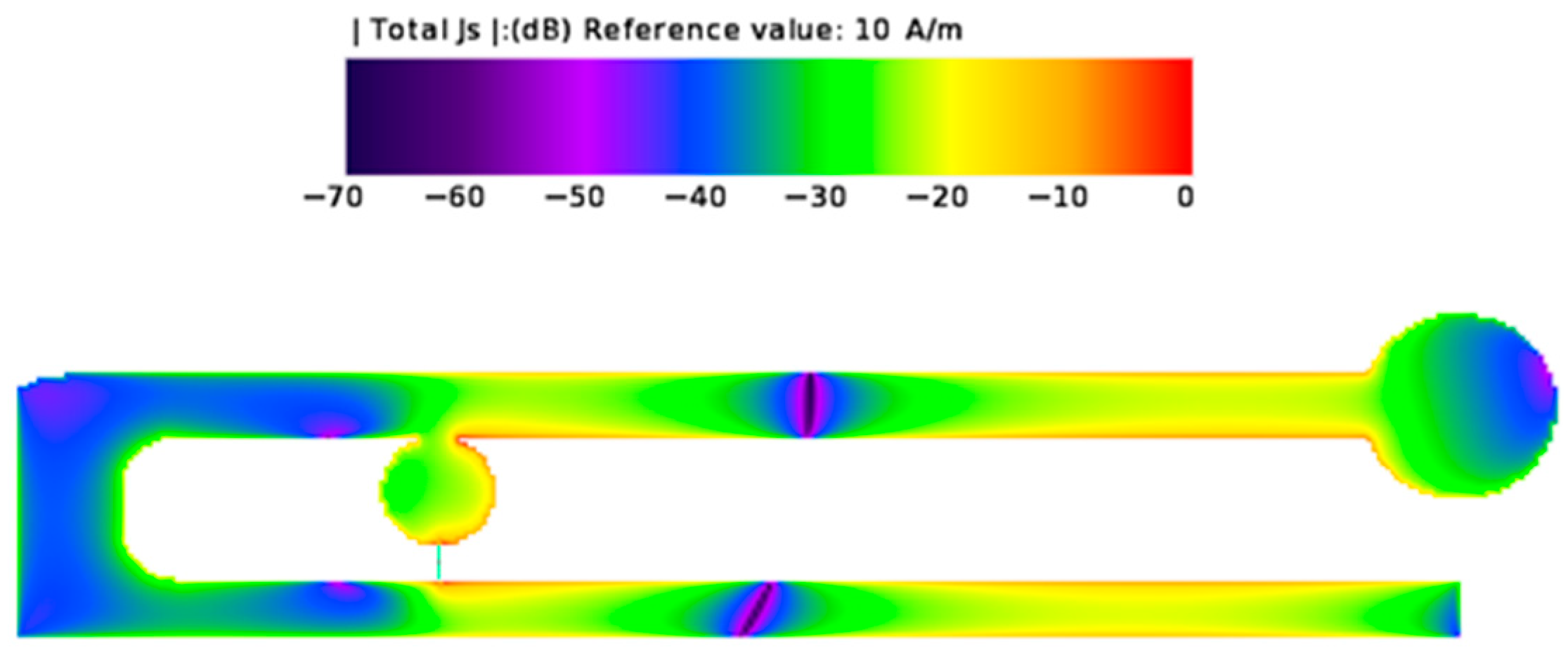
A key advantage of integrating these circular elements is the resultant greater current values within the 3.5 GHz and 5.8 GHz bands. This increase in current directly translates to improved radiation efficiency and overall antenna performance at these critical frequencies. The current distribution patterns for 3.5 GHz and 5.8 GHz are visually represented in
Figure 6 and
Figure 7, respectively, clearly demonstrating these enhanced current values.
2.4. Antenna Design—Computer Simulations
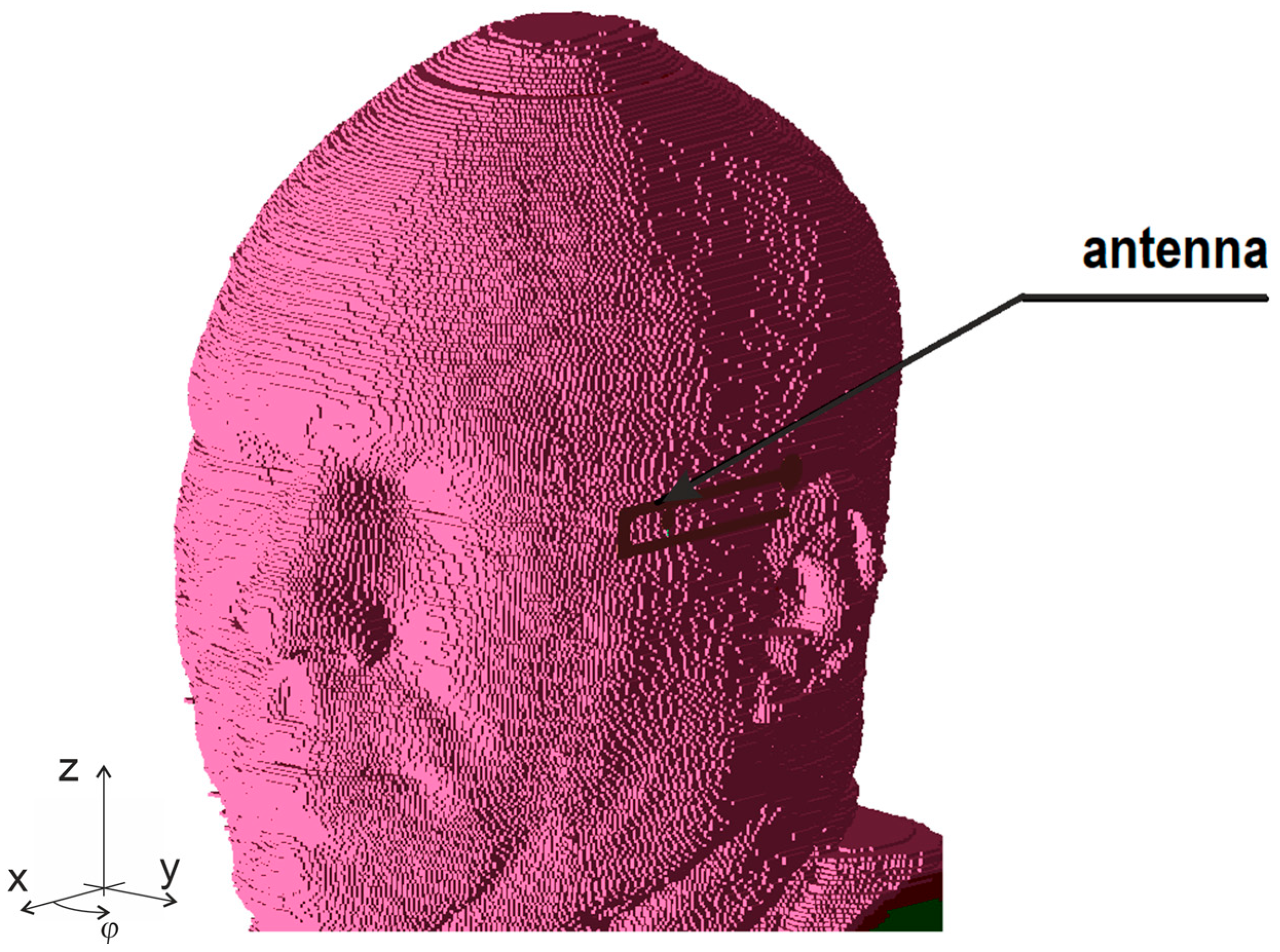
The FDTD method that is implemented in the XFdtd software version 7.9 used in this research facilitates the accurate simulation of the interaction between the antenna and the human body, particularly in near-field scenarios relevant to this application. The numerical model depicting the antenna positioned on the head, corresponding to the temples of eyeglasses, is presented in
Figure 8. In this configuration, the antenna is situated at a distance of 8 mm from the surface of the head. For the simulations, the heterogeneous human head model available in the XFdtd software was used, with an elementary cell size of 1 mm.
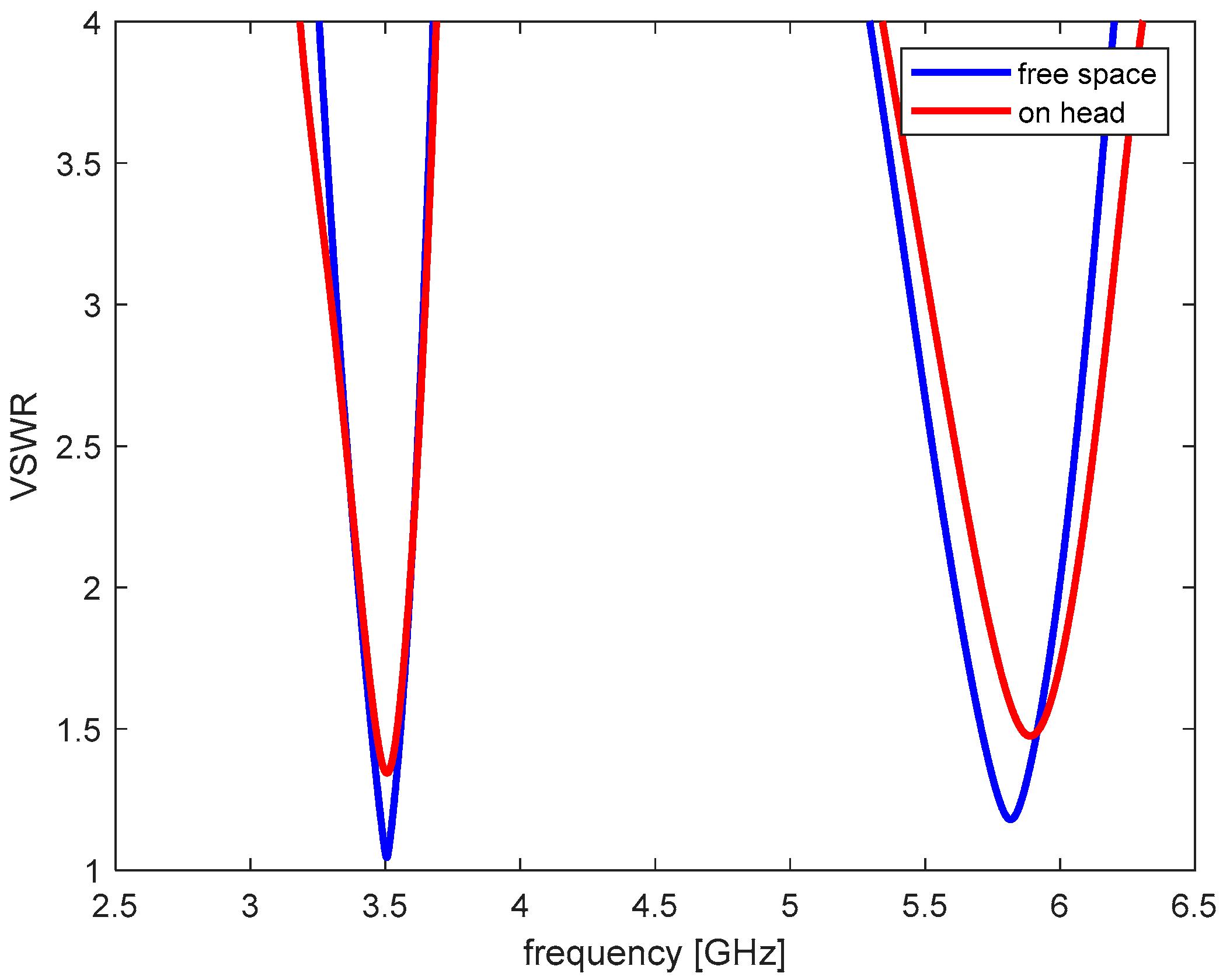
The antenna’s impedance matching characteristics, expressed as the voltage standing wave ratio (VSWR) with respect to a 50 Ω reference impedance, are depicted in
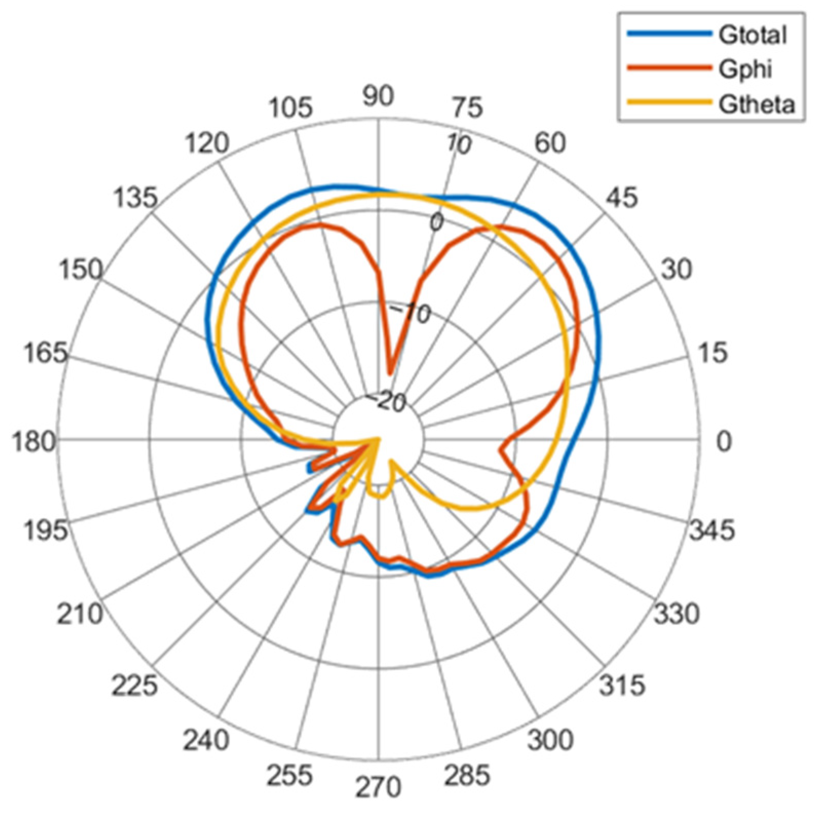
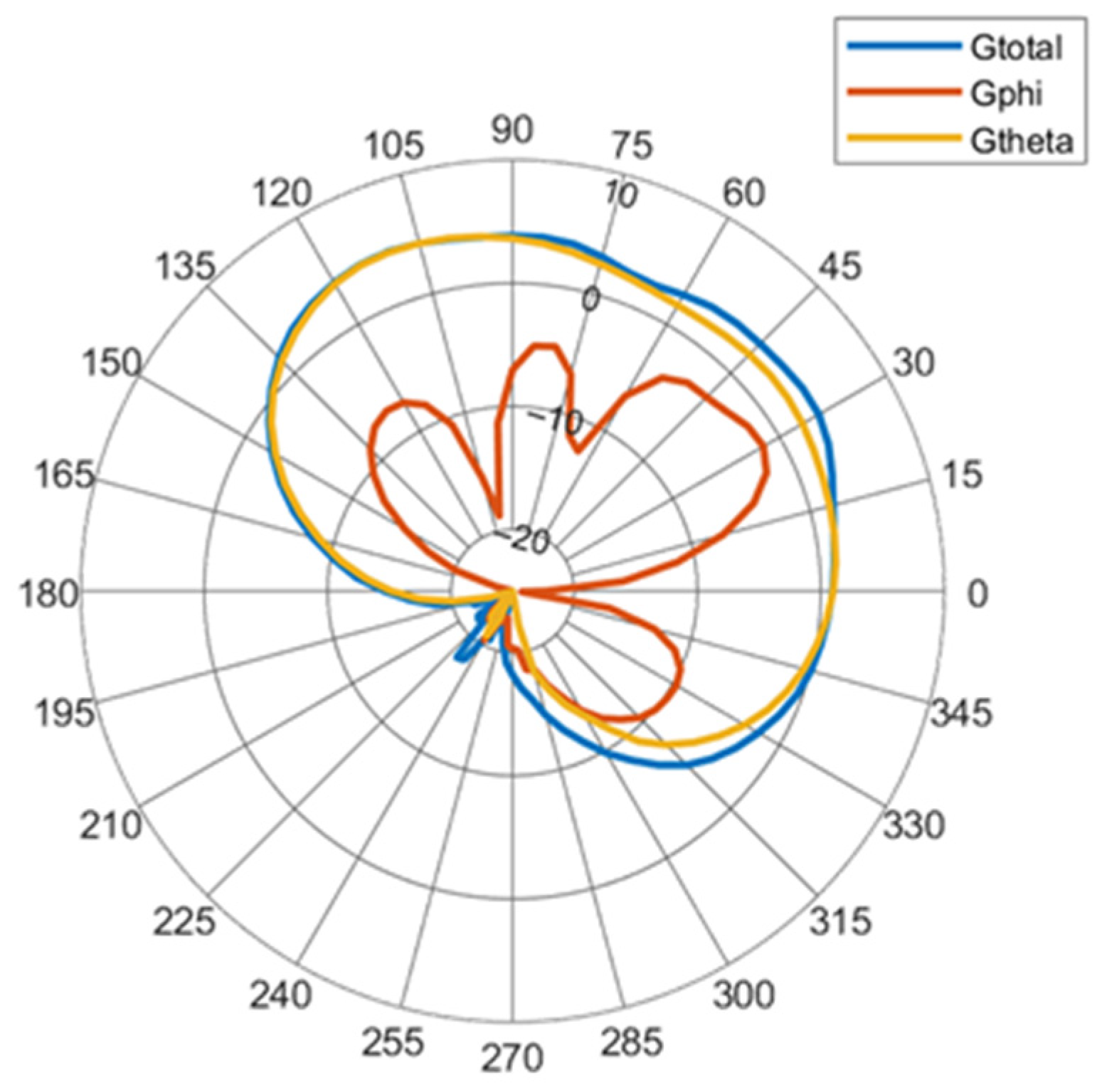
Figure 9. A VSWR of ≤2 defines the impedance bandwidth, which spans 3.4 GHz to 3.6 GHz in free space and remains consistent when positioned on the human body. In the higher band, the proximity of the human head introduces a minor impedance detuning. Nevertheless, the impedance bandwidth in the free space extends from 5.61 GHz to 6 GHz, and for on-head placement, it ranges from 5.7 GHz to 6.05 GHz, effectively encompassing the target frequency bands in both scenarios. The simulated radiation patterns in the horizontal plane (x-y plane as defined in
Figure 8) are presented in
Figure 10 for 3.5 GHz and in
Figure 11 for 5.8 GHz. For 3.5 GHz, the total gain of the antenna was
Gtotal = 4.8 dBi. The component of gain for linear polarization parallel to
φ versor was
Gphi = 2.9 dBi. For
θ,
Gtheta = 1.7 dBi. For 5.8 GHz, the total gain of the antenna was
Gtotal = 4.3 dBi. The component of gain for linear polarization parallel to
φ versor was
Gphi = −1.5 dBi. For
θ,
Gtheta = 4.2 dBi.
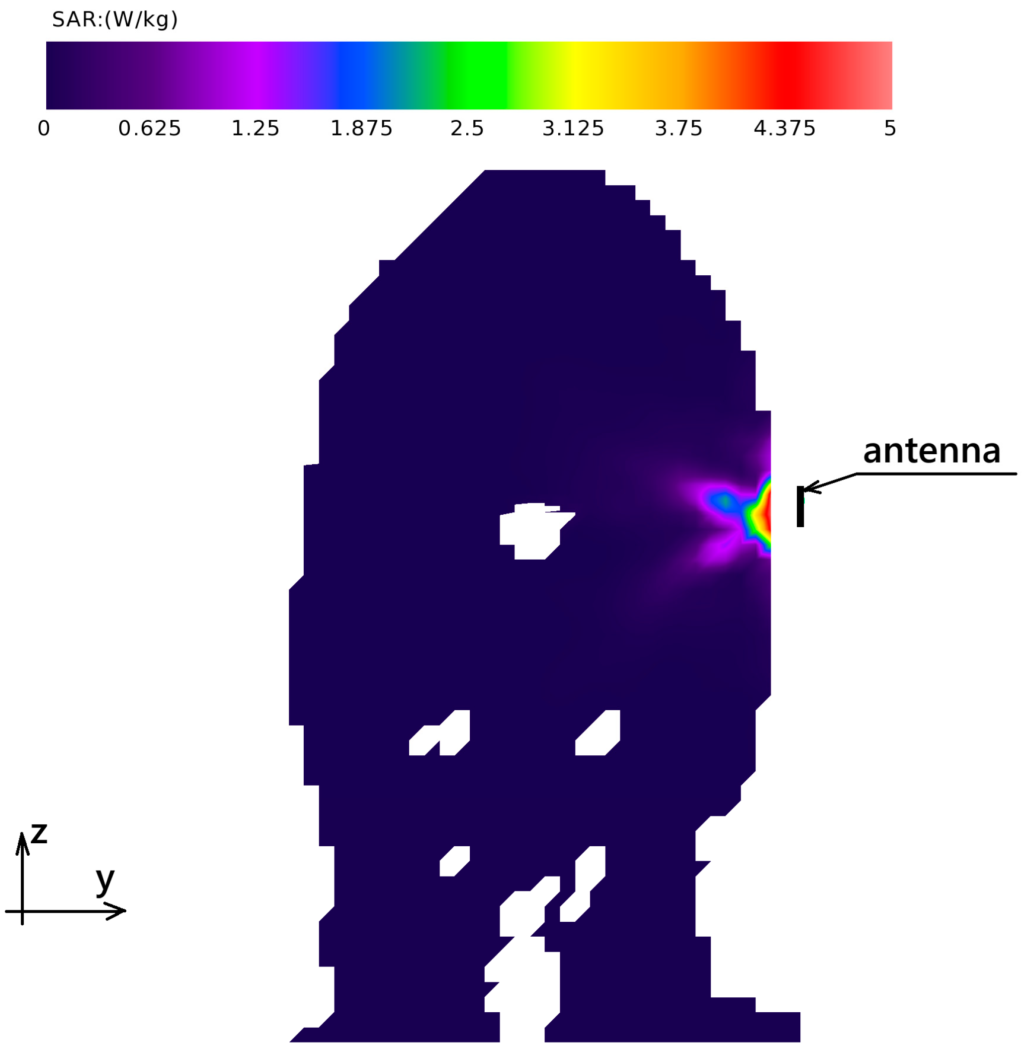
The investigation of the designed antenna’s characteristics was supplemented by an analysis of the energy absorbed by human tissues in close proximity to the antenna. This was achieved through simulations of the specific absorption rate (SAR) parameter. For this purpose, maximum power values for 5G transmitters in the 3.5 GHz band and Wi-Fi in the 5.8 GHz band were assumed.
At a frequency of 3.5 GHz, the power of the transmitter connected to the on-body antenna was set at 250 mW. Under these conditions, the maximum SAR value averaged over 10 g of tissue was 1.8 W/kg, while the maximum value averaged over 1 g of tissue reached 4.8 W/kg. The distribution of the SAR parameter averaged over 1 g of tissue in the z-y plane cross-section, where the highest values occur, is illustrated in
Figure 12. The white areas visible in the SAR distribution result from the averaging of results for volumes containing 1 g of tissue and appear in regions where air is present within the human body, such as the nasal sinuses and larynx.
Similar results were also determined for a frequency of 5.8 GHz. Here, the maximum transmitter power was assumed not to exceed 200 mW, which is typical for the WiFi standard. For this frequency, the maximum SAR value averaged over 10 g of tissue was 0.6 W/kg, and the maximum value averaged over 1 g of tissue was 1.4 W/kg. The distribution of the SAR parameter averaged over 1 g of tissue in the z-y plane cross-section, where the highest values occur, is presented in
Figure 13.
The simulated maximum specific absorption rate (SAR) values for both the 3.5 GHz and 5.8 GHz bands remained below the European Union’s recommended limit of 2.0 W/kg, averaged over 10 g of tissue [
22]. This compliance was demonstrated under the conservative assumption of continuous operation at the maximum permissible power for each respective wireless standard. It is anticipated that under typical operational conditions, where adaptive power control mechanisms are employed, the actual SAR values would be considerably lower.
3. Results—Design Verification with the Antenna Prototype
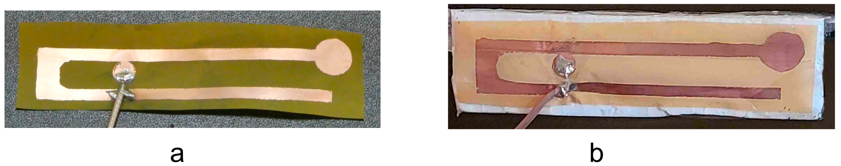
The prototype antenna was fabricated using flexible, single-sided Pyralux laminate from DuPont (Circleville, OH, USA), a material previously employed by the author for flexible wearable antenna development, demonstrating its suitability for rapid prototyping via chemical etching [
23,
24]. The fabricated prototype is depicted in
Figure 14 and is fed via a coaxial probe. Due to the very low thickness of the substrate, the antenna is very flexible and easy to fold. To stabilize the plane shape of the antenna, it was placed on a Styrofoam spacer with a thickness of 5 mm. Due to its low density, this material has electrical properties that are very similar to air and does not introduce an impedance mismatch with the antenna.
For the comprehensive characterization of the antenna, the prototype, equipped with a Styrofoam spacer, was securely attached to plastic protective glasses using adhesive tape. These glasses were then carefully positioned on a human head phantom, ensuring a consistent 9 mm separation between the antenna’s radiating element and the phantom’s surface, as visually depicted in
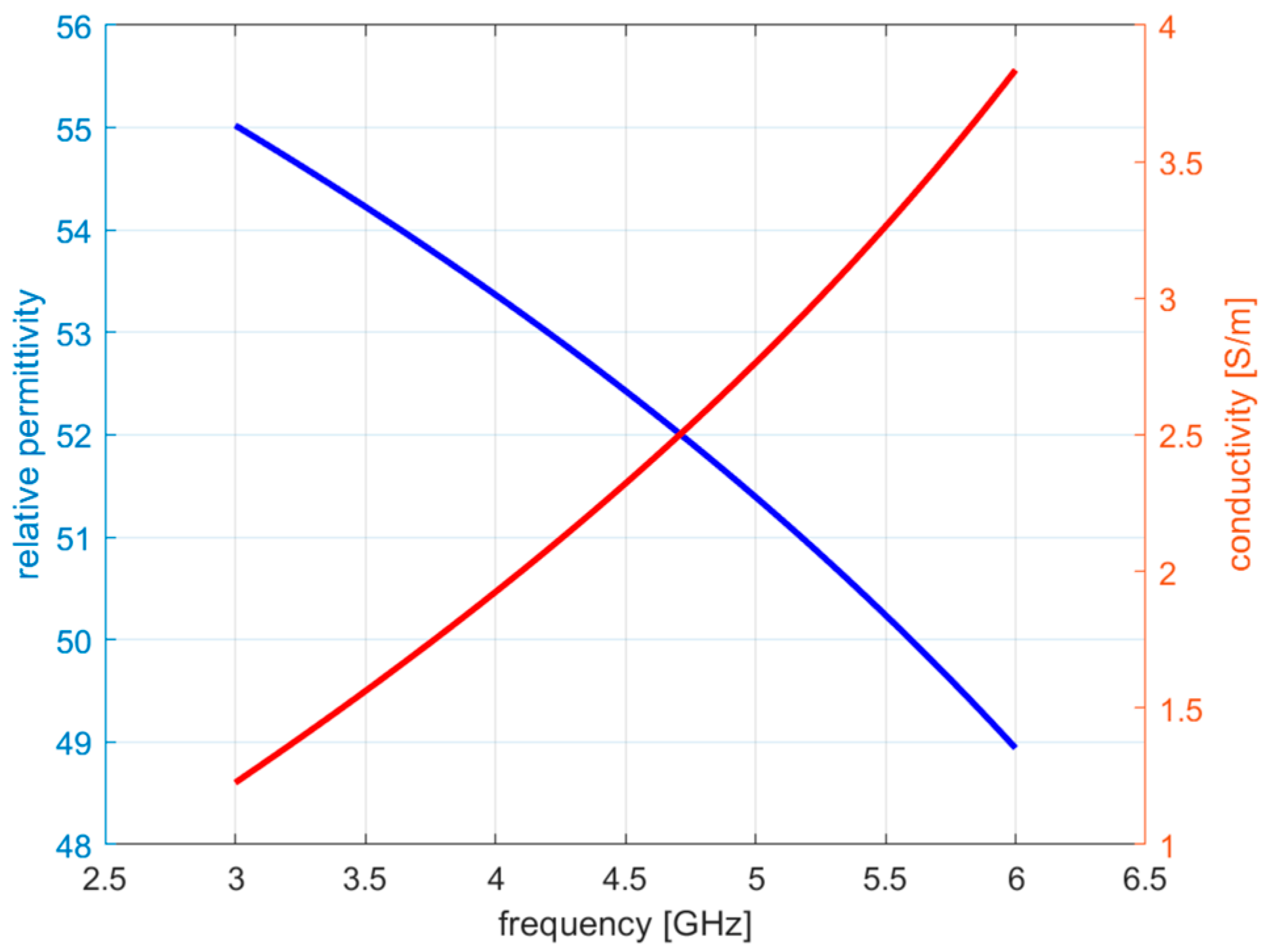
Figure 15. The phantom itself was filled with a meticulously prepared tissue-simulating liquid, engineered to emulate the dielectric properties of human tissue at the operational frequency. This liquid exhibited a relative permittivity of 55 and a conductivity of 1.2 S/m at a frequency of 3 GHz and a temperature of 23 °C.
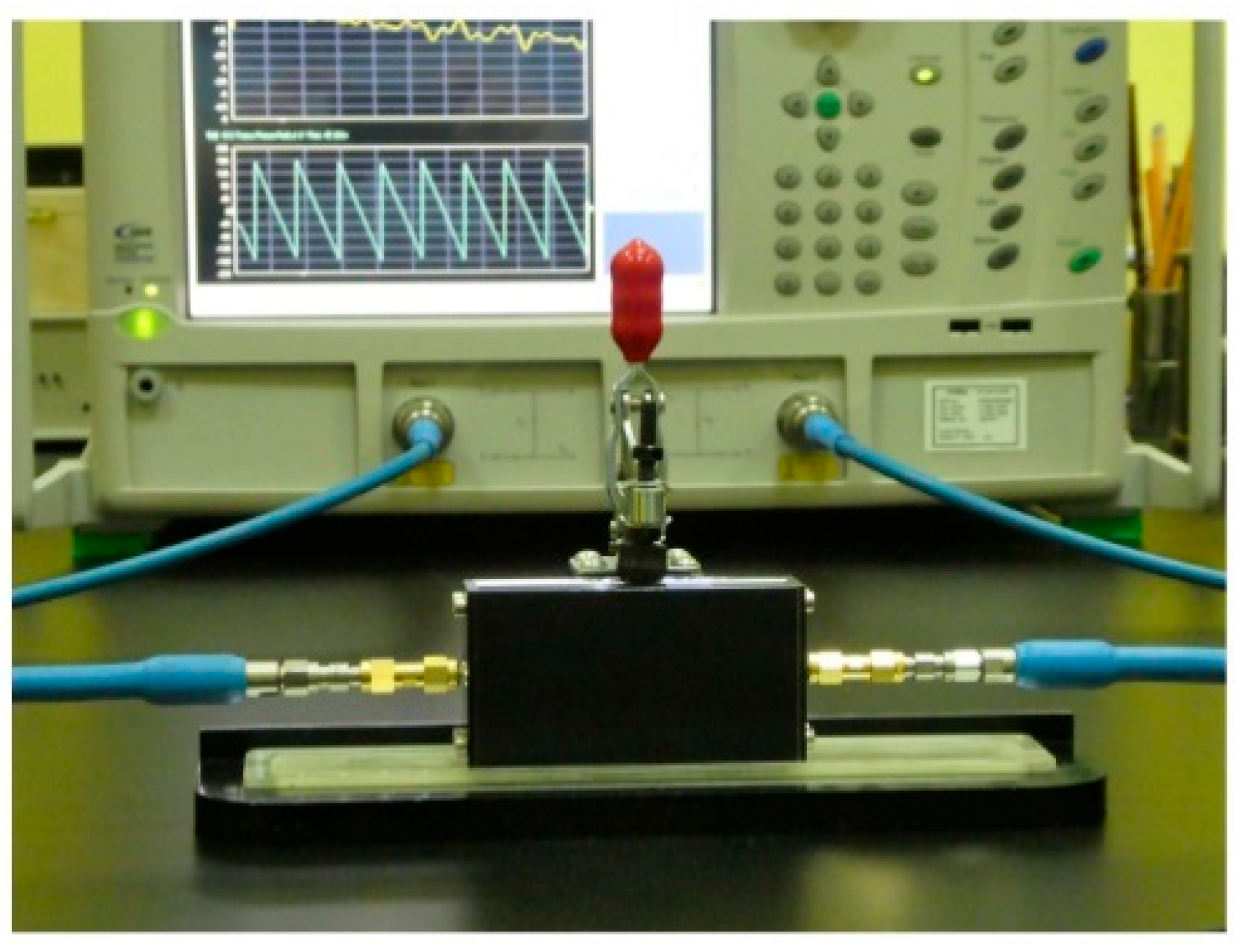
The precise dielectric properties of this tissue-simulating liquid were determined using a Di-line measurement system, as illustrated in
Figure 16. This system has been previously validated and employed by the author for the accurate characterization of liquids utilized in various human body phantom studies, as referenced in [
25,
26,
27]. The characterization results, directly obtained from the Di-Line software version 1.0, are systematically presented in
Figure 17. Notably, the measured values for the liquid’s properties align closely with those reported in the existing literature for comparable tissue-simulant liquid materials [
28], thus validating the fidelity of the phantom’s dielectric representation.
Subsequent measurements of the antenna’s impedance and radiation pattern were rigorously performed within an anechoic chamber to mitigate external electromagnetic interference.
Figure 15 further illustrates the prototype antenna’s mounting on the test stand within this anechoic environment. For radiation pattern measurements, the human head phantom was affixed to a motorized rotor, designed to rotate precisely around a vertical axis. The rotation of this rotor was meticulously controlled by dedicated measurement software, which simultaneously recorded the received power at each angular increment using a FSC6 spectrum analyzer produced by Rohde & Schwarz, Vienna, Austria. This integrated setup allowed for the accurate acquisition of the antenna’s far-field radiation characteristics under conditions closely approximating in situ operation.
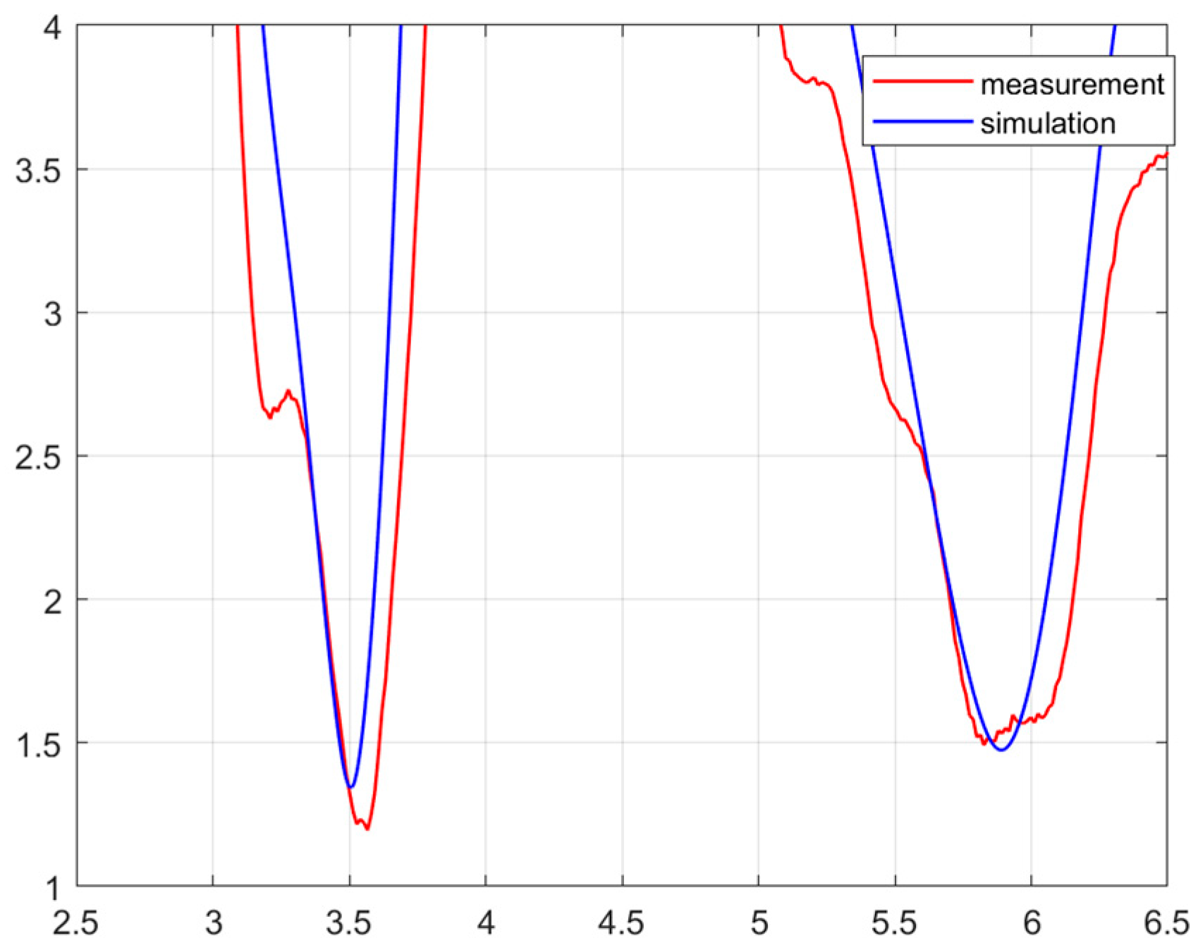
Impedance matching measurements were performed with an MS4647 network analyzer fabricated by Anritsu (Morgan Hill, CA, USA). The calibration plane was moved to the opening of the coaxial probe in the antenna feeding point. The gain measurements were carried out with the Rohde & Schwarz HF 907 antenna, using the reference antenna method for this purpose. The results of the antenna impedance matching measurements are shown in
Figure 18. In this case, the impedance band covers the range from 3.40 GHz to 3.64 GHz and from 5.7 GHz to 6.15 GHz.
The antenna radiation pattern was primarily characterized in the horizontal plane, which is a typical and highly relevant orientation for wearable antennas designed to operate on or in close proximity to the human body. Investigating the radiation characteristics in the vertical plane, however, presents additional complexities. These measurements are inherently influenced by several factors, including the dimensions and type of the ground plane considered, as well as the specific height of the human subject. To ensure direct comparability with numerical simulations, which were also conducted utilizing a human head model, the investigation was specifically focused on the x-y plane. Given that the measurement antenna possessed linear polarization, the radiation pattern was comprehensively measured for both vertical polarization (Gtheta) and horizontal polarization (Gphi).
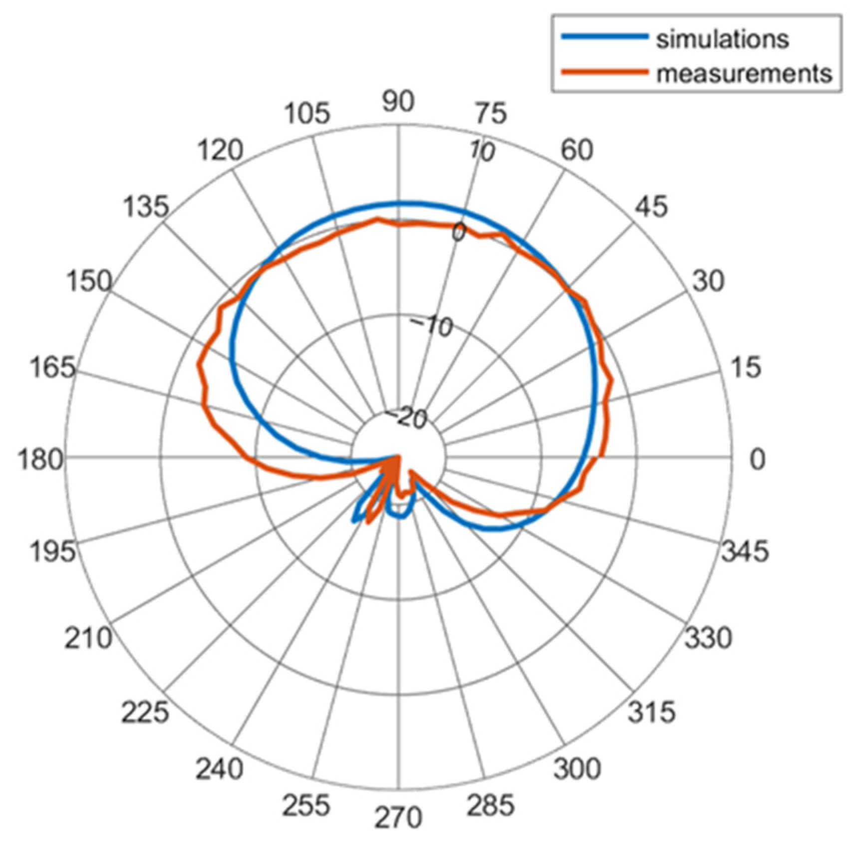
At a frequency of 3.5 GHz, the measured radiation pattern for vertical polarization is presented in
Figure 19. For this specific polarization, the maximum measured gain achieved was 0.85 dBi. Correspondingly, the radiation pattern for the same frequency but with horizontal polarization is detailed in
Figure 20. In this configuration, the maximum measured gain was significantly higher, reaching 3.6 dBi.
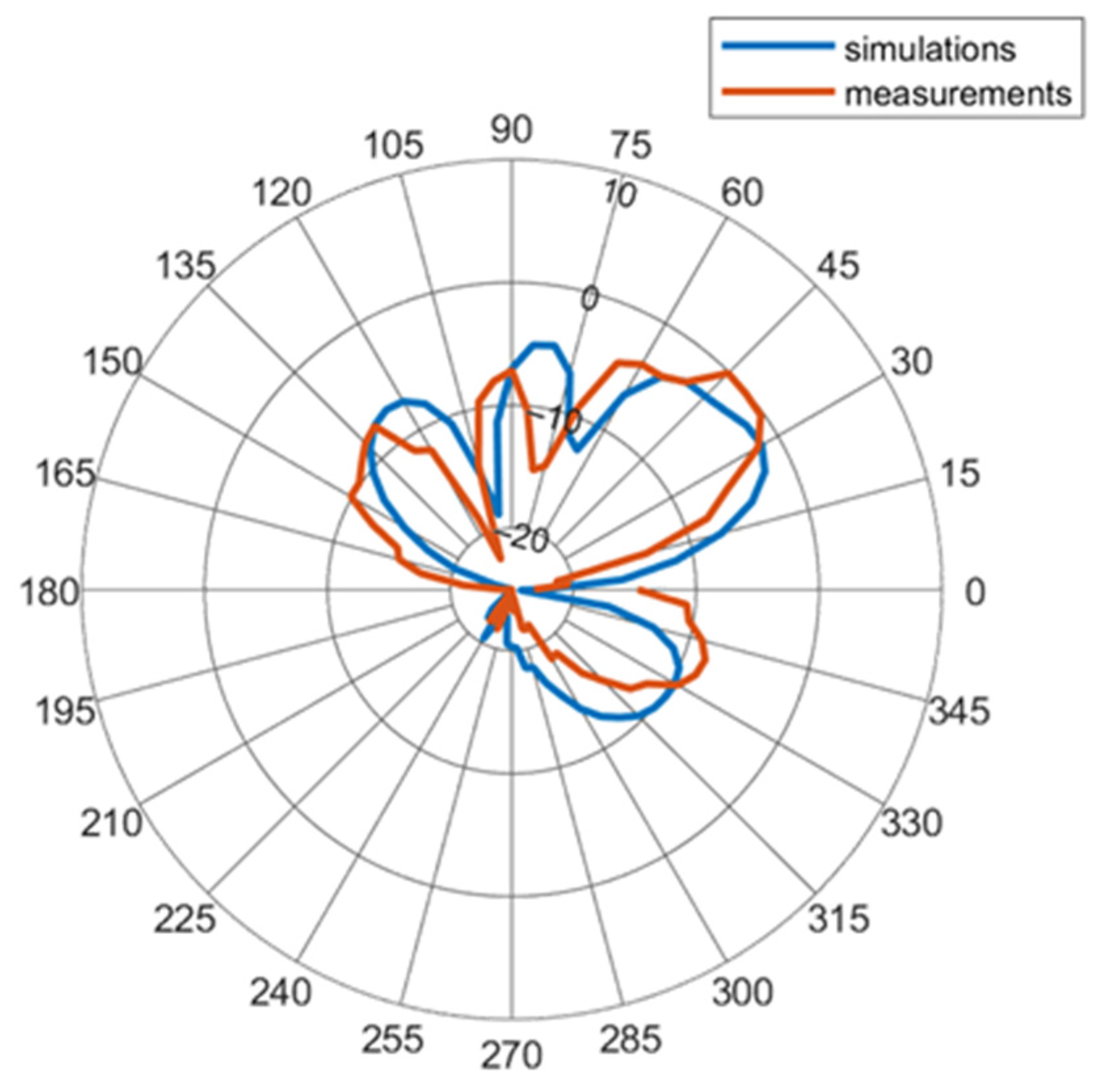
Shifting to a higher frequency of 5.8 GHz, the measured radiation pattern for vertical polarization is depicted in
Figure 21. At this frequency, the maximum gain obtained for vertical polarization from the measurements was 4.7 dBi. Conversely, the radiation pattern for horizontal polarization at 5.8 GHz is also presented in
Figure 22, where the maximum measured gain was recorded as −0.4 dBi.
While the general angular distribution of gain showed remarkable similarity between the simulated and measured results, some minor discrepancies in the overall radiation patterns were observed. These variations can be attributed to inherent differences between the idealized numerical model and the physical phantom used during the experimental measurements. Specifically, subtle variations in anatomical proportions within the phantom, even with comparable overall dimensions to the numerical model, likely contributed to these deviations. Furthermore, the introduction of plastic support structures during the measurement process could have introduced additional scattering or absorption effects not fully accounted for in the purely numerical simulations. Despite these minor variations in the detailed radiation patterns, it is important to emphasize that the maximum gain values obtained from both the simulated and measured results remained comparable, indicating a strong overall agreement between the theoretical predictions and empirical observations.
4. Discussion
The simulation results presented in
Figure 9 demonstrate the antenna’s capability to achieve dual-band operation, effectively covering the designated frequency bands for both 5G (3.4–3.6 GHz) and Wi-Fi (5.725–5.875 GHz, within the broader 5.61–6 GHz and 5.7–6.05 GHz bandwidths) systems. The consistent impedance bandwidth performance when transitioning from free space to on-body placement in the lower band underscores the antenna’s robustness against the detuning effects typically associated with the human body’s proximity at these frequencies. However, minor impedance detuning was observed in the higher band upon on-head placement, which, while present, did not compromise the antenna’s ability to cover the target Wi-Fi band. This observation aligns with previous studies on wearable antennas, which often report a greater sensitivity to the human body’s influence at higher frequencies due to increased dielectric losses and surface wave propagation [
29,
30]. The working hypothesis that the antenna design could maintain sufficient bandwidth for both bands even in the presence of the human head is thus largely supported by the simulation data.
The simulated radiation patterns, as depicted in
Figure 10 and
Figure 11, reveal directional characteristics in the horizontal plane with peak gains of 4.8 dBi and 4.3 dBi at the respective 5G and Wi-Fi bands. These gain values suggest a reasonable level of signal transmission and reception capability for wearable applications. Comparing these simulated gains with those achieved in previous research on wearable antennas for similar frequency bands [
12,
13,
14,
15,
16,
17,
18,
19], this design demonstrates comparable performance, indicating its potential suitability for practical use cases.
The specific absorption rate (SAR) characteristics of the presented antenna design were evaluated, demonstrating its ability to meet human electromagnetic exposure standards. For both designated operating frequencies and at the maximum terminal power levels defined by each standard, the SAR values were found to be below the European Union’s recommended limit of 2.0 W/kg. This compliance is essential for ensuring user safety and satisfying regulatory mandates.
The measured impedance matching results, illustrated in
Figure 18, corroborate the dual-band functionality observed in the simulations. The measured impedance bandwidths (3.40–3.64 GHz and 5.7–6.15 GHz) effectively encompass the target 5G and Wi-Fi bands, exhibiting a slight broadening compared to the simulated results. This discrepancy between the results of measurements and simulations could be attributed to the differences between the numerical model of the head and the physical phantom that was used for the experiments. Another reason for this could be the fabrication tolerances and the inherent complexities of the physical prototype, including the feeding probe compared to the idealized simulation model. However, the differences do not deteriorate the impedance matching below the assumed values.
The measured radiation patterns for linear polarizations (
Figure 19,
Figure 20,
Figure 21 and
Figure 22) show an overall angular distribution of gain that is consistent with the simulated patterns, validating the general radiation characteristics of the antenna. The measured peak gains of 3.6 dBi at 3.5 GHz for horizontal polarization and 4.7 dBi for vertical polarization at 5.8 GHz are slightly lower than their simulated counterparts. These minor discrepancies are likely due to the aforementioned differences between the numerical model and the physical phantom used for measurements. As hypothesized, variations in the anatomical proportions of the phantom, despite similar overall dimensions, and the presence of plastic support structures, which were not accounted for in the simulations, could introduce additional losses and reflections, thereby affecting the measured radiation characteristics. Despite these minor variations, the comparable maximum gain values between the simulation and measurements enable confidence in the antenna’s performance in a real-world scenario.
The findings of this study have several important implications for the development of wearable technology. The successful integration of a dual-band antenna with glasses demonstrates a discreet and potentially comfortable solution for enabling seamless connectivity for both current and emerging wireless communication standards. The consistent performance under on-body conditions, particularly in the lower 5G band, highlights the potential for reliable communication in various usage scenarios. While the higher Wi-Fi band exhibited minor detuning, the maintained bandwidth still allows for robust operation.
Future research directions could focus on further miniaturization of the antenna’s structure to enhance its aesthetic appeal and integration with various eyewear designs. Investigating the impact of different user postures on the antenna’s performance would also be beneficial for real-world deployment. Furthermore, exploring techniques to mitigate the minor impedance detuning observed in the higher band when in close proximity to the head could lead to even more robust performance. This study provides a foundational step towards realizing unobtrusive and efficient wearable antennas for next-generation wireless communication systems.
5. Conclusions
In conclusion, this research successfully developed a novel antenna specifically engineered for seamless integration with conventional eyeglasses, operating efficiently within the 3.5 GHz and 5.8 GHz frequency bands. These bands are critically important for current and emerging 5G and Wi-Fi networks, respectively. A primary design objective was to ensure effortless attachment to existing eyeglass frames without necessitating any structural modifications, thereby opening up compelling new avenues for applications, particularly in assistive technologies for the visually impaired. Both comprehensive simulation and empirical measurement data consistently confirm the antenna’s exceptional impedance matching and demonstrate a commendable maximum gain of 4 dBi across both operational bands. These favorable characteristics position this antenna as a highly viable solution for indoor wireless environments, where effective path loss mitigation is paramount for reliable communication. Furthermore, the antenna’s optimized geometry is inherently compatible with the use of lightweight and flexible materials, such as the one-sided DuPont Pyralux laminate, which is crucial for comfort and wearability in practical applications.
Looking ahead, future research endeavors will concentrate on significantly broadening the antenna’s operating frequency range. This expansion will enable the antenna to accommodate an even wider spectrum of diverse wireless communication systems, enhancing its versatility and applicability across various technological platforms. Additionally, subsequent investigations will explore the integration of this antenna design as a fundamental element within a two-antenna system. This dual-antenna configuration is envisioned as a strategic approach to compensate for the inherent directional radiation patterns typically observed when a single antenna is placed on the human head, thereby improving overall signal coverage and reliability. To achieve this, future work will specifically consider implementing a dual-transmitter architecture in conjunction with frequency diversity techniques. The demonstrably good performance parameters of the currently designed antenna make it an exceptionally promising candidate for these advanced research directions, laying a solid foundation for more robust and adaptable wearable communication systems.


