Article

Development of a Flexible and Conductive Heating Membrane via BSA-Assisted Electroless Plating on Electrospun PVDF-HFP Nanofibers

1
Department of Mechanical Engineering, Chungbuk National University (CBNU), 1 Chungdae-ro, Seowon-gu, Cheongju 28644, Republic of Korea
2
School of Mechanical Engineering, Chungbuk National University (CBNU), 1 Chungdae-ro, Seowon-gu, Cheongju 28644, Republic of Korea
3
Department of Nanoenergy Engineering, Pusan National University, Busandaehak-ro 63 Beon-gil 2, Geumjeong-gu, Busan 46241, Republic of Korea
4
Department of Nano Fusion Technology, Pusan National University, Busandaehak-ro 63 Beon-gil 2, Geumjeong-gu, Busan 46241, Republic of Korea
5
Department of Biomedical Engineering, Daegu Catholic University School of Medicine, 33 Duryugongwon-ro 17-gil, Nam-gu, Daegu 42472, Republic of Korea
*
Authors to whom correspondence should be addressed.
These authors contributed equally to this work.
Appl. Sci. 2025, 15(14), 8023; https://doi.org/10.3390/app15148023
Submission received: 5 June 2025 / Revised: 5 July 2025 / Accepted: 14 July 2025 / Published: 18 July 2025
(This article belongs to the Section Applied Thermal Engineering)

Abstract

Planar heaters are designed to deliver uniform heat across broad surfaces and serve as critical components in applications requiring energy efficiency, safety, and mechanical flexibility, such as wearable electronics and smart textiles. However, conventional metal-based heaters are limited by poor adaptability to curved or complex surfaces, low mechanical compliance, and susceptibility to oxidation-induced degradation. To overcome these challenges, we applied a protein-assisted electroless copper (Cu) plating strategy to electrospun poly(vinylidene fluoride-co-hexafluoropropylene) (PVDF-HFP) nanofiber substrates to fabricate flexible, conductive planar heating membranes. For interfacial functionalization, a protein-based engineering approach using bovine serum albumin (BSA) was employed to facilitate palladium ion coordination and seed formation. The resulting membrane exhibited a dense, continuous Cu coating, low sheet resistance, excellent durability under mechanical deformation, and stable heating performance at low voltages. These results demonstrate that the BSA-assisted strategy can be effectively extended to complex three-dimensional fibrous membranes, supporting its scalability and practical potential for next-generation conformal and wearable planar heaters.

1. Introduction

Planar heaters are engineered to provide uniform heat distribution across wide areas, making them highly suitable for applications demanding energy efficiency and operational stability, such as automotive defogging systems and architectural heating [1,2,3,4]. More recently, their utility has expanded to wearable electronics and flexible devices that function under repeated mechanical deformation and conform to complex geometries [1,5]. However, conventional metal-based heaters typically lack sufficient flexibility, exhibit limited mechanical durability, and are prone to degradation from oxidation, thus limiting their applicability in advanced systems [6,7,8].
Accordingly, selecting substrate materials and fabrication processes that simultaneously provide flexibility, durability, and thermal stability is essential. Poly(vinylidene fluoride-co-hexafluoropropylene) (PVDF-HFP) is a fluorinated copolymer with excellent flexibility, thermal and chemical stability, and high electrical resistivity, making it a promising material to meet these requirements [9,10,11,12]. Furthermore, PVDF-HFP’s dielectric properties minimize interference with the conductive layer and ensure thermal reliability under operation [11]. Owing to these characteristics, PVDF-HFP is highly suitable for use in wearable or conformal thermal devices, especially when fabricated into nanofibrous membranes via electrospinning, where it demonstrates excellent potential as a support material for flexible heater applications. The resulting porous, three-dimensional (3D) architecture enhances mechanical compliance and conformability to curved surfaces while providing a favorable matrix for metal deposition [10,11]. However, due to the inherently high electrical insulation of polymers, achieving thermal functionality requires the formation of a uniform, continuous conductive metal layer throughout the nanofiber network.
Electroplating is a widely used technique that allows for precise control of coating thickness through the application of external current, offering distinct advantages in microfabrication processes. However, this method requires electrically conductive substrates to sustain current flow, and the inherent non-uniformity of current density within the plating bath can result in uneven coatings on complex geometries [13,14,15]. In contrast, electroless plating enables uniform metal deposition without the need for an external power source, making it more suitable for coating insulating and geometrically complex substrates such as electrospun nanofibers. While electroless plating has become a widely adopted strategy for metal functionalization of polymer-based flexible electronics, conventional methods often rely on Pd/Sn catalysts, plasma treatments, or polydopamine adhesion layers. These processes are typically optimized for flat substrates and suffer from limitations such as the need for vacuum systems, toxic reagents, and prolonged processing times [16,17].
To address these limitations, protein-based surface pretreatment strategies have emerged as promising alternatives, with bovine serum albumin (BSA) being one of the most extensively studied examples [17]. BSA contains amine, carboxyl, and thiol groups that enable strong coordination with Pd2+ ions. It also possesses mild reducing capability, allowing for the formation of Pd0 nanoparticles without the use of harsh chemical reductants [18,19,20]. Furthermore, BSA readily adsorbs onto polymer surfaces and introduces hydrophilic moieties that enhance surface wettability, resulting in more uniform metal deposition and improved interfacial adhesion [21]. Owing to its biocompatibility and low toxicity, BSA is particularly well-suited for applications in bioelectronics and biomedical devices [19,22,23,24]. Building upon these advantages, our group previously developed a BSA-assisted electroless copper (Cu) plating method that achieved rapid, uniform metal coating on flat polymer substrates and demonstrated functionality as an effective electrode [20].
In this study, we aim to develop a flexible and conductive planar heater by extending our previously established BSA-assisted electroless Cu plating strategy to electrospun PVDF-HFP nanofibrous membranes. This approach enables uniform metal deposition, strong interfacial adhesion, and stable thermal performance under mechanical deformation, demonstrating its feasibility for low-voltage, flexible heating applications on 3D porous architectures. Incorporation of the BSA pretreatment step significantly reduced sheet resistance and enhanced electrical conductivity, while also improving metal–polymer interfacial adhesion compared to the process without BSA. These enhancements resulted in excellent mechanical durability under repeated deformation. The entire fabrication process was solution-based and free of vacuum or high-energy treatments, enabling facile implementation over large-area or geometrically complex substrates [25,26]. The resulting planar heater maintained stable thermal output even under repeated bending and stretching. These findings confirm the effectiveness of the protein-assisted electroless plating strategy in complex 3D polymer structures and underscore its potential for developing practical, flexible, and conformal thermal devices.

2. Materials and Methods

2.1. Materials

PVDF-HFP (Mw ≈ 455,000), Cu(II) sulfate pentahydrate (CuSO4·5H2O, ≥99.5%, special grade), N,N-dimethylformamide (DMF, ≥99.5%, special grade), SDBS (Mw 348.48, technical grade), BSA (lyophilized powder, ≥96%), ammonium tetrachloropalladate(II) ((NH4)2PdCl4, 99.995%, metals basis), sodium hydroxide (NaOH, ≥98.0%, special grade), and potassium sodium tartrate tetrahydrate (KNaC4H4O6·4H2O, special grade) were obtained from Sigma-Aldrich (St. Louis, MO, USA). Acetone (95 vol%) and a buffer solution (pH 4.00, Grade: S/B) were purchased from Samchun Chemicals (Seoul, Republic of Korea). Formaldehyde solution (36.0–38.0%) was supplied by Wako Pure Chemical Industries, Ltd. (Osaka, Japan). The PDMS (AR) was purchased from Dow Corning (Midland, TX, USA).

2.2. Electrospinning

The electrospinning solution was prepared by dissolving 22 wt% PVDF-HFP in an acetone/DMF mixture (1:4, v/v) and stirring at 600 rpm for 2 h at room temperature (RT). Electrospinning was carried out using a 23-gauge (23G) needle under a 10–12 kV voltage, with a 12 cm tip-to-collector distance, and a feed rate of 0.083 mL/min onto a paper-coated collector. The ambient conditions were maintained at 25–30 °C and 20–30% relative humidity. The resulting electrospun PVDF-HFP nanofiber membrane (ENM) measured 2 cm × 2 cm with a thickness of approximately 400 µm.

2.3. Surface Pretreatment

This procedure was based on our previously reported BSA-assisted Cu plating protocol, with modifications to accommodate the 3D architecture of electrospun nanofibrous substrates [20]. To improve wettability and promote uniform metal deposition, the ENM was immersed in 100 mL of deionized (DI) water containing 5 wt% SDBS and stirred at 90 rpm for 10 min. For seed layer formation, the SDBS-treated ENM was immersed in 100 mL of DI water containing 0.0025 g of BSA and stirred at 90 rpm for 10 min. Catalytic activation was then performed by immersing the BSA/SDBS-treated ENM in a Pd solution, prepared by dissolving 0.05 g of (NH4)2PdCl4 in 100 mL of DI water using a pH 4.00 buffer. The mixture was stirred at 90 rpm for 10 min.

2.4. Electroless Cu Plating

Electroless Cu plating was conducted by immersing the Pd/BSA/SDBS-treated ENM in a plating solution composed of 40 mg/mL NaOH, 140 mg/mL KNaC4H4O6·4H2O, and 30 mg/mL CuSO4·5H2O in DI water. Formaldehyde (0.1 mg/mL) was subsequently added in a 10:1 volume ratio (plating solution/formaldehyde). The reaction proceeded via a Cannizzaro-type mechanism as represented by the following equation [27]:
C u 2 + + 2 H C H O + 4 O H C u + 2 H C O O + 2 H 2 O + 2 H a d s
Plating was performed at RT for 9–13 min. To ensure uniform deposition, the nanofiber web was flipped once during the process. Conductive wires were attached using silver paste. After plating, the samples were rinsed thoroughly with DI water and air-dried in a fume hood for 2 h. The final device, consisting of a Cu layer deposited on the Pd/BSA/SDBS-treated ENM, is referred to as the ENM planar heater (ENMH). A variant fabricated without the BSA step is denoted as ENMH(–BSA step).

2.5. Morphological and Elemental Characterization

Surface and cross-sectional morphologies were examined using an optical microscope (ECLIPSE LV150N; Nikon Corporation, Tokyo, Japan) and a field-emission scanning electron microscope (SEM; ULTRA PLUS; Carl Zeiss AG, Oberkochen, Germany). Samples were cut into ~0.5 cm × 0.5 cm pieces and mounted on SEM stubs using carbon tape. To improve surface conductivity, platinum was sputter-coated onto the samples using an ion sputter coater (G20 Ion Sputter Coater; GSEM Co., Seongnam, Republic of Korea) for 150 s under standard operating conditions. SEM imaging was conducted at an accelerating voltage of 15 kV. Elemental composition was analyzed by energy-dispersive X-ray spectroscopy (EDS; FlatQuard EDS; Bruker Corporation, Billerica, MA, USA) on the same regions imaged by SEM. Elemental mapping was performed at 20 kV with a 3 min acquisition time.
Nanofiber diameter distribution analysis was performed using SEM images from Figure 1a,b, processed with the ImageJ software (version 1.53e). For each sample, diameters of 120 individual nanofibers were measured, and based on these measurements, frequency histograms of the nanofiber diameter distribution as well as the mean and standard deviation values were calculated.

2.6. Contact Angle Measurement

Surface wettability of the specimens was evaluated using a contact angle analyzer (SmartDrop Plus; Femtobiomed Co., Ltd., Seongnam, Republic of Korea). A 5 μL droplet of DI water was dispensed onto the sample surface, and the contact angle was automatically calculated using the instrument’s built-in software.

2.7. Nanoscale Morphology and Crystallinity Analysis

BSA-crosslinked Pd nanoparticles were characterized using a Cs-corrected transmission electron microscope (TEM; JEM-ARM200F NEOARM, JEOL, Tokyo, Japan). Specimens were prepared by reacting BSA with (NH4)2PdCl4 in a pH 4.0 buffer, followed by drop-casting onto carbon-coated Cu grids and drying for 48 h. Imaging was performed at an accelerating voltage of 200 kV with a 0.5 nA probe current and a probe diameter of approximately 0.19 nm. TEM and selected area electron diffraction (SAED) were employed to assess particle morphology, crosslinking behavior, and crystallinity.

2.8. Electrical Property Analysis

Sheet resistance was measured using a four-point probe system (CMT-100MP; AIT Co., Ltd., Suwon, Republic of Korea) on specimens measuring 2 cm × 2 cm with a thickness of approximately 400 µm. After entering the sample dimensions, resistance values were automatically calculated using the instrument’s software.

2.9. Adhesion Strength Test

Adhesion strength between the Cu layer and the ENM was assessed using a 90° T-peel test on a universal testing machine (QM100T; QMESYS Co., Ltd., Bucheon, Republic of Korea) at a peel-off rate of 100 mm/min. Specimens (2 cm × 2 cm, ~400 µm thick) were tested using Scotch™ tape (3M, St. Paul, MN, USA) with a peel area of 20 × 18 mm2. The tape was firmly attached to the ENM surface without air bubbles and allowed to stand for 1 min at 23 °C and 30–40% relative humidity before peeling. The test was repeated five times on each sample while it remained fixed, and a new piece of tape was used for each cycle to ensure consistent adhesion. The same peel rate (100 mm/min) was applied in each cycle to maintain uniform experimental conditions.

2.10. Cu Particle Distribution

To quantify the area fraction of Cu particles transferred to the tape after the peel test, the tape surface was analyzed after performing the test under the same conditions described in Section 2.9. Images of the tape surfaces were captured under consistent lighting conditions using a smartphone camera. The BSA coating was the sole experimental variable; all other processing parameters were kept constant. The Cu plating time was fixed at 11 min. Images were analyzed using ImageJ software (NIH, Bethesda, MD, USA) by adjusting the threshold and performing binary conversion to isolate Cu particle regions. Cu coverage was calculated as the ratio of the segmented Cu particle area to the total image area.
Atomic force microscopy (AFM; Dimension ICON, Bruker, Billerica, MA, USA) was employed to characterize the nanoscale morphology of the peeled tape surfaces. Surface roughness parameters, including the root mean square roughness (Rq) and 10-point height (Rz), were extracted from the AFM images acquired over a 20 × 20 μm2 scan area. These values were used to quantitatively assess the extent of Cu particle transfer and to compare interfacial adhesion properties between samples.

2.11. Thermal Performance Evaluation

The heating performance of the ENMH was evaluated by applying DC voltage using a regulated power supply (2231A-30-3 Triple Channel; Keithley Instruments, LLC., Solon, OH, USA). Surface temperature and distribution were monitored with an infrared thermal camera (PI 640i; Optris GmbH, Berlin, Germany) and analyzed using PIX Connect software (version Rel 3.21.3113.0). Conductive silver paste was applied to both ends of the Cu-coated nanofiber web to enable wire attachment. Temperature measurements were taken from a central rectangular region, excluding the electrode areas, while the sample was maintained within the camera’s focal range. The thermal response was recorded at a frame rate of 32 frames/s.

2.12. Thermal Performance and Environmental Durability Evaluation

The environmental stability of the heater was further assessed by exposing samples to oxidizing conditions (85 °C for 48 h) and humid conditions (85% relative humidity at 25 °C). Heating performance was monitored before and after these exposures to evaluate potential degradation in thermal response.
Washing durability tests were conducted following the ISO 105-C06:2010 standard [28] using a 4 g/L SDBS solution at 40 °C. Samples were stirred in the solution at 800 rpm using a vortex mixer for 30 min. Deionized (DI) water washed samples under the same conditions served as the control group. After washing, the samples were rinsed three times with DI water, subjected to ultrasonic cleaning, and then fully dried at room temperature for 1 h. For selected samples, a PDMS coating was applied prior to washing by drop-casting a diluted PDMS solution (base to curing agent ratio of 10:1, diluted with hexane) onto the surface, followed by thermal curing at 80 °C for 2 h. Surface morphology before and after washing was analyzed by SEM and EDS. Electrical properties were evaluated by measuring sheet resistance (Ω/sq) using a four-point probe method.

2.13. Statistical Analysis

All quantitative experiments were conducted with at least five specimens (n ≥ 5) fabricated under identical processing conditions. Results are presented as mean ± standard deviation (SD). All tests were performed under consistent environmental conditions of room temperature and 30–40% relative humidity. Statistical analysis was conducted using Microsoft Excel 2019 software (Microsoft Corporation, Redmond, WA, USA).

3. Results

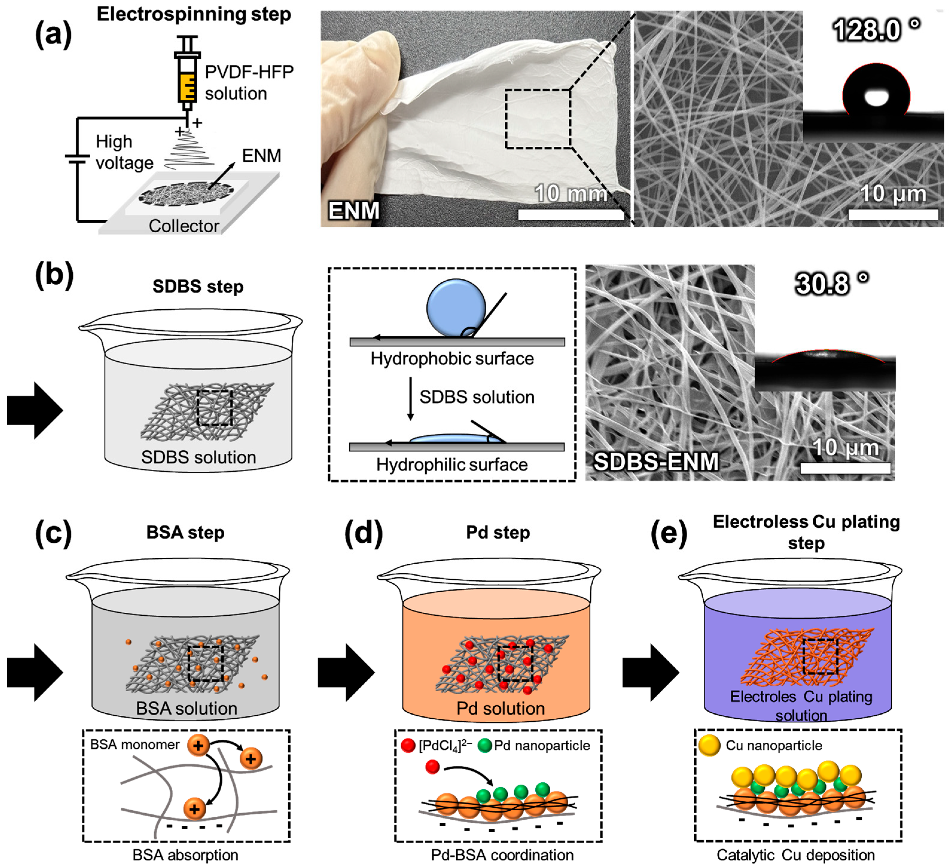
3.1. Fabrication of the ENMH

To ensure consistent fiber morphology, the electrospinning parameters were systematically optimized prior to device fabrication [29]. Specifically, PVDF-HFP solutions with concentrations of 18, 20, 22, and 24 wt% were evaluated (Figure S1a). At lower concentrations (18–20 wt%), insufficient chain entanglement due to low solution viscosity led to Rayleigh instability and frequent bead formation on the fiber surface [30,31]. At 24 wt%, the solution exhibited excessive viscosity, resulting in nozzle clogging and poor jet elongation, ultimately yielding thick and nonuniform fibers [32]. In contrast, the 22 wt% solution provided an optimal balance of viscosity and entanglement, enabling the formation of uniform, bead-free nanofibers with stable morphology.
Further optimization was conducted by varying the applied voltage from 10 to 16 kV using the 22 wt% solution (Figure S1b). Stable jets and straight fibers were obtained at 10–12 kV, while voltages above 14 kV caused excessive whipping and coiling due to high charge density [33]. Such coiled morphologies led to increased fiber overlap and reduced conductivity, making them unsuitable for heating applications. At voltages exceeding 16 kV, the imbalance between electrostatic forces and surface tension induced the formation of irregular blobs and significantly increased fiber diameter variability. Based on these findings, an applied voltage of 10–12 kV and a polymer concentration of 22 wt% were selected as the optimal electrospinning conditions for producing uniform nanofibers with high structural integrity.
The fabrication process of the ENMH is schematically illustrated in Figure 1. A nanofiber membrane was first prepared via electrospinning of a PVDF-HFP solution under a high-voltage electric field, producing a flexible, nonwoven web composed of uniform, interconnected fibers. The electrospun PVDF-HFP nanofibers exhibited an average diameter of 349.1 ± 101.1 nm, with most fibers falling within the 250–500 nm range and a peak frequency observed in the 300–400 nm interval. This result is consistent with the commonly reported diameter range for PVDF-HFP-based nanofibers in the literature (approximately 300–700 nm) [34,35]. For example, Lin et al. reported an average fiber diameter of approximately 500 nm when electrospinning a 17 wt% PVDF-HFP solution under conditions of 15 kV and 0.3 mL/h [36], which is comparable to the fiber dimensions obtained in this study. Such fiber diameters are considered optimal for maintaining structural integrity while providing a high surface area during subsequent metallization processes. The ENM exhibited a hydrophobic surface with a static contact angle of 128.0°, indicating poor wettability (Figure 1a). To improve wettability and enable subsequent solution-based modifications, the ENM was treated with a 5 wt% SDBS solution, which rendered the surface hydrophilic and reduced the contact angle to 30.8° (Figure 1b). Following this treatment, the adsorption of the anionic surfactant SDBS onto the PVDF-HFP fiber surface induced a swelling effect, resulting in an increase in the average fiber diameter to 498.5 ± 150.9 nm—a 42.8% increase compared to the untreated fibers (Figure S2).
Following this, the SDBS-treated ENM was immersed in a BSA solution, resulting in the formation of a protein-based interfacial layer (Figure 1c). The BSA/SDBS-ENM was then treated with a Pd solution, allowing Pd2+ ions to bind electrostatically to the functional groups of the BSA layer (Figure 1d). Electroless Cu plating was subsequently performed on the Pd/BSA/SDBS-ENM (Figure 1e). In the presence of formaldehyde as a reducing agent, Cu2+ ions were spontaneously reduced at the Pd catalytic sites, forming a conformal and continuous Cu layer across the nanofiber web. Finally, conductive silver paste was applied to both ends of the Cu/Pd/BSA/SDBS-ENM to attach wires, completing the ENMH device configuration.

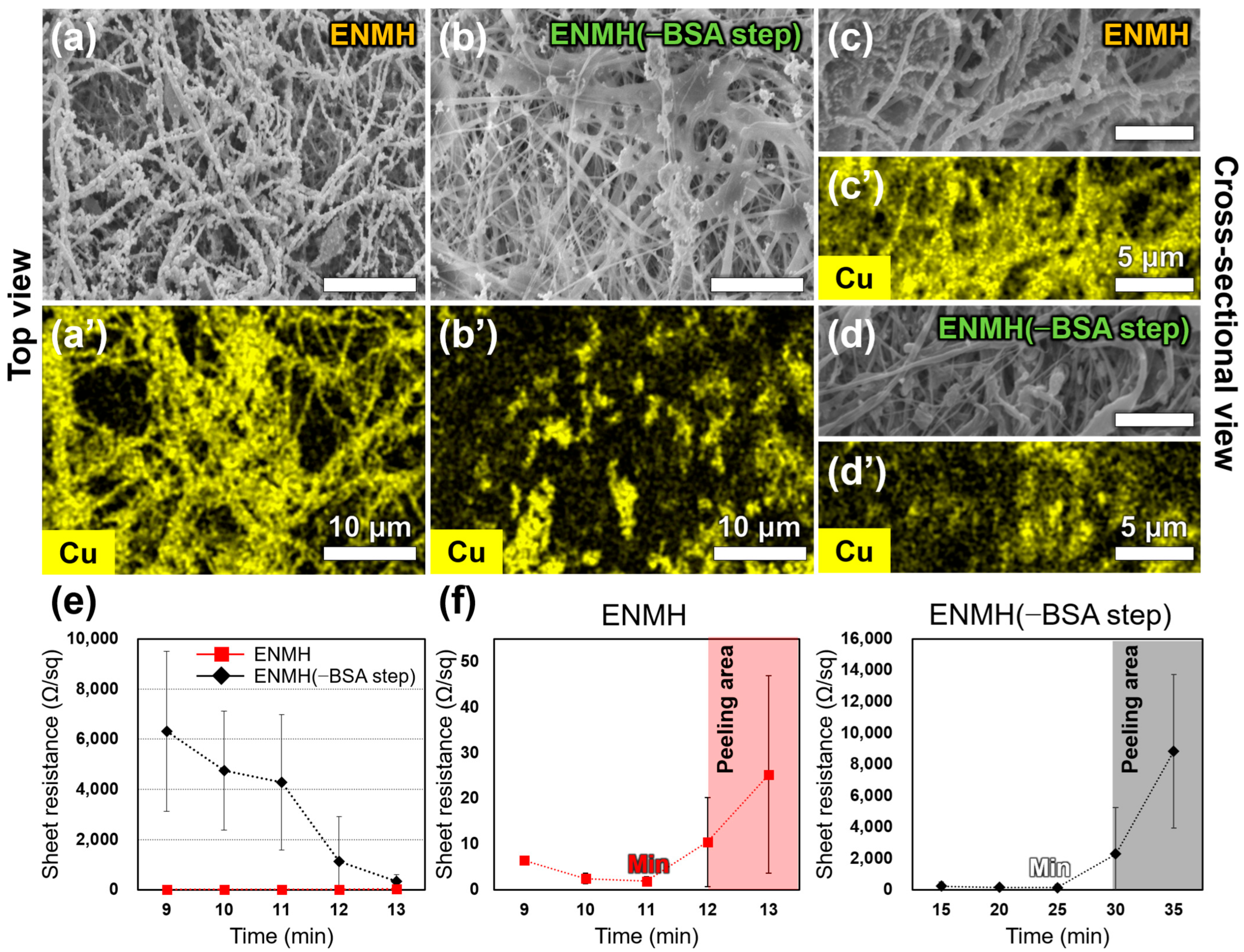
3.2. Effect of the BSA Step on the Morphology and Conductivity of ENMHs

To evaluate the impact of the BSA step on Cu deposition, surface and cross-sectional SEM/EDS analyses were conducted for both ENMH and ENMH(–BSA step) specimens. In the top-view SEM images, the ENMH exhibited a densely packed and uniformly distributed Cu layer on the nanofiber surface (Figure 2a,a’). In contrast, the ENMH(–BSA step) displayed sparse and discontinuous Cu deposition, indicating incomplete surface metallization (Figure 2b,b’).
Cross-sectional analysis focused on the central region of the heater to assess the depth and uniformity of Cu penetration. In the ENMH, strong and continuous Cu signals were observed throughout the cross-section, confirming that the plating layer penetrated deeply and grew uniformly within the nanofiber matrix (Figure 2c,c’). Conversely, the ENMH(–BSA step) showed weak and uneven Cu signals in the same region, suggesting limited infiltration of the Cu layer (Figure 2d,d’).
Electrical properties were compared by measuring sheet resistance over a plating time range of 9–13 min (Figure 2e). The ENMH consistently exhibited low sheet resistance across this range, with a minimum value of 1.895 ± 0.931 Ω/sq at 11 min. In contrast, the ENMH(–BSA step) showed significantly higher resistance throughout the same period. Its lowest value, 328.809 ± 268.666 Ω/sq at 13 min, was approximately 13 times greater than that of the ENMH at the corresponding time point (25.255 ± 21.680 Ω/sq). Moreover, the ENMH(–BSA step) displayed large standard deviations across time points, indicating poor reproducibility.
To assess the onset of electrical instability due to delamination or overgrowth of the Cu layer, sheet resistance was further monitored over an extended plating duration (Figure 2f). The ENMH showed its lowest resistance at 11 min (1.895 ± 0.931 Ω/sq), followed by a sharp increase, indicating possible delamination or structural irregularities from 12 min onward. This was accompanied by increased standard deviation, reflecting decreased uniformity in conductivity. In contrast, the ENMH(–BSA step) reached its minimum resistance at 25 min (127.390 ± 203.106 Ω/sq), approximately 67 times higher than the global minimum of the ENMH. After 30 min, both resistance and standard deviation rose sharply, indicating Cu layer degradation and severe structural instability.

3.3. Effect of BSA Step on Interfacial Adhesion Between the ENM and Cu Layer

The interfacial adhesion between the ENM and the Cu layer was evaluated using a 90° peel test (Figure 3a). In the peel strength–displacement curves, the ENMH exhibited a sharp increase in peel strength after approximately 10 mm, maintaining a steady peel strength in the range of 0.073–0.096 N/mm up to around 30 mm (Figure 3b). In contrast, the ENMH(–BSA step) displayed a lower maximum peel strength of 0.053–0.076 N/mm over the same displacement range, with a relatively stable curve. Although the ENMH maintained a higher peel strength overall, the curve showed more frequent minor fluctuations across the displacement range. In addition, the larger area under the curve for the ENMH indicates that greater peel strength was sustained during the peeling process, reflecting stronger interfacial adhesion.
Transmission electron microscopy (TEM) analysis provided insight into the morphology of Pd nanoparticles. Low-magnification images revealed small, irregularly shaped spherical Pd nanoparticles, several tens of nanometers in diameter, appearing as high-contrast dark spots embedded within a relatively large, low-contrast BSA matrix (Figure 3c). The Pd nanoparticles were uniformly dispersed throughout the BSA layer.
High-resolution TEM images showed clear lattice fringes with an interplanar spacing of approximately 2.25 Å, corresponding to the (111) planes of Pd [37] (Figure 3d). Selected area electron diffraction (SAED) patterns exhibited ring-shaped diffraction features, indicative of a polycrystalline structure [38]. Elemental mapping by energy-dispersive X-ray spectroscopy (EDS) confirmed the presence of C, N, O, S, and Pd elements (Figure 3e). The Pd signal was uniformly distributed, while the C, N, O, and S signals were consistent with the elemental composition of BSA [39].
Scanning electron microscopy (SEM) images of the peeled tape surfaces further supported the adhesion results. The ENMH showed minimal residual Cu particles on the tape, with Cu signals confined to a few localized regions in the corresponding elemental map (Figure 3f). In contrast, the ENMH(–BSA step) displayed a broader distribution of residual Cu particles across the tape surface, with widespread Cu signal coverage. Photographic images of the peeled tape surfaces (Figure S3) provided visual confirmation of this disparity.
To assess interfacial durability, up to five peel cycles were performed, and the Cu coverage on the tape surface was quantitatively analyzed after each cycle using a fresh piece of tape (Figure 3g). As the number of cycles increased, both ENMH and ENMH(–BSA step) showed gradual increases in Cu residue. This trend is attributed to the progressive degradation of interfacial bonding caused by the accumulation of micro-damage and stress during repeated peeling. In particular, the ENMH(–BSA step), which lacks the interfacial reinforcement provided by the BSA layer, exhibited a more rapid deterioration, resulting in a Cu coverage of 64.6% after the fifth cycle—more than 2.5 times higher than that of the ENMH (25.9%). Throughout all cycles, the ENMH consistently maintained a lower level of Cu transfer, indicating superior interfacial stability. In addition to differences in average values, the ENMH(–BSA step) group exhibited large standard deviations even at the first cycle, indicating non-uniform delamination behavior. In contrast, the ENMH group showed a sharp increase in both residue fraction and variability from the third cycle onward, suggesting stress-induced interfacial degradation.
Changes in sheet resistance following repeated peel cycles were also evaluated (Figure 3h). For the ENMH, sheet resistance increased gradually from 2.542 ± 0.135 Ω/sq (Bare) to 3.712 ± 0.125, 4.025 ± 1.491, 7.859 ± 1.379, 8.248 ± 2.004, and 9.982 ± 3.521 Ω/sq after one to five peel cycles, respectively. This represents a 2.7-fold increase between the first and fifth cycles, while maintaining relatively stable electrical conductivity under repeated mechanical stress. In contrast, the ENMH(–BSA step) exhibited a sharp increase in sheet resistance, from 124.300 ± 71.240 Ω/sq (Bare) to 175.890 ± 89.632, 345.880 ± 463.550, 871.235 ± 598.637, 2963.520 ± 1752.960, and 4781.520 ± 2352.100 Ω/sq over the same five cycles (Figure S4). This corresponds to a 27.2-fold increase from the first to the fifth cycle. Notably, the sheet resistance of the ENMH(–BSA step) after the fifth cycle was approximately 479 times higher than that of the ENMH, highlighting the critical role of the BSA layer in enhancing interfacial durability and electrical stability.

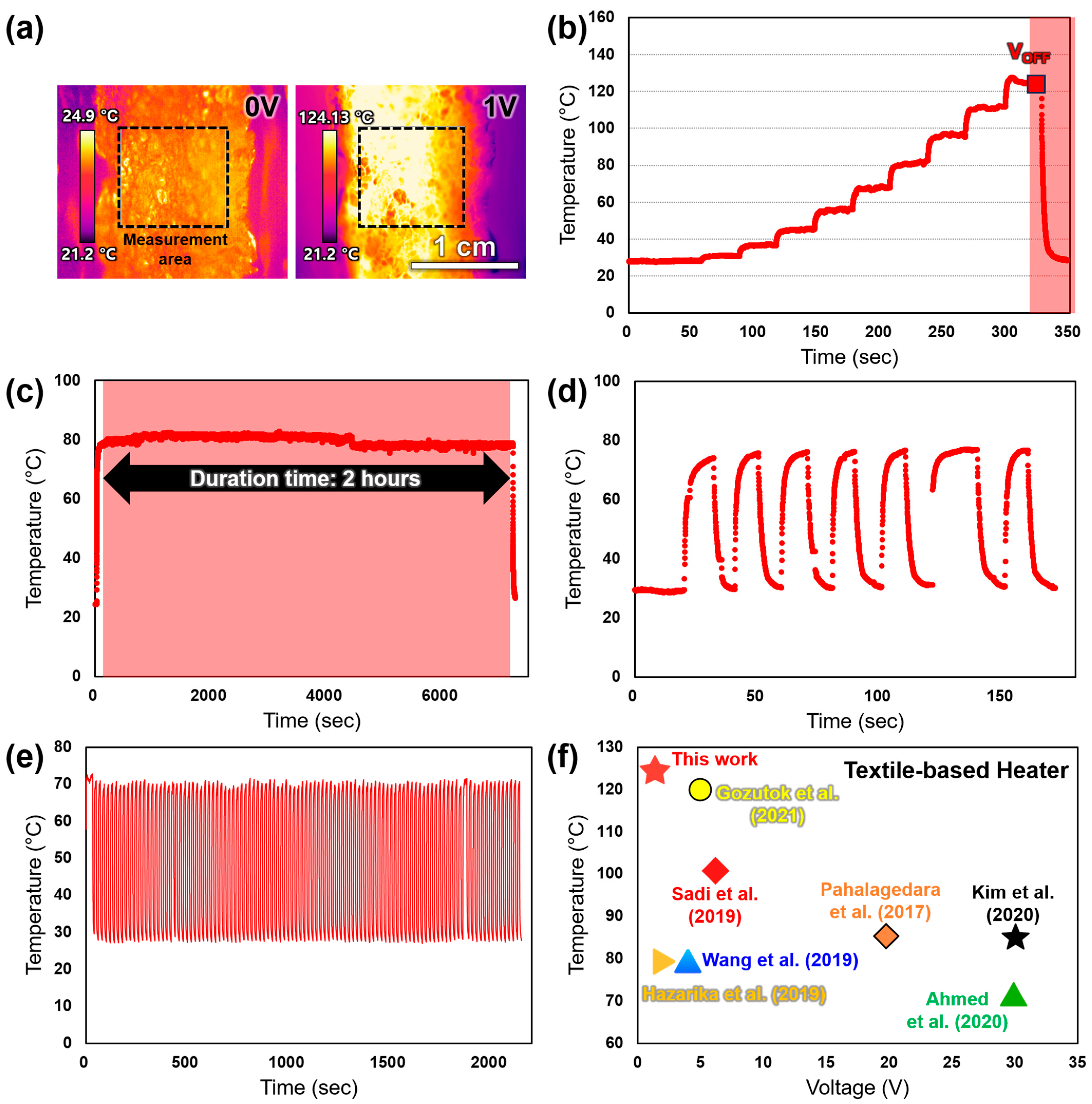
3.4. Thermal Performance Evaluation of the ENMH

The surface temperature of the ENMH before and after voltage application was measured using infrared thermal imaging (Figure 4a). At 0 V, the surface displayed a uniform temperature distribution ranging from 21.2 °C to 24.9 °C, with no observable heating. Upon application of 1 V, the central region exhibited a rapid temperature rise, while the overall surface maintained a uniform thermal profile. The maximum temperature reached 124.1 °C. These results indicate that the ENMH enables effective localized heating under low driving voltage while preserving uniform thermal distribution.
The heating performance of the ENMH was further assessed by incrementally applying voltage from 0.0 V to 1.0 V in 0.1 V steps (Figure 4b). Each voltage was held for 30 s, and the surface temperature was recorded in real time at the central measurement region. The temperature increased in a stepwise manner, with each voltage increment producing a stable and gradual rise. The temperature profile closely followed the programmed voltage input. Average surface temperatures at 0.2 V, 0.4 V, 0.6 V, 0.8 V, and 1.0 V were 28.4 °C, 44.7 °C, 68.4 °C, 96.2 °C, and 124.0 °C, respectively, corresponding to an average increase of approximately 13.3 °C per step. After removing the 1.0 V input, the temperature rapidly returned to baseline. In contrast, the ENMH(–BSA step) exhibited markedly lower thermal performance under identical conditions. Although a similar stair-like increase was observed, the maximum temperature achieved was only about 73.0 °C at 1.0 V (Figure S5).
To evaluate the long-term thermal stability of the ENMH, the surface temperature response was monitored under continuous operation at a constant applied voltage of 0.6 V for 2 h (Figure 4c). Upon voltage application, the ENMH rapidly reached approximately 79 °C, and maintained a stable average temperature of around 80.9 °C throughout the 2 h period. The temperature fluctuation remained within ±1–2 °C over the entire duration, and the temperature drift rate was as low as −1.8 °C/h. No signs of thermal degradation, delamination, or overshooting were observed during the test. After the power was turned off, the temperature quickly returned to its initial value.
Thermal repeatability and response characteristics were assessed using repeated ON/OFF voltage cycles at 10 s intervals under a constant 0.6 V input (Figure 4d). In each cycle, the surface temperature increased rapidly from approximately 29 °C to a peak of 77.1 °C upon voltage application and returned to baseline upon voltage removal. The heating-up time—defined as the time required for the temperature to rise from 10% to 90% of the total increase—was approximately 4.7 s. The cooling-down time—corresponding to the drop from 90% to 10%—was about 3.4 s. These results confirm that the ENMH exhibits excellent thermal responsiveness and reproducibility, with consistent heating and cooling behavior across all cycles. In contrast, the ENMH(–BSA step) sample was tested at the same applied voltage of 0.6 V with repeated ON/OFF cycles at 10 s intervals (Figure S5). Upon voltage application, the surface temperature increased from approximately 26.5 °C to 35.5 °C and returned to the baseline after the power was turned off. The heating and cooling times were calculated to be about 7.8 s and 6.4 s, respectively. Although the maximum temperature was lower, the thermal response was slower than that of the ENMH sample, indicating a reduced heating efficiency.
To evaluate the long-term operational safety of the heater, over 100 ON/OFF voltage cycling tests were performed (Figure 4e). The heater demonstrated stable and repeatable thermal responses throughout the cycling period, exhibiting excellent durability and reliability with no significant degradation in heating rate or responsiveness. Compared to textile-based heaters, the present device achieved a high temperature of 120 °C at a low driving voltage of 0.6 V, outperforming other devices requiring higher voltages, thereby confirming its superior heating efficiency and low-power operation (Figure 4f and Table S1). Furthermore, the heater maintained stable heating performance under oxidative (85 °C for 48 h) and humid (85% relative humidity at 25 °C) conditions, with no notable changes in heating rate, peak temperature, or electrical resistance during ON/OFF cycling at 0.6 V (Figure S6).
To simulate actual washing conditions, the samples were immersed in a 4 g/L SDBS solution at 40 °C under stirring at 800 rpm for 30 min. While samples washed with DI water maintained stable performance without significant changes, those subjected to SDBS washing showed Cu layer dissolution, leading to severe degradation of electrical properties. Surface damage and a decrease in Cu distribution were also observed. In contrast, samples coated with PDMS prior to washing retained their electrical and structural stability under the same conditions, demonstrating that a polymer protective layer can effectively enhance the durability of the heater in washing environments (Figure S7).

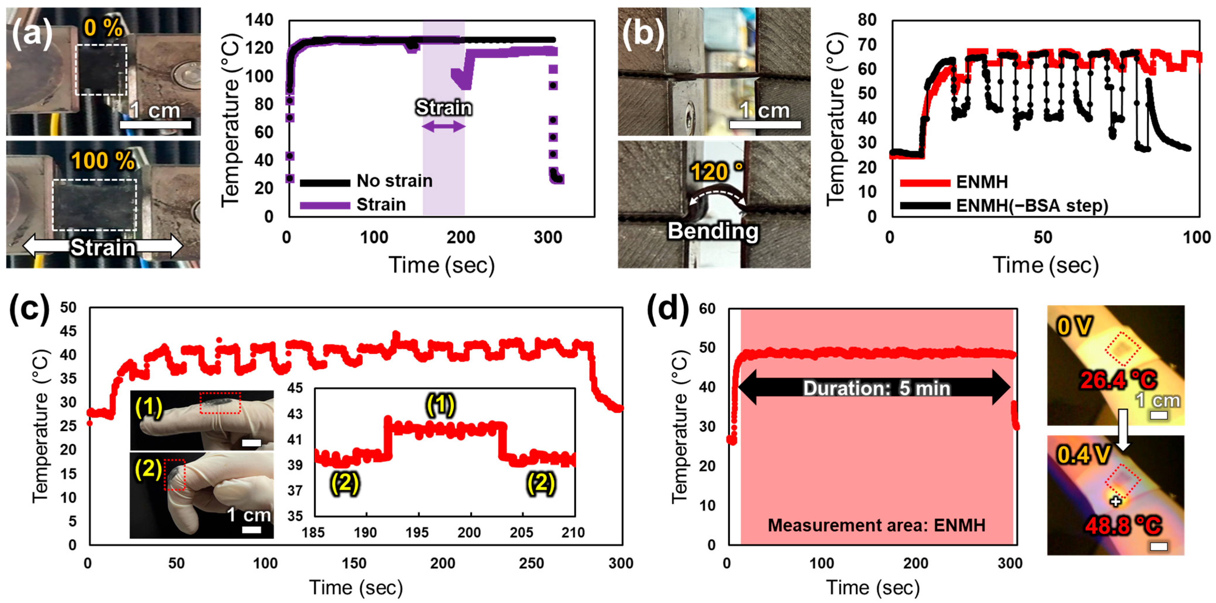
3.5. Evaluation of Mechanical Deformability and Practical Applicability of the ENMH

The heating performance of the ENMH under mechanical stretching was evaluated by applying tensile strain from 0% to 100%, while monitoring surface temperature (Figure 5a). Under a constant voltage of 1 V, the ENMH withstood 100% elongation without physical damage. In the unstretched state, the surface temperature rapidly increased and stabilized at approximately 125 °C. Upon stretching, the temperature temporarily decreased to 93.6 °C but recovered to 94.07% of the initial value, maintaining a stable level of around 118 °C during deformation. After strain release, the temperature remained near the recovered value rather than returning to the initial maximum, indicating sustained thermal output. These results demonstrate that the ENMH retains reliable heating performance under high tensile strain. In contrast, the ENMH(–BSA step) fractured at 100% strain.
The heating performance under repeated bending was assessed by cyclically bending the sample to a 120° angle every 5 s (Figure 5b). Under a constant voltage of 0.6 V, the ENMH maintained stable thermal output throughout the test. The average surface temperature decreased slightly by 6.5%, and no physical damage was observed after eight bending cycles. In contrast, the ENMH(–BSA step) exhibited a gradual temperature decline with each cycle, resulting in a 38.3% reduction in average temperature. Physical failure occurred after the seventh bending cycle, followed by a sharp drop in surface temperature.
Dynamic flexibility on highly mobile areas was evaluated by attaching the ENMH to the knuckle region of a human index finger and measuring thermal response during repeated flexion and extension (Figure 5c). A constant voltage of 0.4 V was applied. When the finger was extended, the surface temperature remained stable at approximately 41.2 °C. During flexion, it decreased to approximately 36.2 °C due to increased electrical resistance from mechanical deformation—a drop of about 5 °C or 12.1%. Despite continuous motion, heating behavior remained consistent. The inset graph (185–215 s) shows repeatable temperature fluctuations corresponding to finger movement cycles.
To assess suitability for wearable clothing integration, the ENMH was mounted on a piece of nonwoven fabric and placed on the inner wrist, a representative curved region of the body (Figure 5d). Under a constant voltage of 0.4 V, the surface temperature rapidly rose and stabilized within the range of 47–49 °C for the 5 min test duration. After the voltage was turned off, the temperature briefly remained elevated before rapidly decreasing. Infrared thermal imaging showed an initial surface temperature of approximately 26.4 °C, increasing to a maximum of 49.8 °C with localized heating. Throughout the 5 min operation, the ENMH maintained stable thermal output without visible physical damage, confirming its practical applicability in wearable systems.

4. Discussion

In this study, a BSA-assisted electroless Cu plating process was applied to a PVDF-HFP nanoweb to develop the ENMH. To enhance interfacial properties, a biomimetic BSA-based interfacial layer was introduced. Experimental results demonstrated that incorporation of the BSA treatment significantly improved the uniformity of the metal coating and the interfacial adhesion to the polymer substrate. These improvements enabled the fabrication of an ENMH with enhanced electrical performance, interfacial stability, and reliable thermal output.
SEM and EDS analyses confirmed that the ENMH featured a dense, continuous Cu coating uniformly distributed throughout the nanofiber network (Figure 2a,a’,c,c’). In contrast, the ENMH(–BSA step) showed non-uniform and discontinuous Cu deposition (Figure 2b,b’,d,d’), indicating that the presence of BSA effectively promoted Pd ion dispersion and immobilization, leading to greater continuity and depth of the electroless Cu layer [20,47]. Further analysis supports the conclusion that BSA also plays a pivotal role in reducing Pd precursors and facilitating the formation of Pd nanoparticles [20] (Figure 3c–e). The uniform Pd distribution suggests that BSA functions as both a mild reducing agent and a stabilizer, preventing nanoparticle aggregation during nucleation and growth [48]. TEM revealed a distinct lattice spacing corresponding to the Pd(111) plane, and the SAED pattern exhibited ring structures, indicating polycrystalline characteristics with high local crystallinity [37]. This structural feature may be advantageous in future electrochemical or catalytic applications. In addition, EDS detection of sulfur supports the involvement of sulfur-containing amino acid residues, such as cysteine in BSA, in coordinating with Pd2+ ions and contributing to their reduction [20]. Taken together, these findings highlight that the BSA-based interfacial layer not only initiates and stabilizes Pd nanoparticle formation but also enhances their colloidal stability. BSA thus functions as an active mediator in guiding Pd nanostructure synthesis rather than merely serving as a passive support [20,47].
The electrical properties of the samples clearly demonstrated the fundamental structural differences induced by BSA pretreatment (Figure 2e). The ENMH group exhibited a low sheet resistance of 1.895 ± 0.931 Ω/sq after 11 min of plating, indicating high conductivity and good process reproducibility. In contrast, the ENMH(–BSA step) group showed a much higher sheet resistance of 328.809 ± 268.666 Ω/sq, along with substantial variation across samples. This pronounced difference can be attributed to the role of BSA in the early stage of plating. BSA promotes more uniform nucleation and Pd2+ ion dispersion, which leads to denser and more homogeneous Cu deposition. The large error bars observed in the BSA-free group do not result from random measurement noise but rather reflect the intrinsic instability in nucleation dynamics and film formation. A smaller standard deviation in sheet resistance across plated samples suggests that BSA pretreatment not only enabled more uniform metal deposition but also ensured consistent outcomes across different samples. Conversely, a larger standard deviation implies that the plating process was unstable, resulting in sample-to-sample variability in coating quality. Therefore, the magnitude of the standard deviation serves as a quantitative indicator of the uniformity and reproducibility of the electroless plating process. The results presented herein quantitatively demonstrate that BSA pretreatment significantly enhances both of these aspects. As plating proceeded under stable conditions, the sheet resistance initially decreased and reached a minimum value as a continuous conductive Cu network was formed (Figure 2f). However, when the plating time exceeded the optimal point, excessive Cu deposition occurred, leading to delamination and subsequent increases in resistance and structural degradation in both groups. In the ENMH group, a sharp rise in both resistance and standard deviation was observed after 12 min, corresponding to the onset of Cu layer delamination. In contrast, the ENMH(–BSA step) group exhibited a similar trend after 30 min, likely due to lower plating efficiency and a delayed transition to a conductive state. These results suggest that excessive plating time can compromise mechanical and electrical stability due to overgrowth of the metal layer, indicating the existence of an optimal plating duration. In particular, the delayed formation of a continuous Cu network in the ENMH(–BSA step) group is attributed to the absence of BSA pretreatment, which results in reduced plating efficiency and prolonged time to achieve conductivity. This finding supports the notion that over-deposition can weaken structural integrity and further demonstrates that BSA pretreatment facilitates rapid and uniform formation of the Cu network in the early plating stage, thereby contributing to lower final resistance.
A similar trend was observed in interfacial adhesion performance. In the 90° T-peel test, the ENMH samples exhibited a relatively high average peel strength in the range of 0.073–0.096 N/mm (Figure 3b), with minimal visible Cu residue on the tape surface after peeling (Figure 3f and Figure S1), indicating strong adhesion between the Cu layer and the nanofiber substrate. In contrast, the ENMH(–BSA step) samples showed lower peel strength and significant Cu residue on the peeled tape, suggesting weaker interfacial bonding. To further quantify adhesion characteristics, the Cu residue was analyzed using the tape area fraction metric, calculated as (residual Cu area/total observed tape area) × 100. This image-based analysis (Figure 3g) provides a numerical indicator of delamination behavior across peeling cycles. After five peel cycles, the tape area fraction for ENMH remained low at 25.9%, whereas the ENMH(–BSA step) reached 64.6%, representing more than a 2.5-fold increase. This result highlights the positive impact of BSA pretreatment on interfacial adhesion stability under repeated mechanical stress. In terms of electrical stability and mechanical durability, the sheet resistance of the ENMH increased from 2.542 ± 0.135 Ω/sq to 9.982 ± 3.521 Ω/sq after five peel cycles, representing an approximate 3.9-fold increase. In contrast, the ENMH(–BSA step) exhibited a dramatic increase from 124.300 ± 71.240 Ω/sq to 4781.520 ± 2352.100 Ω/sq over the same period, corresponding to a 38.5-fold rise (Figure 3h and Figure S4). When comparing the post-peel sheet resistance values directly, the ENMH(–BSA step) was nearly 479 times higher than the ENMH after five cycles, underscoring a critical loss in conductivity and mechanical robustness in the absence of BSA treatment. These results emphasize the essential role of BSA in maintaining interfacial integrity and mitigating fatigue-induced failure under repeated mechanical stress. The differences in Cu residue and electrical degradation between the two groups are further evidenced by the increasing trend in error bar magnitude observed across peel cycles. This reflects not only differences in average interfacial strength but also the variability in delamination behavior within each group. In the ENMH(–BSA step) group, large error bars were already evident after the first peel cycle, indicating poor initial adhesion and highly inconsistent interfacial failure across samples (Figure 3g). The continued increase in variability over subsequent cycles suggests the inherent instability of the metal–polymer interface in the absence of BSA pretreatment. In contrast, the ENMH group maintained low Cu residue and minimal variability for the first two cycles, demonstrating superior mechanical durability and interfacial stability. However, a noticeable increase in error bars was observed from the third cycle onward in both groups, indicating that even with BSA, repeated mechanical stress eventually initiates partial delamination. Nonetheless, the overall level of Cu residue in the ENMH group remained substantially lower than that of the control, reinforcing the conclusion that BSA significantly enhances metal adhesion and resistance to fatigue-induced interfacial failure under cyclic stress. This interpretation is further supported by the changes in electrical properties, which exhibit a consistent trend (Figure 3h and Figure S4). The gradual increase in sheet resistance over successive peel cycles reflects the progressive loss of conductive pathways due to interfacial degradation. Notably, the ENMH samples showed a much smaller increase in resistance and narrower error margins compared to the ENMH(–BSA step) group, indicating that improved interfacial adhesion contributes not only to mechanical robustness but also to enhanced electrical stability.
To ensure stable heating performance and safe operation of the flexible and conductive planar heater (ENMH), two key design strategies were employed. First, a BSA-assisted electroless plating process was used to form a continuous and uniform copper layer over the entire electrospun PVDF-HFP nanofiber network. This uniform metallization promotes even current distribution, enabling consistent and spatially homogeneous Joule heating (Figure 2 and Figure 4a). Second, the 3D fibrous architecture of the PVDF-HFP scaffold enhances in-plane thermal dissipation and prevents localized heat buildup, thereby reducing the risk of hotspot formation. This design was further evaluated in terms of electrical and thermal safety. The ENMH operates at low input voltages, minimizing the risk of electric shock and thermal injury, while maintaining surface temperatures within the safety thresholds established for skin-contact devices under typical operating conditions. In addition, infrared thermal imaging conducted under repeated mechanical deformation and skin attachment (Figure 5c,d) confirmed that the heating behavior remained stable and reproducible, with no evidence of thermal runaway or localized overheating.
The thermal performance of the ENMH represents a key strength of this study, supported by its demonstrated safety and operational stability. The device achieved a surface temperature of 48.8 °C under an applied voltage of only 0.4 V, aligning well with the typical operational range (40–50 °C) required for wearable heating applications (Figure 4a and Figure 5d) [49,50,51]. Given that most commercial wearable heaters are designed to operate at or below this range for safety and comfort, the demonstrated performance at such a low voltage highlights the practical applicability of the ENMH. At a higher input of 1.0 V, the surface temperature increased to 124.1 °C, indicating high thermal efficiency (Figure 4a). The device also exhibited precise temperature responsiveness to stepwise voltage increments of 0.1 V applied every 30 s (Figure 4b), demonstrating controllable and reproducible heating behavior. When a constant voltage of 0.6 V was applied for 5 min, the surface temperature stabilized within a range of 79–80 °C (Figure 4c), further confirming stable thermal output under steady-state conditions. In repeated ON/OFF cycling, the ENMH displayed a heating time of 4.7 s and a cooling time of 3.4 s (Figure 4d), reflecting rapid thermal switching and good reproducibility. The rapid temperature drop upon voltage removal supports the system’s efficient cooling response.
The ENMH demonstrated robust performance under various mechanical deformation conditions. Even under a tensile strain of up to 100%, the device maintained its heating function without structural damage and recovered approximately 94% of its initial surface temperature (Figure 5a). During repeated bending tests, the thermal output remained stable for more than eight cycles (Figure 5b). When attached to a finger joint, the device exhibited only a ~12% fluctuation in surface temperature during flexion, while consistently maintaining overall heating performance (Figure 5c). Notably, when the ENMH was mounted onto a nonwoven textile and applied to a curved body surface such as the wrist, it stably maintained a surface temperature between 47 °C and 49 °C over a 5 min period. Localized heating was clearly visualized using infrared thermal imaging (Figure 5d). These results collectively confirm that the ENMH can maintain structural integrity, stable thermal behavior, and consistent surface temperature under a broad range of mechanical deformation scenarios, including stretching, repeated bending, joint flexion, and conformal attachment to curved surfaces.
Performance degradation was observed under both bending and tensile deformation, indicating the susceptibility of the ENMH system to dynamic mechanical stress (Figure 5c). In the case of repeated finger flexion, a surface temperature drop of approximately 5 °C (12.1%) was recorded, primarily attributed to an increase in electrical resistance induced by mechanical strain. A comparable decline in heating performance was also noted during tensile loading, likely due to strain-induced damage that disrupted the continuity of the conductive layer [52]. This degradation can be explained by three predominant mechanisms. First, localized mechanical stress may cause the formation of microcracks in the copper layer, interrupting continuous current pathways and thereby reducing Joule heating efficiency [52]. Second, interfacial delamination or sliding can occur in regions with insufficient Cu–polymer adhesion, further compromising electrical continuity [53,54]. Third, deformation-induced geometric rearrangement of the nanofiber network, or structural rupture under tensile strain, may increase contact resistance and reduce the effective conductive area, ultimately lowering the overall thermal output [55]. These combined effects offer a plausible explanation for the observed thermal instability under repeated mechanical loading. An effective strategy to mitigate such degradation is the optimization of electrode pattern design. For instance, a horseshoe-shaped pattern can be engineered to accommodate mechanical deformation more flexibly, thereby relieving localized stress and minimizing structural damage. This approach has been reported to enhance both the mechanical durability and thermal stability of flexible heaters under repeated bending or tensile strain [1,56]. Another effective strategy to mitigate such performance degradation involves the incorporation of carbon nanostructures, such as reduced graphene oxide (rGO), into the conductive network. rGO offers high electrical conductivity, excellent mechanical flexibility, and good dispersibility, making it a suitable mechanical backbone in metal–polymer composite systems. When embedded in the conductive layer, such nanostructured networks can help improve stress distribution and suppress crack formation, thereby stabilizing current pathways and reducing thermally induced performance loss during repeated deformation. This approach may offer an effective means of simultaneously enhancing the durability and practical functionality of the ENMH system [57].
Flexible and conductive heaters must satisfy a variety of functional and practical requirements. These include uniform heat distribution, mechanical flexibility, electrical and thermal stability under deformation, a low temperature coefficient of resistance, conformal contact to curved surfaces, and a cost-effective, scalable fabrication process. In addition, structural design tunability and reliable performance under repeated strain are also considered desirable features [1,58,59,60]. The ENMH system developed in this study demonstrates performance characteristics that align well with these criteria. The conformal and continuous copper (Cu) layer penetrates deeply and uniformly into the nanofiber matrix, enabling stable thermal output and uniform heating even on curved surfaces. The use of a BSA-assisted surface modification significantly enhances interfacial adhesion, and the system maintains stable electrical conductivity and thermal responsiveness under repeated stretching and bending, ensuring strong mechanical durability and operational reliability. The fabrication process, based on solution-phase deposition under low-temperature conditions, is structurally simple and scalable, and enables efficient heating at low driving voltages (e.g., 0.4–1.0 V). Moreover, the heater retains stable thermal performance when applied to highly contoured regions such as finger joints and wrists, experimentally confirming its practical applicability as a flexible heater. Considering its structural design adaptability, electro-thermal stability, and overall functional robustness, the ENMH system may also be regarded as a promising thermal material candidate for future applications in smart textiles and next-generation wearable thermotherapy devices.
Currently, the ENMH devices were fabricated in a compact format (2 × 2 cm2) to standardize processing and characterization conditions. However, the solution-based low-temperature plating method and electrospun nanofiber matrix utilized in this study inherently offer structural scalability and processing flexibility, enabling their potential extension to larger-area substrates. These intrinsic features strongly suggest that the ENMH platform can be effectively expanded to various application scenarios requiring coverage of large or geometrically complex surfaces, such as smart textile-based thermal systems, automotive defogging layers, and architectural heating panels [1,2,3,4]. Nevertheless, scaling up the device size may introduce technical challenges, including limited mass transport of the plating solution, geometric distortion, and current density nonuniformity, which can compromise the consistency of Cu deposition and thermal output over extended areas. To overcome these issues, future research will focus on optimizing electrode configurations and precisely controlling plating conditions. Moreover, dynamic heating and thermal stealth functionalities, achievable by modulating input current in response to changing environmental conditions, are also considered promising directions for expanding the capabilities of the ENMH platform. If Joule heating can be precisely controlled through programmable current input, adaptive thermal management may be realized across a wide range of practical applications [61]. Taken together, the flexible and conductive ENMH system offers substantial potential as a foundational technology capable of meeting diverse requirements in next-generation thermal applications.

5. Conclusions

In conclusion, the ENMH system developed in this study exhibits a distinctive combination of performance attributes that address key limitations in current flexible heating technologies. Compared to previously reported platforms, the ENMH enables uniform heat distribution through a conformal and continuous Cu coating, mechanical compliance without the need for structural patterning, and stable operation within the skin-safe temperature range (40–50 °C) under an ultra-low input voltage of 0.4 V. In addition, the device demonstrates excellent electrical and thermal stability under repeated mechanical deformation, without relying on auxiliary functional layers. These advantages are achieved through a solution-processed, pattern-free fabrication route that is inherently scalable and compatible with curved or wearable substrates. Collectively, these results highlight the ENMH’s strong potential as a high-performance thermal platform for practical deployment in next-generation wearable electronics and smart textile applications [1,62].

Supplementary Materials

The following supporting information can be downloaded at: https://www.mdpi.com/article/10.3390/app15148023/s1, Figure S1. Morphological analysis of electrospun fibers under varying conditions. (a) SEM images of electrospun fibers with different polymer concentrations in the spinning solution (18, 20, 22, and 24 wt%). (b) SEM images of electrospun fibers fabricated under different applied voltages during electrospinning (10, 12, 14, and 16 kV). Figure S2. Diameter distribution of electrospun nanofibers. (a) Frequency histogram of nanofiber diameters immediately after electrospinning. (b) Frequency histogram of nanofiber diameters after immersion in SDBS solution. Figure S3. Photographic images of ENMH and ENMH(−BSA step), with surface conditions before and after the peel test. From left to right: Cu-coated nanofiber membrane before the peel test, after the peel test, and adhesive surface of the peeled tape. (b) 3D AFM images of the tape surface after a single peel test for both ENMH and ENMH(−BSA) samples (scan area: 20 × 20 μm2). Figure S4. Variation in sheet resistance of ENMH(−BSA step) over repeated peel test cycles. Figure S5. Thermal performance evaluation of the ENMH(−BSA step). (a) Stepwise voltage increase in 0.1 V increments every 30 s. (b) Short-term cyclic heating behavior under repeated ON/OFF switching of 0.6 V at 10 s intervals. Figure S6. Environmental durability evaluation of the ENMH. (a) Temperature response of the ENMH under oxidative conditions (85 °C for 48 h) during stepwise voltage increments of 0.1 V every 30 s. (b) Temperature response to the same voltage increments after exposure to a humid environment (85% relative humidity at 25 °C). Figure S7. Evaluation of wash durability. (a) Surface SEM and EDS images of the ENMH after washing under different conditions. (b) Comparison of electrical conductivity corresponding to each washing condition. Table S1. Comparison of the heating performance with recently reported textile-based wearable heaters. References [40,41,42,43,44,45,46] are cited in the supplementary materials.

Author Contributions

Conceptualization, G.H.K.; methodology, M.J.C. and D.H.Y.; validation, M.J.C. and D.H.Y.; formal analysis, M.J.C., D.H.Y. and H.N.; investigation, M.J.C. and D.H.Y.; resources, G.H.K.; writing—original draft preparation, H.N.; writing—review and editing, H.N., Y.S.P. and G.H.K.; visualization, M.J.C., D.H.Y. and H.N.; supervision, G.H.K.; project administration, G.H.K.; funding acquisition, H.N. and G.H.K. All authors have read and agreed to the published version of the manuscript.

Funding

This work was supported by the Technology Innovation Program Development Program—Development of alternative gases and process technologies with GWP 150 or less for display deposition and cleaning processes (RS-2023-00266568, Development of alternative gas and process technology below GWP 150 for vapor deposition process for film deposition of display TFT protective film) funded By the Ministry of Trade, Industry & Energy (MOTIE, Korea). This work was supported by the National Research Foundation of Korea (NRF) grant funded by the Korean government (MSIT) (no.RS-2023-00236572).

Institutional Review Board Statement

Not applicable.

Informed Consent Statement

Not applicable.

Data Availability Statement

The original contributions presented in this study are included in the article and Supplementary Materials.

Conflicts of Interest

The authors declare no conflicts of interest.

References

  1. Nemomssa, H.D.; Bossuyt, F.; Vandecasteele, B.; De Pauw, H.; Gidi, N.W.; Bauwens, P. Revolutionizing Patient Care: A Comprehensive Review of Recent Advances in Flexible Printed Heaters for Wearable Medical Applications. Actuators 2025, 14, 1. [Google Scholar] [CrossRef]
  2. Chang, T.-B.; Sheu, J.-J.; Huang, J.-W. High-Efficiency HVAC System with Defog/Dehumidification Function for Electric Vehicles. Energies 2021, 14, 46. [Google Scholar] [CrossRef]
  3. Yang, J.S.; Min, J.K.; Yang, C.; Jung, K. Numerical Studies of Natural Convection Phenomena for a Vertical Cylinder with Multiple Lateral Baffles in Triangular and Hexagonal Enclosures. Case Stud. Therm. Eng. 2023, 45, 102971. [Google Scholar] [CrossRef]
  4. Lee, J.-G.; Lee, J.-H.; An, S.; Kim, D.-Y.; Kim, T.-G.; Al-Deyab, S.S.; Yarin, A.L.; Yoon, S.S. Highly Flexible, Stretchable, Wearable, Patternable and Transparent Heaters on Complex 3D Surfaces Formed from Supersonically Sprayed Silver Nanowires. J. Mater. Chem. A 2017, 5, 6677–6685. [Google Scholar] [CrossRef]
  5. Liu, Q.; Tian, B.; Liang, J.; Wu, W. Recent Advances in Printed Flexible Heaters for Portable and Wearable Thermal Management. Mater. Horiz. 2021, 8, 1634–1656. [Google Scholar] [CrossRef] [PubMed]
  6. Kim, A.-Y.; Kim, M.K.; Hudaya, C.; Park, J.H.; Byun, D.; Lim, J.-C.; Lee, J.K. Oxidation-Resistant Hybrid Metal Oxide/Metal Nanodots/Silver Nanowires for High Performance Flexible Transparent Heaters. Nanoscale 2016, 8, 3307–3313. [Google Scholar] [CrossRef] [PubMed]
  7. Wang, Y.; Yokota, T.; Someya, T. Electrospun Nanofiber-Based Soft Electronics. NPG Asia Mater. 2021, 13, 22. [Google Scholar] [CrossRef]
  8. Shchegolkov, A.V.; Shchegolkov, A.V.; Kaminskii, V.V.; Chumak, M.A. Smart Polymer Composites for Electrical Heating: A Review. J. Compos. Sci. 2024, 8, 522. [Google Scholar] [CrossRef]
  9. Brito-Pereira, R.; Queirós, J.M.; Celaya-Azcoaga, L.; Fernández de Luiz, R.; Martins, P.; Lanceros-Mendez, S. Hexavalent Chromium Dual Water Remediation and Sensing Based on Hybrid Polymer/Metal-Organic Framework Composites. J. Environ. Chem. Eng. 2024, 12, 113839. [Google Scholar] [CrossRef]
  10. Tang, Y.; Xiong, Y.; Wu, L.; Xiong, X.; Me, T.; Wang, X. A Solid-State Lithium Battery with PVDF–HFP-Modified Fireproof Ionogel Polymer Electrolyte. ACS Appl. Energy Mater. 2023, 6, 4016–4026. [Google Scholar] [CrossRef]
  11. Sousa, R.E.; Nunes-Pereira, J.; Ferreira, J.C.C.; Costa, C.M.; Machado, A.V.; Silva, M.M.; Lanceros-Mendez, S. Microstructural Variations of Poly (Vinylidene Fluoride Co-Hexafluoropropylene) and Their Influence on the Thermal, Dielectric and Piezoelectric Properties. Polym. Test. 2014, 40, 245–255. [Google Scholar] [CrossRef]
  12. Yuennan, J.; Muensit, N. Preparation and Characterization of Flexible PVDF-HFP Film for Piezoelectric Applications. IOP Conf. Ser. Mater. Sci. Eng. 2020, 715, 012107. [Google Scholar] [CrossRef]
  13. Feng, Y.; Yao, Y.; Wang, S.; Ma, X.; Han, Y.; Feng, J.; Wen, J.; Tian, R.; Sun, Q.; Tian, Y. Role of Hetero-Doped Reduced Graphene Oxide in Suppressing Elemental Dissolution in Manganese Selenide Cathode for Aqueous Zinc-Ion Batteries. ChemSusChem 2024, 18, e202402101. [Google Scholar] [CrossRef] [PubMed]
  14. Lelevic, A.; Walsh, F.C. Electrodeposition of Ni–P Alloy Coatings: A Review. Surf. Coat. Technol. 2019, 369, 198–220. [Google Scholar] [CrossRef]
  15. Wu, L.-P.; Zhao, J.-J.; Xie, Y.-P.; Yang, Z.-D. Progress of Electroplating and Electroless Plating on Magnesium Alloy. Trans. Nonferrous Met. Soc. China 2010, 20 (Suppl. S2), s630–s637. [Google Scholar] [CrossRef]
  16. Aminu, T.Q.; Juybari, H.F.; Warsinger, D.M.; Bahr, D.F. Electroless Deposition for Robust and Uniform Copper Nanoparticles on Electrospun Polyacrylonitrile (PAN) Microfiltration Membranes. Membranes 2024, 14, 198. [Google Scholar] [CrossRef] [PubMed]
  17. Kim, N.K.; Kang, S.M.; Kim, T.; Kim, S.; Kim, G.H. Electroless Plating on Polymer Surfaces: Comprehensive Review of Mechanism, Process, Analysis, and Future Applications. Adv. Mater. Interfaces, 2025; in press. [Google Scholar] [CrossRef]
  18. Li, F.; Yeh, S.; Shi, Q.; Wang, P.; Wu, H.; Xin, J. A Novel Thermal-Driven Self-Assembly Method to Prepare Albumin Nanoparticles: Formation Kinetics, Degradation Behavior and Formation Mechanism. Int. J. Nanomed. 2022, 23, 250. [Google Scholar] [CrossRef] [PubMed]
  19. Mohseni, N.; Moodi, M.; Kefayat, A.; Shokati, F.; Molaabasi, F. Challenges and Opportunities of Using Fluorescent Metal Nanocluster-Based Colorimetric Assays in Medicine. ACS Omega 2024, 9, 3143–3163. [Google Scholar] [CrossRef] [PubMed]
  20. Kim, G.H.; Hwang, H.Y.; An, T. In Situ BSA (Bovine Serum Albumin) Assisted Electroless Plating Method with Superior Adhesion Property. Adv. Mater. Interfaces 2022, 9, 2101203. [Google Scholar] [CrossRef]
  21. Wangkam, T.; Yodmongkol, S.; Disrattakit, J.; Sutapun, B.; Amarit, R.; Somboonkaew, A.; Srikhirin, T. Adsorption of Bovine Serum Albumin (BSA) on Polystyrene (PS) and Its Acid Copolymer. Curr. Appl. Phys. 2012, 12, 44–52. [Google Scholar] [CrossRef]
  22. Nawade, A.; Busi, K.B.; Dalapati, G.K.; Chakrabortty, S.; Mukhopadhyyay, S. Hybrid Inorganic-Biomolecular Materials for Bioelectronics Applications. J. Electron. Mater. 2025, 54, 3509–3519. [Google Scholar] [CrossRef]
  23. Sivaselvam, S.; Mohankumar, A.; Thiruppathi, G.; Sundararaj, P.; Viswanathan, C.; Ponpandian, N. Engineering the Surface of Graphene Oxide with Bovine Serum Albumin for Improved Biocompatibility in Caenorhabditis elegans. Nanoscale Adv. 2020, 2, 5219. [Google Scholar] [CrossRef] [PubMed]
  24. Fang, P.H.; Chen, G.X.; Wang, S.; Teng, C.H.; Huang, W.C.; Cheng, H.L.; Chou, W.Y. Biocompatible OFETs for Selective and Real-Time Bacterial Detection Using BSA and Lysozyme Layers. ACS Appl. Bio Mater. 2025, 8, 2867–2874. [Google Scholar] [CrossRef] [PubMed]
  25. Sun, L.; Wang, J.; Matsui, H.; Lee, S.; Wang, W.; Guo, S.; Chen, H.; Fang, K.; Ito, Y.; Inoue, D.; et al. All-Solution-Processed Ultraflexible Wearable Sensor Enabled with Universal Trilayer Structure for Organic Optoelectronic Devices. Sci. Adv. 2024, 10, eadk9460. [Google Scholar] [CrossRef] [PubMed]
  26. Sun, L.; Fukuda, K.; Someya, T. Recent Progress in Solution-Processed Flexible Organic Photovoltaics. NPJ Flex. Electron. 2022, 6, 89. [Google Scholar] [CrossRef]
  27. van Meerakker, J.E.A.M.; Scholtens, E. Side Reactions in Electroless Copper Solutions with Formaldehyde as Reducing Agent. Ber. Bunsenges. Phys. Chem. 1989, 93, 786–791. [Google Scholar] [CrossRef]
  28. ISO 105-C06:2010; Textiles—Tests for Colour Fastness—Colour Fastness to Domestic and Commercial Laundering. International Organization for Standardization: Geneva, Switzerland, 2010.
  29. Abdulhussain, R.; Adebisi, A.; Conway, B.R.; Asare-Addo, K. Electrospun nanofibers: Exploring process parameters, polymer selection, and recent applications in pharmaceuticals and drug delivery. J. Drug Deliv. Sci. Technol. 2023, 90, 105156. [Google Scholar] [CrossRef]
  30. Yarin, A.L.; Koombhongse, S.; Reneker, D.H. Bending instability in electrospinning of nanofibers. J. Appl. Phys. 2001, 89, 3018–3026. [Google Scholar] [CrossRef]
  31. Shenoy, S.L.; Bates, W.D.; Frisch, H.L.; Wnek, G.E. Role of chain entanglements on fiber formation during electrospinning of polymer solutions: Good solvent, non-specific polymer–polymer interaction limit. Polymer 2005, 46, 3372–3384. [Google Scholar] [CrossRef]
  32. Zhang, C.; Yuan, X.; Wu, L.; Han, Y.; Sheng, J. Study on morphology of electrospun poly(vinyl alcohol) mats. Eur. Polym. J. 2005, 41, 423–432. [Google Scholar] [CrossRef]
  33. Nugraha, A.S.; Chou, C.C.; Yu, P.H.; Lin, K.L. Effects of applied voltage on the morphology and phases of electrospun poly(vinylidene difluoride) nanofibers. Polym. Int. 2022, 71, 1176–1183. [Google Scholar] [CrossRef]
  34. He, W.; Ding, H.; Chen, X.; Yang, W. Three-dimensional LLZO/PVDF-HFP fiber network-enhanced ultrathin composite solid electrolyte membrane for dendrite-free solid-state lithium metal batteries. J. Membr. Sci. 2023, 665, 121095. [Google Scholar] [CrossRef]
  35. Sha, Z.; Boyer, C.; Li, G.; Yu, Y.; Allioux, F.M.; Kalantar-Zadeh, K.; Wang, C.H.; Zhang, J. Electrospun liquid metal/PVDF-HFP nanofiber membranes with exceptional triboelectric performance. Nano Energy 2022, 92, 106713. [Google Scholar] [CrossRef]
  36. Lin, M.-F.; Chang, K.-W.; Lee, C.-H.; Wu, X.-X.; Huang, Y.-C. Electrospun P3HT/PVDF-HFP semiconductive nanofibers for triboelectric nanogenerators. Sci. Rep. 2022, 12, 14842. [Google Scholar] [CrossRef] [PubMed]
  37. Narkhede, N.; Uttam, B.; Rao, C.P. Calixarene-Assisted Pd Nanoparticles in Organic Transformations: Synthesis, Characterization, and Catalytic Applications in Water for C–C Coupling and for the Reduction of Nitroaromatics and Organic Dyes. ACS Omega 2019, 4, 4908–4917. [Google Scholar] [CrossRef] [PubMed]
  38. Williams, D.B.; Carter, C.B. Transmission Electron Microscopy: A Textbook for Materials Science, 2nd ed.; Springer: New York, NY, USA, 2009. [Google Scholar] [CrossRef]
  39. Coppage, R.; Slocik, J.M.; Briggs, B.D.; Frenkel, A.I.; Naik, R.R.; Knecht, M.R. Determining Peptide Sequence Effects That Control the Size, Structure, and Function of Nanoparticles. ACS Nano 2012, 6, 1625–1636. [Google Scholar] [CrossRef] [PubMed]
  40. Wang, Q.-W.; Zhang, H.-B.; Liu, J.; Zhao, S.; Xie, X.; Liu, L.; Yang, R.; Koratkar, N.; Yu, Z.-Z. Multifunctional and water-resistant MXene-decorated polyester textiles with outstanding electromagnetic interference shielding and Joule heating performances. Adv. Funct. Mater. 2019, 29, 1806819. [Google Scholar] [CrossRef]
  41. Hazarika, A.; Deka, B.K.; Jeong, C.; Park, Y.B.; Park, H.W. Biomechanical Energy-Harvesting Wearable Textile-Based Personal Thermal Management Device Containing Epitaxially Grown Aligned Ag-Tipped-NixCo1−xSe Nanowires/Reduced Graphene Oxide. Adv. Funct. Mater. 2019, 29, 1903114. [Google Scholar] [CrossRef]
  42. Sadi, M.S.; Yang, M.; Luo, L.; Cheng, D.; Cai, G.; Wang, X. Direct screen printing of single-faced conductive cotton fabrics for strain sensing, electrical heating and color changing. Cellulose 2019, 26, 6179–6188. [Google Scholar] [CrossRef]
  43. Pahalagedara, L.R.; Siriwardane, I.W.; Tissera, N.D.; Wijesena, R.N.; de Silva, K.M.N. Carbon black functionalized stretchable conductive fabrics for wearable heating applications. RSC Adv. 2017, 7, 19174–19180. [Google Scholar] [CrossRef]
  44. Gozutok, Z.; Agırbas, O.; Bahtiyari, M.I.; Ozdemir, A.T. Low-voltage textile-based wearable heater systems fabricated by printing reactive silver inks. Sens. Actuators A Phys. 2021, 322, 112610. [Google Scholar] [CrossRef]
  45. Ahmed, A.; Jalil, M.A.; Hossain, M.; Moniruzzaman; Adak, B.; Islam, M.T.; Parvez, S.; Mukhopadhyay, S. A PEDOT:PSS and graphene-clad smart textile-based wearable electronic Joule heater with high thermal stability. J. Mater. Chem. C 2020, 8, 16204–16215. [Google Scholar] [CrossRef]
  46. Kim, H.; Kim, H.S.; Lee, S. Thermal insulation property of graphene/polymer-coated textile based multi-layer fabric heating element with aramid fabric. Sci. Rep. 2020, 10, 17586. [Google Scholar] [CrossRef] [PubMed]
  47. Ahn, T.-C.; Hong, H.-S.; Kim, S.-S.; Hwang, H.-Y. Improvement of Adhesion Characteristics of Copper Electrodes on Polyvinylidene Fluoride Films Using Bovine Serum Albumin. Int. J. Adhes. Adhes. 2022, 112, 103025. [Google Scholar] [CrossRef]
  48. Ha, J.W.; Choi, J.Y.; Boo, Y.C. Differential Effects of Histidine and Histidinamide versus Cysteine and Cysteinamide on Copper Ion-Induced Oxidative Stress and Cytotoxicity in HaCaT Keratinocytes. Antioxidants 2023, 12, 801. [Google Scholar] [CrossRef] [PubMed]
  49. Lee, S.; Jang, D.; Chung, Y.S.; Lee, S. Cost-Effective and Highly Efficient Surface Heating Elements Using High Thermal Conductive Carbon Fibers. Compos. Part A Appl. Sci. Manuf. 2020, 137, 105992. [Google Scholar] [CrossRef]
  50. Claypole, A.; Claypole, J.; Leeder, J.; Stevens, G.; Johnson, F.; Bezodis, N.; Parker, M.; Claypole, T.; Gethin, D.; Kilduff, L. Large Area, Stretchable, Wearable, Screen-Printed Carbon Heaters for Use in Elite Sport. J. Coat. Technol. Res. 2023, 20, 261–273. [Google Scholar] [CrossRef]
  51. NASA Office of the Chief Health & Medical Officer. Physiological Effects of Touch Temperature (OCHMO-TB-009 Rev A). Available online: https://www.nasa.gov/wp-content/uploads/2023/12/ochmo-tb-009-touch-temperature.pdf (accessed on 5 June 2025).
  52. Lee, S.-Y.; Park, K.R.; Kang, S.-G.; Lee, J.-H.; Jeon, E.-C.; Shim, C.-H.; Ahn, J.-P.; Kim, D.-I.; Han, H.N.; Joo, Y.-C.; et al. Selective Crack Suppression during Deformation in Metal Films on Polymer Substrates Using Electron Beam Irradiation. Nat. Commun. 2019, 10, 4454. [Google Scholar] [CrossRef] [PubMed]
  53. Zhou, Y.; Lian, H.; Li, Z.; Yin, L.; Ji, Q.; Li, K.; Qi, F.; Huang, Y. Crack Engineering Boosts the Performance of Flexible Sensors. VIEW 2022, 3, 20220025. [Google Scholar] [CrossRef]
  54. Mei, H.; Pang, Y.; Im, S.H.; Huang, R. Fracture, Delamination, and Buckling of Elastic Thin Films on Compliant Substrates. In Proceedings of the Intersociety Conference on Thermal and Thermomechanical Phenomena in Electronic Systems (ITherm), Orlando, FL, USA, 28–31 May 2008; IEEE: Piscataway, NJ, USA, 2008; pp. 762–767. [Google Scholar] [CrossRef]
  55. Jang, D.-W.; Lee, J.-H.; Kim, A.; Lee, S.-B.; Hong, S.-G. Self-heating-induced deterioration of electromechanical performance in polymer-supported metal films for flexible electronics. Sci. Rep. 2017, 7, 12506. [Google Scholar] [CrossRef] [PubMed]
  56. Jahanshahi, A.; Gonzalez, M.; van den Brand, J.; Bossuyt, F.; Vervust, T.; Verplancke, R.; Vanfleteren, J.; De Baets, J. Stretchable Circuits with Horseshoe Shaped Conductors Embedded in Elastic Polymers. Jpn. J. Appl. Phys. 2013, 52, 05DA18. [Google Scholar] [CrossRef]
  57. Wang, S.; Zeng, G.; Sun, Q.; Feng, Y.; Wang, X.; Ma, X.; Li, J.; Zhang, H.; Wen, J.; Feng, J.; et al. Flexible Electronic Systems via Electrohydrodynamic Jet Printing: A MnSe@rGO Cathode for Aqueous Zinc-Ion Batteries. ACS Nano 2023, 17, 13256–13268. [Google Scholar] [CrossRef] [PubMed]
  58. Veeramuthu, L.; Chen, B.-Y.; Tsai, C.-Y.; Liang, F.-C.; Venkatesan, M.; Jiang, D.-H.; Chen, C.-W.; Cai, X.; Kuo, C.-C. Novel stretchable thermochromic transparent heaters designed for smart window defroster applications by spray coating silver nanowire. RSC Adv. 2019, 9, 35786–35796. [Google Scholar] [CrossRef] [PubMed]
  59. Chen, J.; Shi, Y.; Ying, B.; Hu, Y.; Gao, Y.; Luo, S.; Liu, X. Kirigami-enabled stretchable laser-induced graphene heaters for wearable thermotherapy. Mater. Horiz. 2024, 11, 2010–2020. [Google Scholar] [CrossRef] [PubMed]
  60. Ahn, J.-Y.; Lee, D.-K.; Kim, M.-G.; Kim, W.-J.; Park, S.-H. Temperature-Responsive Hybrid Composite with Zero Temperature Coefficient of Resistance for Wearable Thermotherapy Pads. Micromachines 2025, 16, 108. [Google Scholar] [CrossRef] [PubMed]
  61. Salihoglu, O.; Uzlu, H.B.; Yakar, O.; Aas, S.; Balci, O.; Kakenov, N.; Balci, S.; Olcum, S.; Süzer, S.; Kocabas, C. Graphene-Based Adaptive Thermal Camouflage. Nano Lett. 2018, 18, 4541–4548. [Google Scholar] [CrossRef] [PubMed]
  62. Fang, S.; Wang, R.; Ni, H.; Liu, H.; Liu, L. A Review of Flexible Electric Heating Element and Electric Heating Garments. J. Ind. Text. 2020, 51, 101S–136S. [Google Scholar] [CrossRef]
Figure 1. The fabrication process of the ENMH. (a) Collection of PVDF-HFP nanofiber webs via electrospinning, with real image, SEM image, and water contact angle measurement of the ENM after immediately electrospinning. (b) Surface modification of ENM through immersion in an SDBS solution, with SEM image and water contact angle of the SDBS-ENM. (c) Formation of a BSA seed layer on the SDBS-ENM. (d) Treatment of the BSA/SDBS-ENM with a Pd activation solution for catalytic activation. (e) Electroless Cu plating process performed on the Pd-activated BSA/SDBS-ENM.
Applsci 15 08023 g001
Figure 2. Morphological and electrical characteristics of Cu-deposited PVDF nanofiber webs. (a,b) Surface SEM images of ENMH and ENMH(−BSA step), respectively. (a’,b’) EDS mapping images corresponding to (a,b). (c,d) Cross-sectional SEM images of ENMH and ENMH(−BSA step), respectively. (c’,d’) EDS mapping images of the cross-sections shown in (c,d). (e) Comparison of electrical conductivity between ENMH and ENMH(−BSA step) as a function of electroless plating time. (f) Sheet resistance of (Left) ENMH and (Right) ENMH(−BSA step) as a function of electroless plating time. Error bars represent standard deviation (n ≥ 5).
Applsci 15 08023 g002
Figure 3. Adhesion analysis between the ENM and the deposited Cu layer. (a) Schematic illustration of the 90°peel test. (b) Peel strength comparison for ENMH and ENMH(−BSA step). TEM characterizations of Pd nanoparticles crosslinked by BSA on ENMH: (c) TEM image illustrating the overall morphology and particle dispersion. (d) High-resolution TEM image and corresponding SAED pattern of a representative particle. (e) TEM elemental mapping images of C, N, O, S, and Pd. (f) SEM and EDS mapping images of the peeled tape adhesive surface for (Left) ENMH and (Right) ENMH(−BSA step) showing the distribution of residual Cu. (g) Surface coverage of Cu particles on the tape as a function of the number of peel cycles. (h) Sheet resistance of crosslinked samples after repeated peel tests. Error bars represent standard deviation (n ≥ 5).
Applsci 15 08023 g003
Figure 4. Thermal performance evaluation of the ENMH. (a) Infrared thermal images of the heater before and after applying 1 V. (b) Temperature response of the heater under incremental voltage steps (increasing by 0.1 V every 30 s). (c) Temperature stability under a constant voltage of 0.6 V for 2 h. (d) Short-term cyclic heating behavior under repeated ON/OFF switching of 0.6 V at 10 s intervals. (e) Long-term thermal durability test under repeated ON/OFF switching of 0.6 V over 100 cycles. (f) Comparison of heating performance with recently reported textile-based wearable heaters [40,41,42,43,44,45,46].
Applsci 15 08023 g004
Figure 5. Durability and practical performance evaluation of the ENMH. (a) Images of the ENMH before (0%) and after (100%) strain. Durability test under 100% tensile strain while maintaining a constant voltage of 1 V (one-time strain applied for 10 s at around 190 s). (b) Image of the sample under 120° bending deformation. Durability test under 120° bending with ENMH and ENMH(−BSA step) at an applied voltage of 0.6 V. Bending was applied at 5 s intervals. (c) Heating performance test of the ENMH integrated onto the knuckle of the index finger under repeated bending at an applied voltage of 0.6 V. Images show the finger before (1) and after (2) bending. (d) Heating performance test and infrared image of the ENMH integrated into the fabric. Heated under 0.4 V and maintained for 5 min.
Applsci 15 08023 g005
Disclaimer/Publisher’s Note: The statements, opinions and data contained in all publications are solely those of the individual author(s) and contributor(s) and not of MDPI and/or the editor(s). MDPI and/or the editor(s) disclaim responsibility for any injury to people or property resulting from any ideas, methods, instructions or products referred to in the content.

