Article

Selective Laser Melting of a Ti-6Al-4V Lattice-Structure Gear: Design, Topology Optimization, and Experimental Validation

1
Faculty of Mechanical Engineering, University of Prishtina, Rr. Agim Ramadani, Ndërtesa e Fakulteteve Teknike, 10000 Prishtina, Kosovo
2
Faculty of Chemistry and Chemical Engineering, University of Maribor, Smetanova 17, 2000 Maribor, Slovenia
3
Faculty of Mechanical Engineering, University of Maribor, Smetanova 17, 2000 Maribor, Slovenia
*
Author to whom correspondence should be addressed.
Appl. Sci. 2025, 15(14), 7949; https://doi.org/10.3390/app15147949
Submission received: 16 June 2025 / Revised: 10 July 2025 / Accepted: 15 July 2025 / Published: 17 July 2025
(This article belongs to the Section Additive Manufacturing Technologies)

Abstract

The manufacture of lightweight components is one of the most important requirements in the automotive and aerospace industries. Gears, on the other hand, are among the heaviest parts in terms of their total weight. Accordingly, a spur gear was considered, the body of which was configured as a lattice structure to make it lightweight. In addition, the structure was optimized by topology optimization using ProTOP software. Subsequently, the gear was manufactured by a selective laser melting process by using a strong and lightweight material, namely Ti-6Al-4V. This study defeated the problems of manufacturing orientation, surface roughness, support structure, and bending due to the high thermal gradient in the selective laser melting process. To experimentally investigate the benefits of such a lightweight gear body structure, a new test rig with a closed loop was developed. This rig enabled measurements of strains in the gear ring, hub, and tooth root. The experimental results confirmed that a specifically designed and selectively laser-melted, lightweight cellular lattice structure in the gear body can significantly influence strain. This is especially significant with respect to strain levels and their time-dependent variations in the hub section of the gear body.

1. Introduction

Reducing mass is of great importance in the automotive and aerospace industries, as it directly affects fuel consumption, which leads to reductions in cost and environmental pollution [1,2]. Therefore, in this work, the effects of a specially designed lightweight cellular lattice structure of a gear body were experimentally analyzed by measuring the strains in the gear at various positions and in various directions. A gear with a lattice body structure was fabricated by engaging 3D printing, also known as Additive Manufacturing (AM). For this process, a mechanically strong and comparatively lightweight material, i.e., a Ti-6Al-4V alloy, was used. This choice was made based on the expectation that, under certain circumstances, the use of an optimal design, AM technology, and advanced materials may offer notable benefits in decreasing energy consumption and carbon emissions [3]. In this context, reducing mass by adopting cellular lattice structures looks particularly important. Moreover, apart from mass reduction, lattice structures may well lead to more favorable dynamic behaviour of the gear. This could be potentially exploited in reducing noise and vibration during gear meshing.
As gears are typically used to transmit power, i.e., torque, from one shaft to another, the reducing mass, vibration, and noise is crucial, especially in the automotive and aerospace industries [4,5]. Gears mostly operate in such a way that they are loaded by time-varying and mostly periodic loads, even during steady-state operation. The time variation of loading stems from the impacts, variable location of contact points, and changing number of teeth currently engaged in meshing [6,7,8]. This is a permanent source of dynamic loading and also generates vibrations.
Much research on reductions in vibration, as well as dynamic loads of gears, has been mainly focused on modifying the tooth profile [9,10,11]. As it currently looks, profile modification may be helpful but cannot completely remove dynamic loading, which designates the gear as a permanent vibration generator. Several studies have focused on the gear body to investigate its dynamic response [12,13]. For example, in some studies, holes were deliberately placed in the gear body, and a finite element model was developed to investigate the impact of these changes. The dynamic behavior of the gear was then assessed to determine the effectiveness of the structural changes.
Another strategy employed by some authors [14,15] involves incorporating functional features into the gear-body design. For example, adequately designed holes within the gear body can be filled with a suitable powder. Such a design could reduce the propagation of vibrations to some extent. In the context of mass reduction, the gear body is mainly addressed to reduce the total mass of the gear. However, such a mass reduction may easily make the body much weaker, as reflected by overly increased strains and stresses [16]. To prevent this, it is necessary to take an innovative approach by incorporating a lightweight structure into the gear body. In this way, it might be possible to reduce both the mass and vibrations while preserving a sufficient load-carrying capacity of the gear. Such lightweight structures of the gear body may be expected to reduce vibration transmission due to their flexibility in the tangential direction. The use of a lattice structure could be a promising solution to significantly reduce the material while maintaining sufficient strength, in addition to reducing vibrations.
Lattice structures are gaining popularity due to the growing demand for sustainable products that minimize material usage while maintaining high mechanical performance. They are commonly utilized to increase mechanical strength-to-weight ratios, improve energy absorption, and optimize material efficiency in various engineering applications [17,18]. In addition, the geometry of such a lattice structure must be fine-tuned to ensure the absence of stress concentrations and low stress levels. Therefore, the structure should be finely shaped by using topology optimization, as this is an effective method to obtain lightweight and high-strength structures [19]. In this work, the proposed structure was designed and optimized by using finite element-based topology optimization software ProTOp 6.2. [20].
It should be noted that cellular lattice structures typically have a complex design and can only be manufactured by using additive manufacturing technologies [21,22,23]. Therefore, the gear studied in this work was manufactured by selective laser melting (SLM) using Ti-6Al-4V material. However, there are several challenges in the manufacturing of intricately designed parts using metals [24]. The thermal gradient, overhanging areas, and pore formation depend on the orientation of the part for the build and the manufacturing parameters in the SLM process [25]. Laser power, scanning speed, and hatch spacing are the key factors regulating these phenomena. Therefore, a perfect combination of these factors is required to obtain a part with few defects and high mechanical strength [26]. In this study, the best possible way to keep these properties in balance with adequate values was found.
The manufactured gear was tested on a test rig with a closed loop. Previously, different test rigs were employed to test the dynamic behavior of gears [27,28,29]. For the investigations of strains, a test rig was newly designed, manufactured, and assembled. The strain during gear testing is typically measured by engaging strain gauges [30,31,32]. In this study, strain gauges were mounted on the hub, tooth root, and gear ring in a variety of positions and directions.
This article is structured as follows. Section 2 briefly describes the design and optimization of the gear-body structure, while Section 3 describes the manufacturing of the gear. Section 4 presents the developed test rig, the measurement setup, and the obtained results.

2. Design and Optimization

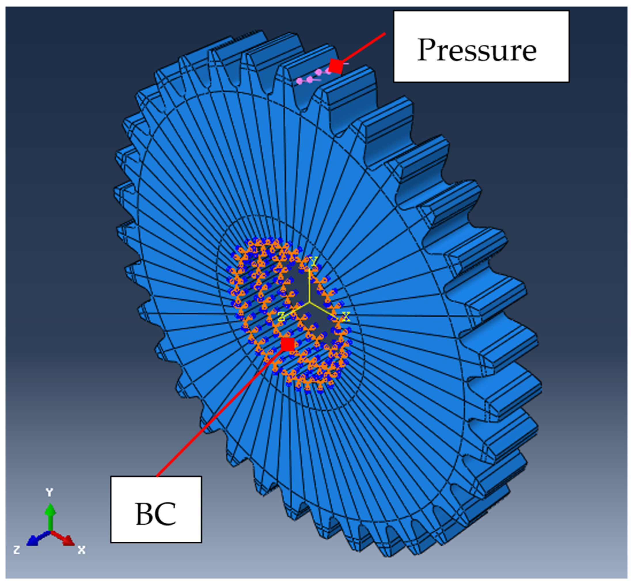
2.1. Numerical Model

The spur gear discussed in this article has a 2.5 mm module, 34 teeth, a pressure angle of 200, and a gear width of 10 mm. A gear hub diameter of 25 mm was taken into account. Accordingly, the nominal torque can be determined at around 200 Nm. A 3D geometric model of the gear with an involute tooth profile was created in KISSsoft [33], while the numerical model was prepared in Abaqus/CAE [34]. The modulus of elasticity for Ti-6Al-4V was E = 206,000 MPa, and the Poisson ratio was ν = 0.3. The gear was partitioned and meshed with 2,918,412 linear hexahedral elements. These elements are of the C3D8 type and are 8-node linear brick elements with first-order shape functions. The base element size was 1 mm, with local mesh refinement applied in the gear-tooth region to capture higher stress gradients and geometric detail. A relatively fine mesh was employed overall to support subsequent topology optimization. Hexahedral elements were selected for their inherent geometric symmetries, which positively influence the symmetry and structural quality of the optimized design.
Since the gear has 34 teeth, the pressure load was applied to both flanks of each tooth, resulting in 68 load cases—one for each side of each tooth. As seen in Figure 1, the first pressure load was applied on the right side of the tooth flank in the first load case; this pressure load was only active in this load case. The second pressure load was then applied to the left side of the same tooth. The process was repeated for all 34 teeth, influencing the final topology, as optimization is carried out for each load case.
A pressure load of 618 MPa was applied to a tooth flank, as shown in Figure 1. This pressure was applied to both sides of the tooth flank due to the planned topology optimization. Additionally, the hub surface was fixed in all free directions, as shown in Figure 1.

2.2. Topology Optimization

The numerical gear model was prepared in Abaqus/CAE, and the resulting input file was transferred to CAESS ProTOp 6.2 [20] for additional configuration and optimization. The gear body was configured as a design domain to allow for the replacement of the full solid body design by a lattice structure, while the gear hub and toothed ring were defined as fixed domains; thus, they remain unchanged during the design and optimization process. According to Harl et al. [35], topology optimization of the lattice structure differs from conventional topology optimization. In the present study, two different types of lattice cell were employed to configure the gear-body structure. Both lattice cells, a cube, and a plane diagonal were designed in a cylindrical coordinate system. A detailed explanation of the lattice design parameters can be found in [36]. The research was primarily focused on the design process of a lattice structure and topology optimization, which was thoroughly addressed, including model preparation by specifying free and fixed design domains. This research focuses on the manufacturing and experimental validation of the lattice-structure gear. Furthermore, a novel device was conceived, designed, and produced for this purpose.
The initial lattice structure was obtained by designing some potential lattice structures with different design parameters and by examining their initial stresses. The lattice structure with an acceptable stress level was defined as initial structure. This initial structure was then optimized by employing topology optimization. Figure 2 depicts the von Mises stress distribution of the gears used in this study. The initial lattice structure of the gear body and its von Mises stress distribution are shown in color mapping in Figure 2a. The lattice structure was then optimized; the von Mises stress distribution is presented in Figure 2b. The stress distribution for the solid gear body was also analyzed and is presented in Figure 2c.
The initial gear model had a maximum stress of about 590 MPa at the tooth root, while the peak stress within the lattice structure was approximately 400 MPa, as shown in yellow in Figure 2. In order to reduce stress concentrations, especially within the lattice structure, topology optimization was applied. As a result, the volume of the initial model increased from 41.2% to 49.3%, which drastically reduced the peak stress within the lattice structure to approximately 150 MPa. Furthermore, the stresses in the tooth area also decreased to around 550 MPa.
The increased thickness of the optimized lattice structure compared to the initial structure results from the higher material volume and the incorporation of additional finite elements during the optimization process. Each optimization cycle involved adding and removing finite elements to and from the structure. An uneven surface accumulates stress, which leads to mechanical deformation, while a smoother surface ensures better stress distribution. Therefore, the lattice structure was subjected to surface smoothing, as shown in Figure 3.

3. Gear Manufacturing

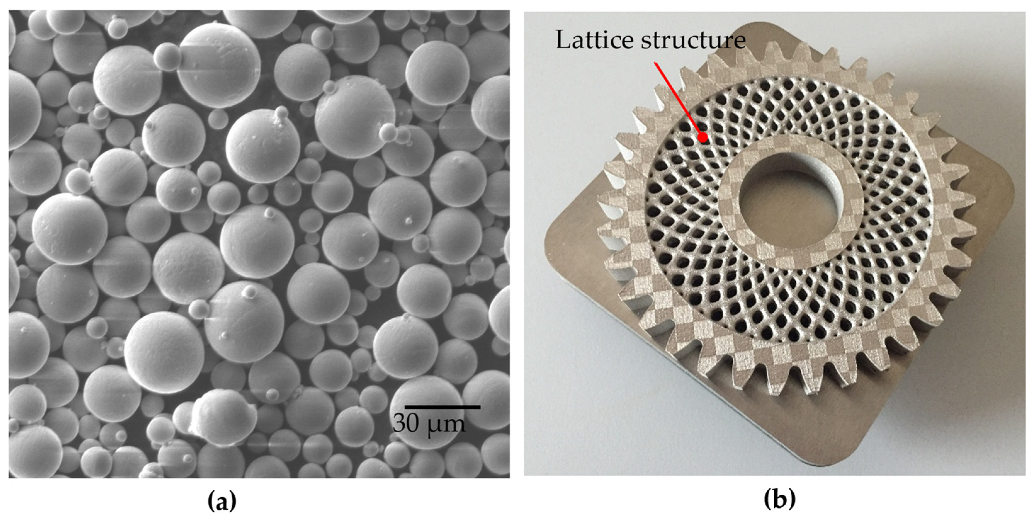
3.1. Material Selection

The gear was manufactured using spherical powder particles of Ti-6Al-4V alloy with a diameter between 10 µm and 40 µm. The powder was supplied by Dentaurum GmbH & Co. KG, Ispringen, Germany. The elemental composition of the powder particles is presented in Table 1, and a scanning electron microscope (SEM) image of the powder particles is shown in Figure 4a.
The traditional manufacturing process has its limitations in the production of complex designed products and from the point of view of material properties such as a high melting point, low thermal conductivity, and high chemical affinity. In the current research, a cellular lattice structure was designed and manufactured with Ti-6Al-4V considering the above-mentioned material properties [37,38,39]. This means that it is difficult to produce such a gear product using conventional manufacturing processes. In this respect, additive manufacturing (AM) is the most promising manufacturing process. In electron beam melting (an AM process), parts are manufactured in a vacuum environment, but the powder material must be exposed in air during powder loading [40]. According to the manufacturers, SLM is the most suitable process among AM technologies for the production of metal parts [41]. The SLM process also enables a protective environment from the moment the powder container is opened, which protects against exposure to air. Therefore, in this study, a lattice-structured Ti-6Al-4V gear was manufactured using the SLM process.

3.2. Effects of Manufacturing Parameters

The mLaB from Concept Laser, Germany, was used as the SLM machine to manufacture the part. The SLM machine was integrated with a Yb:glass fiber supplied by IPG, Germany. The machining chamber was filled with argon to keep the oxygen content below 0.4% by volume. After investigating various metallurgical properties, such as density, pore properties, tensile properties, and the hardness of the Ti-6Al-4V samples manufactured by SLM, the best manufacturing parameters for fabricating the gear were determined [42].
The scanning speed has the greatest influence on the thermal gradient and the properties of the melt pool in the SLM process, especially for Ti-6Al-4V [43] Therefore, the scanning speed was varied in a wide range between 150 mm/s and 1000 mm/s to determine the best possible manufacturing parameters for the fabrication of such gears with a large scanning area per powder layer. High scanning speeds led to an insufficient volume of the melt pools and, thus, to a higher number of unmelted zones. On the other hand, a lower scanning speed led to a high energy density in the powder bed, which reduced the viscosity and evaporation of the melt [44]. As a result, a high number of melt splashes occurred, causing material loss in the scanning zones. Therefore, both high and low scanning speeds resulted in a lower product density.
In addition, the high scanning speed caused a thermal shock due to rapid heating and cooling, which led to a high thermal gradient in the fabricated part during SLM. On the other hand, a high ED also led to a high thermal gradient and residual stress in the layers that were already fabricated during SLM. However, the moderate scanning speed, i.e., 600 mm/s, led not only to considerable density but also to the highest strength of the samples [43]. Therefore, the best combination of manufacturing parameters was a 75 W laser power, 600 mm/s scanning speed, and 0.077 mm hatch spacing for a 52 µm layer thickness. This combination of fabrication parameters resulted in a density of 4.405 g/cm3, which corresponds to a relative density of 99.45, and the parts contained nearly spherical pores with a size of less than 20 µm. Therefore, this sample also exhibited improved tensile properties, including a tensile strength of 1250 MPa and a yield strength of 1030 MPa. The hardness of the part is also quite high, at 390 HV, to ensure high wear resistance in the gear tooth.

3.3. Manufacturing Build-Up Direction

The build-up direction plays an important role in achieving better mechanical properties (taking into account the load direction) and the safe manufacture of the part, especially with such a large-volume part. The different orientation of the part in the SLM machining chamber to produce the part resulted in different build directions and scan areas for each layer. The orientation can lead to different overhanging areas and bottom layers. The overhanging areas may require support beams. On the other hand, both cause a higher surface roughness. In addition, a larger scanning area for one layer leads to higher thermal stress on the solidified part during fabrication.
A part with a large difference between major and minor axes, such as a gear, results in large differences in thermal gradient generation, overhanging area, bottom-layer area, required powder volume, manufacturing time, and inert gas cost during manufacturing [45]. To reduce these, a proper orientation was required in this study. However, since the build chamber and powder feed chamber are fixed in the SLM machine used in this study, the major axis of the gear was aligned horizontally to reduce the powder volume and argon cost. However, surface roughness was also considered in this study—specifically, the roughness of the tooth flanks rather than the datum faces. The vertical surface in the SLM process provides a much better surface compared to the bottom surface. Orienting the gear with horizontal reference surfaces resulted in a vertical alignment of the tooth flanks. On the other hand, the vertical alignment of the datum face leads to a high proportion of start or bottom layers where scanning should begin on the powder bed. This can lead to the formation of a high surface roughness over a large area.
Although the manufacture of the gear in a horizontal position with horizontal datum faces has disadvantages due to the formation of a high thermal gradient, this orientation was considered in order to reduce material costs and increase the smoothness of the tooth flanks. However, the thermal gradient and the formation of residual stress can be minimized by a suitable combination of laser manufacturing parameters. Therefore, a balance between mechanical properties, surface roughness, and the formation of residual stress during manufacturing is required to fabricate the part well. After the results of surface roughness, product density, pore properties, strength, and hardness were determined, a specific combination of manufacturing parameters was considered for the fabrication of the gear.

3.4. Gear Fabrication Problems

A large-volume part accumulates high levels of thermal stress and residual stress that lead to bending and delamination of layers during manufacture. Accumulated residual stress can be so high that a 6 mm thick Ti-6Al-4V build tray can be bent by tearing M4 screws, which has been observed in previous studies [42]. The small (approx. 100 µm) bending-up phenomenon can lead to a remelting of the layers and subsequently cause a lack of material or an excess amount of material, which eventually causes burning or insufficient melting of this portion, respectively.
After several experiments on gear manufacturing, the final gear was manufactured by keeping its one face on the build tray without any support, as shown in Figure 4b. This setup was used for the subsequent experiments in this study. In addition, the thickness of the build tray was increased to protect it from bending.

3.5. Post Processing

During the fabrication of the gear, the gear body was brought into contact with the build tray and separated using the wire EDM (Electrical Discharge Machining) process. The gear was also sandblasted to remove the loose powder particles adhering to the surface and to smooth the surface. However, the datum faces and tooth flanks were ground and polished to reduce test noise. The gear body with the lattice structure was not ground, as it is a challenge to grind and polish it and observe the actual effects on the results of further tests.

3.6. The Final Gear Product

The final volumes of the solid gear and the printed gear were 51,130 mm3 and 32,570 mm3, respectively, which represents a reduction of about one-third due to the lightweight lattice structure. This significant decrease indicates the effectiveness of the lattice structure and the optimization process in reducing the overall mass of the gear while maintaining structural integrity.
It is decisive to emphasize that the approach used in this work for a gear with a lattice structure, including its design, optimization, and manufacturing, can also be applied to other types of gears, such as helical gears and bevel gears. The gear must be large enough to accommodate the insertion of a lattice structure into its body. For different gear sizes, the lattice structure may need to be adjusted based on the overall mechanical load. Different pressure loads can be considered, and based on the specific loading conditions, topology optimization can be performed. Additionally, different materials can be selected for gear manufacturing depending on the application conditions.

4. Strain Measurement System Development and Results

4.1. Test Rig Development

To measure the strain of the fabricated solid body, as well as the lattice-structure gear, a test rig was created specifically for this research project. The components of the test-rig system and their assembled form are shown in Figure 5. The components of the test rig were produced and assembled. The test rig enabled to the measurement of the strain at the gear tooth, ring, and hub in this study but not acceleration or sound pressure measurement. It has a compact design with a stiff frame consisting of heavy steel blocks and connecting shafts. The 63007-2RS1 bearings (provided by SKF, Gothenburg, Sweden) for the shafts are positioned inside the steel blocks so that the tested gears can be replaced without removing the bearings. The electric motor that drove the test rig had a power of 0.34 kW, and the speed was adjusted via a frequency controller.
The closed loop essentially consists of two shafts coupled by a pair of drive gears on the left side and a pair of test gears on the right side of the test rig. One shaft contains a torsion spring, and the other contains a clutch. The clutch was opened while the torque was applied with a plain digital torque wrench. Inside the torque application device was a CSK35 one-way clutch bearing to ensure the specified torque. The clutch was then closed, and the torque application device was removed from the test rig, leaving the torque in the closed loop.

4.2. Experimental Setup for Strain Measurement

The experimental setup for strain measurement in a spur gear is shown in Figure 6. It consists of a test rig, NI USB 6255 and NI SCXI 1314 data acquisition devices (both were provided by National Instruments Corp. Austin, TX, USA) and TML 1-11 3L strain gauges (provided by Tokyo Measuring Instruments Laboratory Co., Ltd., Tokyo, Japan) and slip ring MZ060-S20 (provided by Moflon Technology, Shenzhen, China). The drive gears are positioned on one side of the blocks, while the tested gears are positioned on the other side, where the gauges were glued in different places to capture the signals when the gear rotates.
As shown in Figure 7, the gauges were affixed to the cleaned and polished surfaces of the tested gear at certain positions using a suitable adhesive, then connected to the slip ring. The gauges were wired to the rotating part of the slip ring, which rotates with the tested gears. The stationary part, on the other hand, remains fixed while they are in gold–gold contact. While the gears were loaded in the closed loop, the recorded signals were transmitted to the D/A converter and, finally, to the data acquisition and computer for signal analysis.
To evaluate the suitability of the lattice structure, the strain of two pairs of gears was measured. Thus, two solid gears were considered as pairs to determine the strain, which is used as a reference in Figure 7a. The other pair consisted of a lattice-structure gear and a solid gear, as shown in Figure 7b. For both gears, the strains on the ring and hub were recorded in the radial and tangential directions. The strain was also recorded at the tooth root to detect localized stress concentrations. The torque applied during the test was 60 Nm, with the gear rotating at 310 rpm. The total duration of the measurement was 0.95 s.

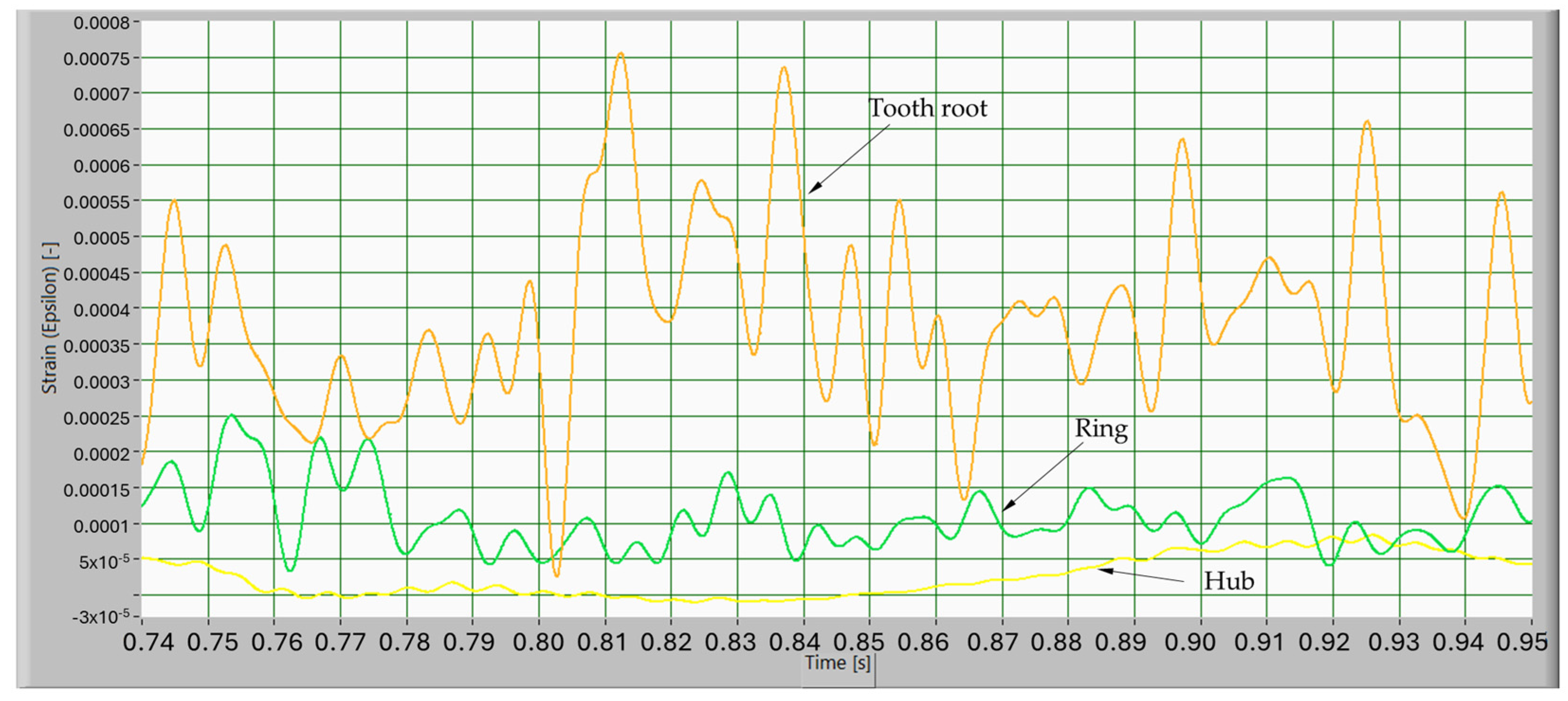
4.3. Strain on the Solid-Body Gear

The radial strain results for the solid over time are presented in Figure 8. Strains on three parts—namely, the tooth root, ring, and hub of the solid gear—are plotted in three different curves. The measurements are shown from 0.74 s to 0.95 s. The results show that the strain on the tooth root is significantly high compared to the ring and hub portions. On the other hand, the strain on the ring is comparatively higher than on the hub. In addition, the radial strain of the solid gear does not remain stable over time.
The strains in the tangential direction in the solid gear over time are shown in Figure 9. The results show that the strain is not stable over time when the pressure is applied in the tangential direction. However, as shown in Figure 8 and Figure 9, the strain in the tangential direction is higher than the strain in the radial direction, which is due to the phenomenon of the tangential and radial load difference.

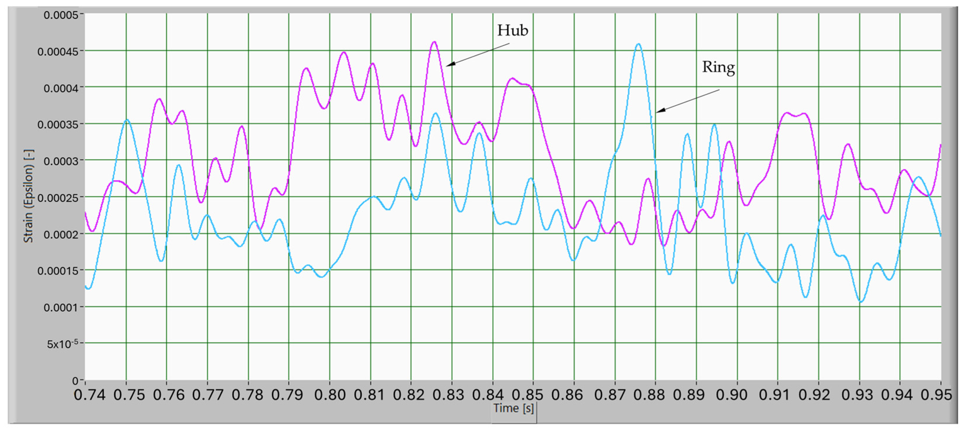
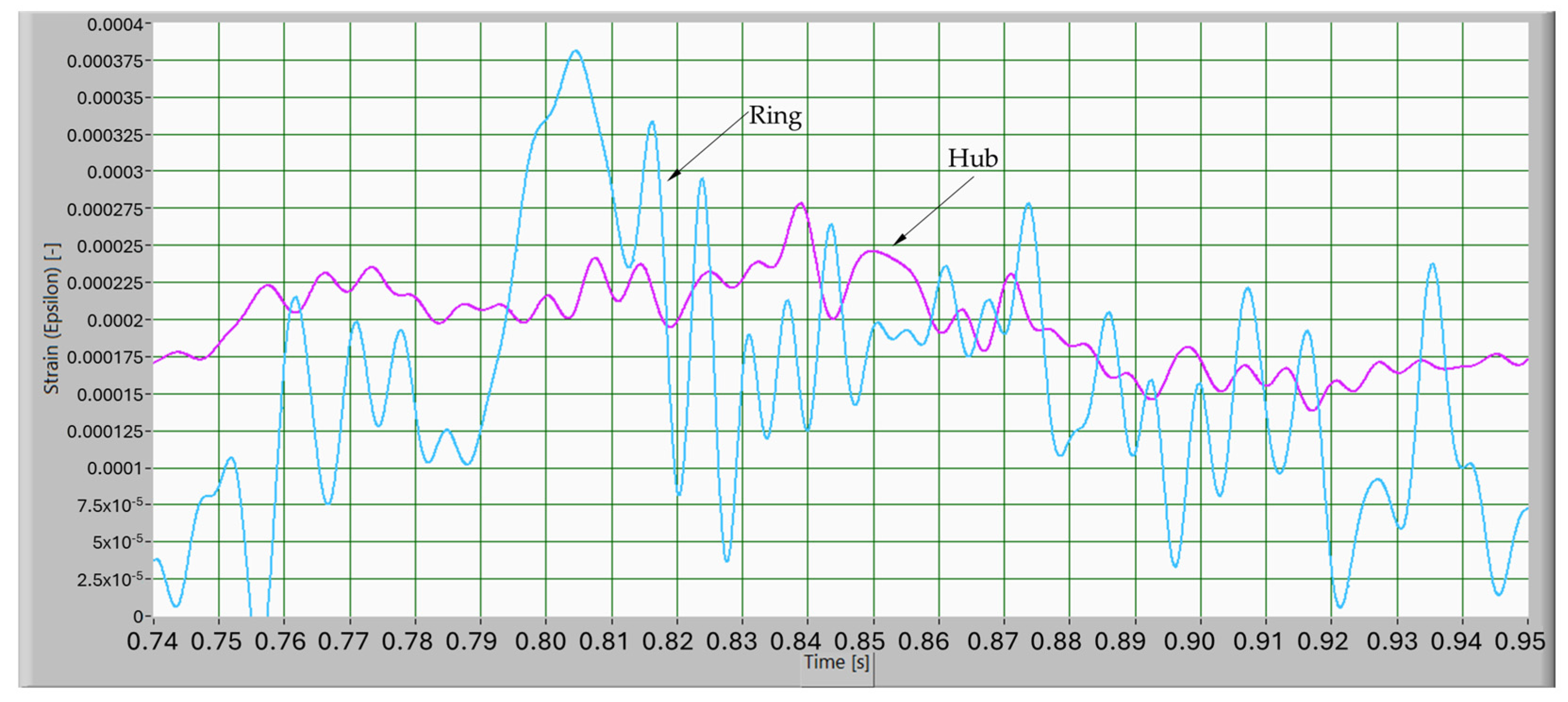
4.4. Strain on the Lattice-Structure Gear

The results of the radial strains over time for the lattice-structure gear are shown in Figure 10. Strains on three parts—namely, the tooth root, ring and hub of the lattice-structure gear—are plotted in three different curves. The measurements are shown from 0.74 s to 0.95 s. The results show that the strain on the tooth root is significantly higher compared to the ring and hub portions. On the other hand, the strain on the ring is comparatively higher than on the hub. In addition, the strain on the hub is stable and lower in the radial direction of the lattice structure. This phenomenon occurs because the structure is flexible, resulting in a lower variable load transmitted from the gear ring to the hub.
The strains on the lattice-structure gear in the tangential direction over time are shown in Figure 11. When the pressure was applied in the tangential direction, the strain on the ring was not stable over time. A comparison of the strain on the lattice-structure gear, as illustrated in Figure 10 and Figure 11, reveals that the radial strain is less than in the tangential direction. Therefore, for both solid and lattice-structure gears, the tangential load is higher than the radial load, which fulfils the phenomenon of stress distribution.
In order to assess the effects of the lattice structure on the overall mechanical behavior, the strain recorded in the hub area must be compared for both tested gears. If the radial strain of the two tested gears is compared (Figure 8 and Figure 10), it becomes clear that the radial strain of the printed gear is lower and stable, with no fluctuations over time. If one also compares the strain of the two tested gears in the tangential direction (Figure 9 and Figure 11), it becomes clear that the strain of the printed gear at the hub is lower and more stable over time. It is clear that the lattice structure has a significant influence on strain reduction, especially on the gear hub.

5. Conclusions

A spur gear made of Ti-6Al-4V with an optimized lattice structure was manufactured using the SLM process. The lattice structure was optimized by topology optimization, which minimized stress concentrations and ensured mechanical strength. This gear was then used for experimental strain measurements during operation. To facilitate these measurements, a new test rig was developed to record strains in multiple directions.
In order to achieve the smoothest possible surface of the gears and to minimize manufacturing costs and time, the gears were manufactured with horizontal surfaces. This led to an increase in the laser scanning area for each successive layer, resulting in the accumulation of a high thermal gradient in the manufactured part. This led to the bending and destruction of some layers, damaging the manufactured gear. Increasing the thickness of the build plate and manufacturing the gear by placing one side on the build plate without using support beams eventually led to good gear manufacturing.
Strain measurements for both tested gears in different positions showed that the lattice structure exhibited significantly lower strains. This reduction is attributed to the optimized lattice geometry, which improves the stress distribution during operation. The lattice structure not only reduces the mass of the gear but also contributes to a more uniform performance by minimizing mechanical strain.
To achieve the required dimensional accuracy and surface finish, the tooth flanks and hub of the printed gear must be machined using a grinding process, which is an additional post-processing step.

Author Contributions

Conceptualization, R.R. and S.P.; methodology, R.R., S.P. and A.B.; validation, R.R. and J.P.; investigation, R.R. and S.P.; writing—original draft preparation, R.R. and S.P.; writing—review and editing, A.B. and J.P.; supervision, J.P. All authors have read and agreed to the published version of the manuscript.

Funding

This research was funded by research project funding from the University of Prishtina, Erasmus Mundus JoinEU-SEE PENTA, and CAESS company. The authors thank the Center of DfAM, University of Prishtina, Kosovo, for supporting this research (Grant No. USGP2024/25GR3). The authors also thank the Slovenian Research Agency for funding this research (Grant Nos. P2-0137, P2-0157, J1-2470, J1-2471, J1-4416, J7-4636, J7-50226, J7-50227, J1-60015, and J7-60120).

Data Availability Statement

The data that support the findings of this study are available from the authors upon request.

Conflicts of Interest

The authors declare no conflicts of interest.

References

  1. Czerwinski, F. Current trends in automotive lightweighting strategies and materials. Materials 2021, 14, 6631. [Google Scholar] [CrossRef]
  2. Zhu, L.; Li, N.; Childs, P.R.N. Light-weighting in aerospace component and system design. Propuls. Power Res. 2018, 7, 103–119. [Google Scholar] [CrossRef]
  3. Hopkins, N.; Jiang, L.; Brooks, H. Energy consumption of common desktop additive manufacturing technologies. Clean. Eng. Technol. 2021, 2, 100068. [Google Scholar] [CrossRef]
  4. Benkert, T.; Hiller, M.; Volk, W. Multi-component lightweight gearwheels with deep-drawn wheel body for automotive applications. J. Phys. Conf. Ser. 2017, 896, 012083. [Google Scholar] [CrossRef]
  5. Wei, J.; Zhang, A.; Shi, L.; Qin, D.; Lim, T.C. Modeling and dynamic characteristics of planetary gear transmission in non-inertial system of aerospace environment. J. Mech. Des. Trans. ASME 2020, 142, 031103. [Google Scholar] [CrossRef]
  6. Andary, F.; Berroth, J.; Jacobs, G. An Energy-Based Load Distribution Approach for the Application of Gear Mesh Stiffness on Elastic Bodies. J. Mech. Des. Trans. ASME 2019, 141, 095001. [Google Scholar] [CrossRef]
  7. Gu, X.; Velex, P.; Sainsot, P.; Bruyère, J. Analytical investigations on the mesh stiffness function of solid spur and helical gears. J. Mech. Des. Trans. ASME 2015, 137, 063301. [Google Scholar] [CrossRef]
  8. Hu, Z.; Tang, J.; Chen, S.; Lei, D. Effect of mesh stiffness on the dynamic response of face gear transmission system. J. Mech. Des. Trans. ASME 2013, 135, 071005. [Google Scholar] [CrossRef]
  9. Faggioni, M.; Samani, F.S.; Bertacchi, G.; Pellicano, F. Dynamic optimization of spur gears. Mech. Mach. Theory 2011, 46, 544–557. [Google Scholar] [CrossRef]
  10. Ghosh, S.S.; Chakraborty, G. On optimal tooth profile modification for reduction of vibration and noise in spur gear pairs. Mech. Mach. Theory 2016, 105, 145–163. [Google Scholar] [CrossRef]
  11. Ma, H.; Pang, X.; Feng, R.; Wen, B. Evaluation of optimum profile modification curves of profile shifted spur gears based on vibration responses. Mech. Syst. Signal Process. 2016, 70, 1131–1149. [Google Scholar] [CrossRef]
  12. Yang, J.; Zhang, Y.; Lee, C.H. Multi-parameter optimization-based design of lightweight vibration-reduction gear bodies. J. Mech. Sci. Technol. 2022, 36, 1879–1887. [Google Scholar] [CrossRef]
  13. Shweiki, S.; Palermo, A.; Mundo, D. A Study on the Dynamic Behaviour of Lightweight Gears. Shock Vib. 2017, 2017, 7982170. [Google Scholar] [CrossRef]
  14. Xiao, W.; Huang, Y.; Jiang, H.; Jin, L. Effect of powder material on vibration reduction of gear system in centrifugal field. Powder Technol. 2016, 294, 146–158. [Google Scholar] [CrossRef]
  15. Xiao, W.; Li, J.; Wang, S.; Fang, X. Study on vibration suppression based on particle damping in centrifugal field of gear transmission. J. Sound Vib. 2016, 366, 62–80. [Google Scholar] [CrossRef]
  16. Li, S. Experimental investigation and FEM analysis of resonance frequency behavior of three-dimensional, thin-walled spur gears with a power-circulating test rig. Mech. Mach. Theory 2008, 43, 934–963. [Google Scholar] [CrossRef]
  17. Iandiorio, C.; Mattei, G.; Marotta, E.; Costanza, G.; Tata, M.E.; Salvini, P. The Beneficial Effect of a TPMS-Based Fillet Shape on the Mechanical Strength of Metal Cubic Lattice Structures. Materials 2024, 17, 1553. [Google Scholar] [CrossRef]
  18. Iandiorio, C.; Milani, D.; Salvini, P. Optimal Uniform Strength Design of Frame and Lattice Structures. Comput. Struct. 2024, 301, 107430. [Google Scholar] [CrossRef]
  19. Dong, G.; Tang, Y.; Li, D.; Zhao, Y.F. Design and optimization of solid lattice hybrid structures fabricated by additive manufacturing. Addit. Manuf. 2020, 33, 101116. [Google Scholar] [CrossRef]
  20. CAESS ProTOp. Available online: www.caess.eu (accessed on 12 March 2025).
  21. Dong, G.; Tang, Y.; Zhao, Y.F. A survey of modeling of lattice structures fabricated by additive manufacturing. J. Mech. Des. Trans. ASME 2017, 139, 100906. [Google Scholar] [CrossRef]
  22. Xiao, Z.; Yang, Y.; Xiao, R.; Bai, Y.; Song, C.; Wang, D. Evaluation of topology-optimized lattice structures manufactured via selective laser melting. Mater. Des. 2018, 143, 27–37. [Google Scholar] [CrossRef]
  23. Maconachie, T.; Leary, M.; Lozanovski, B.; Zhang, X.; Qian, M.; Faruque, O.; Brandt, M. SLM lattice structures: Properties, performance, applications and challenges. Mater. Des. 2019, 183, 108137. [Google Scholar] [CrossRef]
  24. Condruz, M.R.; Badea, T.A.; Paraschiv, A. Compressive Behavior of Inconel 625 and Ti-6Al-4V Strut Lattices Fabricated by LPBF. Appl. Sci. 2024, 14, 11909. [Google Scholar] [CrossRef]
  25. Sambo, A.M.; Younas, M.; Njuguna, J. Insights into Machining Techniques for Additively Manufactured Ti6Al4V Alloy: A Comprehensive Review. Appl. Sci. 2024, 14, 10340. [Google Scholar] [CrossRef]
  26. Cuesta, I.I.; Díaz, A.; Rojo, M.A.; Peral, L.B.; Martínez, J.; Alegre, J.M. Parameter Optimisation in Selective Laser Melting on C300 Steel. Appl. Sci. 2022, 12, 9786. [Google Scholar] [CrossRef]
  27. Arun, A.P.; Giriraj, B.; Rahaman, A.F. Gear test rig—A review. Int. J. Mech. Mechatron. Eng. 2014, 14, 16–26. [Google Scholar]
  28. Uctu, O.; Sevim, I. Investigation of parallel axis gear test rigs and selection criterias to design. In Proceedings of the 2017 8th International Conference on Mechanical and Aerospace Engineering, ICMAE 2017, Prague, Czech Republic, 22–25 July 2017. [Google Scholar] [CrossRef]
  29. Abruzzo, M.; Beghini, M.; Santus, C.; Manconi, S. Dynamic behavior of a power re-circulating gear test rig including periodic variation of mesh stiffness and static transmission error. Mech. Mach. Theory 2021, 159, 104247. [Google Scholar] [CrossRef]
  30. Patil, C.M.; Pingale, A.D. Measurement of Gear Stiffness of Healthy and Cracked Spur Gear by Strain Gauge Technique. Int. J. Mech. Eng. 2018, 5, 9–15. [Google Scholar] [CrossRef]
  31. Raghuwanshi, N.K.; Parey, A. Experimental measurement of gear mesh stiffness of cracked spur gear by strain gauge technique. Measurement 2016, 86, 266–275. [Google Scholar] [CrossRef]
  32. Dai, H.; Chen, F.; Xun, C.; Long, X. Numerical calculation and experimental measurement for gear mesh force of planetary gear transmissions. Mech. Syst. Signal Process. 2022, 162, 108085. [Google Scholar] [CrossRef]
  33. KiSSsift Hirnware. Available online: https://www.kisssoft.com/en (accessed on 2 March 2025).
  34. Abaqus/CAE 6.14 User’s Guide. Available online: http://62.108.178.35:2080/v6.14/books/usi/default.htm (accessed on 13 February 2025).
  35. Harl, B.; Predan, J.; Gubeljak, N.; Kegl, M. On configuration-based optimal design of load-carrying lightweight parts. Int. J. Simul. Model. 2017, 16, 219–228. [Google Scholar] [CrossRef]
  36. Ramadani, R.; Belsak, A.; Kegl, M.; Predan, J.; Pehan, S. Topology Optimization Based Design of Lightweight and Low Vibration Gear Bodies. Int. J. Simul. Model. 2018, 17, 92–104. [Google Scholar] [CrossRef]
  37. Textor, M.; Sittig, C.; Frauchiger, V.; Tosatti, S.; Brunette, D.M. 7 Properties and Biological Significance of Natural Oxide Films on Titanium and Its Alloys; Springer: Berlin/Heidelberg, Germany, 2001. [Google Scholar]
  38. Boivineau, M.; Cagran, C.; Doytier, D.; Eyraud, V.; Nadal, M.-H.; Wilthan, B.; Pottlacher, G. Thermophysical properties of solid and liquid Ti-6Al-4V (TA6V) alloy. Int. J. Thermophys 2006, 27, 507–529. [Google Scholar] [CrossRef]
  39. Pegues, J.; Roach, M.; Williamson, R.S.; Shamsaei, N. Surface roughness effects on the fatigue strength of additively manufactured Ti-6Al-4V. Int. J. Fatigue 2018, 116, 543–552. [Google Scholar] [CrossRef]
  40. Moosa, A.U.; Hernández-Nava, E.; Mejbel, M.K.; Todd, I. The joining of CP-vanadium and Ti–6Al–4V using the Electron Beam Melting Additive Manufacturing method. Adv. Ind. Manuf. Eng. 2022, 5, 100102. [Google Scholar] [CrossRef]
  41. Ponticelli, G.S.; Tagliaferri, F.; Venettacci, S.; Horn, M.; Giannini, O.; Guarino, S. Re-Engineering of an Impeller for Submersible Electric Pump to Be Produced by Selective Laser Melting. Appl. Sci. 2021, 11, 7375. [Google Scholar] [CrossRef]
  42. Ramadani, R.; Pal, S.; Kegl, M.; Predan, J.; Drstvenšek, I.; Pehan, S.; Belšak, A. Topology optimization and additive manufacturing in producing lightweight and low vibration gear body. Int. J. Adv. Manuf. Technol. 2021, 113, 3389–3399. [Google Scholar] [CrossRef]
  43. Gu, Q.; Li, H.; Yang, Z.; Zhang, Y.; Liu, X.; Li, G. Microstructure and Phase Transformation Temperature of NiTiNb Shape Memory Alloy Prepared by Laser Solid Forming Using Mixed Powder. Appl. Sci. 2022, 12, 2371. [Google Scholar] [CrossRef]
  44. Mayoral, N.; Medina, L.; Rodríguez-Aparicio, R.; Díaz, A.; Alegre, J.M.; Cuesta, I.I. Process Parameter Optimisation in Laser Powder Bed Fusion of Duplex Stainless Steel 2205. Appl. Sci. 2024, 14, 6655. [Google Scholar] [CrossRef]
  45. Paolino, D.S.; Tridello, A.; Fiocchi, J.; Biffi, C.A.; Chiandussi, G.; Rossetto, M.; Tuissi, A. VHCF Response up to 109 Cycles of SLM AlSi10Mg Specimens Built in a Vertical Direction. Appl. Sci. 2019, 9, 2954. [Google Scholar] [CrossRef]
Figure 1. Spur gear with fixing hub, partitions, and applied load.
Applsci 15 07949 g001
Figure 2. Von Mises stress distribution of (a) the initial lattice structure, (b) the optimized lattice structure, and (c) the solid-body gear.
Applsci 15 07949 g002
Figure 3. Smoothing of the lattice structure.
Applsci 15 07949 g003
Figure 4. Manufacturing elements: (a) SEM image of the Ti-6Al-4V powder particles used to fabricate the gear; (b) photograph of the fabricated gear.
Applsci 15 07949 g004
Figure 5. The layout of the test rig with a closed loop.
Applsci 15 07949 g005
Figure 6. Experimental setup for strain measurement.
Applsci 15 07949 g006
Figure 7. The tested gears with attached strain gauges: (a) solid body gear; (b) lattice-structure gear.
Applsci 15 07949 g007
Figure 8. The radial strain signals of the solid-body gear over time.
Applsci 15 07949 g008
Figure 9. The strain signals of the solid gear over time when pressure is applied in the tangential direction.
Applsci 15 07949 g009
Figure 10. The radial strain signals of the lattice-structure gear over time.
Applsci 15 07949 g010
Figure 11. Strain signals over time with pressure is applied in the tangential direction of the lattice-structure gear.
Applsci 15 07949 g011
Table 1. Elemental composition of the Ti-6Al-4V powder material used to fabricate the gear.
ElementWt.%
TiBalanced
Al6
V4
N<0.1
C<0.1
H<0.1
Fe<0.1
O<0.1
Disclaimer/Publisher’s Note: The statements, opinions and data contained in all publications are solely those of the individual author(s) and contributor(s) and not of MDPI and/or the editor(s). MDPI and/or the editor(s) disclaim responsibility for any injury to people or property resulting from any ideas, methods, instructions or products referred to in the content.

