Article

Cable-Driven Exoskeleton for Ankle Rehabilitation in Children with Cerebral Palsy

by
Iñaki Dellibarda Varela
1,
Pablo Romero-Sorozabal
1,
Gabriel Delgado-Oleas
1,2,
Jorge Muñoz
1,
Álvaro Gutiérrez
3,* and
Eduardo Rocon
1
1
Centro de Automática y Robótica, Consejo Superior de Investigaciones Científicas (CSIC-UPM), 28500 Madrid, Spain
2
Ingeniería Electrónica, Universidad del Azuay, Cuenca 010107, Ecuador
3
ETSI Telecomunicación, Universidad Politécnica de Madrid (UPM), 28040 Madrid, Spain
*
Author to whom correspondence should be addressed.
Appl. Sci. 2025, 15(14), 7817; https://doi.org/10.3390/app15147817
Submission received: 26 May 2025 / Revised: 30 June 2025 / Accepted: 9 July 2025 / Published: 11 July 2025
(This article belongs to the Special Issue Advances in Cable Driven Robotic Systems)

Abstract

Featured Application

The use of Cable-Driven Parallel Robots for the development of exoskeletons for gait rehabilitation has great potential due to the control they allow over movements and the flexibility they give to patients.

Abstract

Cerebral palsy is the leading cause of motor disability in early childhood, with no curative treatment currently available. To mitigate its effects and promote motor rehabilitation, robotic-assisted therapies have emerged as a complement to conventional physiotherapy. In particular, cable-driven exoskeletons offer notable advantages, providing patients with additional mobility and interaction with their environment while preserving motion assistance. Within this context, the Discover2Walk project introduces a modular cable-driven robotic platform designed for early-stage gait rehabilitation. This article presents a novel ankle control module capable of actuating 3 degrees of freedom: 2 translational (in the x and z directions) and 1 rotational (dorsiflexion/plantarflexion). Experimental results confirm the technical feasibility of the approach and its effectiveness in guiding motion within the targeted degrees of freedom.

1. Introduction

Cerebral palsy (CP) is a non-progressive neurological disorder originating from damage to the upper motor neurons of the central nervous system (CNS). It is the most prevalent neuromotor condition in newborns, with an incidence of 2–2.5 per 1000 live births [1]. Although the primary brain injury is non-degenerative, its symptoms often lead to a range of secondary impairments, including spasticity, movement dysfunctions, cognitive deficits, language disorders, or epilepsy [2]. Notably, the loss of ambulatory ability is strongly associated with a decline in both health status and overall quality of life [3].
In addition to its health consequences, CP imposes a substantial economic burden on both healthcare systems and families. Costs increase markedly with the severity of the condition, underscoring the need for effective therapeutic interventions [4].
Neurodevelopmental treatments remain a cornerstone of CP management to reduce quality of life. These focus on muscle tone, reflex activity, abnormal movement patterns, postural control, and perceptual-cognitive functions [1]. Among these, physiotherapy is the most widely adopted approach due to its demonstrated efficacy in improving functional outcomes [3].
In recent years, the use of exoskeletons has emerged as a promising complement to conventional therapies in the treatment of CP [5]. The use of these robotic devices in combination with physiotherapy has proven to have great benefits, as opposed to the isolated use of physiotherapy or surgery, which in the long run can lead to problems in maintaining patients’ muscle strength over a prolonged period of time [6].
Exoskeletons enable repetitive, task-specific training aimed at enhancing neuroplasticity. Active functional training has been shown to improve both motor skills and muscular strength in children with CP [7]. Furthermore, these devices support passive movements and promote autonomous exploration of the environment, contributing to both physical and cognitive development. This form of intervention—commonly referred to as robot-assisted therapy—relies on medical robotic devices to deliver targeted physical rehabilitation [8,9].
Rigid exoskeletons represent the traditional approach in assistive robotics. These devices are designed to provide full or partial body weight support, making them suitable for patients with severe mobility impairments who cannot stand or walk independently. By employing structured, predefined movement trajectories, they facilitate controlled gait patterns that closely resemble natural human walking. Their rigid structure ensures stability and controlled joint moments, enabling children with motor impairments to engage in independent ambulation while maintaining biomechanical alignment and safety [10,11].
One of the leading examples of a rigid exoskeleton is ATLAS 2030 (Marsi Bionics, Spain) [12,13], an advanced pediatric exoskeleton designed for gait rehabilitation in children with CP. It features 8 actuated degrees of freedom (DOFs), with four per leg allowing for hip, knee, and ankle rotations in the sagittal plane, along with hip rotation in the frontal plane. It has an adjustable stiffness mechanism, which minimizes impact forces, enhances user safety, and efficiently stores and releases energy through passive elastic elements. Additionally, the exoskeleton’s geometry can be customized to match the child’s body dimensions, with adjustable joint limits, ensuring a more personalized and effective rehabilitation process [12]. ATLAS 2030 has been shown to significantly improve gross motor function, range of motion (ROM), and spasticity reduction when integrated into conventional therapy. It has emerged as a promising tool for facilitating greater mobility, independence, and overall quality of life in children with motor impairments [13].
Currently, the most studied exoskeleton for gait rehabilitation is Lokomat (Hocoma, Norwell, MA, USA). This robotic gait orthosis is designed for intensive locomotion therapy and features actuated hip and knee joints that guide the user’s legs along predefined trajectories while walking on a treadmill. The system includes a dynamic body weight support (BWS) mechanism that gradually reduces support as the patient progresses, allowing for a more natural gait pattern [14]. By combining robotic assistance with a treadmill, Lokomat enables high-repetition, task-specific gait training under controlled conditions, optimizing movement patterns while reducing the physical strain on therapists [15]. Additionally, the system provides real-time biofeedback through a visual interface, enhancing patient engagement and motor learning. Studies have demonstrated significant improvements in gait speed, balance, and walking endurance, particularly in patients with neurological impairments such as stroke and CP. However, while Lokomat training enhances locomotion parameters, its effects on functional independence and overground walking ability remain comparable to those of conventional physiotherapy, highlighting the need for individualized rehabilitation approaches [16].
Despite demonstrating a positive impact for gait rehabilitation scenarios, these robotic devices are rigid and heavy structures that limit the subject’s freedom of movement and, in some cases, introduce significant inertia in their joints [17]. For this reason, in recent years, exosuits have been developed as lighter structures that are better adapted to the patient’s morphology compared with rigid exoskeletons. In exosuits, weight support relies entirely on the patient and their skeletal structure, reducing the device’s weight and minimizing movement restrictions through the use of fabric harnesses and low-profile actuation systems [18]. Exosuits tend to sacrifice some efficiency in power transmission to the user in exchange for greater comfort, allowing for prolonged use, reducing the inertia introduced by rigid exoskeletons on the human body, and improving metabolic efficiency [19].
One of the main examples of exosuits is the ReStore (ReWalk Robotics, Israel). It is designed as a robotic lower-limb exoskeleton that assists locomotion by providing support for hip and knee flexion and extension, enabling individuals with spinal cord injuries, post-stroke hemiplegia, and other mobility impairments to walk with assistance [20]. In addition to supporting walking, ReWalk allows users to transition between sitting, standing, and walking postures, enhancing its functional applicability in rehabilitation settings [21]. Studies have demonstrated its effectiveness in improving mobility and post-stroke rehabilitation, as well as its ability to reduce the metabolic cost of walking, making ambulation more efficient for users [20]. Furthermore, research on the ReWalk ReStore exosuit confirms its safety, reliability, and clinical feasibility in post-stroke rehabilitation, with a reduction in adverse events following individualized device adjustments and training [20]. A multi-site clinical trial demonstrated that, after just 5 days of training with the ReStore, participants significantly increased both their assisted and unassisted walking speeds, highlighting its potential to enhance gait recovery [22].
While exosuits offer a novel and promising direction in assistive rehabilitation, they are fundamentally limited by their reliance on wearable interfaces for force transmission. These systems require continuous and secure physical contact with the user’s body to actuate motion effectively, which can compromise comfort, restrict natural movement, and hinder voluntary motor exploration.
As an alternative, exoskeletons based on Cable-Driven Parallel Robots (CDPRs) have emerged to address these limitations. Unlike wearable exosuits, CDPR systems externalize actuation by using lightweight cables to apply forces remotely, minimizing the mechanical load on the user. These systems typically involve minimal attachment to the user, where the assisted joints are treated as an end effector [23], enhancing comfort and preserving a greater degree of natural interaction [24]. Recent studies confirm that CDPR-based exoskeletons can provide task-specific, controlled assistance that supports neuroplasticity and motor recovery, especially in populations with motor impairments such as stroke or cerebral palsy [25]. Moreover, end-effector-based lower-limb rehabilitation platforms have demonstrated outcomes that match or surpass those of traditional rigid exoskeletons in terms of safety, usability, and clinical efficacy [26,27]. These findings underscore the potential of cable-driven systems as a robust and user-friendly alternative for robotic gait rehabilitation.
The disruptive and innovative nature of CDPR-based exoskeletons has led to the emergence of several models in recent years [23]. One of the most documented and popular models is the CAREX-7 exoskeleton. This 7-degrees-of-freedom (DOF) cable-driven arm exoskeleton is designed to provide both translational and rotational assistance for upper-limb rehabilitation. Unlike traditional rigid exoskeletons, CAREX-7 employs lightweight cables to transmit forces, reducing inertia and allowing for a more natural interaction with the human arm [28]. The system consists of multiple cuffs attached to the shoulder, upper arm, forearm, and hand, enabling precise assistance and dexterous motion training while minimizing joint misalignment [26]. With its innovative wrench-field control strategy, CAREX-7 can dynamically adjust assistance levels based on the user’s needs, promoting functional motor recovery and rehabilitation [28]. Other examples of cable-actuated exoskeletons are CAFE, a 3-degrees-of-freedom robotic exoskeleton designed for hand rehabilitation following stroke [29]; exoskeleton for human rehabilitation by Zhang et al., which is a fully actuated parallel cable-driven exoskeleton designed for shoulder rehabilitation, utilizing antagonistic cable pairs to enhance stability and motion control [24]; and Diego exoskeleton (Tyromotion, Austria), an electromechanical device designed for upper-limb rehabilitation, providing arm gravity compensation to assist patients in unilateral or bilateral arm movements, enabling three-dimensional movements of the shoulder joint, and integrating virtual reality training to enhance patient engagement during therapy [25,30,31].
Although cable-actuated exoskeletons have had great development during the last decade in upper-limb rehabilitation, development for lower-limb and gait rehabilitation is much less documented and widespread. A remarkable work is the one developed by Barbosa et al., an exoskeleton designed for populations with gait impairments such as CP or stroke. This robot is composed of a frame with a variable number of cables (from one to six) and controls movement over the hip, knee, and ankle [32]. Of note also is the one developed by Li et al., a cable-driven parallel motion platform designed to help patients with waist injuries perform rehabilitation exercises. The system provides flexion/extension, adduction/abduction, and internal/external rotation of the waist by controlling cable tension [33]. Another relevant example is the ankle rehabilitation robot by Li et al. [34], which uses a CDPR mechanism to guide a mobile platform for ankle mobilization. However, this system is intended for isolated joint training in static conditions, and not for use during gait.
Among the most promising recent developments is the cable-driven Lower limb Rehabilitation Exoskeleton (C-LREX) [35,36], a conceptual robotic platform that uses four cables to control the leg in 3 degrees of freedom. It enables hip abduction/adduction and flexion/extension of the hip and knee, allowing the execution of full-leg rehabilitation trajectories toward healthy gait patterns. Although still under simulation, the system has demonstrated strong potential in terms of control accuracy and future clinical applicability.
Probably, the system most comparable to the exoskeleton presented in this paper is the one developed by Wu et al. [37,38]. This cable-actuated exoskeleton, developed over the last decade, is built upon a prismatic frame with motors anchored to it, which actuate cables to assist ankle motion during the swing phase in adult patients with incomplete spinal cord injury. The system aimed to increase walking speed and endurance, and included a pelvic support structure for partial body weight unloading. Ankle guidance was provided via two cables per leg. After several weeks of rehabilitation sessions, the system demonstrated substantial potential to enhance walking ability in the tested participants.
This paper presents a novel CDPR-based exoskeleton for gait rehabilitation in children with CP. The project is based on the Discover2Walk (D2W) exoskeleton (see Figure 1) [39], a modular, cable-actuated robotic platform designed for pediatric gait rehabilitation in the early stages of CP. As an end-effector-type robot, The D2W transmits forces from distal interfaces via lightweight cables to the patient’s joints, rather than placing actuators directly at the joints [26]. This innovative design enables young children to develop mobility and explore their surroundings at an age comparable to their peers without CP [39].
Within the D2W exoskeleton, we will focus on the design and implementation of a new ankle control module. The system consists of four brushless motors, each driving a dual-coil drum that simultaneously winds and unwinds two cables, enabling precise control of their lengths and end-effector position. The main motivation behind the design of the new ankle control module is to develop a new configuration that allows for controlling 3 DOFs: 2 translational (Cartesian x and z axes) and 1 rotational ( p i t c h rotation in Euler angle notation). This represents an improvement over the original D2W system, which was only capable of controlling translational motions. The implementation of the new system is due to feedback from clinicians associated with the D2W project, who highlighted the importance of being able to control dorsiflexion and plantarflexion rotations ( p i t c h rotation). The objectives pursued by the new ankle control module are the following:
  • Develop a new ankle control module that is capable of guiding ankle movement in 3 DOFs (x and z translations and p i t c h rotation) by mimicking healthy human gait patterns.
  • Make sure to restrict unwanted abduction and adduction rotations of the ankle (lateral rotation of the ankle).
  • Ensure the modular character of the exoskeleton for easy implementation and communication with the global D2W system.
  • Implement the Assistance-as-Needed (AAN) model that combines robotic actuation with the patient’s effort and ability to move for the correct performance of movements during rehabilitation (to be detailed more specifically in Section 2.2.4).
  • To carry out the experimental validation of the prototype with a CP patient to ensure its safety and ability to guide the movements of interest. This would lead, if successful, to the start of the clinical validation process of the prototype.
The main contribution of this paper is the development and validation of a novel cable-driven exoskeleton for ankle rehabilitation in children with CP. This exoskeleton, integrated within the D2W modular robotic platform, introduces an innovative ankle control module capable of guiding ankle motion in 3 degrees of freedom: 2 translational (x and z Cartesian directions) and 1 rotational (dorsiflexion and plantarflexion). Unlike existing solutions, this approach enhances patient mobility and interaction with their environment while guiding the patient’s movement. The system is designed to be lightweight, adaptable, and compatible with AAN strategies, enabling a more natural and personalized rehabilitation process. Experimental validation with a healthy subject demonstrates the feasibility, safety, and accuracy of the proposed module, setting the foundation for future clinical trials with CP patients.
The rest of the document is organized as follows: Section 2 (Exoskeleton Development and Control Methodology) outlines the modular structure of the D2W (with its three clearly differentiated modules), its bio-inspired control architecture implemented in ROS2, the mechanical and electronic structure of the new ankle control module, the kinematic models required for its implementation, and its control system. Section 3 (Results) presents the experiments performed on the exoskeleton and the results obtained. These results will be discussed in Section 4 (Discussion), as well as the future of the project. Finally, Section 5 (Conclusions) concludes the paper with a summary of the project and its results.

2. Exoskeleton Development and Control Methodology

In this section, a comprehensive overview of the engineering principles behind the Discover2Walk (D2W) platform is presented. The modular design—comprising the pelvic, ankle, and treadmill modules—is described in detail, emphasizing how each component contributes to the system’s overall functionality. The integration of a bio-inspired control architecture within a ROS2 framework enables distributed, real-time coordination across modules. Particular attention is given to the development of the novel ankle control module, covering its mechanical design, electronic integration, and the associated kinematic modeling. Finally, the section introduces the control strategies implemented to achieve precise, multi-degrees-of-freedom assistance during gait rehabilitation.

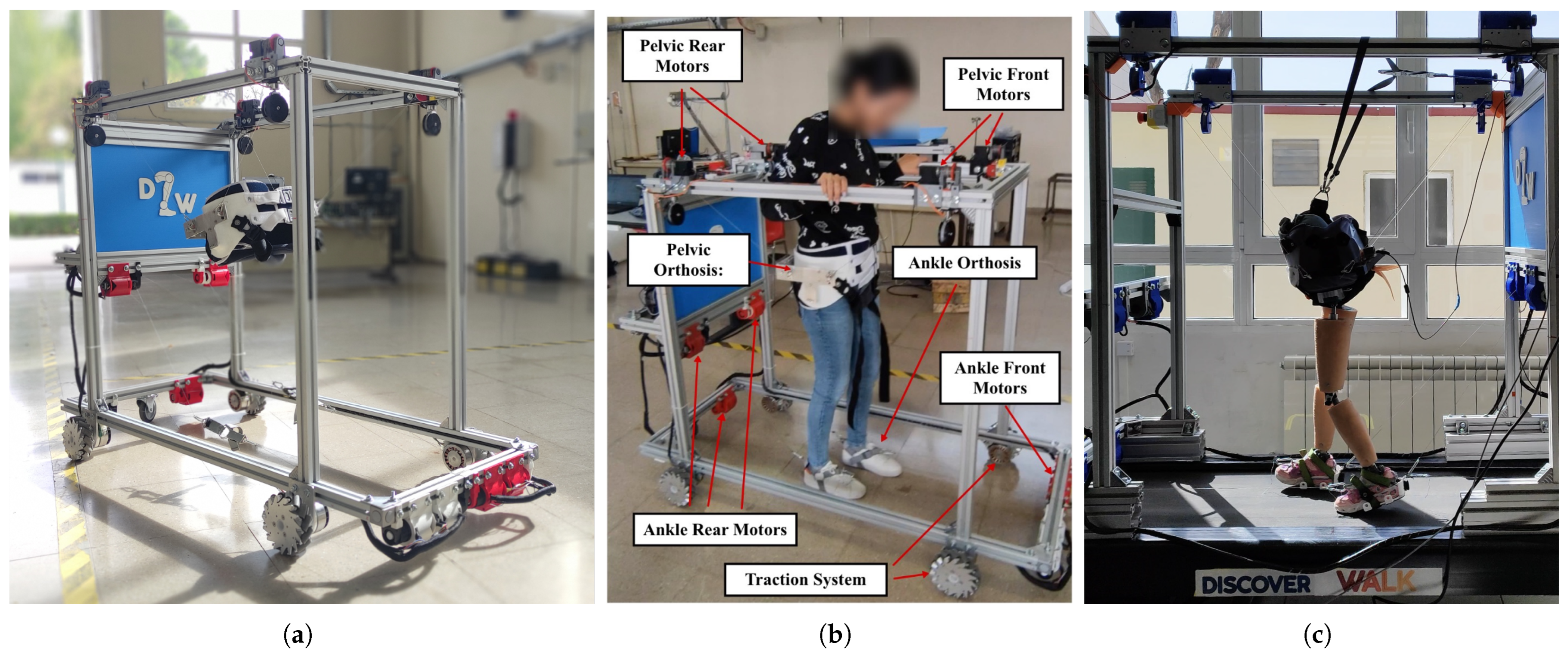
2.1. Discover2Walk Overview

The D2W (see Figure 1) features a flexible structure that adapts easily to the child’s morphology, allowing guided movement along three-dimensional trajectories tailored to the patient’s characteristics, but with a high degree of freedom. In other words, unlike rigid exoskeletons, the D2W does not restrict the child’s freedom of movement, enabling them to explore their motor skills and interact with the surrounding environment. Additionally, the inertia introduced by the robot is significantly lower than that of rigid exoskeletons. The D2W is specifically designed to treat children between the ages of 2 and 5 years [40].
The Discover2Walk is composed of three modules (see Figure 2) that act independently, but are coordinated and communicated with each other to perform a joint action [41]. The three modules are pelvic module, ankle module, and traction module. Communication and coordination between the elements of the system are achieved through a bio-inspired architecture that mimics the action of the CNS [41].

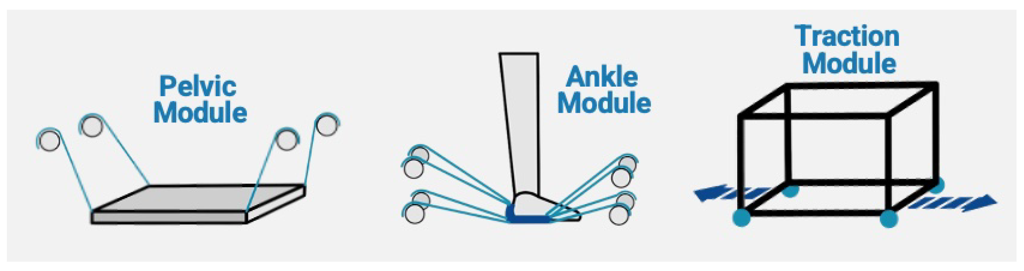
2.1.1. Pelvic Module

The pelvic module consists of a suspended CDPR designed to provide body weight support and assist the pelvic motion during the gait cycle. The patient’s pelvis is supported by a modified commercial hip orthosis (PRIM, Madrid, Spain), which functions as the system’s EE. To enhance structural rigidity and prevent the deformation of the original plastic components, the orthosis is reinforced with two additional rigid metallic elements.
Each Kevlar cable of the CDPR is independently actuated by a Dynamixel XH540-W150-T servomotor (ROBOTIS, Corona, CA, USA) mounted at the top vertices of the Discover2Walk (D2W) prismatic frame. The system integrates multiple sensors to ensure accurate control and safe operation, as follows:
  • Inertial measurement unit (IMU): allows the monitoring of the pelvis angular position, velocity, and linear acceleration. The model used is BNO055 IMU (BoschSensortec, Reutlingen, Germany).
  • Motor absolutes encoders: to measure the length of the cables. The model used is AMT102-V encoders (CUI Devices, Oswego, OR, USA).
  • Load cells: to control partial body weight support. The model used is DYMH-103 load cells with a maximum capacity of 20 kg (CALT Sensor, Shanghai, China).

2.1.2. Ankle Control Module

The ankle module allows the control of 2 DOFs, both translational in the longitudinal and vertical directions of gait (Cartesian axes x and z). In this section, we will briefly describe the operation of the previous system and the reason to be replaced by the new module to be described later.
The module uses 3 Dual Shaft Motor-D6374 150KV brushless motors (ODrive Robotics, Sunnyvale, CA, USA) per ankle, 6 motors in total. Each of the motors has an associated AMT102-V encoder (CUI Devices, USA), which, as in the pelvis module, allows the length of the cables to be controlled. Each motor acts on a Kevlar cable, which in turn connects to commercial foot straps (SYL Fitness, La Mesa, CA USA).

2.1.3. Traction Control Module

The traction module can vary between two possible configurations depending on the space available for rehabilitation exercises. The first option consists of a mobile traction system consisting of four omnidirectional wheels that allow the platform to be moved around the room (see Figure 1a,b). These wheels are made of aluminum and have a diameter of 254 mm and a load capacity of 40 kg each (Nexus Robot, Hongkong, China). To assist the movement, each wheel is powered by an EC 90 Flat 600 W brushless motor (MAXON, Sachseln, Switzerland).
The second possibility is to replace the wheels with a treadmill (see Figure 1c). This configuration is more appropriate for situations where limited space is available for rehabilitation.

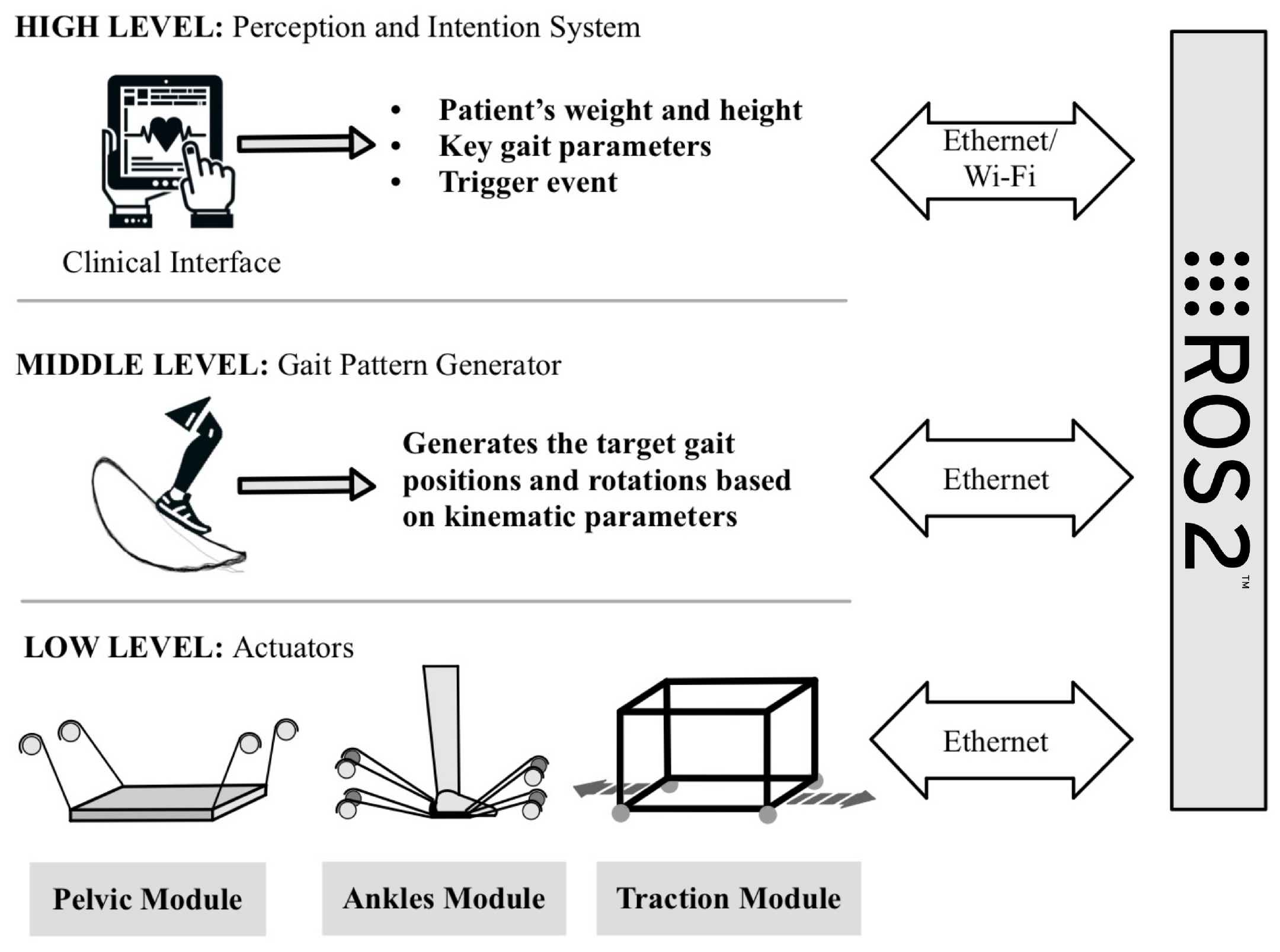
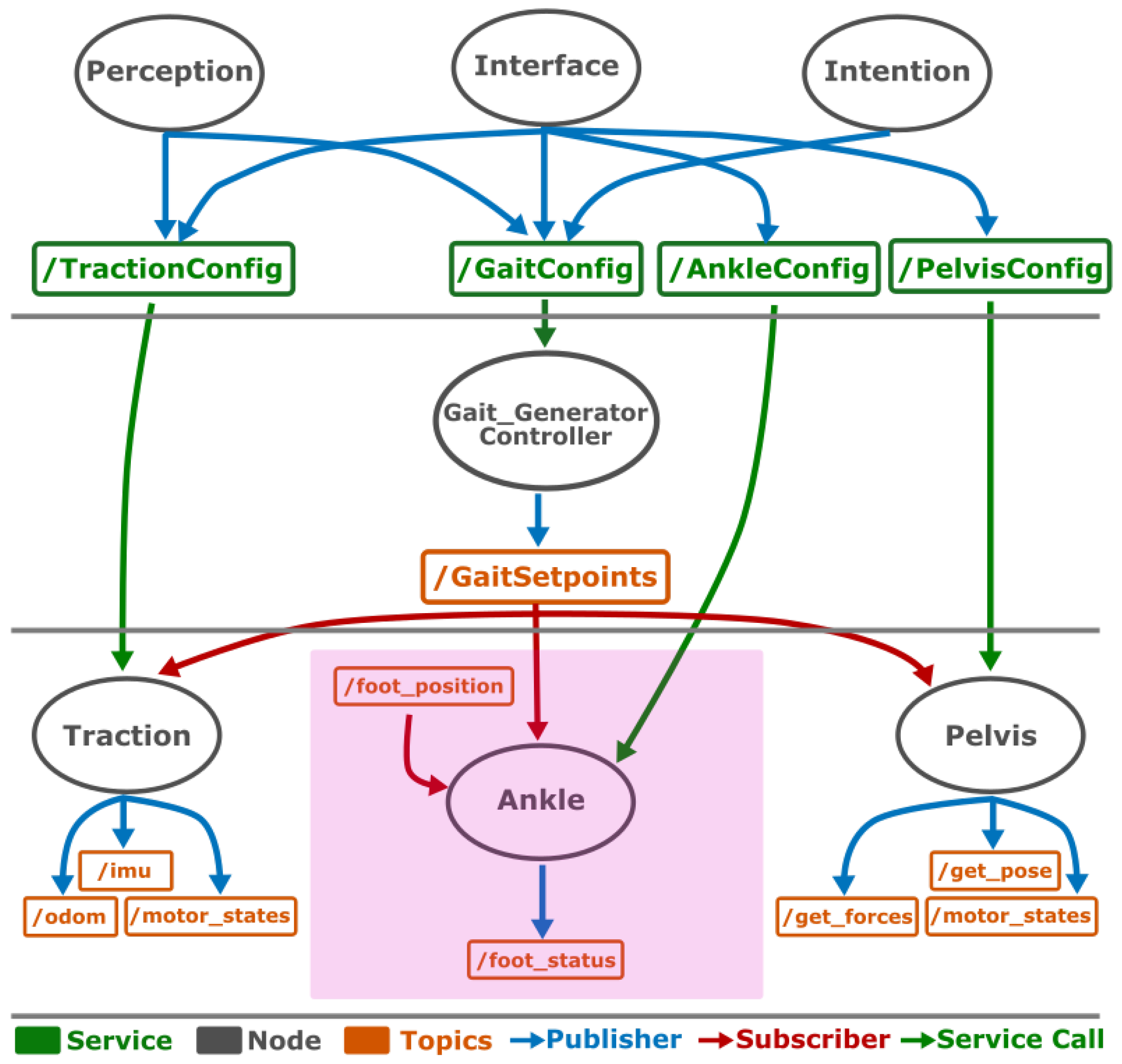
2.1.4. Bio-Inspired Architecture

The communication and control of the different modules of the D2W system is achieved by implementing a bio-inspired architecture (see Figure 3). This architecture mimics the hierarchical functioning of the CNS, the processing of information, and commands from the human body for the movement of the lower body. We have three intercommunicating levels of complexity [41]: high, medium, and low level.
  • High level: it is the one associated with the processes of perception and intention. It is implemented through a clinical interface that modifies the parameters of the exoskeleton according to the anthropometric conditions of the patient (height and weight) and uses a trigger event to initialize the movement.
  • Medium level: based on the parameters determined at the high level and the sensor readings of the subject’s movement, it is responsible for generating the gait patterns to be performed by the subjects [42]. These trajectories will be sent to the low level.
  • Low level: it is in charge of ensuring that each of the actuators of the three modules (pelvis, ankle, and traction) reaches the positions calculated by the middle level so that the trajectories are performed correctly. As in the human body, each actuator has sensors that send feedback to the middle level.
The implementation of the described system was carried out using ROS2 nodes, allowing modularity and communication between the different levels (see Figure 4).
At the top level, there is communication between the perception and intention algorithms and the ROS2 services, allowing the parameters to be modified at each level. The clinical graphical interface is implemented based on HTML and allows the platform to be configured to fit the therapeutic needs of each patient. In addition, the interface provides feedback from all nodes of the system.
At the high level, trigger events activate all nodes of the system. The event can be triggered from the interface manually, or by a brain–computer interface (BCI) with algorithms that process the cortical information. When a patient intends to perform a movement, the BCI detects the electrical activity generated by the brain and sends information to the exoskeleton to perform a preconfigured movement [43].
In the middle level appears the node associated with the gait pattern generator. This node uses the information received from the high-level services (patient height and gait speed) to generate the three-dimensional trajectories to be followed by each of the three platform modules in the form of setpoints [42].
Finally, at the low level, we find that each of the controlled kinematic groups (pelvis, ankle, and traction) is controlled by an independent node (achieving the modularity of the system). Each of these nodes will be in charge of sending position, velocity, and torque information to the actuators associated with its module. In addition, they will also publish the information measured by the system’s sensors in a number of topics.
The bio-inspired hierarchical control architecture implemented in the exoskeleton ensures a highly modular and scalable system, allowing for intuitive integration within rehabilitation environments. This architecture has demonstrated enhanced clinical usability, offering real-time monitoring, a user-friendly clinical interface, and seamless adaptability to individual patient needs, being that the operation of the system is completely transparent to the end user [40].

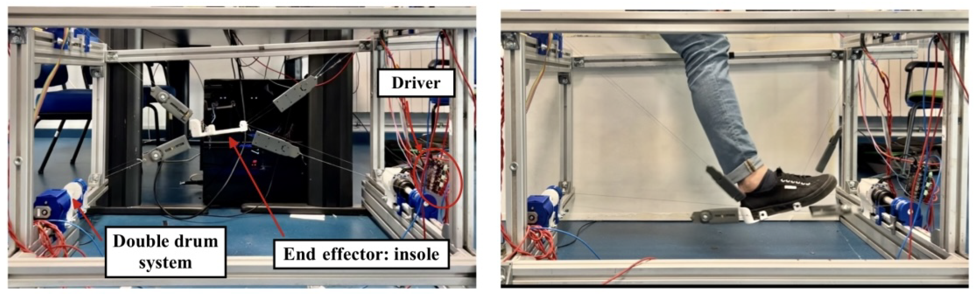
2.2. Novel Ankle CDPR Module

Initial clinical evaluations of the D2W revealed limitations in the original ankle actuation, particularly its inability to provide targeted assistance across key degrees of freedom involved in early gait development. Clinicians emphasized the need for a more versatile module capable of actuating not only ankle rotation but also translational movements essential for foot placement and load transfer. In response, a novel ankle control module was developed to address these requirements, enabling actuation in 3 degrees of freedom: longitudinal (x) and vertical (z) translations and p i t c h rotation corresponding to dorsiflexion and plantarflexion. This functionality is critical for modulating toe clearance, ground contact dynamics, and overall gait symmetry.
In this section, we present the design and implementation of this new module, detailing its mechanical structure, custom end effector, electronic integration, kinematic modeling, and control architecture.

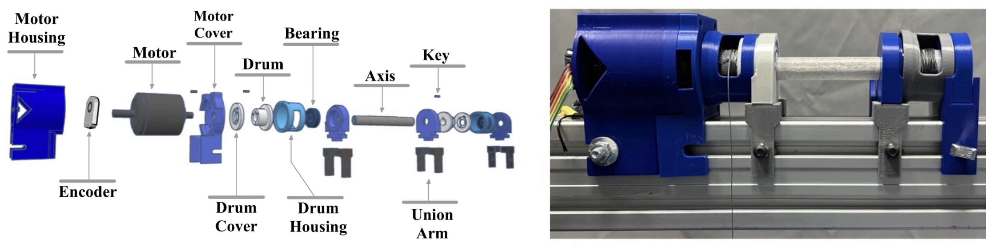
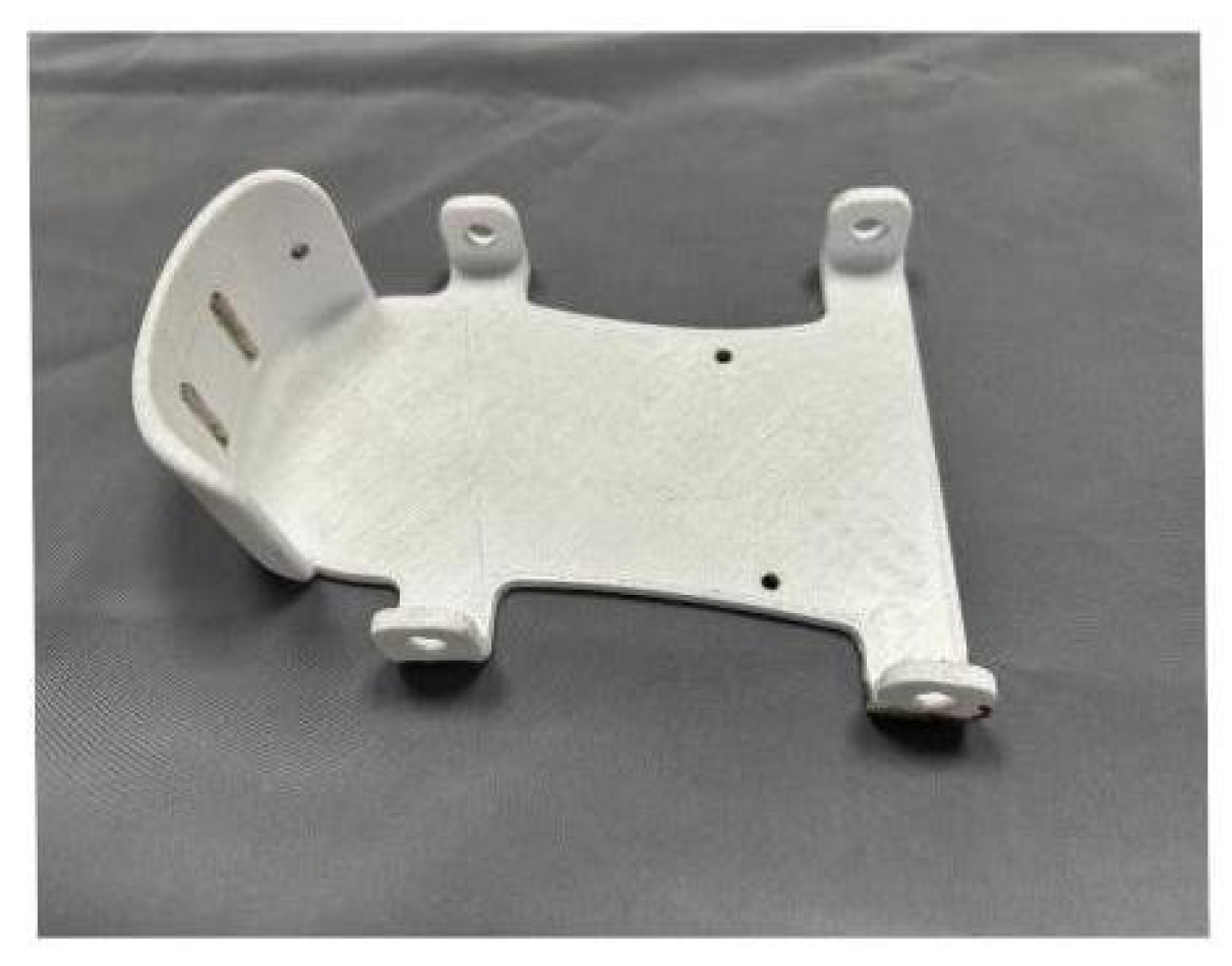
2.2.1. Mechanical System

The novel ankle module is also modeled as a CDPR (see Figure 5), with a prismatic rectangular aluminum shape with dimensions of 1020 × 580 × 680 mm covering the usual length of a child between 6 and 12 years old (450 and 600 mm) [44].
The new module is classified as a 1R2T CDPR, meaning that it is designed to actuate 1 rotational degree of freedom (R) and 2 translational degrees of freedom (T). This configuration adheres to the following relationship:
m + 1 = n
where m is the number of DOFs to be controlled and n is the number of wires required to do it [45]. Therefore, to control 3 DOFs, we will need four wires arranged in a sagittal plane.
A key design consideration of the novel module was the suppression of undesired abduction/adduction (lateral) ankle rotations. To achieve this, a mechanically redundant configuration with eight cables actuated by only four motors was implemented. Each motor simultaneously regulates the length of two mechanically linked cables, which increases the system’s stiffness in the lateral plane and improves directional control (see Figure 6).
An additional advantage of this redundant configuration is that it preserves the complete symmetry of the exoskeleton. This symmetrical layout ensures that the mechanical and kinematic principles governing Cable-Driven Parallel Robots (CDPRs) remain fully valid and applicable throughout the workspace, facilitating accurate modeling and control.
This is accomplished using custom-designed PLA mechanical components (Table 1). Each motor drives a pair of cable drums that are mechanically linked via a centrally aligned PET-printed shaft (180 mm in length), which ensures synchronized rotation and improves structural robustness. This assembly is rigidly mounted to the aluminum profile frame, resulting in a stable and modular mechanical foundation for the ankle module (see Figure 6).
Another alternative considered to the 1R2T configuration—featuring four motors controlling eight cables in a redundant setup—was the implementation of eight motors, each actuating a single cable. This would result in a full 3R3T configuration, enabling independent control over 3 translational and 3 rotational degrees of freedom. While potentially useful, this approach would provide control over DOFs that are not critical at the current stage, according to clinical expert review. Moreover, it would significantly increase the mechanical and computational complexity of the system, which led to its dismissal in favor of the simpler and more targeted 1R2T configuration.
To transmit motion to the patient’s ankle, a set interchangeable custom orthosis was developed in the form of a sole that interfaces directly with the foot. The sole includes four dedicated anchorage points for cable attachment, enabling effective control of the ankle’s degrees of freedom. To withstand mechanical loads, the sole was fabricated in PET, offering greater strength than the PLA used for other structural parts (excluding the central axis). This component serves as the system’s end effector and is illustrated in Figure 7.

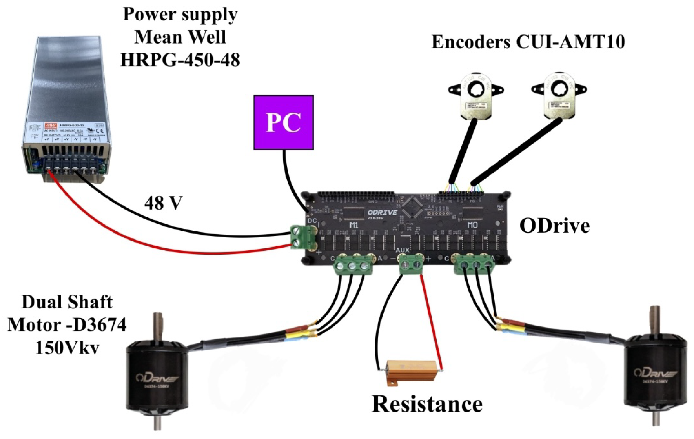
2.2.2. Electronic Architecture

The ankle module is controlled by a single-board computer running a Linux-based operating system with a PREEMPT-RT real-time patch, ensuring deterministic execution for time-sensitive control tasks. Communication with the actuation hardware is established via USB serial interface, connecting the computer to two motor drivers (ODrive Robotics, Sunnyvale, CA, USA)—one dedicated to the front motors and the other to the rear.
Each driver independently controls two brushless dual-shaft motors (D374, 150 KV, ODrive Robotics, USA). These motors are equipped with AMT10 incremental encoders (CUI Devices, USA), which provide high-resolution measurements of shaft rotation, enabling accurate estimation of cable lengths.
The entire system is powered by a 48 V DC power supply (model HRPG-450-48, Mean Well Enterprises Co., Taiwan), which delivers sufficient current for simultaneous multi-motor operation under dynamic loading conditions.
An overview of the electronic architecture corresponding to a single motor driver is presented in Figure 8. It should be noted that the complete system integrates two such drivers operating in parallel to control all four motors.

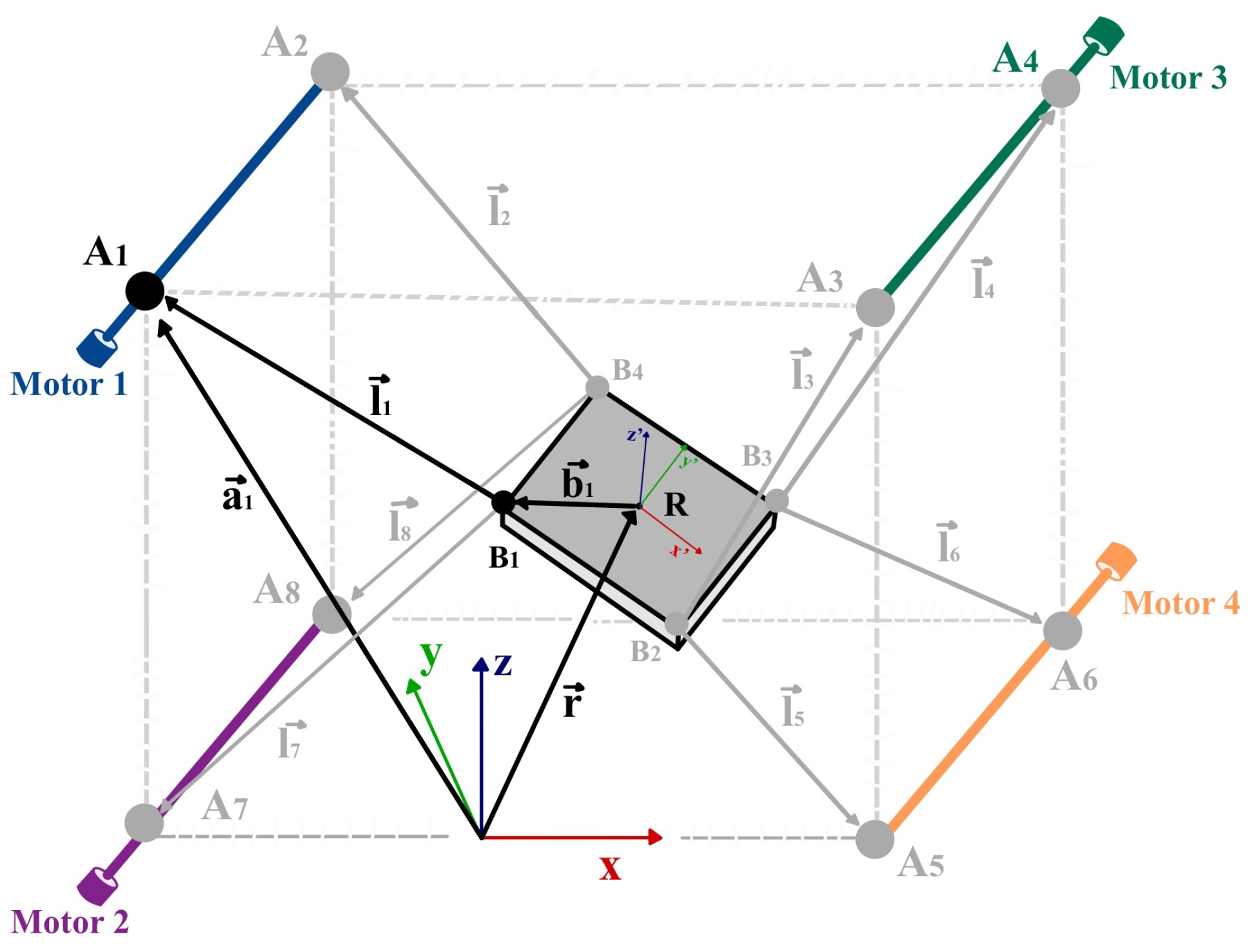
2.2.3. Kinematic Model

To enable accurate motion control of the ankle end effector, a kinematic model of the cable-driven system is required. This model establishes the relationship between the pose of the end effector—in terms of its position and orientation in space—and the lengths of the actuating cables. Given the system’s 1R2T configuration, the model must account for both translational motions along the longitudinal and vertical axes and rotational motion around the mediolateral axis ( p i t c h ). The kinematic formulation presented below serves as the basis for both the inverse kinematics required for control and the forward kinematics used for state estimation and validation.
Inverse Kinematics
The inverse kinematics function, denoted as φ I K , computes the required cable lengths from a desired pose of the end effector. Given the target position r and orientation R of the end effector in Cartesian space, the inverse kinematics maps these to the corresponding set of cable lengths l = [ l 1 , , l n ] according to
φ I K ( r , R ) = l
l i = l i = a i r R b i
R = R x ( roll ) · R y ( pitch ) · R z ( yaw )
r = ( x , y , z )
In this formulation, r R 3 is the Cartesian position of the end effector’s center relative to the exoskeleton’s fixed coordinate system {X, Y, Z}; R R 3 × 3 is the global rotation matrix defined by Euler angles roll, p i t c h , and yaw; a i is the position vector of the ith motor anchor point; and b i is the local position of the ith cable attachment point on the end effector, expressed in its local frame { X , Y , Z }. The geometric interpretation of these vectors is illustrated in Figure 9.
Since the mechanical structure of the platform and the positions of the motors are fixed, and the end effector is assumed to be rigid and inelastic, the inverse kinematic function φ I K enables the computation of the exact cable lengths required to guide the end effector to any desired pose during rehabilitation exercises.
Forward Kinematics
Conversely, the forward kinematics function, denoted as φ F K , estimates the pose of the end effector based on measured cable lengths. This is used primarily for evaluating the system’s tracking accuracy and performance.
Computing φ F K involves solving an overdetermined system derived from the geometric constraint that each cable defines a sphere centered at an anchor point a i with a radius l i . The intersection of these spheres determines the position and orientation of the end effector. The geometric formulation of the problem φ F K is illustrated in Figure 10.
To solve this system, a nonlinear least-squares optimization approach is adopted, minimizing the squared difference between the predicted and measured cable lengths, as follows:
ψ i ( l , r , R ) = a i r R b i 2 l i 2 = 0
Φ ( l ) = min i = 0 N 1 ψ i
Here, ψ i is the error function for the ith cable, and Φ ( l ) is the total objective function to be minimized. The values of r and R that minimize Φ are interpreted as the estimated position and orientation of the end effector at the given instant.
The forward kinematics function thus allows continuous pose estimation of the end effector using encoder measurements. This capability is essential for experimental validation, enabling accurate assessment of system performance and motion tracking during rehabilitation sessions.

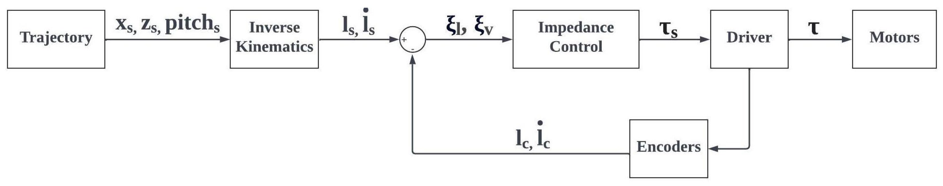
2.2.4. Control System
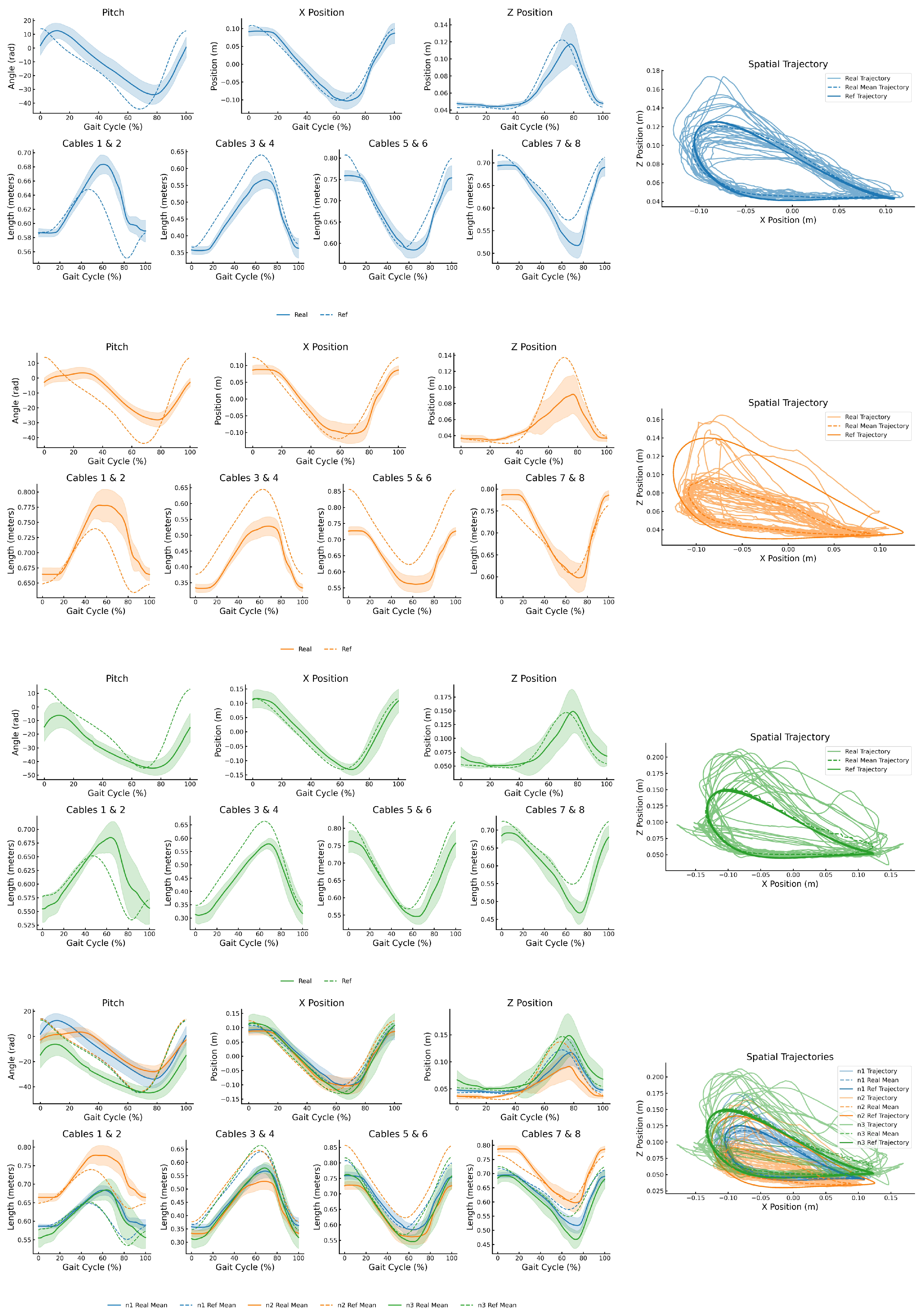
The control strategy of the ankle module is designed to implement the Assistance-as-Needed (AAN) paradigm [46], which aims to provide only the minimal robotic assistance required to correctly perform a task. Rather than imposing predefined trajectories, AAN-based systems continuously adapt to the user’s motion, promoting active participation. This approach has been shown to enhance movement accuracy, stimulate neuroplasticity, and improve motor learning, while also reducing therapy duration and cost [46,47,48].
It is important to note that, at this stage of development, the AAN control is not dynamically adaptive. While it enables guided movement by applying only the necessary assistance to promote muscular engagement and strengthening, its configuration must be performed offline by the clinician between therapy sessions.
To realize the AAN model, a mechanical impedance control strategy was adopted. Unlike classical position control, impedance control does not enforce trajectory tracking at all costs; instead, it modulates the actuator response by simulating a virtual spring-damper behavior. This reduces the risk of excessive forces and ensures safe physical interaction between the robot and the user—an essential consideration in pediatric neurorehabilitation.
The control loop, illustrated in Figure 11, computes the reference torque τ i applied to each motor according to the impedance law, as follows:
τ i = K S ξ l i + K D ξ v i
where K S and K D are the stiffness and damping coefficients, respectively, and ξ l i and ξ v i denote the length and velocity errors for the i-th cable.
The length error, ξ l , is defined as the difference between the desired cable length l s , derived via inverse kinematics, and the actual cable length l c measured by the encoders, as follows:
ξ l = l s l c
The stiffness coefficient K S is modulated according to a user-specific assistance level, defined on a scale from 1 (minimal assistance) to 10 (maximum assistance). Higher values of K S correspond to greater robotic support, appropriate for users with severely impaired mobility, whereas lower values favor patient-driven movement.
The velocity error, ξ v , is computed analogously as the difference between the desired cable velocity l ˙ s and the measured velocity l ˙ c , as follows:
ξ v = l s ˙ l c ˙
The damping coefficient K D governs the system’s responsiveness and its resistance to oscillatory behavior, thereby contributing to motion smoothness and stability.
The resulting torques τ i are transmitted to the corresponding actuators via the motor drivers, generating cable displacements that produce compliant, user-adaptive motion of the end effector throughout the gait cycle.

3. Results

To evaluate the performance of the novel ankle control module, an experimental trial was conducted with three toddlers diagnosed with cerebral palsy (CP), as follows:
  • Participant N1: A 4-year-old child (mass: 17 kg; height: 1.06 m), classified as Level III on the Gross Motor Function Classification System (GMFCS) [49]. This level indicates that the child walks using a hand-held mobility device and requires assistive equipment (e.g., walker or crutches), particularly for outdoor ambulation.
  • Participant N2: A 3-year-old child (mass: 13 kg; height: 0.96 m), classified as Level IV on the GMFCS [49]. This level indicates severely limited self-mobility; the child primarily relies on powered mobility or is transported in a manual wheelchair, especially for longer distances or community settings.
  • Participant N3: A 5-year-old child (mass: 17.5 kg; height: 1.15 m), classified as Level I on the GMFCS [49], indicating that the child walks without limitations but may exhibit reduced coordination or balance during more advanced motor activities such as running or jumping.
The module was configured to actuate 3 DOFs relevant to sagittal plane walking: mediolateral translation (x), vertical translation (z), and p i t c h rotation (dorsiflexion/plantarflexion). The D2W rehabilitation parameters were individually tailored to each participant’s motor capabilities. Participant N1 completed 31 steps per foot on a treadmill set at 0.15 m/s, participant N2 completed 39 steps per foot at 0.10 m/s, and participant N3 completed 24 steps per foot at 0.35 m/s. For all participants, the impedance controller operated in a high-assistance mode, with a stiffness coefficient of K s = 600 m 1 and a damping coefficient of K d = 30 N·s· m 1 . These gains were selected from the upper bound of the system’s assistance range to ensure high trajectory tracking fidelity with minimal patient effort.
Figure 12 presents the resulting ankle trajectories in the 3 controlled DOFs—x, z, and p i t c h rotation—alongside the corresponding cable length profiles for the left ankle, for each participant. Each subplot compares the target reference trajectory with the mean of the real trajectories performed over all gait cycles. The rightmost plot in each row shows the spatial trajectory in the X–Z plane, including the reference path, all individual gait cycles, and their mean.
During these trials, the ankle module operated in coordination with the pelvic and traction (treadmill) modules of the Discover2Walk (D2W) platform.
The experimental protocol was integrated into the toddlers’ scheduled robot-assisted rehabilitation sessions. The ankle module was configured to follow a predefined cyclic trajectory that replicates normative ankle kinematics during gait. This trajectory involved actuation in 3 DOFs of interest.
These experiments represent a pivotal step in validating the prototype by assessing the viability of the exoskeleton and ensuring both its safety and functional reliability.
Table 2 summarizes the Mean Error (ME), Standard Deviation (STD), Root Mean Square Error (RMSE), Maximum Error (MaxE), and Pearson Correlation Coefficient for Tracking (TCorr) for each DOF of the three participants.
Analyzing both the graphical (Figure 12) and analytical results (Table 2) provides a comprehensive overview of the system’s performance. In the mediolateral direction (x), the prototype demonstrates outstanding control, accurately guiding the movement during side-to-side transitions. In all three cases, the ME and RMSE remain below 3 cm, indicating high positional precision. Additionally, the TCorr in the x direction exceeds 0.95 for all participants, confirming that the system consistently reproduces the temporal shape of the reference trajectory with excellent fidelity.
The control in the vertical direction (z) also delivers outstanding performance, effectively guiding the foot to the reference setpoints. However, the tracking was slightly less precise for participant N2, where the reference shape was reproduced with reduced amplitude. This attenuation is likely due to the severity of the participant’s condition (GMFCS Level IV), which limits self-mobility, and the passive weight of the leg, which constrains the vertical excursion that the module can achieve. In future therapy sessions, this limitation could be mitigated by increasing the assistance level of the upper actuators, thereby boosting the vertical force they apply. Despite the amplitude reduction, the low STD and RMSE values reported in Table 2 confirm that the controller maintains high accuracy in both spatial directions.
In the case of p i t c h rotation, the results are again highly positive. The prototype demonstrates a clear ability to guide motion in this rotational degree of freedom—unlike the previous version of the D2W—and does so with high accuracy margins. The graphical results show the system’s ability to reproduce the target trajectory, while the table reports low ME and RMSE values, along with tracking correlation coefficients (TCorr) above 0.83 in all cases except participant N2. In this case, the participant’s severe motor impairment hinders the execution of highly accurate trajectories. Nevertheless, the results remain very promising for this subject as well, showing that even in early therapy sessions, the system is able to guide this movement toward functional execution.
Visualizing the X–Z trajectory in Figure 12, a clear relationship emerges between the degree of motor impairment and the executed trajectory. In all three cases, the participants’ trajectories reproduced the general shape of the reference path. However, participant N2—classified as Level IV on the GMFCS scale—exhibited greater difficulty in executing accurate and voluntary movements, which significantly limited the amplitude and precision of the response. Despite this, the ability to follow the reference shape, even with attenuated motion, represents a meaningful first step in the rehabilitation process. Importantly, the recorded data enable personalized adjustment of the therapy parameters for future sessions—not only for N2 but also for the other participants—optimizing the assistance levels based on each individual’s motor capabilities and evolution.
Lastly, in the joint-space dimension, the cable lengths closely replicate the reference trajectory. This is crucial because the exoskeleton is controlled in the cable-coordinate space rather than in the Cartesian space.

4. Discussion

After analyzing the results, the effectiveness of the new control module is evident: it fulfills all the design specifications. First, the module successfully guides motion in the 3 targeted DOFs—x and z translations and p i t c h rotation.
This achievement is especially noteworthy given the patient’s limited voluntary range of motion and muscle strength due to his disease, specially in the case of participant N2, which has a really severe degree of CP (IV in the GMFCS scale). Despite exerting minimal force and facing physiological constraints that normally hinder the reproduction of healthy trajectories, the participant’s movements remained closely aligned with the reference paths of a healthy peer of similar age and anthropometrics. The low tracking errors therefore demonstrate that the controller can compensate for residual motor deficits and reliably deliver physiologically meaningful trajectories even in patients with severe functional limitations.
When interpreting the results, it is essential to remember that the system is a medical-assistive device for rehabilitation. Its primary goal is to guide the patient toward the target trajectory while still allowing the patient to exert effort and ensuring a safe physical interaction. Consequently, unlike an industrial robot, our aim is not to replicate a fixed path with sub-millimeter precision; instead, we seek to establish effective human–robot engagement that supports meaningful rehabilitation outcomes.
The configuration based on four brushless motors, each driving a dual-coil drum that simultaneously winds and unwinds two cables, enabling precise control of their lengths, has proven to be an efficient way of avoiding uncontrolled ankle rotation of abductions and adductions that would occur if we used only four cables arranged in one plane.
Additionally, by implementing mechanical impedance control, an AAN model has been successfully developed. This has been demonstrated in the experiments performed, as the exoskeleton has been able to direct the patient’s movement towards the target trajectories, but without applying excessive forces that could be dangerous and leaving room for the patient’s cooperation. Therefore, the combination of robotic action with patient activity will result in highly effective rehabilitation therapies.
This project holds considerable promise, and several enhancements are already envisioned. Our primary avenue for future work will be to expand clinical validation by testing the new ankle-control module with a larger cohort of patients with cerebral palsy.
Other interesting technical implementations could be to develop a new control loop, which, instead of being based on the cable length error, would be based on the end-effector position error. This could lead to a significant improvement in the accuracy of the movements, since we would control directly on the Cartesian space of the end effector and not on the joint space of the cables. Additionally, as this is an initial prototype, technical modifications will be sought in future versions to increase the precision of the movements, always with the primary objective of limiting ourselves to assisting the movement and guaranteeing a high level of safety.
Although the present prototype employs mechanical impedance control within an AAN framework, emerging research indicates that bio-inspired strategies could add an extra layer of adaptability. Drawing on human motor adaptation, such controllers adjust force and impedance online to reflect the user’s intent and the external environment. Biomimetic learning approaches, for example, have been shown to replicate the human ability to modulate impedance and remain stable in both predictable and unpredictable conditions without explicit force sensing [50]. Likewise, feed-forward adaptation mechanisms can enable the exoskeleton to anticipate the user’s motion and counteract disturbances, thereby reducing corrective forces and promoting a more natural gait [51]. Integrating these biologically inspired algorithms into cable-driven exoskeletons could therefore boost patient engagement and rehabilitation efficacy, ultimately yielding a more intuitive and responsive assistive device. Recent studies further support this direction by incorporating adaptive central pattern generators for online trajectory modulation [52], reflex-based neuromechanical models to enhance balance control [53], and systematic overviews of biologically inspired strategies such as rhythmic movement generators and modular motion primitives applied to wearable robotic systems [54].
At present, such bio-inspired controllers exist only at the conceptual level within this project; they have not yet been implemented. Consequently, all tests reported here were performed exclusively with the mechanical impedance control based on the AAN model described above.
One of the main challenges in the clinical validation of our prototype lies in the difficulty of comparing it with similar existing devices due to its novel design and targeted application. Within the limited group of cable-driven exoskeletons aimed at both ankle rehabilitation and gait assistance—while preserving high flexibility and freedom of movement—we identify two partially comparable systems: the C-LREX and the exoskeleton developed by Wu et al. [37,38]. However, both present key differences in scope and implementation compared with D2W, and neither has been tested on children with cerebral palsy (which is often not their target population).
C-LREX remains in the simulation stage, which limits direct comparison due to the absence of evidence from physical prototypes or clinical studies, especially in pediatric populations. Additionally, its focus is not on the ankle joint but on the lower limb as a whole, aiming to assist hip abduction/adduction and hip and knee flexion/extension using four cables to guide full-leg trajectories toward normative gait patterns [35,36].
In contrast, the system proposed by Wu et al. [37,38] shares structural similarities with D2W, being built on a prismatic frame and actuated via cables. However, it uses only two cables per ankle to assist a single DOF during the swing phase of adult patients with incomplete spinal cord injury. Its primary objective is to increase walking speed and endurance. While the level of ankle control is limited compared with D2W, the device has shown improvements in gait capacity in tested subjects.
In summary, although it is difficult to establish direct comparisons with existing systems due to differences in target populations, articulation focus, and validation stage, the results reported by these cable-driven platforms highlight the versatility and clinical potential of this technology. The tests performed with D2W further support its ability to improve gait quality in children with cerebral palsy, reinforcing its value as a novel and flexible rehabilitation tool.
The experiments performed on the prototype demonstrate the feasibility of the project and the ability to maintain a safe interaction with the patient and represent the first steps in the clinical validation process. However, for its approval for use in full therapy with children with CP, it is still necessary to conduct more tests with patients, all under the supervision and advice of health professionals. Therefore, the collaboration between the D2W project and the Niño Jesús Hospital (Madrid, Spain) for its development is a great advantage.

5. Conclusions

A new ankle control module compatible with the D2W system has been developed and implemented, which is able to control the motion in 3 DOFs, 2 translational (Cartesian directions x and z) and 1 rotational (Euler angle p i t c h ). This responds to the indications of the clinicians associated with the D2W project since the old module was not able to control the dorsiflexion and plantarflexion ( p i t c h ) rotation of the ankle.
The module is implemented as a CDPR based on four brushless motors, each driving a dual-coil drum that simultaneously winds and unwinds two cables, enabling precise control of their lengths, such that we control the 3 DOFs of interest while limiting the uncontrolled lateral rotations of abduction and adduction.
In addition, when dealing with people, to ensure their safety, we implement a mechanical impedance control that limits the forces applied on the individual, maintaining a safe interaction. This allows the application of the AAN model, in which, in order to favor the development and rehabilitation of the patient, he will be the one who originates most of the movement, and the exoskeleton will only be limited to guiding him to the correct positions.
Experiments carried out on the exoskeleton confirm its effectiveness and ability to guide movements and mimic the trajectory of human walking even in patients with severe movement impediments.
It is worth noting that the test subjects’ evaluations were very positive with respect to the control of the rotations, which is a great improvement over the original model of the ankle control module (which was not able to control these rotations at all).
Therefore, we can conclude that although there is still room for improvement, the new ankle control module is capable of controlling and directing movements in the 3 DOFs of interest (x, z, and p i t c h ). This is a positive indicator to continue with the development of the project, its implementation in the D2W system, and clinical validation.

Author Contributions

Conceptualization, E.R., Á.G., J.M. and I.D.V.; methodology, I.D.V., P.R.-S. and G.D.-O.; software, I.D.V. and P.R.-S.; validation, I.D.V. and P.R.-S.; formal analysis, I.D.V.; investigation, I.D.V., E.R. and J.M.; resources, E.R., P.R.-S., G.D.-O. and Á.G.; data curation, P.R.-S.; writing—original draft preparation, I.D.V.; writing—review and editing, J.M., Á.G. and P.R.-S.; visualization, I.D.V.; supervision, E.R. and Á.G.; project administration, E.R., Á.G., P.R.-S. and G.D.-O.; funding acquisition, E.R. All authors have read and agreed to the published version of the manuscript.

Funding

This research was funded by the Spanish Ministry of Science and Innovation, project Discover2Walk (PID2019-105110RB-C31). P.R-S. received a training program fellowship (PRE2020-092049) from the Ministry of Science and Innovation. J.M.Y. has received funding from the Juan de la Cierva program, with reference number FJC2021-046692-I, granted by the Ministry of Science and Innovation. I.D.V. has received funding from the CSIC JAE program and from Google.org through a grant awarded to Fundación General CSIC. Google.org had no role in the design, execution, analysis, reporting of this research, or in decisions related to publication or presentation.

Institutional Review Board Statement

This study was conducted according to the guidelines of the Declaration of Helsinki, and approved by Ethics Committee of the Hospital Infantil Universitario Niño Jesús under the R-0045/23 code.

Informed Consent Statement

Informed consent was obtained from all subjects involved in this study. Written informed consent has been obtained from the patient(s) to publish this paper.

Data Availability Statement

The raw data supporting the conclusions of this article will be made available by the authors on request.

Acknowledgments

This article is a revised and expanded version of a paper entitled “A cable-driven exoskeleton to control ankle mobility during gait in children with cerebral palsy,” which was presented at the 7th Iberian Robotics Conference (ROBOT 2024), Madrid, Spain, 6–8 November 2024 [39]. This article is a revised and expanded version of a paper entitled “Implementación y control de un exoesqueleto basado en estructura de cables para la asistencia de tobillo durante la marcha en niños con parálisis cerebral,” which was presented at the XLII Annual Congress of the Spanish Society of Biomedical Engineering (CASEIB 2024), Seville, Spain, 13–15 November 2024 [55].

Conflicts of Interest

The authors declare no conflicts of interest.

Abbreviations

The following abbreviations are used in this manuscript:
AANAssistance-as-Needed
BCIbrain–computer interface
BWSbody weight support
CARCentro de Automática y Robótica
CDPRCable-Driven Parallel Robot
CNScentral nervous system
CPcerebral palsy
CSICConsejo Superior de Investigaciones Científicas
D2WDiscover2Walk
DOFsdegrees of freedom
FDAFood and Drug Administration
GMFCSGross Motor Function Classification System
IMUinertial measurement unit
MaxEMaximum Error
MEMean Error
RMSERoot Mean Square Error
ROMrange of motion
STDStandard Deviation
TCorrPearson Correlation Coefficient for Tracking
UPMUniversidad Politécnica de Madrid

References

  1. Krigger, K.W. Cerebral palsy: An overview. Am. Fam. Physician 2006, 73, 91–100. [Google Scholar] [PubMed]
  2. Peláez-Cantero, M.J.; Gallego-Gutiérrez, S.; Moreno-Medinilla, E.E.; Cordón-Martínez, A.; Madrid-Rodríguez, A.; Núñez-Cuadros, E.; Ramos-Fernández, J.M. Parálisis Cerebral en Pediatría: Problemas Asociados. Rev. Ecuat. Neurol. 2021, 30, 115–124. [Google Scholar] [CrossRef]
  3. Patel, A.V.; Hildebrand, J.S.; Leach, C.R.; Campbell, P.T.; Doyle, C.; Shuval, K.; Wang, Y.; Gapstur, S.M. Walking in Relation to Mortality in a Large Prospective Cohort of Older U.S. Adults. Am. J. Prev. Med. 2018, 54, 10–19. [Google Scholar] [CrossRef]
  4. Tonmukayakul, U.; Shih, S.T.F.; Bourke-Taylor, H.; Imms, C.; Reddihough, D.; Cox, L.; Carter, R. Systematic review of the economic impact of cerebral palsy. Res. Dev. Disabil. 2018, 80, 93–101. [Google Scholar] [CrossRef] [PubMed]
  5. Sarajchi, M.; Al-Hares, M.K.; Sirlantzis, K. Wearable Lower-Limb Exoskeleton for Children with Cerebral Palsy: A Systematic Review of Mechanical Design, Actuation Type, Control Strategy, and Clinical Evaluation. IEEE Trans. Neural Syst. Rehabil. Eng. 2021, 29, 2695–2707. [Google Scholar] [CrossRef]
  6. Lerner, Z.F.; Damiano, D.L.; Park, H.S.; Gravunder, A.J.; Bulea, T.C. A Robotic Exoskeleton for Treatment of Crouch Gait in Children with Cerebral Palsy: Design and Initial Application. IEEE Trans. Neural Syst. Rehabil. Eng. 2017, 25, 650–659. [Google Scholar] [CrossRef] [PubMed]
  7. Meyer-Heim, A.; van Hedel, H.J.A.; Rüsch-Bohtz, C.; Sennhauser, F.H.; Heinen, F.; Künzle, C.; Dietz, V. Improvement of Walking Abilities After Robotic-Assisted Locomotion Training in Children with Cerebral Palsy. Arch. Dis. Child. 2009, 94, 615–620. [Google Scholar] [CrossRef]
  8. Krebs, H.I.; Palazzolo, J.J.; Dipietro, L.; Ferraro, M.; Krol, J.; Rannekleiv, K.; Volpe, B.T.; Hogan, N. Rehabilitation Robotics: Performance-Based Progressive Robot-Assisted Therapy. Auton. Robot. 2003, 15, 7–20. [Google Scholar] [CrossRef]
  9. Zhang, M.; Davies, T.C.; Xie, S. Effectiveness of Robot-Assisted Therapy on Ankle Rehabilitation—A Systematic Review. J. Neuroeng. Rehabil. 2013, 10, 30. [Google Scholar] [CrossRef]
  10. Hybart, R.L.; Ferris, D.P. Embodiment for Robotic Lower-Limb Exoskeletons: A Narrative Review. IEEE Trans. Neural Syst. Rehabil. Eng. 2023, 31, 657–678. [Google Scholar] [CrossRef]
  11. Chen, L.; Zhou, D.; Leng, Y. A Systematic Review on Rigid Exoskeleton Robot Design for Wearing Comfort: Joint Self-Alignment, Attachment Interface, and Structure Customization. IEEE Trans. Neural Syst. Rehabil. Eng. 2024, 32, 3815–3840. [Google Scholar] [CrossRef] [PubMed]
  12. Delgado, E.; Cumplido, C.; Ramos, J.; Garcés, E.; Puyuelo, G.; Plaza, A.; Hernández, M.; Gutiérrez, A.; Taverner, T.; Destarac, M.A.; et al. ATLAS2030 Pediatric Gait Exoskeleton: Changes on Range of Motion, Strength and Spasticity in Children with Cerebral Palsy. A Case Series Study. Front. Pediatr. 2021, 9, 753226. [Google Scholar] [CrossRef]
  13. Castro, P.; Martí, M.; Oliván-Blázquez, B.; Boñar, N.; García, V.; Gascón-Santos, S.; Panzano, A.; Vela, S.; Tajadura, S.; Peña, A.; et al. Benefits of Robotic Gait Assistance with ATLAS 2030 in Children with Cerebral Palsy. Front. Pediatr. 2024, 12, 1398044. [Google Scholar] [CrossRef] [PubMed]
  14. Erdogan-Uçar, D.; Paker, N.; Bugdaycı, D. Lokomat: A Therapeutic Chance for Patients with Chronic Hemiplegia. NeuroRehabilitation 2014, 34, 447–453. [Google Scholar] [CrossRef]
  15. Wu, L.; Xu, G.; Wu, Q. The Effect of the Lokomat Robotic-Orthosis System on Lower Extremity Rehabilitation in Patients with Stroke: A Systematic Review and Meta-Analysis. Front. Neurol. 2023, 14, 1260652. [Google Scholar] [CrossRef]
  16. Blazkiewicz, M.; Hadamus, A. Assessing the Efficacy of Lokomat Training in Pediatric Physiotherapy for Cerebral Palsy: A Progress Evaluation. J. Clin. Med. 2024, 13, 6417. [Google Scholar] [CrossRef]
  17. Morris, L.; Diteesawat, R.S.; Rahman, N.; Turton, A.; Cramp, M.; Rossiter, J. The State-of-the-Art of Soft Robotics to Assist Mobility: A Review of Physiotherapist and Patient Identified Limitations of Current Lower-Limb Exoskeletons and the Potential Soft-Robotic Solutions. J. Neuroeng. Rehabil. 2023, 20, 18. [Google Scholar] [CrossRef] [PubMed]
  18. Koch, M.A.; Font-Llagunes, J.M. Lower-Limb Exosuits for Rehabilitation or Assistance of Human Movement: A Systematic Review. Appl. Sci. 2021, 11, 8743. [Google Scholar] [CrossRef]
  19. Siviy, C.; Baker, L.M.; Quinlivan, B.T.; Porciuncula, F.; Swaminathan, K.; Awad, L.N.; Walsh, C.J. Opportunities and Challenges in the Development of Exoskeletons for Locomotor Assistance. Nat. Biomed. Eng. 2023, 7, 456–472. [Google Scholar] [CrossRef]
  20. Kóra, S.; Bíró, A.; Prontvai, N.; Androsics, M.; Drotár, I.; Prukner, P.; Haidegger, T.; Széphelyi, K.; Tollár, J. Investigation of the Effectiveness of the Robotic ReStore Soft Exoskeleton in the Development of Early Mobilization, Walking, and Coordination of Stroke Patients: A Randomized Clinical Trial. Robotics 2024, 13, 44. [Google Scholar] [CrossRef]
  21. Chandran, V.D.; Nam, S.; Hexner, D.; Bauman, W.A.; Pal, S. Comparison of the Dynamics of Exoskeletal-Assisted and Unassisted Locomotion in an FDA-Approved Lower Extremity Device: Controlled Experiments and Development of a Subject-Specific Virtual Simulator. PLoS ONE 2023, 18, e0270078. [Google Scholar] [CrossRef] [PubMed]
  22. Awad, L.N.; Esquenazi, A.; Francisco, G.E.; Nolan, K.J.; Jayaraman, A. The ReWalk ReStore™ Soft Robotic Exosuit: A Multi-Site Clinical Trial of the Safety, Reliability, and Feasibility of Exosuit-Augmented Post-Stroke Gait Rehabilitation. J. Neuroeng. Rehabil. 2020, 17, 80. [Google Scholar] [CrossRef] [PubMed]
  23. Sanjuan, J.D.; Castillo, A.D.; Padilla, M.A.; Quintero, M.C.; Gutierrez, E.E.; Sampayo, I.P.; Hernandez, J.R.; Rahman, M.H. Cable Driven Exoskeleton for Upper-Limb Rehabilitation: A Design Review. Robot. Auton. Syst. 2020, 126, 103445. [Google Scholar] [CrossRef]
  24. Zhang, F.; Fu, Y.; Yang, L.; Fu, Y. A Novel Cable Configuration Method for Fully-Actuated Parallel Cable-Driven Systems: Application in a Shoulder Rehabilitation Exoskeleton. Mech. Mach. Theory 2024, 199, 105693. [Google Scholar] [CrossRef]
  25. Gonçalves, R.S.; Alves, T.; Carbone, G.; Ceccarelli, M. Cable-Driven Robots in Physical Rehabilitation: From Theory to Practice. In Handbook of Research on Advancements in Robotics and Mechatronics; IGI Global: Hershey, PA, USA, 2020; pp. 52–96. [Google Scholar] [CrossRef]
  26. Lee, S.H.; Park, G.; Cho, D.Y.; Kim, H.Y.; Lee, J.Y.; Kim, S.; Park, S.B.; Shin, J.H. Comparisons Between End-Effector and Exoskeleton Rehabilitation Robots Regarding Upper Extremity Function Among Chronic Stroke Patients with Moderate-to-Severe Upper Limb Impairment. Sci. Rep. 2020, 10, 1806. [Google Scholar] [CrossRef]
  27. Veerbeek, J.M.; Langbroek-Amersfoort, A.C.; van Wegen, E.E.; Meskers, C.G.; Kwakkel, G. Effects of Robot-Assisted Therapy for the Upper Limb After Stroke. Neurorehabilit. Neural Repair 2017, 31, 107–121. [Google Scholar] [CrossRef]
  28. Cui, X.; Chen, W.; Jin, X.; Agrawal, S.K. Design of a 7-DOF Cable-Driven Arm Exoskeleton (CAREX-7) and a Controller for Dexterous Motion Training or Assistance. IEEE/ASME Trans. Mechatronics 2017, 22, 161–172. [Google Scholar] [CrossRef]
  29. Jones, C.L.; Wang, F.; Morrison, R.; Sarkar, N.; Kamper, D.G. Design and Development of the Cable Actuated Finger Exoskeleton for Hand Rehabilitation Following Stroke. Ieee/Asme Trans. Mechatronics 2014, 19, 131–140. [Google Scholar] [CrossRef]
  30. Germanotta, M.; Guerrini, A.; Siotto, M.; Fasano, A.; Cipollini, V.; Cortellini, L.; Pavan, A.; Insalaco, S.; Antonacci, E.; Ruco, E.; et al. Malnutrition Diagnosis and Food Consumption in Subacute Post-Stroke Patients During Rehabilitation. Nutrients 2024, 16, 3589. [Google Scholar] [CrossRef]
  31. Aprile, I.G.; Fasano, A.; Pavan, A.; Guerrini, A.; Antonacci, E.; Cipollini, V.; Germanotta, M. Robotic-Assisted Rehabilitation of the Upper Limb After Stroke: The Role of the Diego System. Neurorehabilitation 2024, 54, 367–380. [Google Scholar] [CrossRef]
  32. Barbosa, A.M.; Carvalho, J.C.M.; Gonçalves, R.S. Cable-Driven Lower Limb Rehabilitation Robot. J. Braz. Soc. Mech. Sci. Eng. 2018, 40, 245. [Google Scholar] [CrossRef]
  33. Li, X.; Zhang, W.; Chen, H.; Wang, Y.; Liu, J.; Yang, Y. Design and Development of a New Cable-Driven Parallel Robot for Waist Rehabilitation. J. Mech. Robot. 2024, 16, 021008. [Google Scholar] [CrossRef]
  34. Huo, Y.; Khan, M.N.; Shao, Z.F.; Pan, Y. Development of a novel cable-driven parallel robot for full-cycle ankle rehabilitation. Mechatronics 2024, 101, 103210. [Google Scholar] [CrossRef]
  35. Prasad, R.; El-Rich, M.; Awad, M.I.; Agrawal, S.K.; Khalaf, K. Bi-Planar Trajectory Tracking with a Novel 3DOF Cable Driven Lower Limb Rehabilitation Exoskeleton (C-LREX). Sensors 2023, 23, 1677. [Google Scholar] [CrossRef] [PubMed]
  36. Prasad, R.; El-Rich, M.; Awad, M.I.; Kim, J.; Khalaf, K. Muscle-inspired bi-planar cable routing: A novel framework for designing cable driven lower limb rehabilitation exoskeletons (C-LREX). Sci. Rep. 2024, 14, 5158. [Google Scholar] [CrossRef]
  37. Wu, M.; Hornby, T.G.; Landry, J.M.; Roth, H.; Schmit, B.D. A cable-driven locomotor training system for restoration of gait in human SCI. Gait Posture 2011, 33, 256–260. [Google Scholar] [CrossRef]
  38. Wu, M.; Landry, J.M.; Yen, S.C.; Schmit, B.D.; Hornby, T.G.; Rafferty, M. A novel cable-driven robotic training improves locomotor function in individuals post-stroke. Annu. Int. Conf. IEEE Eng. Med. Biol. Soc. 2021, 8539–8542. [Google Scholar] [CrossRef]
  39. Dellibarda, I.; Romero-Sorozabal, P.; Delgado-Oleas, G.; Gutiérrez, Á.; Muñoz, J.; Rocon, E. A Cable-Driven Exoskeleton to Control Ankle Mobility During Gait in Children with Cerebral Palsy. In Proceedings of the 2024 7th Iberian Robotics Conference (ROBOT), Madrid, Spain, 6–8 November 2024; pp. 1–6. [Google Scholar] [CrossRef]
  40. Romero-Sorozabal, P.; Delgado-Oleas, G.; Laudanski, A.F.; Gutiérrez, Á.; Rocon, E. Discover2Walk: A Cable-Driven Robotic Platform to Promote Gait in Pediatric Population. In Proceedings of the 2024 IEEE/RSJ International Conference on Intelligent Robots and Systems (IROS), Madrid, Spain, 14–18 October 2024. [Google Scholar]
  41. Delgado-Oleas, G.; Romero-Sorozabal, P.; Lora-Millan, J.; Gutierrez, Á.; Rocon, E. Bioinspired Hierarchical Electronic Architecture for Robotic Locomotion Assistance: Application in Exoskeletons. IEEE Access 2023, 11, 131610–131622. [Google Scholar] [CrossRef]
  42. Romero-Sorozabal, P.; Delgado-Oleas, G.; Gutiérrez, Á.; Rocon, E. Individualized Three-Dimensional Gait Pattern Generator for Lower Limbs Rehabilitation Robots. In Proceedings of the 2023 IEEE/RSJ International Conference on Intelligent Robots and Systems (IROS), Detroit, MI, USA, 1–5 October 2023. [Google Scholar]
  43. Lerma Lara, S.; del Castillo, M.D.; Serrano, J.I.; Rocon, E.; Raya, R.; Caballero, I. EEG Control of Gait in Children with Cerebral Palsy: Preliminary Data for the Construction of a Brain-Computer Interface. Gait Posture 2015, 42, S42. [Google Scholar] [CrossRef]
  44. Thevenon, A.; Gabrielli, F.; Lepvrier, J.; Faupin, A.; Allart, E.; Tiffreau, V.; Wieczorek, V. Collection of Normative Data for Spatial and Temporal Gait Parameters in a Sample of French Children Aged Between 6 and 12. Ann. Phys. Rehabil. Med. 2015, 58, 139–144. [Google Scholar] [CrossRef]
  45. Pott, A. Cable-Driven Parallel Robots: Theory and Application, 1st ed.; Springer Tracts in Advanced Robotics; Springer: Berlin/Heidelberg, Germany, 2018. [Google Scholar] [CrossRef]
  46. Emken, J.L.; Benitez, R.; Reinkensmeyer, D.J. Human-Robot Cooperative Movement Training: Learning a Novel Sensory Motor Transformation during Walking with Robotic Assistance-as-Needed. J. Neuroeng. Rehabil. 2007, 4, 1. [Google Scholar] [CrossRef] [PubMed]
  47. Pehlivan, A.U.; Losey, D.P.; O’Malley, M.K. Minimal Assist-as-Needed Controller for Upper Limb Robotic Rehabilitation. IEEE Trans. Robot. 2016, 32, 113–124. [Google Scholar] [CrossRef]
  48. Carmichael, M.G.; Liu, D. Admittance Control Scheme for Implementing Model-Based Assistance-as-Needed on a Robot. In Proceedings of the 2013 35th Annual International Conference of the IEEE Engineering in Medicine and Biology Society (EMBC), Osaka, Japan, 3–7 July 2013; pp. 870–873. [Google Scholar] [CrossRef]
  49. Palisano, R.; Rosenbaum, P.; Walter, S.; Russell, D.; Wood, E.; Galuppi, B. Development and reliability of a system to classify gross motor function in children with cerebral palsy. Dev. Med. Child Neurol. 1997, 39, 214–223. [Google Scholar] [CrossRef] [PubMed]
  50. Burdet, E.; Osu, R.; Franklin, D.W.; Milner, T.E.; Kawato, M. The Central Nervous System Stabilizes Unstable Dynamics by Learning Optimal Impedance. Nature 2001, 414, 446–449. [Google Scholar] [CrossRef]
  51. Yang, C.; Ganesh, G.; Haddadin, S.; Parusel, S.; Albu-Schaeffer, A.; Burdet, E. Human-like Adaptation of Force and Impedance in Stable and Unstable Interactions. IEEE Trans. Robot. 2011, 27, 918–930. [Google Scholar] [CrossRef]
  52. Tian, Y.; Guo, Y.; Wang, H.; Caldwell, D.G. Training task planning-based adaptive assist-as-needed control for upper limb exoskeleton using neural network state observer. Neural Comput. Appl. 2024, 36, 16037–16055. [Google Scholar] [CrossRef]
  53. Afschrift, M.; van Asseldonk, E.; van Mierlo, M.; Bayon, C.; Keemink, A.; D’Hondt, L.; van der Kooij, H.; Groote, F.D. Assisting walking balance using a bio-inspired exoskeleton controller. J. Neuroeng. Rehabil. 2023, 20, 82. [Google Scholar] [CrossRef]
  54. Almeida, J.F.; Santos, C.P. A Review on Bio-Inspired Control Strategies for Wearable Robotic Devices. SSRN Electron. J. 2024. Available online: https://ssrn.com/abstract=4895828 (accessed on 8 July 2025).
  55. Dellibarda Varela, I.; Romero-Sorozabal, P.; Delgado-Oleas, G.; Gutiérrez, Á.; Muñoz, J.; Rocon, E. Implementación y control de un exoesqueleto basado en estructura de cables para la asistencia de tobillo durante la marcha en niños con parálisis cerebral. In Proceedings of the CASEIB, Sevilla, Spain, 13–15 November 2024; pp. 1–10. [Google Scholar]
Figure 1. Image of the D2W exoskeleton: (a) structure of the D2W using the wheel-based traction system, (b) patient using the D2W in its wheel-based traction system, and (c) fixed configuration using a treadmill as traction module.
Applsci 15 07817 g001
Figure 2. Discover2Walk modules: pelvis (based on four cables), ankle (based on eight cables), and traction control module.
Applsci 15 07817 g002
Figure 3. Bio-inspired architecture of the D2W that mimics the CNS based on three intercommunicating levels of complexity. The high level handles perception and intention processes, implemented through a clinical interface. The middle level generates the gait patterns to be performed by the actuators. The low level is in charge of controlling the D2W modules and collecting the information from the sensors. The global system is implemented and communicated through a system of nodes developed in ROS2.
Applsci 15 07817 g003
Figure 4. ROS2 architecture implemented in three levels: high, medium, and low. Focusing on the ankle control module (purple box), it is subscribed to two topics. One of them (/GaitSetpoints) sends to it the three-dimensional trajectory generated by the middle level. The other topic (/foot_position) was implemented to test the new ankle control module, checking its ability to reach isolated positions and follow a variety of trajectories.
Applsci 15 07817 g004
Figure 5. Structure of the test bench where the new ankle control module is implemented. The image on the left shows the different mechanical and electronic elements of the device; while the image on the right shows a user using the exoskeleton in a rehabilitation session.
Applsci 15 07817 g005
Figure 6. Mechanical system based on a central shaft that connects two cable reels so that a single motor can simultaneously regulate the length of two cables. The image on the left shows a schematic of the different disassembled elements that make up the system, while the right one shows the final structure after implementing the electronic components (motor and encoder) together with the structures obtained by 3D printing (covers, housings, drums, and central axis).
Applsci 15 07817 g006
Figure 7. Sole that will act as the end effector of the system. It allows the support and control of the ankle and the transmission of movements of the motors by means of the cables.
Applsci 15 07817 g007
Figure 8. Diagram of the electronic structure of the system. Each driver connects to two brushless motors, whose position is measured by encoders that send feedback to the driver. The system is controlled by a computer running a Linux-based operating system and powered by a 48 V power supply. The driver is also connected to a braking resistor.
Applsci 15 07817 g008
Figure 9. Geometric schematic of the ankle control module. A i and B i denote the proximal and distal cable anchor points, respectively. a i and b i represent the vectors to these anchor points, while r is the target position vector of the end effector’s center. R denotes the rotation matrix. {X, Y, Z} and { X , Y , Z } represent the global and local coordinate frames, respectively. Each of the four motors regulates the length of a pair of mechanically linked cables.
Applsci 15 07817 g009
Figure 10. Geometric formulation of the forward kinematics problem in CDPRs. Each semi-transparent sphere represents the reachability zone of the end effector, defined as the set of points located at a distance equal to the measured cable length from a fixed anchor point A i . The pose of the end effector, denoted as ( r , R ) , is estimated as the intersection of these spheres. Red points B i indicate the distal cable attachment locations on the end effector in the global frame. Dashed lines illustrate the cable vectors. (a) Three-dimensional view of the full setup. (b) XZ-plane projection for cables l 2 , l 4 , l 6 , and l 8 . (c) XY-plane projection for cables l 1 to l 4 .
Applsci 15 07817 g010
Figure 11. Control loop of the exoskeleton based on mechanical impedance control. τ s and τ represent, respectively, the theoretical and actual torque applied by the motors; l s and l c are the setpoint and actual cable lengths of the cables; l s ˙ and l c ˙ are the length variation rates of the setpoint and actual cables, obtained from the measurements of the encoders associated with the motors; and ξ l and ξ v are the length and speed errors.
Applsci 15 07817 g011
Figure 12. Summary of experimental results for the three participants with cerebral palsy. From top to bottom: participant N1 (blue), participant N2 (orange), participant N3 (green), and combined results. All measurements correspond to the left ankle. Participant N1 performed 31 gait cycles, N2 performed 39, and N3 performed 24. For each subject, the left plots show the averaged ankle trajectories across all detected gait cycles for the 3 controlled degrees of freedom— p i t c h , mediolateral position (x), and vertical position (z)—as well as the commanded lengths of the eight actuation cables. The shaded regions represent the Standard Deviation across cycles. Solid lines correspond to the mean actual trajectories estimated through forward kinematics; dashed lines represent the predefined target trajectories. The rightmost plot in each row shows the spatial trajectory in the sagittal plane (X-Z), with real, mean, and reference paths.
Applsci 15 07817 g012
Table 1. Dimensions of each of the parts of the mechanical system obtained by 3D printing. The diameter describes the outer diameter of each component, the width is measured with respect to the longitudinal direction of the central axis, and the height is measured with with respect to the perpendicular direction of the central axis.
PartDiameter (mm)Width (mm)Height (mm)
Motor Housing7580113
Motor6312063
Motor Cover7532113
Drum Cover45445
Drum172245
Drum Housing553555
Bearing351035
Bearing Arm551558
Axis1718017
Union Arm-1652
Table 2. Summary of tracking metrics for the left ankle across the three participants. ME: Mean Error; STD: Standard Deviation; RMSE: Root Mean Square Error; MaxE: Maximum Absolute Error; TCorr: Pearson Correlation Coefficient for Tracking. All distance values are in millimeters (mm), and p i t c h in degrees (°).
Participant N1Participant N2Participant N3
MetricX (mm)Z (mm)Pitch (°)X (mm)Z (mm)Pitch (°)X (mm)Z (mm)Pitch (°)
Steps31 Steps39 Steps24 Steps
ME0.36−1.243.95−3.51−11.654.455.150.74−13.62
STD14.3210.0310.5327.6219.5212.3619.5414.039.86
RMSE14.3210.1111.2427.8422.7313.1320.2114.0516.81
MaxE28.1124.9118.2951.3653.4518.7228.1130.0232.84
TCorr0.980.940.830.950.980.760.980.920.89
Disclaimer/Publisher’s Note: The statements, opinions and data contained in all publications are solely those of the individual author(s) and contributor(s) and not of MDPI and/or the editor(s). MDPI and/or the editor(s) disclaim responsibility for any injury to people or property resulting from any ideas, methods, instructions or products referred to in the content.

