1. Introduction
As a type of VTOL (vertical takeoff and landing) fixed wing UAV, the tail-sitter UAV takes off with designed rotor power, undergoes modal transformation through power differential, changing from vertical takeoff mode to cruise flight mode, and then performs cruise flight based on the fixed wing configuration. Compared to other fixed-wing UAVs with composite wing layouts, the power layout of the tail-sitter UAV is more compact. Therefore, it has a relatively smaller size when parked and can be flexibly configured and used in narrow spaces such as ships [
1,
2,
3,
4]. According to the difference in power form, there are also a number of types of the tail-sitter UAV, of which the tail-sitter configuration power form based on the ducted fan system is simple and efficient, becoming one of the research priorities of various countries in the world. At present, a variety of tail-sitter ducted fans such as the V-BAT have been successively developed [
5,
6]. For this type of UAV, the dynamic characteristics are one of the key factors that determine the flight performance of the vertical level flight as well as the transition process. On the one hand, the ducted fan gives full play to the high efficiency and low fuel consumption characteristics of propellers; on the other hand, it generates considerable thrusts through the propeller excitation of the ducted wall. It can also be said that for the ducted fan, the aerodynamic characteristics of the ducted propeller are the main factors determining the overall aircraft performance [
7,
8]. In order to deeply explore and analyze the aerodynamic mechanism of ducted propellers, a great deal of work has been conducted by many researchers based on various methods.
Han [
9] presented an experiment to investigate the aerodynamic performance on a ducted fan, and through different cases with and without an annular duct, he demonstrated that although the coaxial lift did not perform as 2 times of the single rotor, the duct can effectively increase the lift of the whole system. Pflimlin [
10] constructed an aerodynamic model of a ducted fan UAV. He detailedly investigated the effect of the air stream from the propellers on the duct to increase the thrust and momentum drag. Pouryoussefi [
11] designed a test to analyze the aerodynamic control effect of the wing-electric ducted fan on the boundary layer flow separation. The new dynamic power flow control method by using the wake flow of the duct can improve the lift-to-drag ratio during a wide range of angles of attack. Adjei [
12] investigated the three engineering parameters (twist, sweep, lean) on the aerodynamic and structural performance of the ducted fan. He found that the twist and sweep have a relatively strong influence on aerodynamic performance. Mi [
13] proposed a study on the aerodynamic performance of a ducted fan under the ground, in static and dynamic water surface conditions. The results showed that the rigid ground can increase the lift of the propeller and weaken the lift of the duct due to the lip vortex resorbence, and the soft water surface generated a mild change on the lift of the system due to the drainage area. Luo [
14] utilized an unsteady CFD method to simulate the proximity effect of a ducted fan drone. The study revealed that the ground and ceiling effect mainly affect the thrust, and the wall effect mainly changes the lateral force and pitching moment. Wang [
15] developed an unsteady method to evaluate the lip vortex effect on the ducted fan under the crosswind conditions, and the results indicated that the dynamic aerodynamic phenomena was generated by the lip vortex with four frequencies. Yang [
16] developed a disk model based on inner flow field information and blade element theory to simulate the ducted fan during the transition period. The study indicated that the increase in the pitch rate of the tilt ducted fan delays the flow field separation, and increases the lift and drag of the ducted fan system. Ali [
17] designed a planar particle velocimeter system to investigate the new duct aerodynamic performance in hover and edgewise modes, and built a radial equilibrium-based fan aerodynamic model also integrated to CFD simulation. Hirnono [
18] described the CFD method to evaluate the aerodynamic and aeroacoustic performances on the electric ducted fans. The CFD results demonstrated that changing the design flow coefficient changes the proportions of endwall and blade profile loss, with the
design providing the optimum balance.
In summary, a great deal of research work has been conducted on the aerodynamic aspects of a tail-sitter ducted propeller power plant. These studies focus on the coupled optimization design between ducted propellers, rapid and accurate evaluation methods, etc., or consider the unsteady aerodynamic characteristics of propellers during conversion flight. Unfortunately, even though the ducted fan has been developed over decades, few relevant studies can be found with propellers functioning as lift components during the level flight phase. In other words, current ducted propellers are used only as power components during the droop land cruise multi-mode flight process, without considering their lift–thrust coupling characteristics, which also limits the range of applications of the ducted fan. In this study, we face the multi-mode design of lift–thrust integration in flight for a ducted fan tail-sitter UAV, combining the duct wall with the multi-channel grid to form a new asymmetric duct shape, using the difference of force components without affecting the thrust properties of the duct itself, in order to achieve the form of vertical takeoff and landing developing thrust characteristics, and level flight integrating lift–thrust. By using the CFD method, the aerodynamic mechanism of the improved design is analyzed, and the influence law of design parameters is studied to form a practical design system of the lift–thrust integrated ducted fan.
2. Flight Characteristics of Ducted Fan Tail-Sitter UAVs
Take the V-BAT UAV as an example, which serves as a compact and lightweight platform, deployed primarily in complex and mobile competitive scenarios, enabling rapid combat response and recovery by switching different payloads. As shown in
Figure 1, there are typical flight phases for tail-sitter UAVs. In terms of flight characteristics, the UAV uses a tail-sitter ducted power plant which drives the vehicle up vertically after the propeller generates lift. After reaching a certain flight altitude, the deflection of the guide vanes at the tail end of the propeller creates a moment for attitude adjustment, allowing the vehicle to enter a transition state for takeoff-cruise flight. At this time, the thrust generated by the propeller partially translates into forward flight thrust, the vehicle begins to accelerate, and the wings generate lift until the aircraft gravity is fully balanced to begin cruise flight. The landing process is the opposite of the takeoff conversion, with the aircraft deflecting its attitude after deceleration, and control of this attitude is accomplished by the wings and propeller deflectors. The thrust part of the propeller begins to be converted into the lift of the aircraft. Until the attitude is fully adjusted to the vertical mode, the propeller bears full lift, and the aircraft completes the cruise to landing conversion flight and enters vertical landing mode to complete the landing process [
19,
20].
From the above process, it can be seen that there is a conversion of propeller lift to fixed-wing lift throughout the flight conversion process, except in the transition process, where propellers and fixed wings work separately. In fact, the shape of the bypass itself has a certain projected area. If the configuration can be reasonably improved and designed, and the lift potential of the duct in the horizontal direction is utilized, it will help improve the overall flight performance.
3. The Duct-Grid Integrated Shape Design That Takes into Account Both Takeoff and Landing as Well as Cruise Flight
The purpose of the transition flight of the ducted fan tail-sitter UAV is to reduce the requirements for takeoff and landing sites, so that the aircraft can be flexibly applied in scenarios such as ships and vehicles. However, we can also observe that since the lift during the cruise phase is entirely borne by the fixed wings, the size of the wings is actually not very small. For this aircraft configuration, the power unit uses ducted propellers, whose essential purpose is to improve the efficiency and noise level of the propellers through the enveloping effect of the ducts [
21,
22]. During the cruising process, the effective lift area formed by the duct can also assist in increasing lift to a certain extent. Therefore, this article increases the lift contribution of the duct-grid fusion design during the cruising phase, partially unloading the lift of the fixed wing and reducing its external dimensions, further improving the site adaptability of this configuration.
3.1. Aerodynamic Performance Simulation of the Ducted Fan
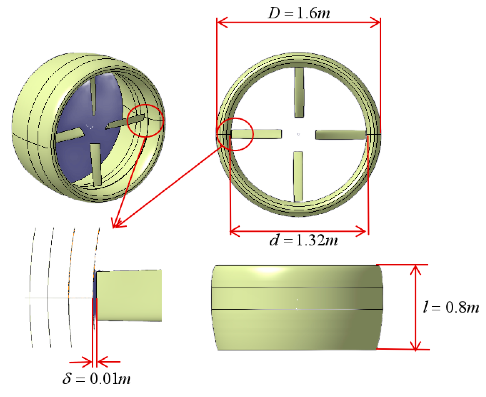
The aerodynamic performance calculation of the ducted fan is developed to validate the numerical method. The configuration we used in this paper is a ducted fan with four blades, as shown in
Figure 2. The propeller disk and the duct diameters are
and
, respectively, while the height of the system is
. The minimum gap distance between the rotor and the duct is
. The rotating speed of the propeller is
. We choose the
model [
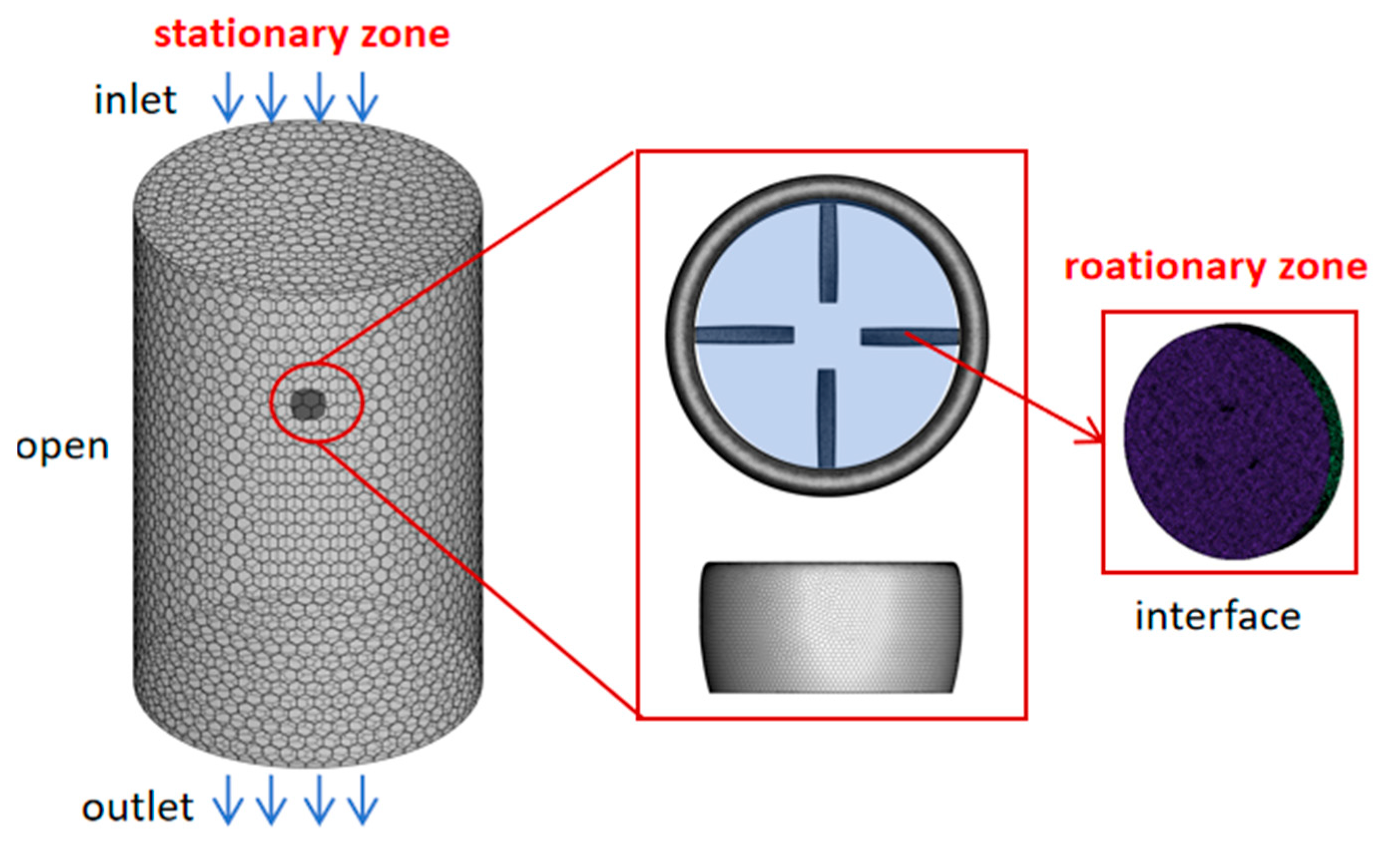
23] to evaluate the flow field of the ducted fan in level flight state. A dynamic sliding mesh is used to simulate the propeller rotation by dividing the whole flow field into static and dynamic parts, and an interface is created to connect the two parts. The static domain contains the outer duct. The dynamic domain is the zone between the interface and the inner duct. Because the inner part of the duct rotates with the entire rotation of the dynamic domain, a counter rotating speed is added to this wall to offset the rotation. The meshes near the leading and trailing edges of the duct and the blade are further refined to improve the calculation accuracy. The boundary conditions for the external stationary region include inlet, outlet, openings, and walls, while the rotating regions contain moving components and are set as wall boundaries. During the computation, the thrust and torque of the ducted propeller are monitored, with convergence criteria based on the relative change in these monitored quantities being less than 1 × 10
−4. The unstructured computational mesh generated with a total number of 3 million points in the internal motion area and a number of 6 million points in the external flow field area is shown in
Figure 3.
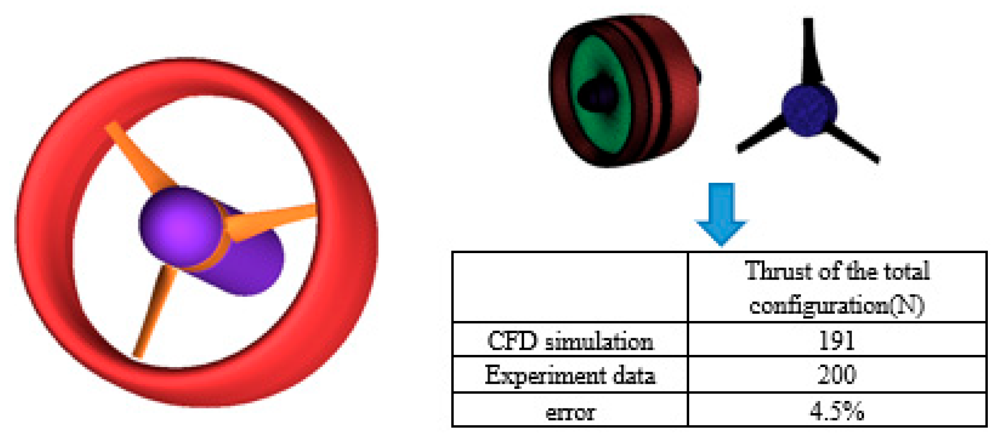
Before validating the ducted propeller in this study, a standard model propeller has been used to verify the computational method. This ducted propeller is a standard model developed by NASA in the 1960s for VTOL aircraft [
24]. Using the
model, simulations are conducted to analyze the aerodynamic forces under hover conditions, with results shown in
Figure 4. It can be observed that, based on this turbulence model, the aerodynamic characteristics of the ducted propeller configuration can be reasonably accurately obtained.
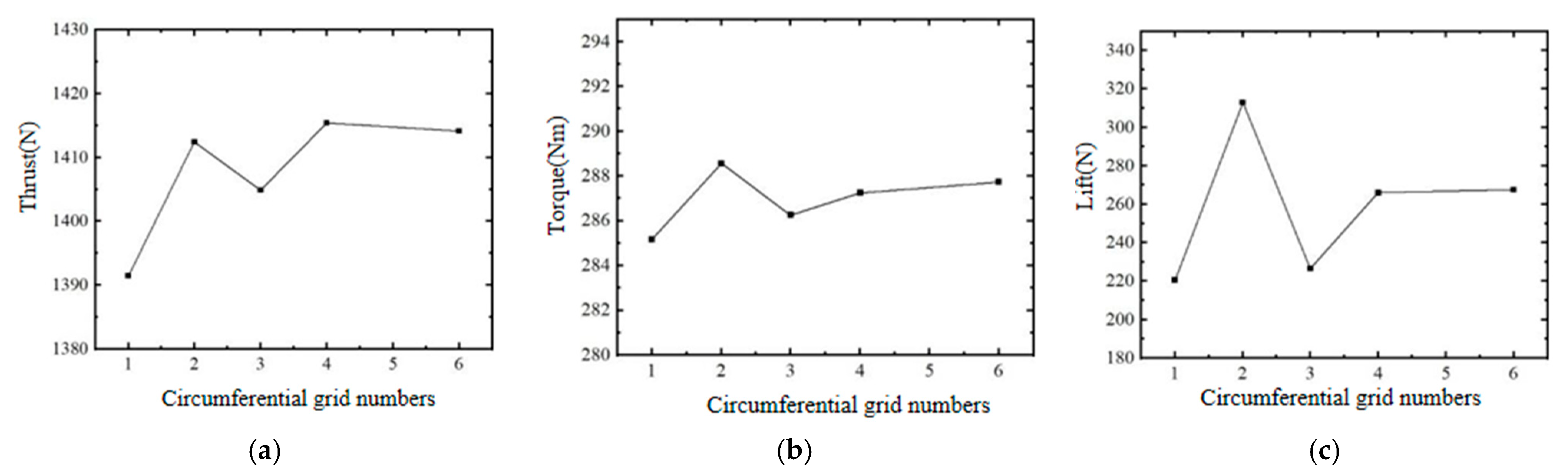
This article calculates the characteristics of a ducted fan at sea level with an incoming flow velocity of 50 m/s and a cruising flight angle of attack of . The simulation results show that the duct and propeller generate a total thrust of 1400 N, of which 540 N is generated by the duct and 860 N is generated by the propeller. The thrust of the duct accounts for 38%, fully demonstrating that the duct can improve the thrust characteristics of the entire system. Additionally, to validate the influence of grid quantity, this study modifies the node density in the wake region of the blades, the leading and trailing edges, as well as near the duct lip, forming computational grids with 6 million, 12 million, and 15 million points. Grid independence validation has been conducted using the same method, yielding total thrust values of 1380 N, 1406 N, and 1405 N, respectively. The deviations from the results obtained with a 9 million grid are 1.2%, 0.42%, and 0.36%. This indicates that the 9 million grid generated in this study is sufficient to relatively accurately describe the aerodynamic characteristics of the ducted propeller system. All subsequent simulations will adopt this grid partitioning strategy.
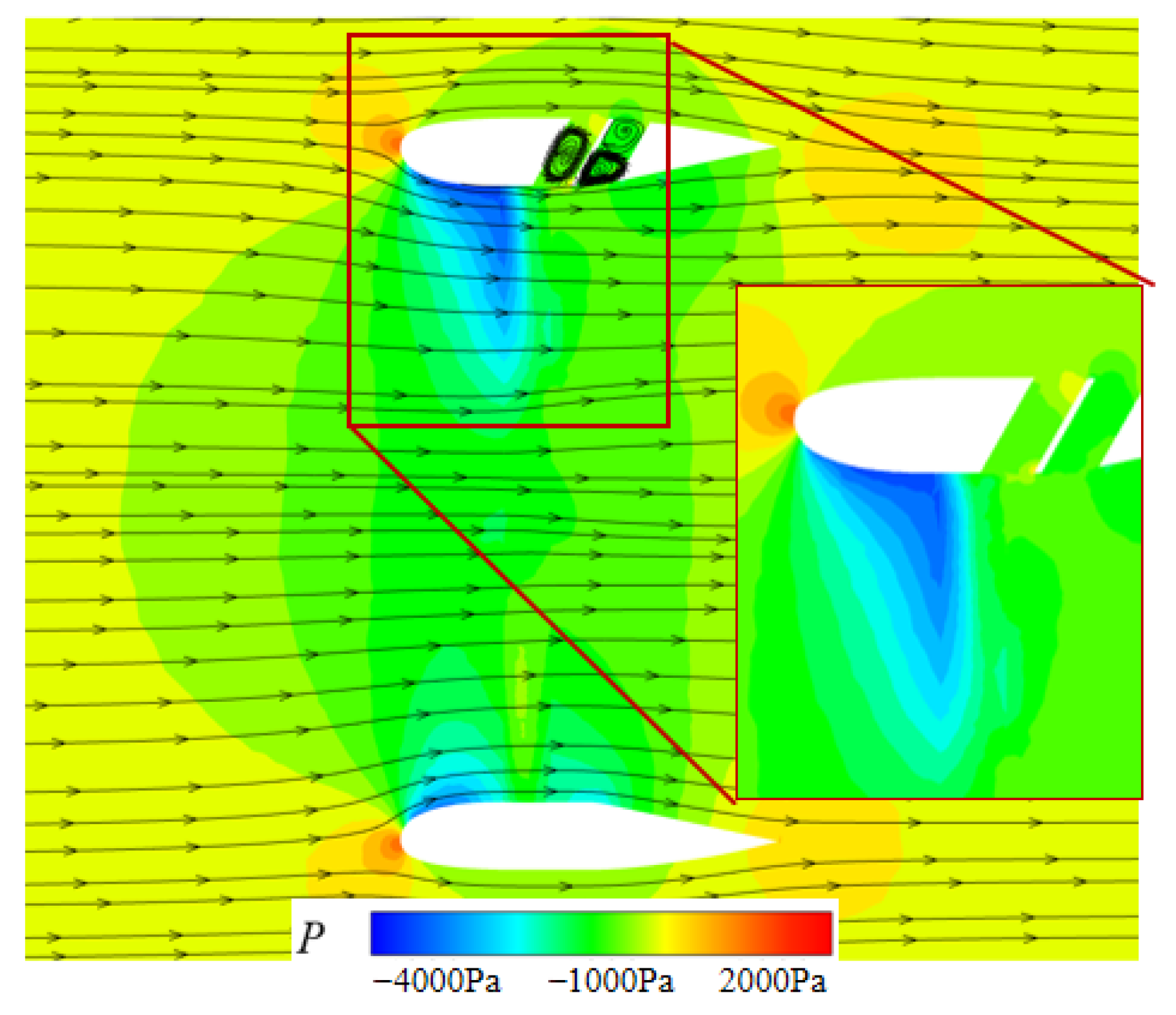
Figure 5 shows the basic flow characteristics of the propeller. From the simulation results, it can be seen that compared to conventional propellers, the enveloping effect of the duct improves the efficiency of the entire power system. The main reason why the duct can generate additional thrust is that the pressure drop caused by the propeller creates a significant suction effect inside the duct, which causes the external airflow to flow towards the inside of the duct. When passing through the leading edge of the curved lip of the duct, a distinct low-pressure suction area is created, thereby inducing the generation of an axial thrust component.
Therefore, from the aerodynamic characteristics of the ducted fan, in addition to generating pressure drop to stimulate the flow field inside the duct, propellers also induce the generation of ducted turbulence. As a result of the presence of ducts, the airflow leakage at the tip of the propeller is weakened, and the aerodynamic efficiency of the propeller itself is also improved.
3.2. Outline Design of the Duct-Grid Fusion Configuration
The simulation results of the aerodynamic characteristics of the duct show that the main source of thrusts generated by the duct is the suction area of the lip. The ducted fan attracts and accelerates the external airflow. After passing through the arc-shaped lip area, the airflow velocity in that area increases and the static pressure decreases, thereby forming additional thrust. However, the shape of the duct itself is an axisymmetric rotating body, which means that its lift surface characteristics have not been effectively utilized in cruising flight.
This article proposes an improved design for the local duct shape based on the unique characteristics of grid channels [
25,
26]. On the one hand, by embedding grids into the duct through asymmetric design, the axisymmetric characteristics of its shape or flow field can be broken, providing a basic environment for the formation of the lift zone on the duct surface; on the other hand, by utilizing the effect of multiple grid channels, the pressure difference inside and outside the duct is balanced, resulting in minimal mixing of internal and external airflow, thereby reducing interference with thrust effects, as shown in
Figure 6.
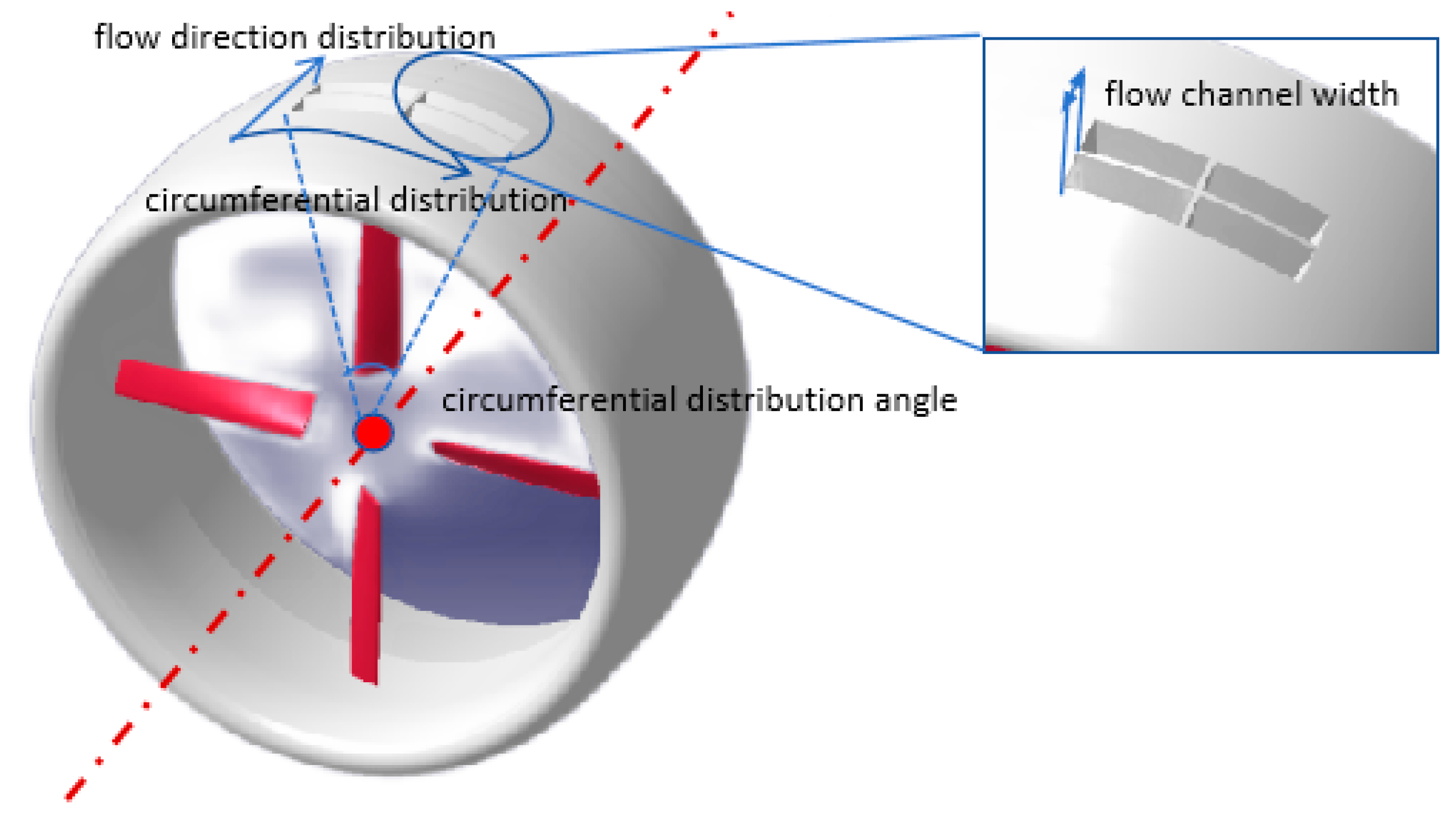
According to the flow characteristics of the duct section without grids, the lifting grid design is carried out as follows:
Step 1: Based on the concept of asymmetric geometry/aerodynamic design, the opening position is determined on the inner wall of the duct to form the conditions for generating lift on the duct wall;
Step 2: Determine the grid diversion angle;
Step 3: Determine the grid channel width;
Step 4: Design the grid channel shape based on the curvature of the guiding string as a measurement standard;
Step 5: Design the range of grid circumferential angles and the number of grids;
Step 6: Complete the design of grid duct fusion configuration.
It is inevitable that due to the asymmetric grid duct design scheme, lateral forces will be generated during vertical takeoff and landing, but they can be balanced by the deflection of the rudder surface on the bottom of the duct. Despite the cost of controlling the takeoff and landing phase, the cruise phase still occupies most of the entire flight envelope. Therefore, the exploration and utilization of the lift of the duct have significant benefits.
The basic external parameters of the initially designed grid channel are as follows: the distance from the front end to the duct lip is 0.36 m, the channel width is 0.07 m, the grid inclination angle is
, and the grid circumferential distribution angle is
. The number of grid distributions in the circumferential and flow directions of the initial configuration is both 2, forming a
distribution form as shown in
Figure 7. The parameters such as the inclination angle inside the culvert are not considered here. The main reason is that the grid channels here induce changes in the front flow field and balance the differences inside and outside the duct. Therefore, the internal structure has a relatively small impact on the overall design concept.
3.3. Aerodynamic Characteristics Analysis of Duct-Grid Fusion Configuration
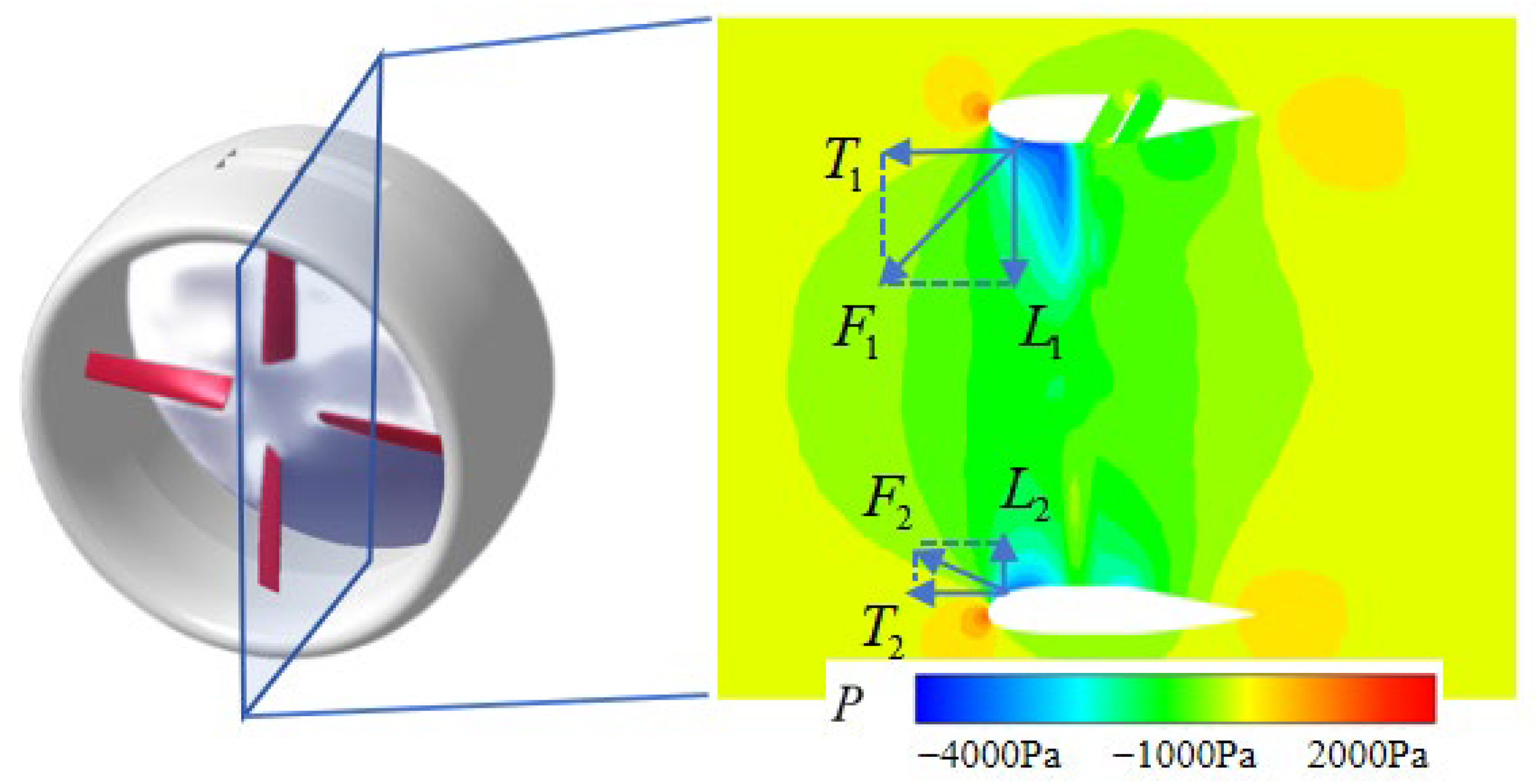
The aerodynamic characteristics of the duct-grid fusion configuration were analyzed using the same simulation method as the original duct fan, with the simulation conditions remaining consistent. The sliding grid technology was also adopted to simulate the motion phenomenon of the propeller relative to the duct. The comparison of the obtained aerodynamic results is shown in
Table 1. It can be seen that after embedding the grid in the duct, the thrust remains basically unchanged, reflecting that even if multiple sets of grid channels are embedded on the duct wall, there is no significant increase in resistance. The overall torque slightly increases since the main component contributing torque is the propeller. When the axial symmetry of the duct is broken by the grid channel, the local flow field of the propeller is disturbed, causing leakage resistance when the blade rotates through the grid channel mouth, resulting in a slight increase in torque and corresponding power. The results in
Table 1 also indicate that considerable lift is generated on the duct wall due to the embedding of grid channels. Taking the takeoff weight of the V-BAT at 57 kg as an example, if the power plant configuration described in this article is adopted, the 30 kg lift generated on it can share 52% of the total lift demand of the aircraft, which can unload the wing lift. With the same wing load, the wing area can be reduced by 52%. If a rectangular wing is used, the span can be reduced by half. This design concept brings great benefits, as it can be used in a narrower space or more drones of this type can be deployed in the same space.
Figure 8 and
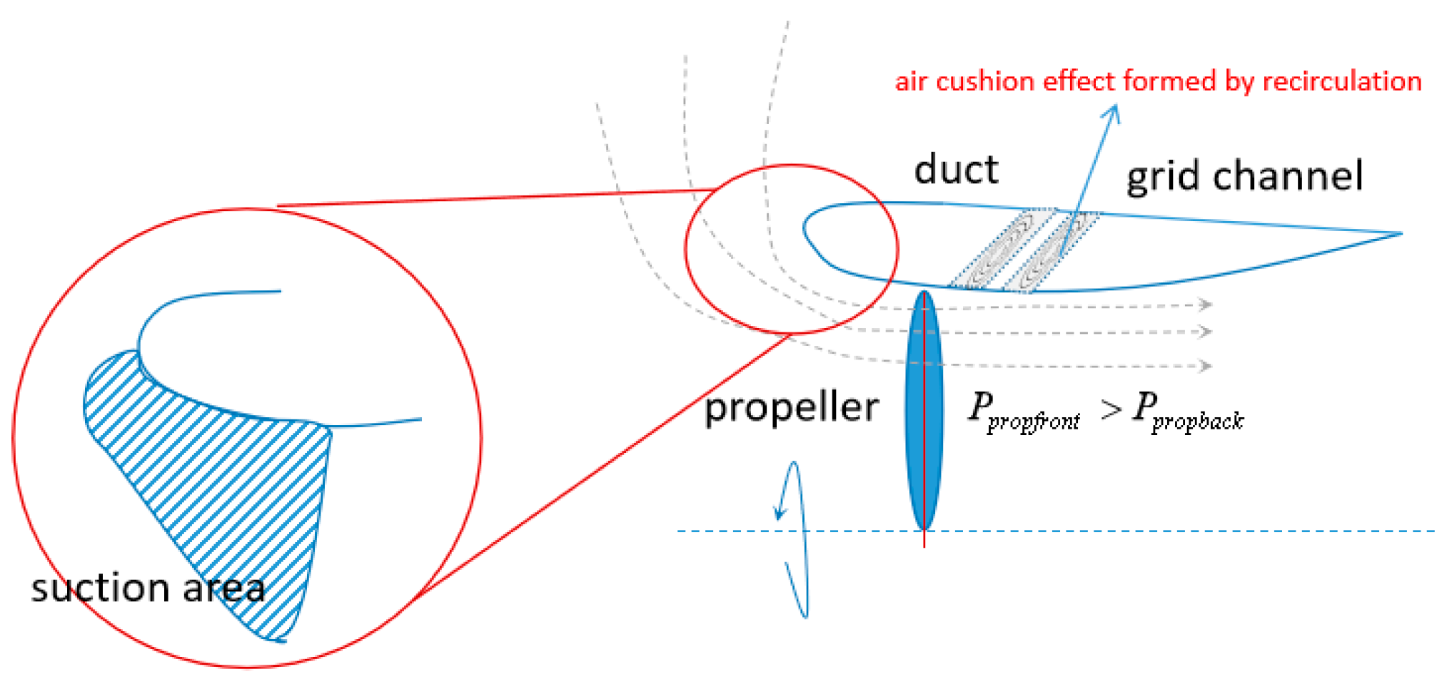
Figure 9 show the flow field information related to the duct-grid fusion configuration. From the cross-sectional streamline diagram, although grid channels are embedded on the duct wall, a local airflow stagnation zone is actually formed inside due to the small pressure difference between the inside and outside of the channel. The airflow inside the duct does not pass through the grid channels in large quantities and affect the outside of the duct. The advantage of this phenomenon is that the air inside the grid fills the channels, so that the internal and external streamlines are not heavily mixed, thus not having a significant impact on the thrust.
The greatest advantage of the existence of the grid channel is that it induces further expansion of the low-pressure area near the lip, resulting in an increase in the resultant force vector near the lip. However, the thrust component is equivalent to the thrust component on the side without the grid. The component in the lift direction is significantly increased compared to on the side without the grid. Therefore, the overall effect is that the total thrust remains almost unchanged, while the total lift increases significantly. In other words, after embedding the grid channel into the duct, the basic performance of the thrust direction of the culvert is maintained as much as possible, but it induces changes in the low-pressure area near the lip, resulting in a lift difference.
The main thrust of the ducted fan originates from the propeller momentum and the suction zone induced by the propeller at the duct lip. A smooth airflow transition from the lip to the duct expansion section ensures the additional thrust of the duct. As shown in
Figure 7, the design of a grid channel in the straight duct section creates a stable “reverse flow cushion” inside the flow field around the duct, which does not significantly interfere with the original flow direction or flow rate of the transitional airflow (
Figure 10), thus maintaining the basic thrust characteristics. However, due to the presence of the grid channel, it induces changes in the suction force difference on both sides of the duct, thereby generating additional lift. In other words, while the duct’s sealing is disrupted, the pressure difference before and after the propeller disk inside the duct, as well as the axial pressure difference between the duct lip and the expansion section, remain unaffected. This ensures that thrust characteristics are not disturbed while lift is generated.
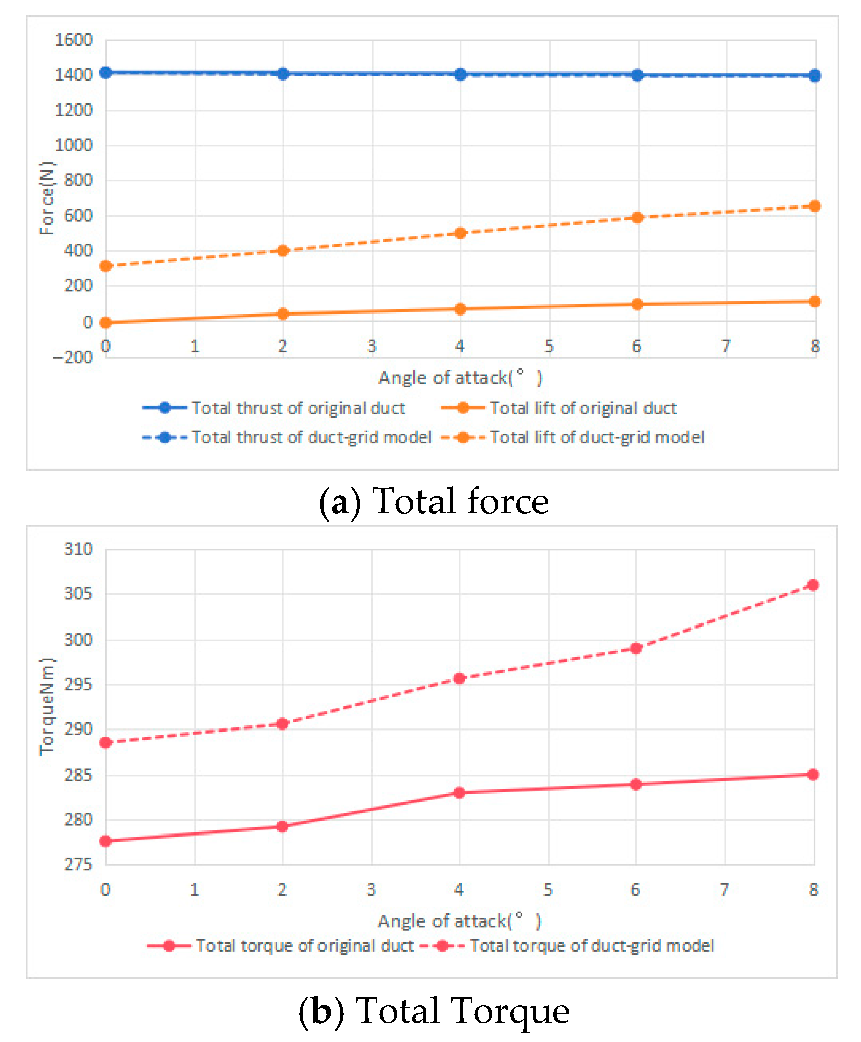
Figure 11 shows the aerodynamic performance curves of ducted propellers with and without grid channels at different angles of attack. As the angle of attack increases, even the duct without grids can generate some lift, while the grid channel in this study further amplifies this effect. However, it should also be noted that as the angle of attack increases, the torque of the duct with embedded grids gradually increases, even exceeding the case without grids. At this point, the grid channel begins to produce significant resistance. In other words, the grid channel configuration in this study is applicable within a certain range of angles of attack.
4. Analysis of the Influence of Fusion Configuration Design Parameters
Comparing the duct-grid fusion configuration with the conventional duct fan, in the forward flight state, the introduction of multi-channel grids increases the tendency of high-energy airflow inside the duct to flow outside, resulting in a more objective increase in lift on the grid channel surface. This section discusses the influence of grid design parameters on the overall lifting effect of the fusion configuration, including the range of circumferential distribution angles, the number of circumferential grids, the number of flow direction grids, and the grid width.
4.1. The Influence of Grid Circumferential Distribution Angle
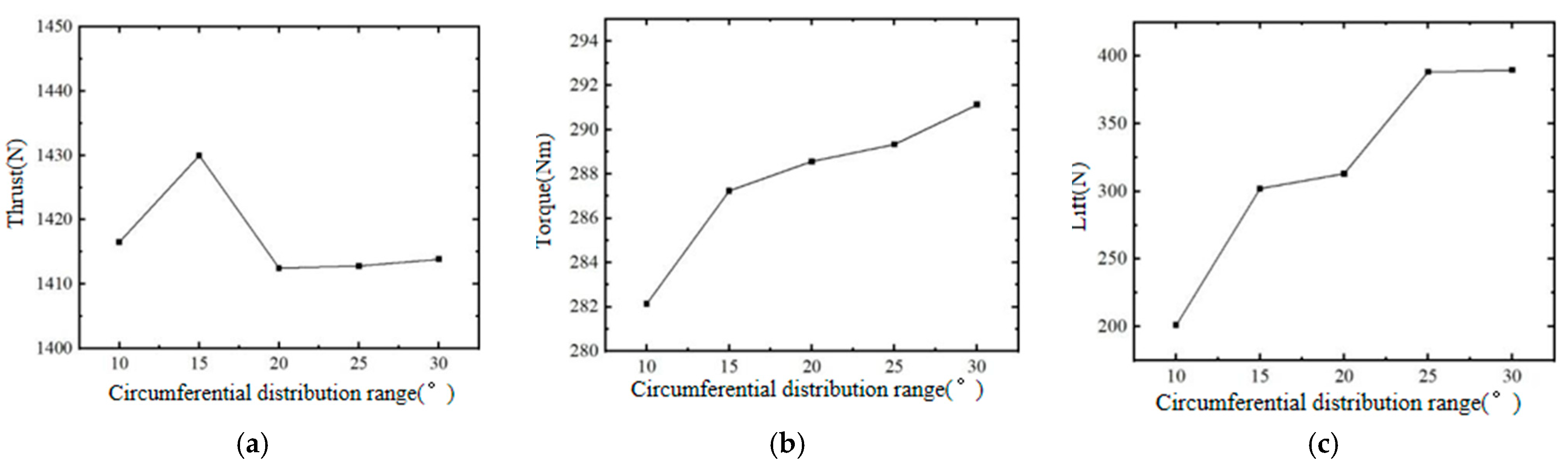
The circumferential distribution angle determines the circumferential embedding range of the grid on the duct, and this range is not necessarily the larger the better. According to the design principle of this article, the reason why the duct with embedded grid generates lift is due to the difference in force components between the duct with and without grids. If the circumferential distribution angle exceeds 180 degrees, this difference relationship may actually deteriorate. This paper analyzes the circumferential distribution angles between and , with a focus on the changes in aerodynamic characteristics of ducted propellers caused by angle variations.
Figure 12 shows the influence of the grid circumferential distribution range on the aerodynamic characteristics of the entire ducted propeller. The increase in the circumferential range of the grid has almost no effect on thrust, but both torque and lift increase with the expansion of the circumferential distribution range. This result indicates that embedding the grid into the duct wall does not significantly affect the thrust effect. However, due to the increased leakage range near the blade tip, the circumferential resistance of the blade increases, resulting in an increase in torque. Within a certain range, the increase in the distribution range of the circumferential grid leads to a further increase in the difference in force components between areas with and without grids, resulting in an increase in lift. From a distribution range of
to
, the lift has nearly doubled.
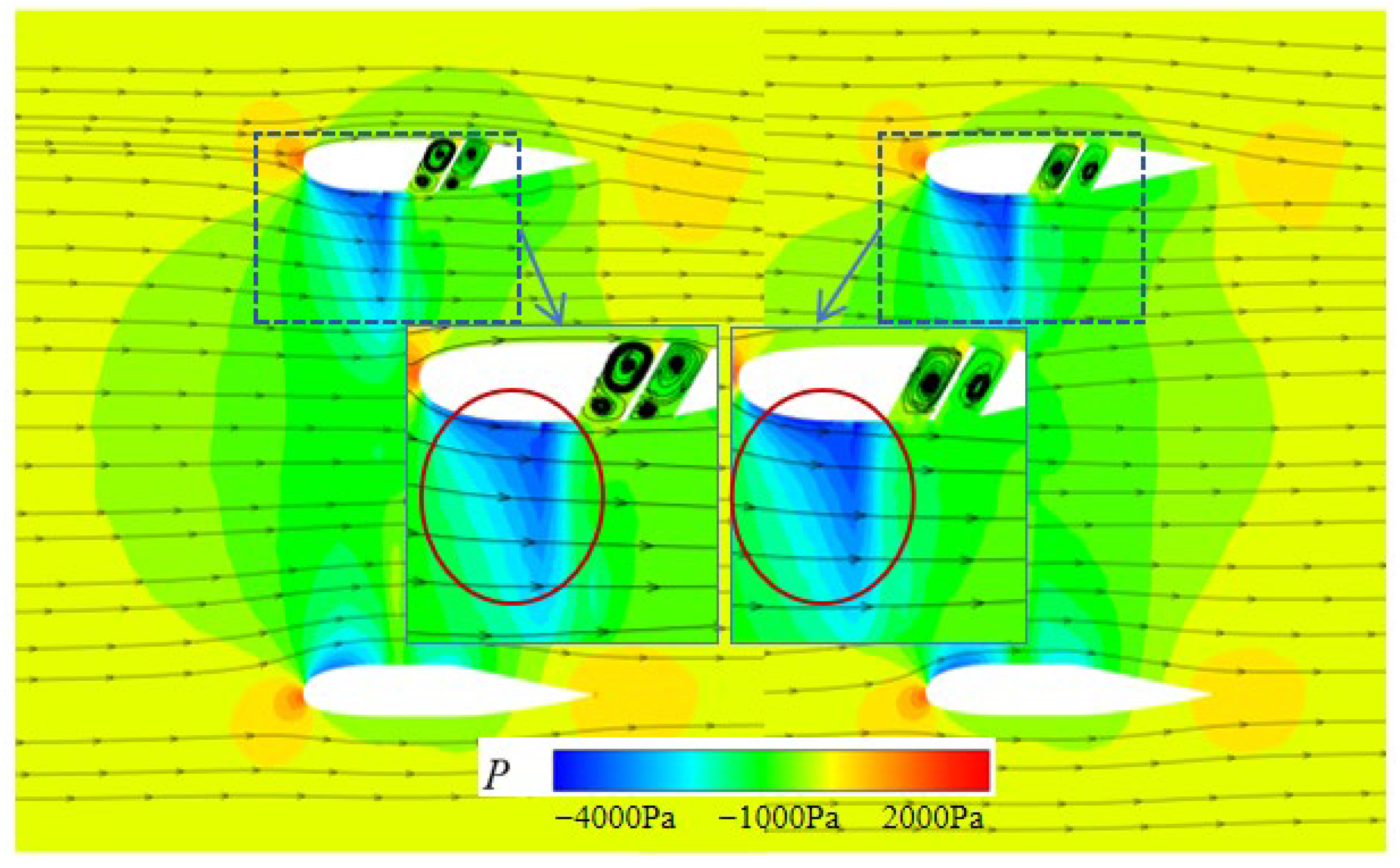
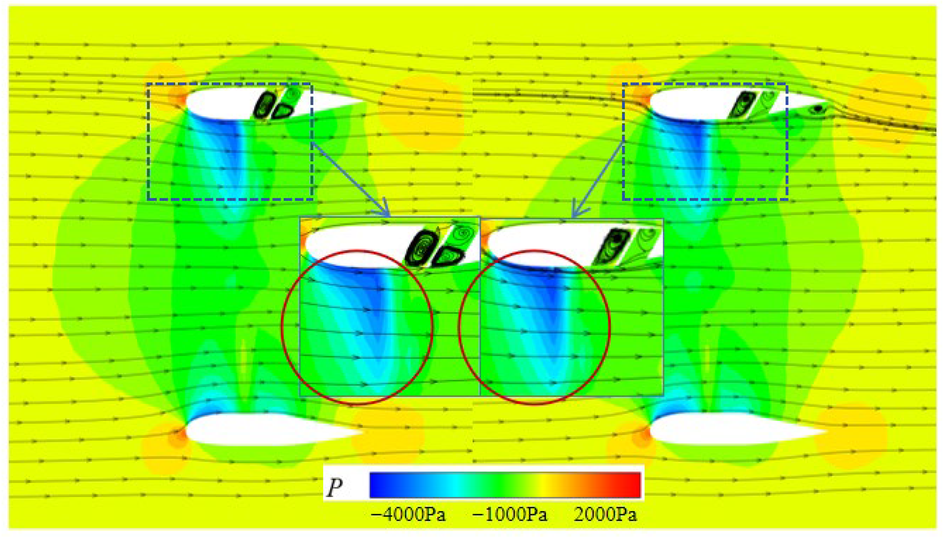
Figure 13 presents the cross-sectional cloud images of these two circumferential distribution angle ranges. It can be seen that when the circumferential distribution angle is
, the grid induces a slight expansion of the low-pressure area on the inner wall of the duct at the front end, and the pressure difference in the low-pressure area also increases significantly, further increasing the lift caused by the difference in the effective component.
4.2. The Influence of Grid Channel Width
The width of the grid channel represents the size of the “hysteresis zone” encountered during the propagation of airflow on the duct wall. From the perspective of the grid duct embedding design concept in this paper, because the pressure difference between the inner and outer walls of the duct is not significant, an airflow stagnation zone is formed inside the grid channel, which appears as a relatively stable separation vortex on the streamline.
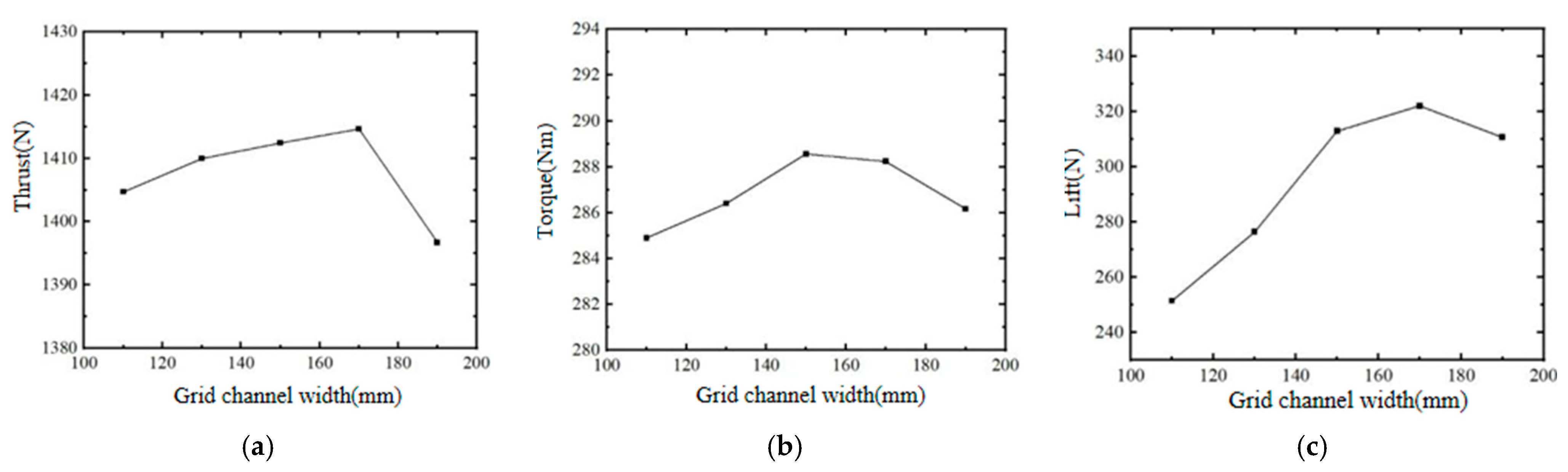
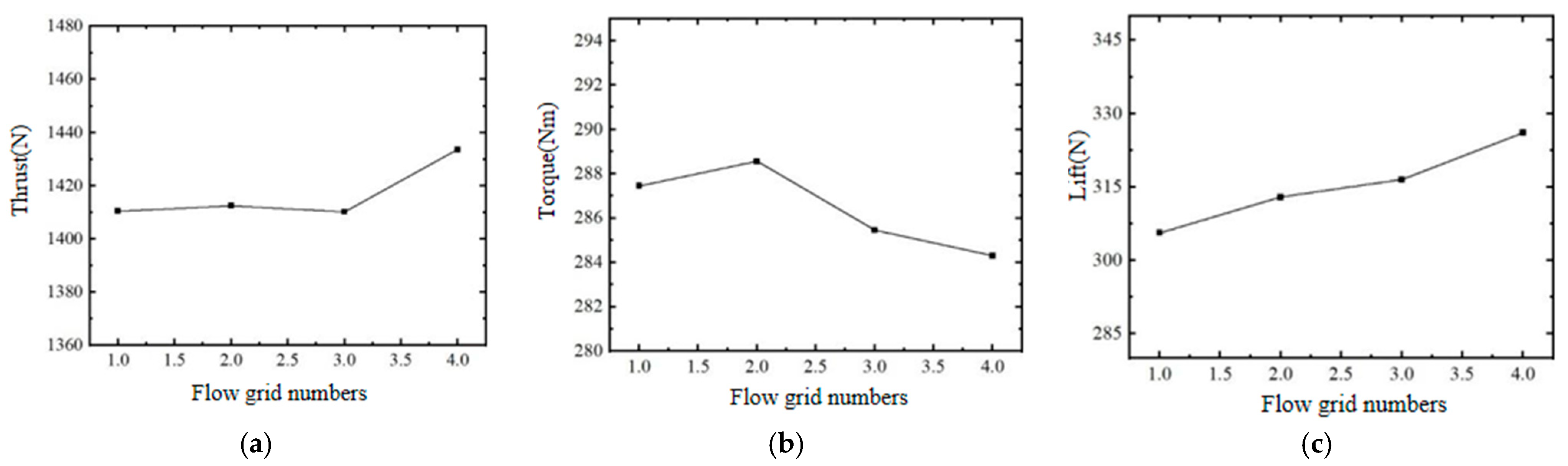
Figure 14 shows that as the width of the grid channel increases, thrust, torque, and lift all increase and then decrease, reflecting that when the grid channel is too wide, drag is generated in the cruising flight direction, and the difference in force components is also affected by the presence or absence of grids.
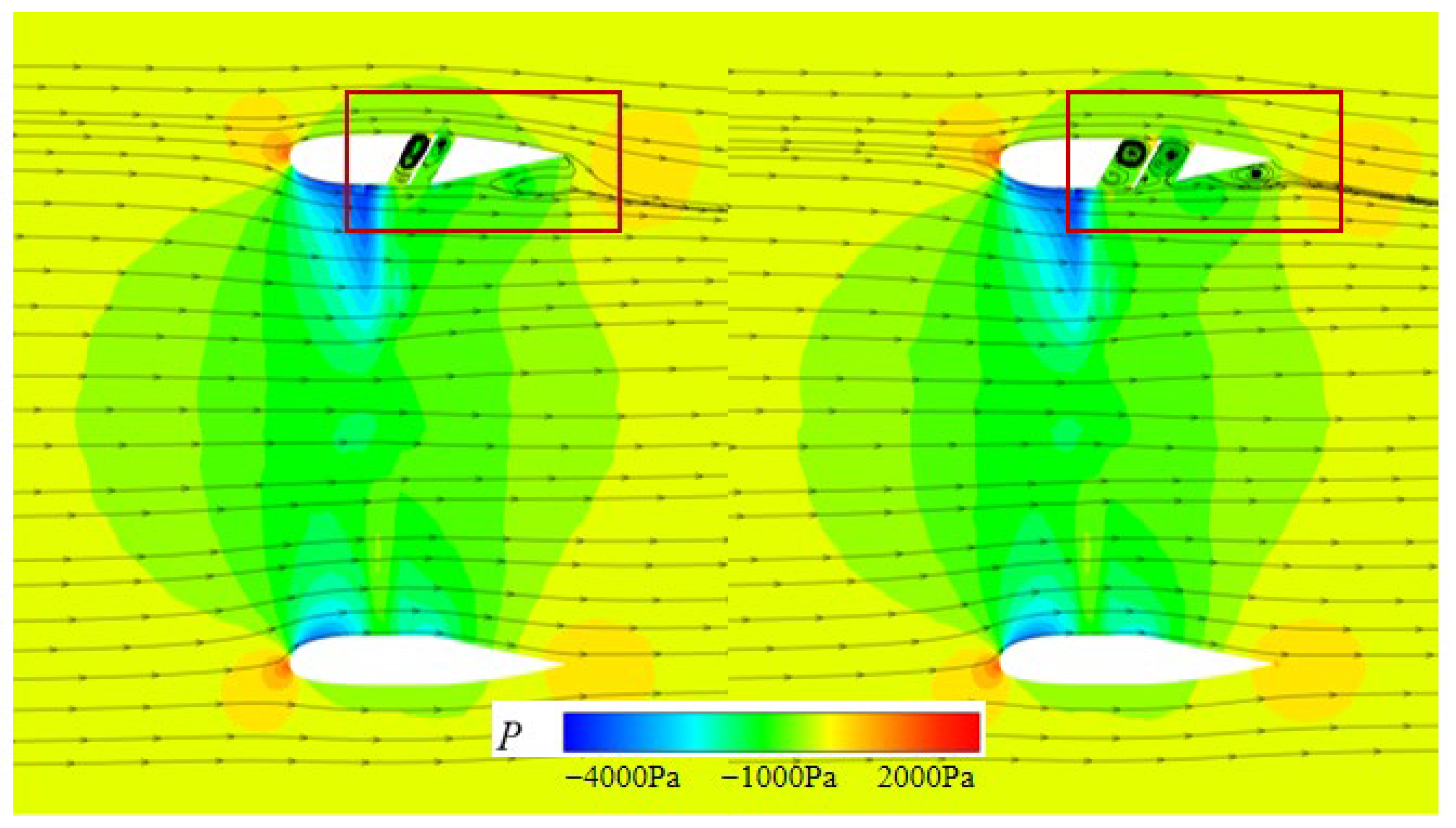
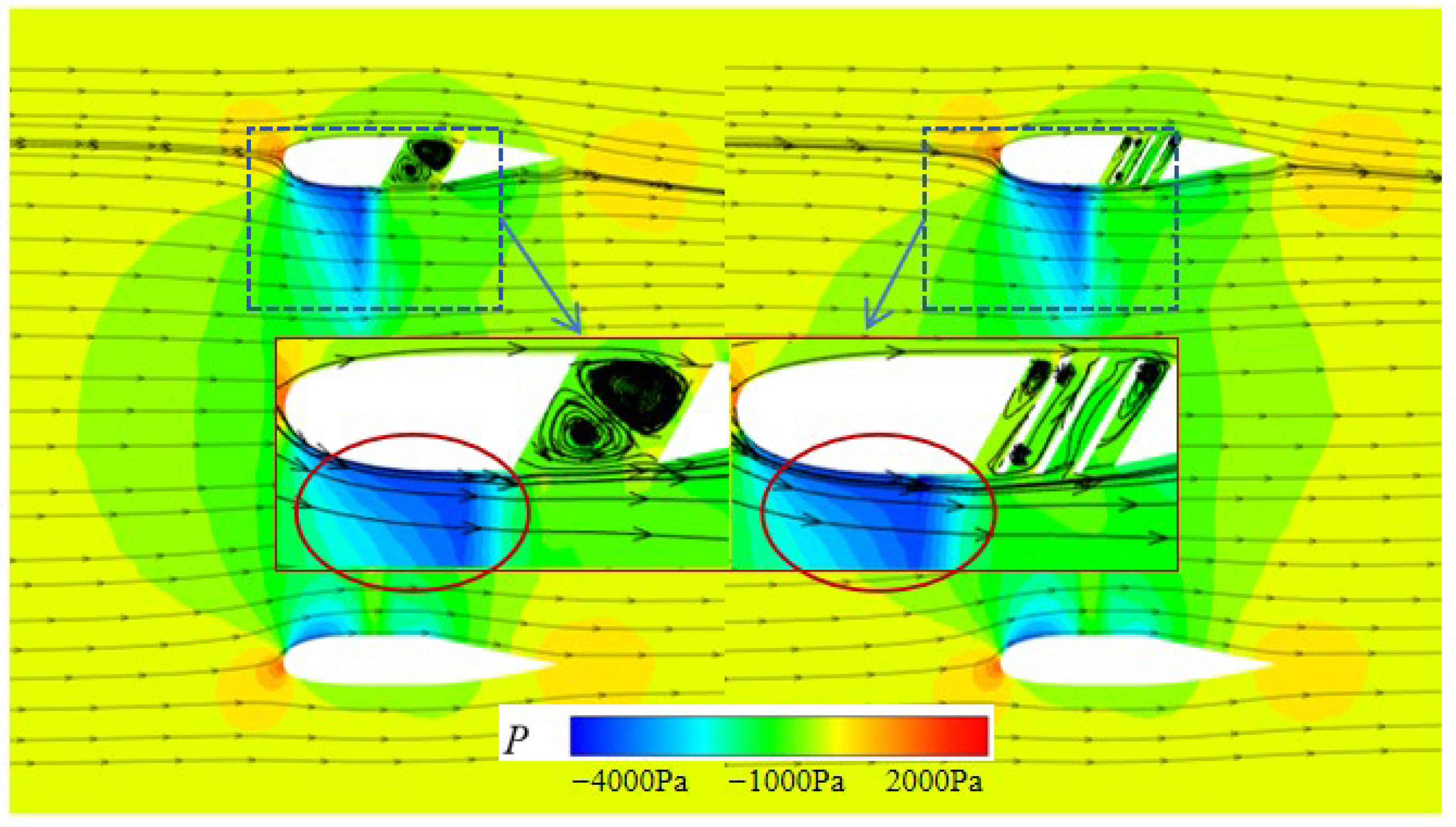
The cross-sectional flow fields at grid channel widths of 110 mm and 190 mm are shown in
Figure 15. It can be clearly seen that due to the increase in channel width, although a relatively stable separation vortex is still maintained inside, it has actually disturbed the flow near the inner wall of the duct, causing a separation flow at the rear of the duct. As the width of the channel increases, this separation effect also increases, resulting in an increase in channel resistance and a decrease in static thrust. At the same time, as the width of the culvert channel increases, it also weakens the low-pressure area in the front, resulting in a slight decrease in the lift generated by the duct-grid fusion configuration. The simulation results indicate that the width of the channel should not be too large, and an appropriate width should be able to induce a significant front low-pressure zone, but should not cause significant disturbance to the airflow inside and outside the duct.
4.3. The Influence of the Number of Circumferential Grids
Due to the axisymmetric layout of the duct, the internal airflow also exhibits a uniform circumferential distribution. When embedding grid channels on the wall, the number of circumferential grid cells affects the size of the air flow stagnation zone cells within the same circumferential distribution range.
Figure 16 shows the effect of different numbers of circumferential grids on the aerodynamic characteristics of ducted propellers.
It can be seen that as the circumferential distribution of the grid cells becomes denser and denser, the thrust slightly increases and then remains basically unchanged, while the torque changes remain basically stable. The increase in the number of grids actually exerts a certain constraint on the leakage effect of the blade tip, thus benefiting the torque and power characteristics. For generating additional lift, the number of grid circumferential cells is not necessarily the more the better, and there exists a relatively optimal value for the number of cells.
Figure 17 shows the cross-sectional streamlines and pressure distribution cloud images when the circumferential
flow direction values are
and
, respectively. As the number of circumferential units increases, both the low-pressure zone on the inner wall of the duct induced by the grid and the separation phenomenon at the rear of the duct are basically similar. This indicates that the number of circumferential grids has a relatively small impact on the aerodynamic forces of this composite configuration.
4.4. The Impact of the Number of Flow Grids
When keeping the coverage range and number of cells of the circumferential grid unchanged, changing the flow direction of the grid cells actually divides the width of the grid channels, and the aerodynamic results obtained are shown in
Figure 18. As the number of flow grid cells increases, the thrust increases while the torque decreases, resulting in an increase in additional lift. It can be seen that the number of flow elements has a more significant impact on the entire composite configuration compared to the number of circumferential grid elements.
After the increase in flow grid cells, the separated vortices in the original hysteresis region are divided into multiple small separated flows, which further expands the low-pressure area in the front and improves the flow field quality in the rear of the duct, as shown in
Figure 19. When the combination form of the circumferential
flow direction combination form is
, a small separation area appears at the rear of the duct. However, when the combination form is
, this separation phenomenon is improved. In addition, due to the increased flow density of the grid, the constraint on the blade tip airflow is strengthened, significantly improving the additional resistance generated, resulting in a decrease in torque.
It should be noted that, in this study, the range of parameter variations selected during the grid parameter influence analysis is relatively small. This is related to the lift generation mechanism of the duct-grid composite configuration. The grid angle is fixed at 60° to create a stable “vortex cushion” within the grid channel. If the angle is too large, unstable separated flow occurs inside, leading to additional drag. Conversely, if the angle is too small, internal flow leakage occurs, weakening the lift effect and affecting the number of grids in the flow direction, which has similar considerations. The circumferential angle and the number of circumferential grids are determined based on the relative range of the ducted and grid sections. Excessive circumferential distribution reduces the lift effect and causes uneven loading on the duct due to slotting, which may compromise structural safety.


