Article

Development and Experimental Study of a Seamless Morphing Trailing Edge Flap Equipped with an Elephant Trunk Actuation Mechanism

by
Mir Hossein Negahban
,
Tarek Saci
and
Ruxandra Mihaela Botez
*
LARCASE Laboratory of Applied Research in Active Controls, Avionics and Aeroservoelasticity, École de Technologie Supérieure, Université du Québec, Montreal, QC H3C 1K3, Canada
*
Author to whom correspondence should be addressed.
Appl. Sci. 2025, 15(10), 5570; https://doi.org/10.3390/app15105570
Submission received: 6 April 2025 / Revised: 30 April 2025 / Accepted: 13 May 2025 / Published: 16 May 2025
(This article belongs to the Special Issue Multidisciplinary Collaborative Design of Aircraft)

Abstract

:
Following the promising performance of the seamless morphing trailing edge (SMTE) flap and its internal actuation system, the elephant trunk mechanism (ETM), investigated through aerodynamic and structural analyses, this study presents an experimental analysis of the SMTE flap equipped with an elephant trunk actuation mechanism. The morphing wing model was prototyped using a 3D printer. Four elephant trunk morphing ribs were embedded inside the flap section, all covered with a flexible skin. The control system for flap actuation was installed in the wing box corresponding to four elephant trunk mechanisms using an appropriate graphical interface to control the SMTE flap deflections. The completed model was further tested in a subsonic wind tunnel to validate the numerical aerodynamic results, as well as the functionality of the elephant trunk mechanism in real conditions. The results confirm the reliability and practicability of the proposed elephant trunk mechanism for actuation, and a very good agreement was obtained between the numerical aerodynamic data and wind tunnel test results.

1. Introduction

Introducing a novel technology in Engineering, especially in the Aeronautics Industry, requires a comprehensive study of all related disciplines in an interchangeable manner to allow their real-life applications. Given this fact, morphing wing technology [1,2], a novel wing technology designed for next-generation aircraft, has been the subject of meticulous studies over the past few decades. It has been evaluated through several disciplines, including aerodynamic design [2,3,4,5], structural analysis [6,7], flight dynamics [8,9,10], actuation systems [11,12,13,14] and control [15,16,17]. The development of a morphing wing requires the contribution and integration of multiple disciplines. The promising advantages obtained from aerodynamic and structural studies in recent decades have encouraged further exploration of the practical application of morphing wings in the future. Considering the challenges concerning the practical applications of morphing wings [18,19,20], comprehensive research covering all disciplines involved is needed. These studies include investigating the reliability of morphing wings in real flight, their manufacturing possibilities and their maintenance cost. A limited number of morphing wing technology applications in real flight have been tested in recent decades: a joint project between Flexsys and the US Air Force Research Laboratory [21]; the CRIAQ MDO-505, a Canadian–Italian collaborative project [22]; the CRIAQ 7.1, a Canadian collaborative project [23], SARISTU [24] and Clean Sky 2 [25] in Europe are just a few. Several studies conducted by testing different types of morphing wings in wind tunnels can be found in the literature.

1.1. Literature Review

Recent advancements in morphing wing technologies have demonstrated significant potential for improving aerodynamic efficiency, flight control and operational flexibility. A notable example is the Adaptive Compliant Trailing Edge (ACTE) project, a collaboration between the US Air Force Research Laboratory (AFRL), NASA and FlexSys Inc [26]. Using a Gulfstream GIII business jet equipped with variable-geometry multifunctional control surfaces, the project successfully validated the FlexFoil material at 40,000 feet and Mach 0.75, eliminating wing–body discontinuities through seamless transition sections.
Efforts to design morphing leading edges have also gained considerable attention. Wang et al. [27] performed an experimental study by focusing on a morphing leading edge concept. They developed a two-step design process, including the optimization of a variable-thickness composite compliant skin and an inner kinematic mechanism. The skin was optimized using a laminate continuity model with constraints and employed a genetic algorithm to handle discrete and continuous variables. The kinematic mechanism optimization involved a coupled four-bar linkage system, designed to achieve optimal aerodynamic airfoils. The experimental results validated the feasibility of this approach, confirming its effectiveness in achieving the desired morphing functionality.
Similarly, Communier et al. [28] presented the design and wind tunnel testing of a morphing leading edge (MLE) system for a medium-range unmanned aerial vehicle. The MLE prototype, made with a simple wooden construction, successfully modified the stall angle without affecting the slope of the lift coefficient versus the angle of attack. However, the servomotor required significantly more power compared to a traditional LE flap.
Beyond leading edge morphing, several studies have concentrated on trailing edge morphing concepts. Jia et al. [29] presented the development and testing of a novel compliant morphing wing with a load-bearing morphing trailing edge. Optimized using a multi-disciplinary approach, the wing demonstrated stall mitigation, with a 1° delay in stall angle and a 13% increase in post-stall lift. The maximum deflection reached 37.9°, and the wing showed strong load-bearing capability. Experimental and numerical results were in good agreement, although the wing’s deformation was limited in the spanwise direction.
The integration of both leading and trailing edge morphing mechanisms has also been investigated for larger aircraft applications. Ricci et al. [30] described the experimental validation of a framework for designing morphing wings using in-house tools. This framework was applied to the design of morphing leading and trailing edges for a regional aircraft. A dedicated wind tunnel test campaign was conducted to validate the morphing devices, focusing on two phases: assessing the morphing shape and evaluating the aerodynamic performance. The results showed good accuracy between the predicted and measured morphing shapes, demonstrating the effectiveness of topology optimization methods, while the aerodynamic tests confirmed the potential benefits of the morphing surfaces and validated the design process.
Ameduri et al. [31] extended these efforts by focusing on manufacturing strategies for compliant structures for a morphing wing with leading and trailing edges. Their study involved the development of a reduced-scale wind tunnel model to validate the proposed morphing concept and to correlate numerical models, emphasizing the importance of material selection and fabrication techniques in achieving successful experimental validations at a small scale. This study outlined the design, manufacturing and wind tunnel test phases, highlighting the functionality of the morphing surfaces and the successful demonstration of the proposed concept in experimental wind tunnel conditions.
Several researchers have also explored combining multiple morphing strategies. Jeong and Bae [32] investigated a morphing wing by combining variable span morphing and variable camber variable chord morphing mechanisms. Their study included wind tunnel and flight tests to evaluate the aerodynamic changes and operational stability of the morphing mechanisms. The results confirmed increased lift coefficients and lift-to-drag ratios for the morphing mechanisms, especially when the morphing mechanisms were combined. However, challenges such as surface deformations of the latex skin during tests were noted, highlighting the need for further material optimization.
Investigations into local morphing applications, such as morphing ailerons, have further highlighted the potential for aerodynamic gains. Botez et al. [33] designed, manufactured and tested a wing-tip model featuring a morphing upper surface and interchangeable ailerons. The experimental results demonstrated that the morphing aileron extended the laminar flow over the wing surface by up to 9% of the chord length and achieved a drag coefficient reduction of up to 9%. These findings underscored the potential of morphing technologies to enhance aerodynamic efficiency by promoting laminar flow and reducing drag.
In addition to structural innovations, bio-inspired approaches have also emerged. Groves-Raines et al. [34] explored the benefits of combining two bio-inspired technologies: wing morphing and distributed pressure sensing. A wind tunnel model was developed with an avian-inspired wing capable of sweep motion, and pressure sensors were distributed across the wing surface. The results showed that the wing sweep could be an effective method for pitch control, enhancing the aircraft’s control authority at high angles of attack. Additionally, the pressure sensing system effectively detected the onset of aerodynamic stall, which could be used to implement an early warning stall system.
Finally, recognizing the broader environmental and economic benefits of morphing technologies, Salinas et al. [35] developed a validation methodology for the morphing wing, aiming to enhance fuel efficiency and reduce environmental impact. They conducted aerodynamic simulations and wind tunnel testing to assess the wing’s morphing capabilities and optimize the wing aerodynamic efficiency. The validation results confirmed that the morphing wing design performed as expected, with the experimental data. These findings validated the effectiveness of the morphing wing in achieving higher aerodynamic performance and lower fuel consumption.

1.2. Problem Definition

This work presents the final phase of morphing wing development, building upon our aerodynamic analysis of the SMTE flap [36], and structural evaluation of the proposed elephant trunk mechanism [37]. Previous studies assessed the aerodynamic performance of the SMTE flap, followed by a structural analysis of the elephant trunk mechanism and flexible skin. With these results in hand, the present study aims to develop a prototype of the UAS-S45 wing, equipped with both the SMTE flap and the ETM to experimentally validate the previous results. To achieve this, a section of the UAS-S45 wing was prototyped. This section integrated the elephant trunk mechanism, flexible skin and actuation control system within the wing box. The final model consisted of main components, including wing box, four elephant trunks, four actuation motors and the flexible skin. Figure 1 and Figure 2 illustrate the UAS-S45 wing equipped with an SMTE flap and the ETM actuation mechanism inside the SMTE flap, respectively.
Figure 1 shows the SMTE flap after morphing. Since there are no discontinuities between the flap and the wing body, the flap was seamlessly integrated with the wing body. Figure 2 illustrates the internal wing structure in detail. As shown in Figure 2, four ETMs were incorporated inside the SMTE flap, oriented as specified above. Previous studies have conducted both aerodynamic and structural analyses of the SMTE flap and the ETM actuation mechanism (see [36,37] for more detail).
This study underscores the critical role of precise manufacturing processes and advanced structural innovations in the development of functional and scalable morphing wing systems. By incorporating detailed manufacturing processes into the development of morphing wing systems, this study highlights the critical role that precision in fabrication plays. The integration of manufacturing considerations not only enhances the structural integrity but also ensures that the morphing wing system is ready for real-world application.
In the present study, a section of the UAS-S45 wing was prototyped for its testing in a wind tunnel. The wing section was designed to conform to the dimensions of the wind tunnel. This prototype included the SMTE flap, the ETMs inside the flap, a flexible skin and an actuation system embedded within the wing box. Figure 3 displays the fully assembled wing section, showcasing all its components.
The assembled prototype underwent several tests in the LARCASE Price–Païdoussis subsonic wind tunnel. During the tests, the real-time actuation of the wing was evaluated at various angles of attack and flap deflections. These tests allowed a performance assessment of the actuation system under operational conditions and facilitated the validation of the experimental data with the numerical aerodynamic results obtained in previous studies.

2. Design of Experiment (DOE)

This section presents the comprehensive development process of the UAS-S45 wing section, highlighting not only its structural and aerodynamic design but also the integration of advanced prototyping and actuation technologies. Given that the objective of this study is the development of a seamless morphing trailing edge (SMTE) flap system, the manufacturing strategy, in particular the use of additive manufacturing, plays a critical role in achieving the desired functional performance in the wind tunnel tests.

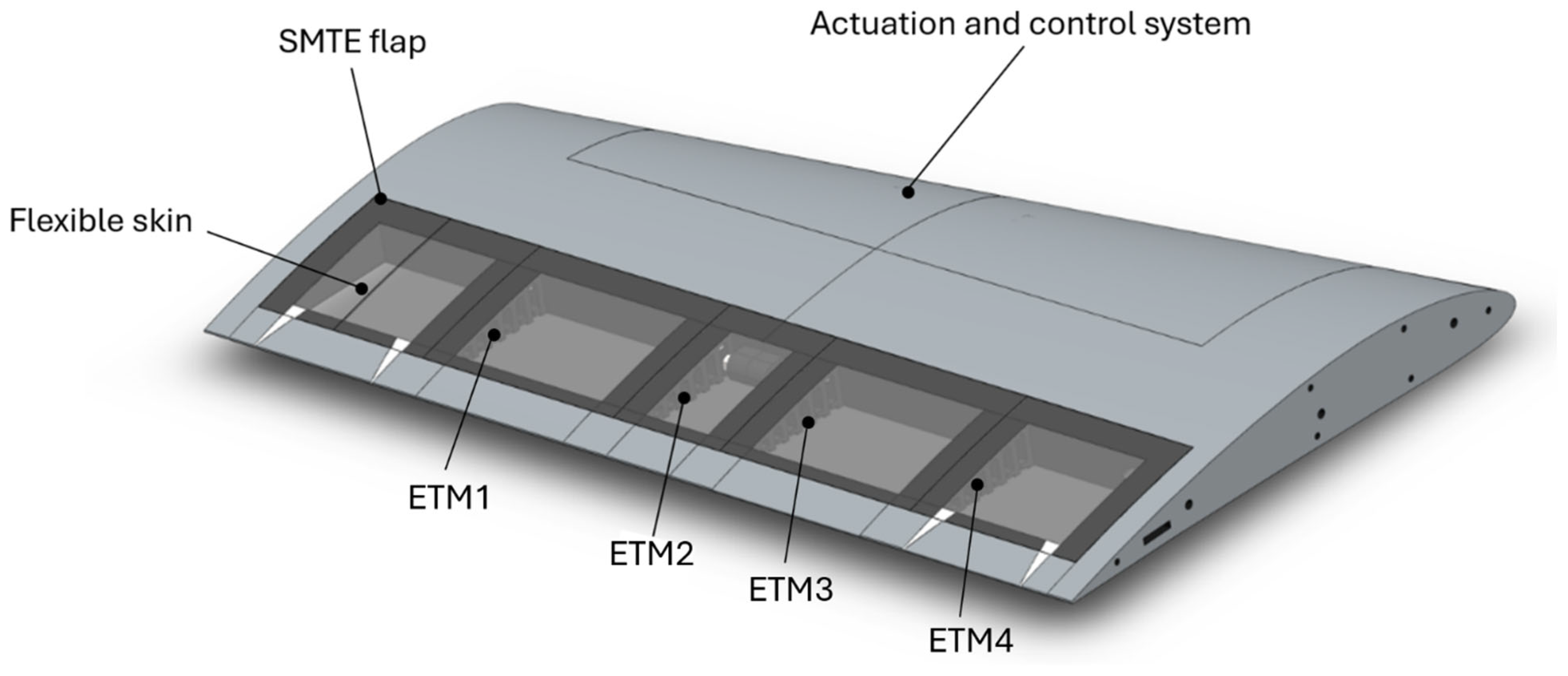
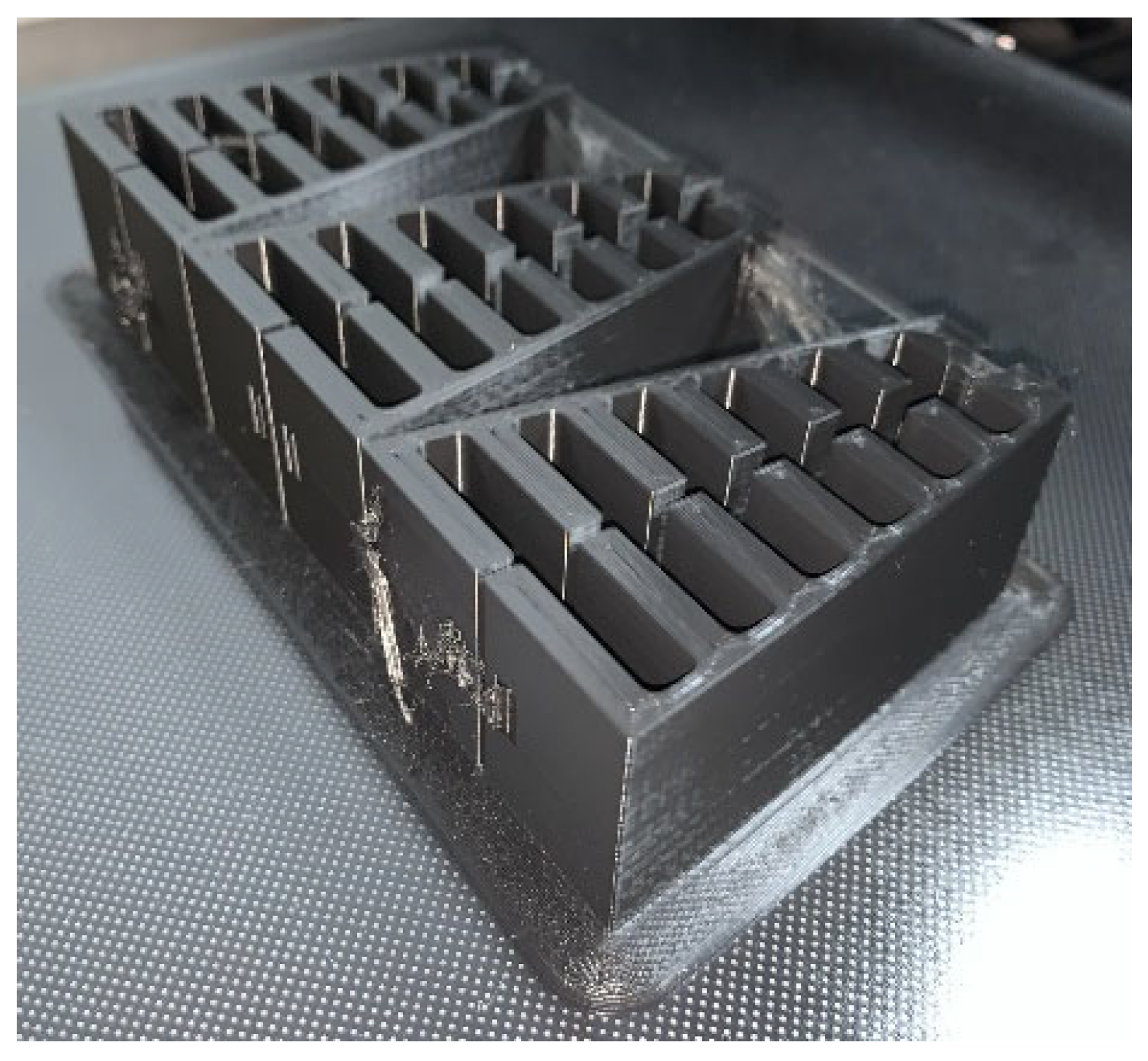
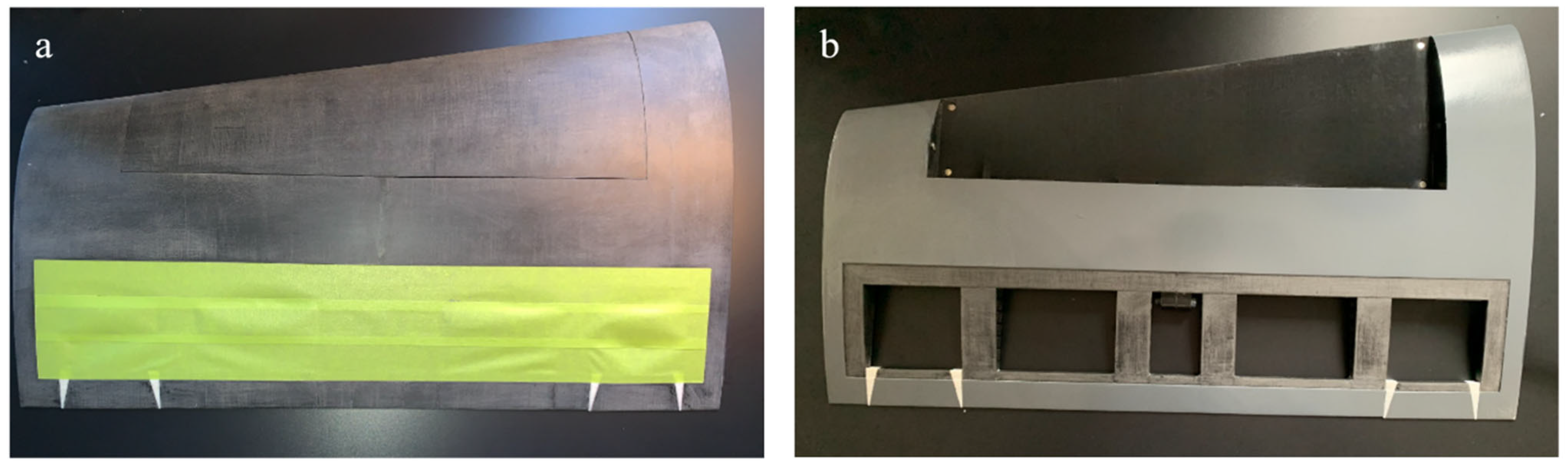
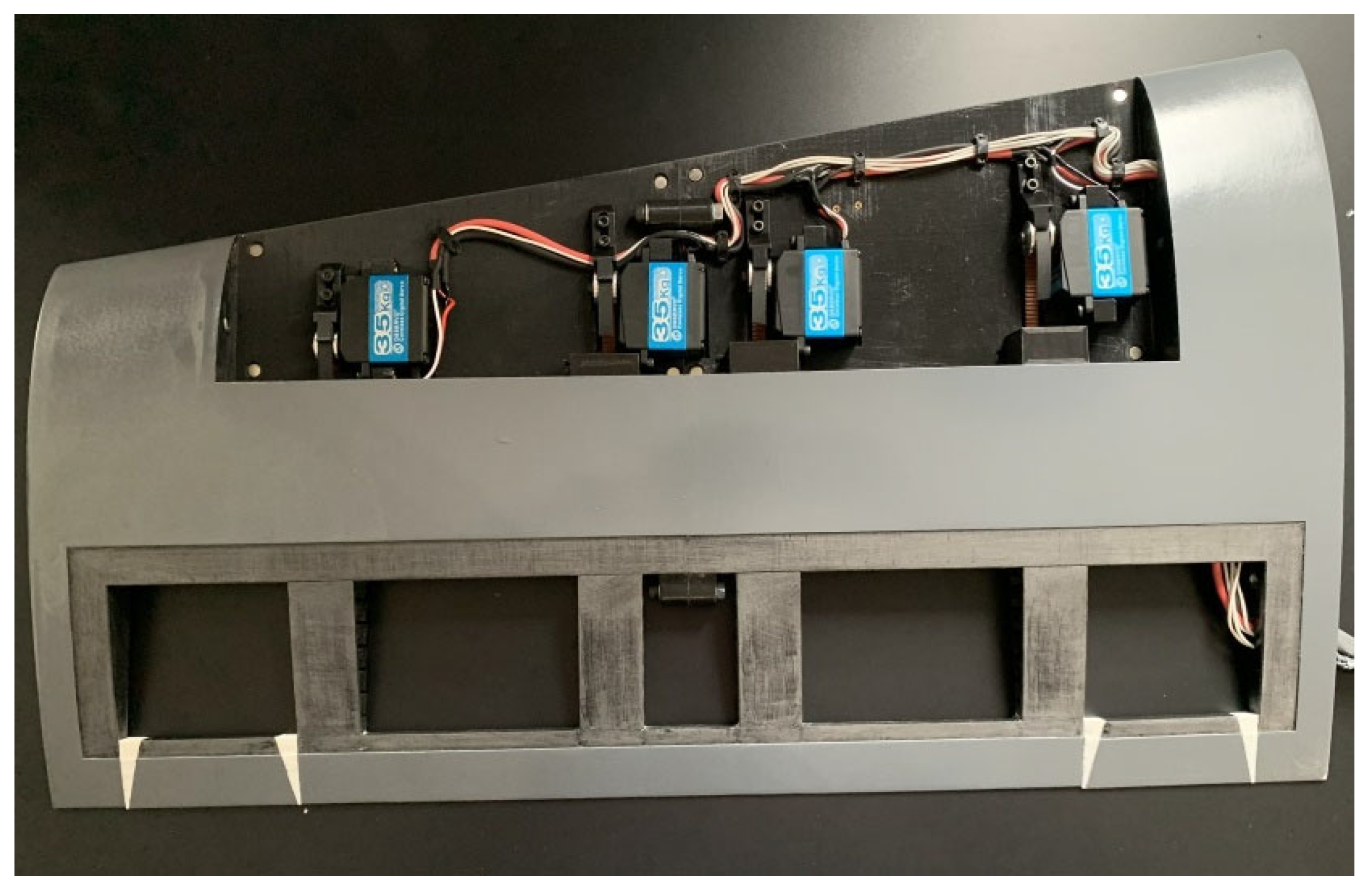
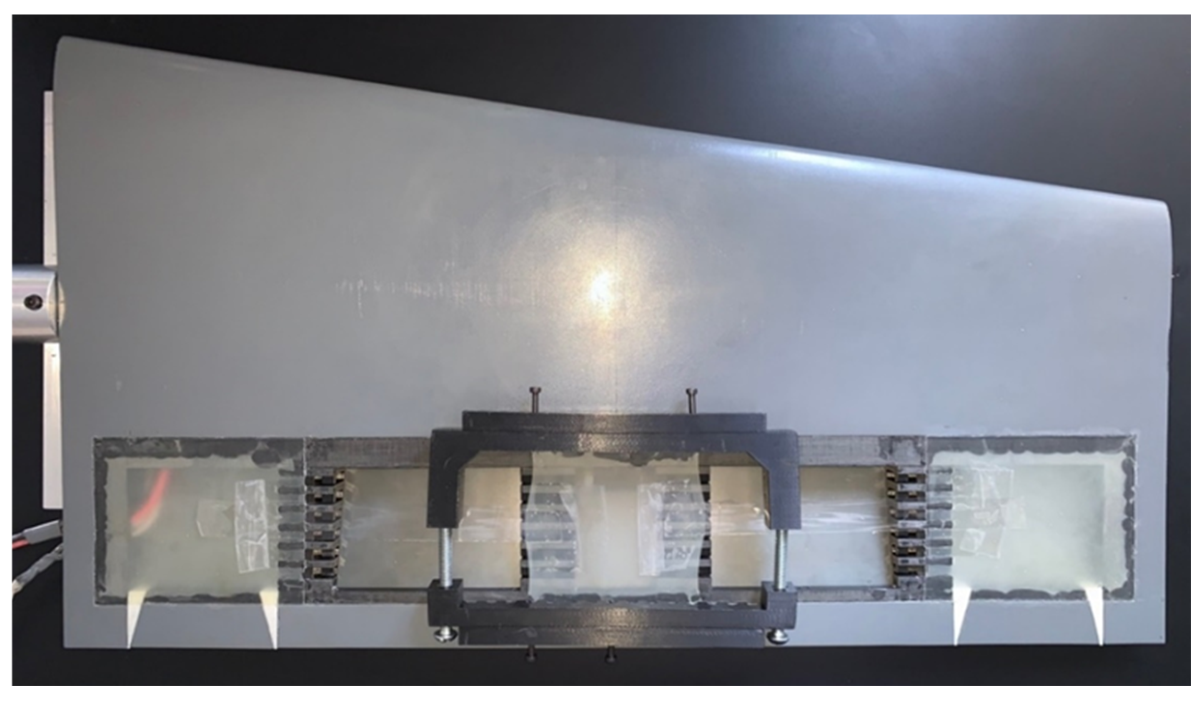
2.1. Prototyping the UAS-S45 Wing Section and Its ETMs
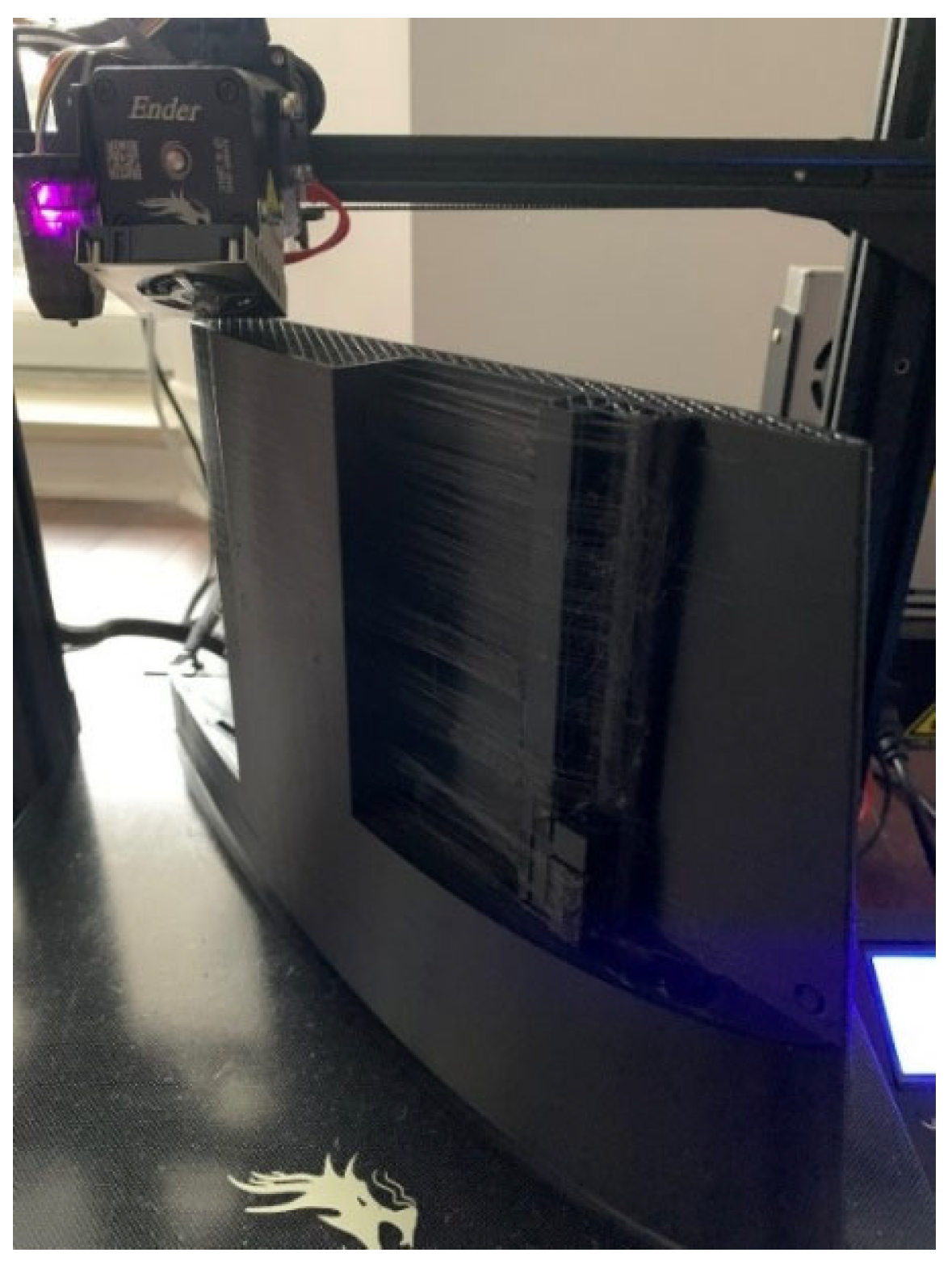
Prototyping processes have advanced significantly with the advent of 3D printers. This manufacturing technology has revolutionized the industry, making prototyping more accessible, easier and significantly less expensive than before. Most of the morphing wing prototypes in the literature have been fabricated using 3D printing [29,38,39]. Three-dimensional printing is an additive manufacturing process that has offered a fast and cost-efficient approach to manufacturing models for wind tunnel testing. It creates a three-dimensional object by depositing melted polymer layer by layer. The process begins with designing the object in CAD software (SolidWorks 2021). The design is then processed by a slicer, software that sets printing parameters and object orientations. The slicer divides the object into layers of defined thickness and generates G-codes, which are sent to the 3D printer (Ender 3 Max, Creality, China). The machine interprets these G-codes to control a heated nozzle that extrudes the polymer filament, “drawing” the object line by line and layer by layer.
The 3D printing parameters are critical for determining the mechanical properties and surface finish of the printed object, while the orientation of the object during printing is equally crucial. Similar to conventional composite materials, the mechanical properties of 3D-printed objects are anisotropic. In composite materials, fibers aligned in the direction of the applied load exhibit superior mechanical properties to those aligned in the perpendicular direction of the applied load. Likewise, 3D-printed objects, constructed layer by layer and line by line, display mechanical behavior resembling that of composites. In this case, the melted filament serves simultaneously as a fiber, as well as a matrix. Forces applied perpendicular to the layers can cause delamination, as the interface between layers, rather than the continuous fibers, must bear the load. This fact highlights the importance of optimizing printing parameters and arrangements to achieve desired mechanical performance. Figure 4 shows the vertical and horizontal arrangements.
As shown in Figure 4, each layer in 3D printing has a specific height (∆h), representing a 2D slice of the studied object. Each layer is supported by the layer directly beneath it. However, if an object contains a cantilever or an overhanging part, the first layer of the cantilever will lack underlying support. To address this issue, the slicer automatically generates a block of support material beneath the overhang part. These supports are typically considered as waste material and are removed during post-processing. Optimizing the orientation and positioning of the object can significantly improve its mechanical properties while reducing printing costs and time by minimizing the need for support structures.
In this study, the vertical arrangement is chosen for printing due to the wing’s curved upper and lower surfaces. Printing these surfaces with greater accuracy is more easily achieved using the vertical orientation than with a horizontal arrangement. Figure 5 shows the vertically arranged wing section during its 3D printing.
The material used for the wing section is PLA+, an enhanced version of regular PLA with additives that improve surface finish and simplify the printing process. The primary properties of PLA+ are provided in Table 1, as specified by the filament manufacturer [40].
Based on the results obtained from the structural analysis in the previous work [37], the material selected for the ETMs was nylon. Nylon’s exceptional mechanical properties made it an ideal material for structural components in the elephant trunk mechanism. Its high tensile strength and flexibility support material elastic deformation during flight, while its low friction coefficient ensures smooth cable motion within its tooth-like components. Additionally, nylon’s light weight reduced the mechanism’s overall mass, enhancing energy efficiency and minimizing aerodynamic loads [37]. Table 2 depicts the nylons’ material properties.
The ETMs were printed in vertical direction in the same way as for the wing box, to ensure the highest level of precision. They were produced in batches (containing 6 ETMs) to enhance printing accuracy and maintain material uniform shapes. Figure 6 illustrates the printed ETMs.

2.2. Printing Setup

The final part’s quality and functionality are greatly influenced by the printing parameters. The surface smoothness, dimensional accuracy and mechanical characteristics of the printed product are directly impacted by variables such as layer height, nozzle temperature, printing speed, infill density and cooling parameters. For example, higher nozzle temperatures can improve layer adhesion at the expense of possible material deterioration, whereas lower layer heights produce smoother surfaces but increase the printing times. Optimizing the infill pattern and density according to its intended use is crucial because these factors also affect the part’s weight and structural integrity. Adjusting these factors not only guarantees excellent part quality, but it also minimizes material waste and production time. The main printing parameters used in this study are presented in Table 3.
To reduce weight, cost and printing time, slicer software offers an infill feature that hollows out the interior of the part and replaces it with a geometrically and mechanically stable structures, such as cubic grids, triangles, or honeycomb patterns. This technique significantly decreases the number of printed lines per layer, reducing printing time and, most importantly, minimizing structural weight. Additionally, the infill structure enhances the part’s stiffness, ensuring that the part maintains its strength while using less material. In this study, a triangular infill pattern was used for the wing box, as shown in Figure 7. By optimizing the printing parameters, the printing process was completed in a total time of 21 days, and consumed approximately 2 kg of PLA+ material.

2.3. Post-Printing

After printing the main wing section and the ETMs, they were installed in the SMTE flap section. Subsequently, the wing section prototype underwent a meticulous post-processing phase to enhance its surface quality. Sanding was performed to remove the visible demarcations and irregularities created by the layering effect of the 3D printing process. This step ensured a seamless and smooth surface, critical for reducing surface roughness, and avoiding any unintended aerodynamic effects during testing. Once the sanding was completed, the wing section was painted with two layers of automotive-grade spray paint to reach this gloss finish. This final step ensured the prototype’s readiness for wind tunnel testing, as surface smoothness is crucial for accurate aerodynamic measurements and performance evaluation. Figure 8 shows the wing section before and after painting.
As shown in Figure 8b, the surface exhibits a smooth, polished finish, making it suitable for subsequent wind tunnel tests. Additionally, Figure 8b illustrates the allocated space for the actuation system located at the leading edge of the wing, covered by a magnetic fairing designed to embed the wiring and actuation servo motors. This fairing ensures a smooth aerodynamic surface by eliminating external fasteners, which is particularly critical for preserving flow integrity during wind tunnel testing. The localized magnetic field prevents interference with the servo motors, maintaining both mechanical stability and electronic reliability.

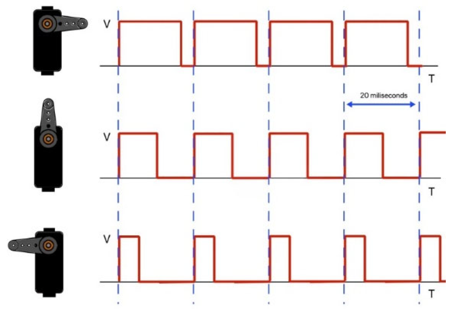
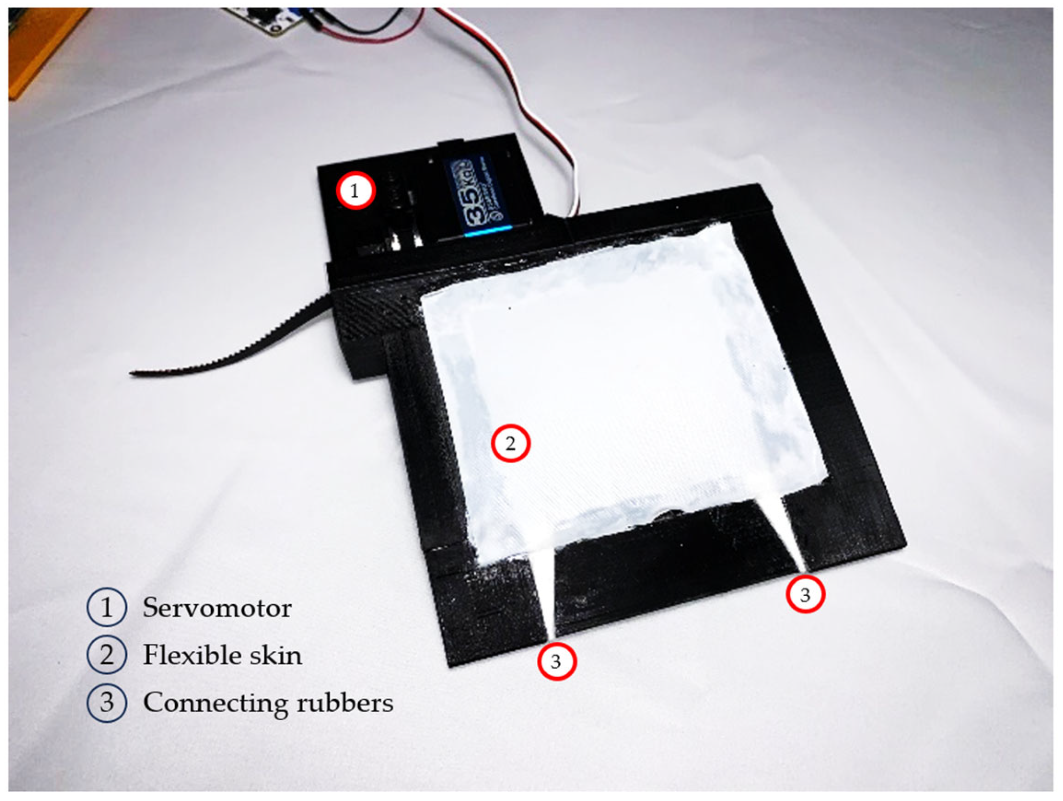
2.4. Actuation Control System

The wing section was fully assembled with its four servo motors, cables, Gate Tooth 2 (GT2) pulleys and wiring harness. The wiring harness was carefully arranged and secured to manage the bulkiness within the actuation housing, ensuring an organized layout. Figure 9 shows the assembled wing section, highlighting the placement of the servo motors, GT2 pulleys, cables and wiring, and their fixed positions.
The SMTE flap actuation with ETMs was achieved by applying a horizontal tensile force to the cables using four servo motors, one for each of the four ETMs. These motors are highly precise and strong, capable of applying and maintaining adequate torque. Each servo motor typically has three terminals: Common Collector Voltage (VCC), Ground (GND) and Pulse With Modulation (PWM). The PWM terminal receives a 50 Hz square wave signal (ranging from 0 V to 5 V in this study) sent every 20 milliseconds, where the pulse width represents the input data (Figure 10).
The larger the pulse is, the more the shaft rotates counterclockwise and vice versa. Therefore, to obtain a certain shaft position and maintain it, a constant PWM signal should be provided continuously. To transfer the shaft torque into a linear force, GT2 pulleys are used. Figure 11 shows the pulleys embedded in the wing box.

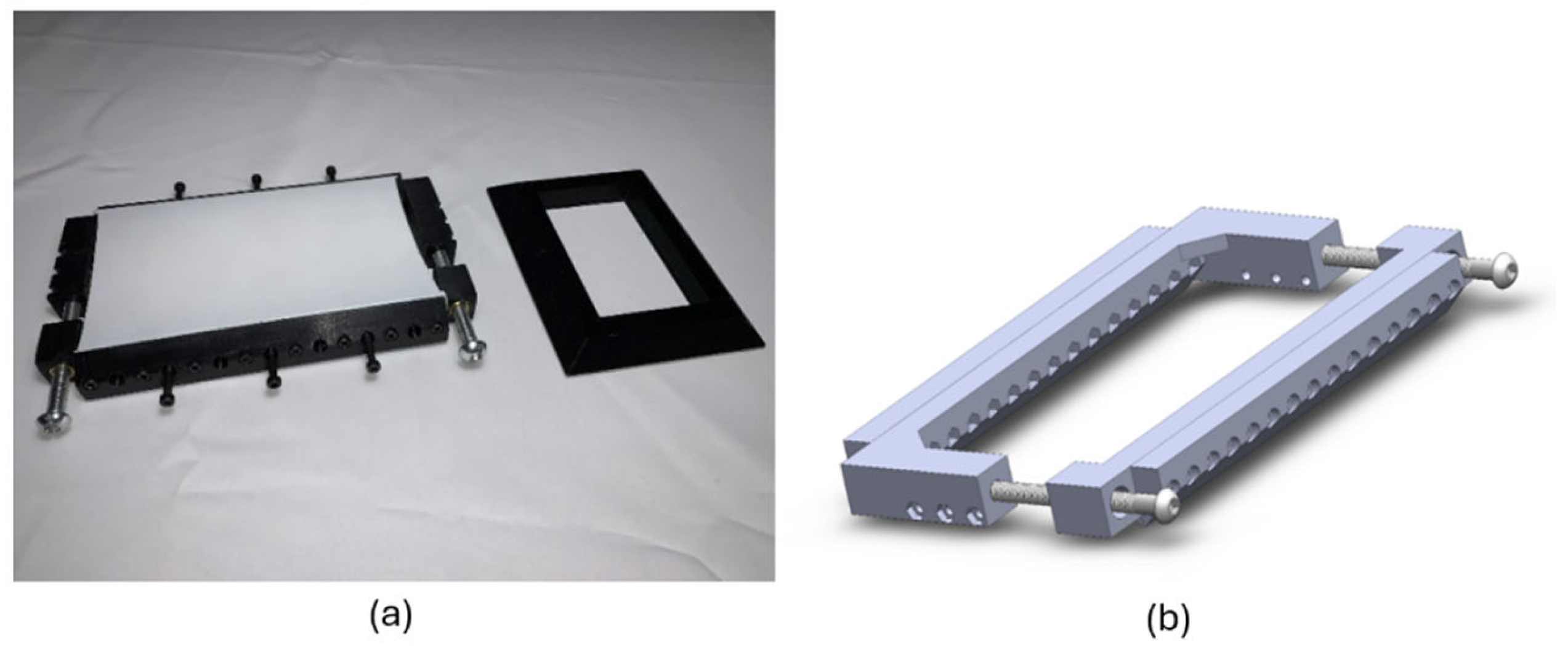
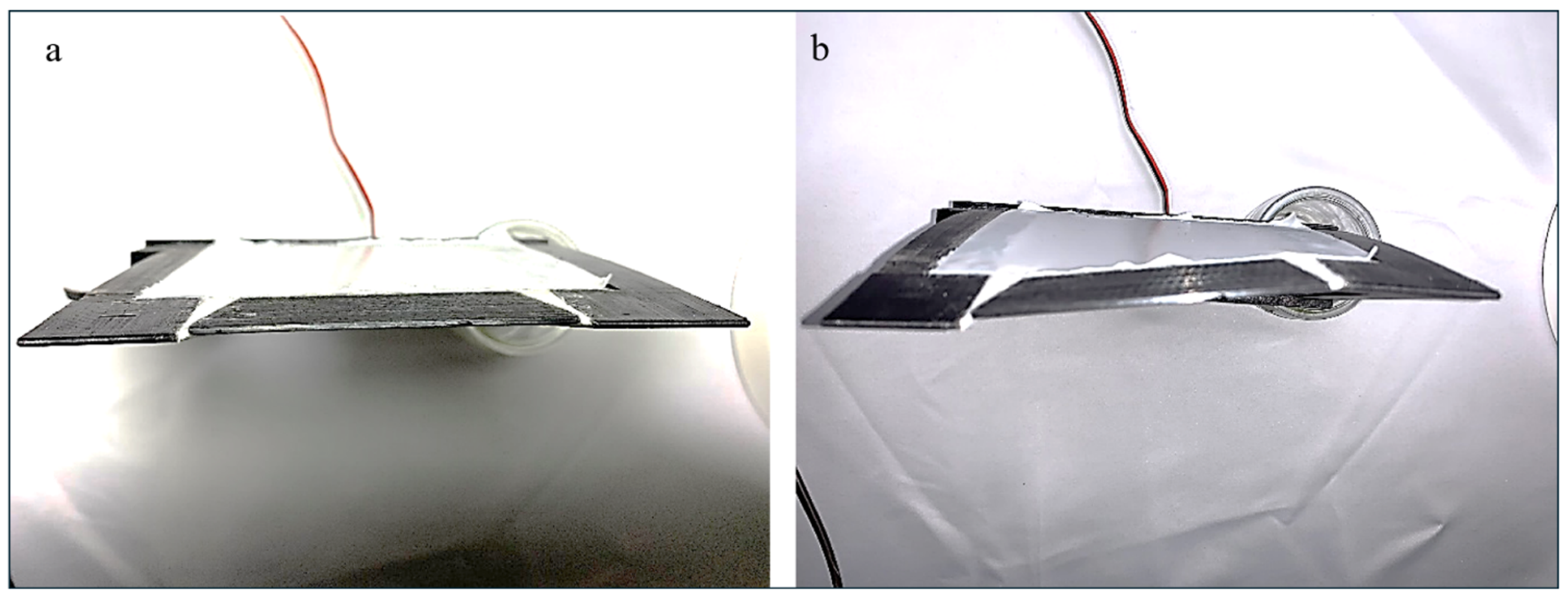
2.5. Implementation of Flexible Skin

The SMTE flap is composed of two main components: (1) the middle flap section, which undergoes downward bending deformations; and (2) the transition sections on the right and left sides, which adapt to the deformation of the middle flap. The transition sections experience twist deformation due to their attachment to both rigid wing structure and the SMTE flap. Consequently, these sections require enhanced flexibility of the skin material. To accommodate complex deformation patterns, a flexible skin material with suitable mechanical properties was selected to allow elasticity for tension in the upper skin and compression in the lower skin.
In previous work [37], two materials were tested for the skin: (1) Thermoplastic Polyurethane (TPU), an elastic polymer widely used in 3D printing; and (2) silicone rubber. A preliminary skin analysis was conducted in ANSYS 2021 R2 software to evaluate the suitability of these materials (see [37] for more details). The TPU exhibited yielding under tension in long runs, likely due to stress relaxation. This behavior was attributed to the release of residual stresses induced during manufacturing when subjected to a constant constraint over time, even within the elastic limit. In contrast, in terms of stretchability and elongation, silicone rubber was an extremely soft and flexible material. Its extended fatigue resistance made it a very good option for morphing wings, as repeated deformations during flight require a material with a very strong fatigue resistance. As a result, it retained its flexibility through repeated morphing without a noticeable material deterioration. Therefore, it demonstrated an excellent performance in supporting the morphing capabilities of the transition sections. Based on these findings, the TPU was replaced with silicone rubber for the skin material. Table 4 summarizes the material properties of silicone rubber.
However, even with silicone rubber, the buckling contraction on the wing lower surface remained unchanged, and the creation of waves on the lower skin was observed. This buckling of the skin was due to its low stiffness and high slenderness ratio. In the structural analysis, for a longitudinal compression of a column, slenderness is defined as the ratio between the section and the length of the column. The higher this ratio is, the more the structure tends to buckle. The slender ratio is given by the following:
λ = l I / A
where l   is the effective length, I denotes the second moment of inertia and A is the section of the column.
To address the buckling issue on the wing lower surface, a solution was obtained without altering the skin material. Since buckling occurs only under compression, the solution was to maintain tension within the working range of the skin. To ensure uniform tension across the entire skin and to maintain consistent tension across all skin panels, a screw-driven pre-tensioning device was designed and 3D printed. This device securely grasps both sides of the skin panel and, by turning two long screws, the distance between the jaws increases, thereby applying uniform tension along the panel. The applied tension can then be accurately measured using a caliper. Figure 12 illustrates the pre-tensioning device.
As shown in Figure 12, the skin was first laid down using the pre-tensioning device. It was clamped between the two jaws and then tensioned by tightening the long screws. An elongation of 40% was applied, which corresponded to 32 mm for a 75 mm skin panel at rest. After applying the intended tension to the skin, it was secured in its designated position using cyanoacrylate glue, which was precisely applied with surgical syringes equipped with non-sharp needles. Figure 13 shows the procedure for attaching the SMTE skin to the flap.

2.6. Graphical User Interface (GUI)

To control the deformation of the morphing wing, the LABVIEW 2021 software was used that allowed for the design of a graphical user interface (GUI) and communication with external devices via USB or serial ports. LABVIEW is typically used with data acquisition cards provided by National Instruments. However, in this study, an Arduino Uno was utilized, which had a resolution of 10 bits, suitable for this case, and which can handle PWM signals on certain GPIO (General Purpose Input Output) pins. The LINX library was utilized to control the Arduino with the LabVIEW interface.
Since each elephant trunk mechanism is independent and therefore has its own servo motor, the tension between the cables cannot be the same without calibration. The program includes an adjustment section with which each motor can be controlled separately, while the flap is managed via the Global Angle Control section. The serial port setting allows the selection of the communication port for the Arduino board. Finally, the servo pin number option allows the selection of the PWM GPIO terminals where each motor is connected. Figure 14 illustrates this GUI.
A precision dial indicator was used to calibrate the ETMs. The calibration process was the following:
The wing was placed flat on the lower skin on a flat surface (measuring marble), with the flap section extended on a cantilever.
It was then clamped to the marble, and the precision dial was positioned vertically on the trailing edge.
The wing was then connected to the Arduino board and the power supply, and the Morphing Wing Controller program was initiated.
The value of the slider corresponding to the ETM being measured with the precision dial was adjusted.
This value was incremented by the minimum amount until the needle on the dial moved.
The value was then incremented backwards, and the reading was recorded.
The final value was the calibration value used to zero the deflections of their corresponding ETM. Each ETM must have its own calibration value. To calibrate each ETM, all the other ETM adjustment sliders should be set to zero, which ensures that only the tension of the measured ETM is considered when reading the dial. There should be four calibration values for the wing; however, disassembling the servo motors cancels the calibration and, for this reason, the calibration process must be repeated.
To test the Morphing Wing Controller program and make its adjustments, the wiring harness is connected to the Arduino board as shown in Figure 15.

3. Results and Discussion

3.1. Pre-Wind Tunnel Evaluations

After the full assembly of the morphing wing, including the 3D-printed wing box, embedded ETMs, internal actuation system and flexible skin, the feasibility of the deformation was tested for its various magnitudes. Two main goals must be achieved: 1—ensuring the smooth deformation of the ETMs; and 2—maintaining the flexibility of the skin, particularly in the transition sections, where twist deformations occur.
Prior to testing the full assembly, each critical component was evaluated independently, which included examining the deformation behavior of the ETMs and the performance of the transition section. Figure 16 illustrates an ETM after undergoing deformation.
As shown in Figure 16, the skin deforms smoothly without any signs of buckling on the wing lower surface, which is attributed to the pre-tensioning applied to the skin prior to its attachment to ETM, as discussed in Section 2.5. Furthermore, the deformation of the ETM was smooth and aligns very well with the results obtained from the structural analysis presented in [37].
Another critical component of the SMTE flap system is its transition sections. These sections were located between the solid wing box and the ETM on the left and right sides of the SMTE flap. The transition sections were covered with flexible skin, which plays a vital role in connecting the morphing section to the solid wing box. Due to this connection, twist morphing occurred in the transition sections, making the flexible skin essential for accommodating the deformation while maintaining its structural integrity. Additionally, the twist morphing in the transition sections also affected the flaps’ solid edges. To mitigate the deformation and reduce stress concentrations at the flaps’ solid edges, two triangular flexible rubber components with the same cross-section as the flap edge were incorporated. These rubber components effectively moderated the deformation and enhanced the durability of the solid edges. Figure 17 illustrates the experimental setup for testing the transition section with its corresponding components, while Figure 18 depicts the transition sections before and after morphing.
As illustrated in Figure 18a, the connecting rubber components are incorporated along the solid edge. These components effectively smooth out the deformation of the transition section, as shown in Figure 18b. While a simple solid connection, over time, would increase the likelihood of failure in the transition sections, incorporating these flexible connections mitigates this risk by accommodating deformation. Furthermore, Figure 18b also shows that the flexible skin exhibits smooth and consistent behavior throughout the morphing process, enhancing the overall reliability of the system.

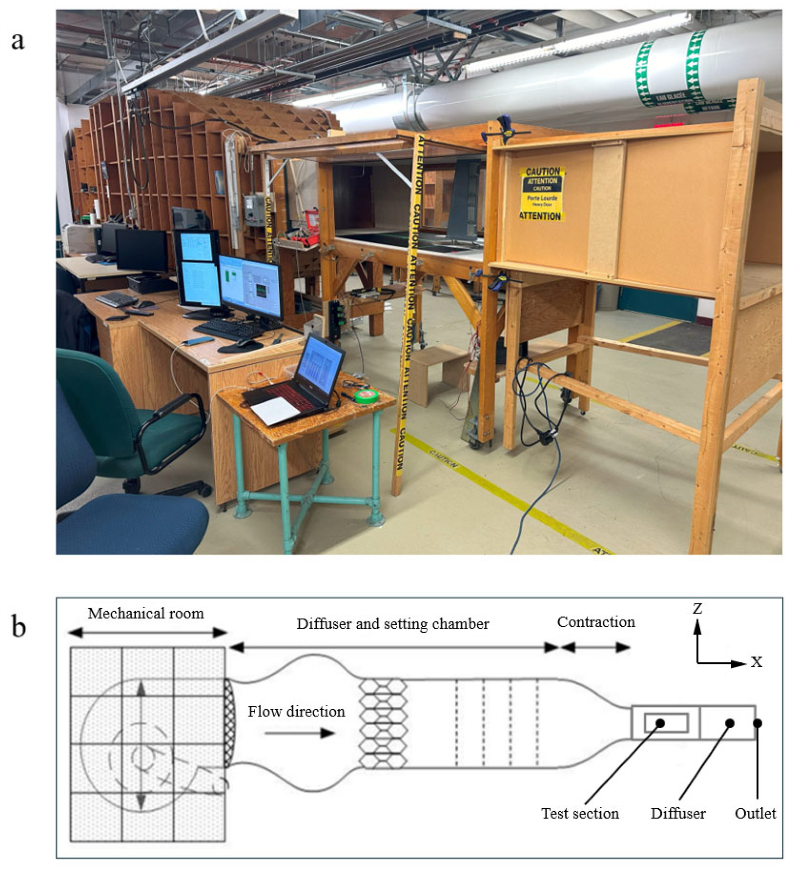
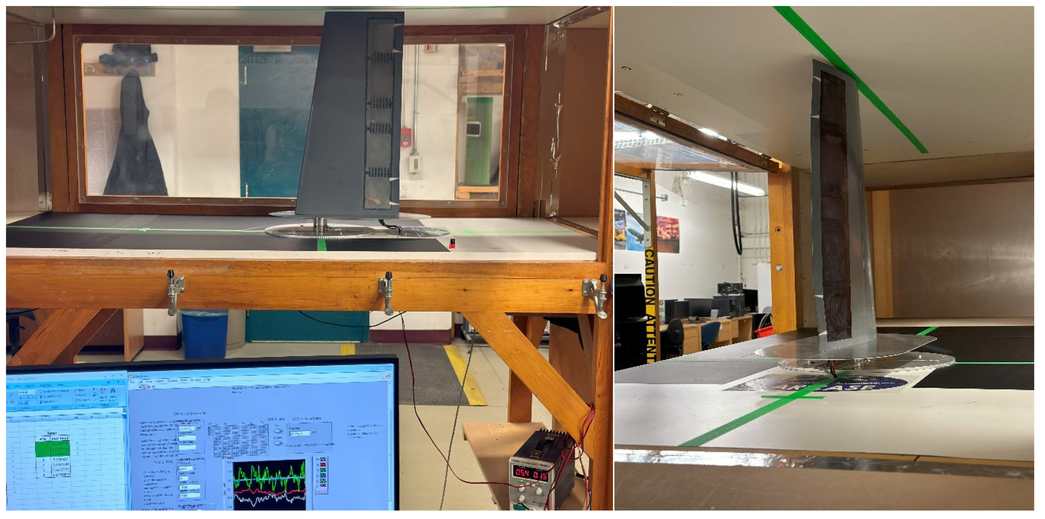
3.2. Price–Païdoussis Subsonic Wind Tunnel

The final test of the complete assembly of the morphing wing was conducted using the Open Return Price–Païdoussis subsonic wind tunnel at LARCASE laboratory, depicted in Figure 19a. As illustrated in detail in Figure 19b, the wind tunnel is composed of a centrifugal fan, a diffusing and settling chamber, a contraction section, and a test chamber or test section. Two inlets on either side of the centrifugal fan allow the air supply to enter the wind tunnel. Within the sealed section, the engine and centrifugal fan are shielded from dust particles.

3.3. Wind Tunnel Test Preparation

The calibration phase, which involved determining the flow parameters inside the test chamber, was a crucial step to complete prior to experimental testing. The primary parameters used to describe the flow in a wind tunnel test included the total, static and dynamic pressures; the temperature variation during the test; the controlled flow speeds; and the Reynolds number. Temperature and pressure values are essential for calculating air density and flow rate. In the wind tunnel, temperature was measured using a Type K thermocouple sensor with an accuracy of ±0.5 °C. The physical forces were digitized using a National Instruments USB-6210 multifunction data acquisition system, enabling the software to process the data.
After calibrating the wind tunnel, the prototyped morphing wing was mounted in the test section using appropriate fixations. The test section had dimensions of 0.62 m in height, 0.91 m in width and 1.83 m in length, with a maximum speed capacity of 0.1 Mach (35 m/s). The air speed used in the previous aerodynamic study, and to be used in the wind tunnel for validation, was 28.3 m/s, well below the maximum limit of 50 m/s. Figure 20 shows the UAS-S45 morphing wing section installed in the wind tunnel.
When models are tested in wind tunnels for performance evaluations, the airflow they encounter differs from the conditions they would experience in an open-air environment [41]. Therefore, wind tunnel experiments have several limitations, primarily related to the thickness of the boundary layer, the scale and size of the models, obstruction effect adjustments and levels of turbulence flow intensities, even for the same flow conditions. The two primary sources of error in subsonic flow experimentation are (1) alterations in the flow field caused by flow confinement around the body; and (2) the flow interaction with the wind tunnel boundary (closed walls), which is represented by the obstruction, and wall interference.
The corrections of these flow effects in wind tunnel data can be addressed through various methods. To reduce uncertainties in the results, model scaling is often applied whenever it is feasible to achieve a blockage area ratio of smaller than 10%. Despite the benefits of reduced-scale models for mitigating interference and blockage effects, their application can give inaccurate results. In this study, the wing was positioned at the center of the test section, as shown in Figure 20. The prototype model was scaled by a factor of 0.466 to accommodate the test section dimensions and the resulting blockage ratio was calculated to be 5.2%, which was below the acceptable blockage limit. Table 5 shows the air conditions inside the test section.

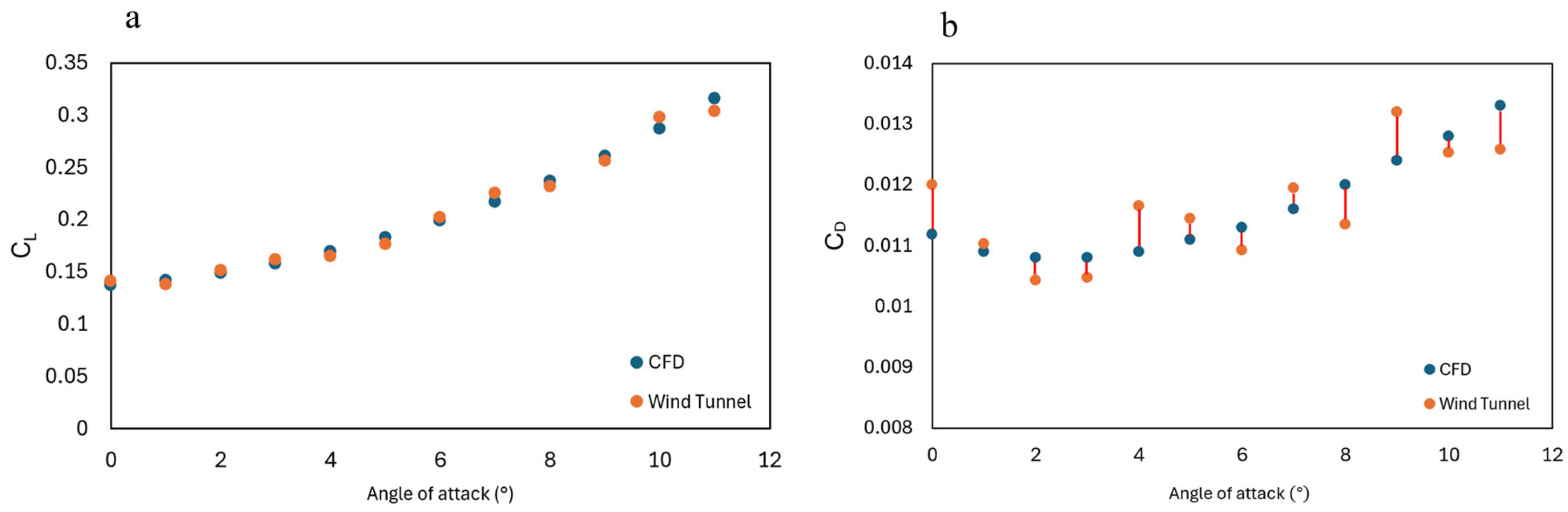
3.4. Wind Tunnel Test Results—Comparison of Numerical and Experimental Data

A total of 11 distinct test sets were conducted in the wind tunnel, for various angles of attack and flap deflections. As the angle of attack increased, the deflection of the SMTE flap decreased. The flap deflection values at each angle of attack were obtained from a prior aerodynamic study. To ensure the consistency of the results, Computational Fluid Dynamics (CFD) simulations were conducted using OpenFOAM, replicating the flow conditions and scaling of the wind tunnel experiments. The computational domain dimensions were selected to match the wind tunnel test section, with a height of 0.62 m, a width of 0.91 m and a length of 1.83 m. Therefore, the effects of the tunnel walls on the flow field are inherently captured in the CFD model.
The simulations were conducted using the same free-stream velocity as in the experiments, 28.3 m/s, corresponding to the same Reynolds number based on the reference chord length. The fluid was modeled as incompressible, and the Reynolds-Averaged Navier–Stokes (RANS) equations were solved to capture the steady-state flow behavior. To account for turbulence effects, the Spalart–Allmaras turbulence model was employed.
After conducting a mesh independence study, the final computational grid consisted of approximately 4,465,431 cells. Boundary conditions included uniform velocity inlet, static pressure outlet and no-slip conditions on solid surfaces. These simulations allowed for a direct comparison between the experimental and CFD results.
The results from both the wind tunnel tests and CFD simulations, along with their associated errors, are presented in Table 6.
Table 6 shows that the numerical and experimental results are in very good agreement for both CL and CD. The maximum error occurred in the CD results, reaching up to 7.3%, while the maximum error for CL is 4.06%. These differences arise from various uncertainty factors in the wind tunnel tests, with drag force being more affected than lift force. However, both errors for CL and CD remain within an acceptable range and demonstrate strong agreement with the numerical results. Figure 21 presents the variations in CL and CD with the angle of attack along with their relative errors.
As shown in Figure 21, both data sets exhibit an increasing trend with the angle of attack. However, the rate at which CL increases with the variation in the angle of attack is higher than that of CD. This observation also validates the findings of our recent aerodynamic study [36], which reported similar variation trends for both CL and CD.

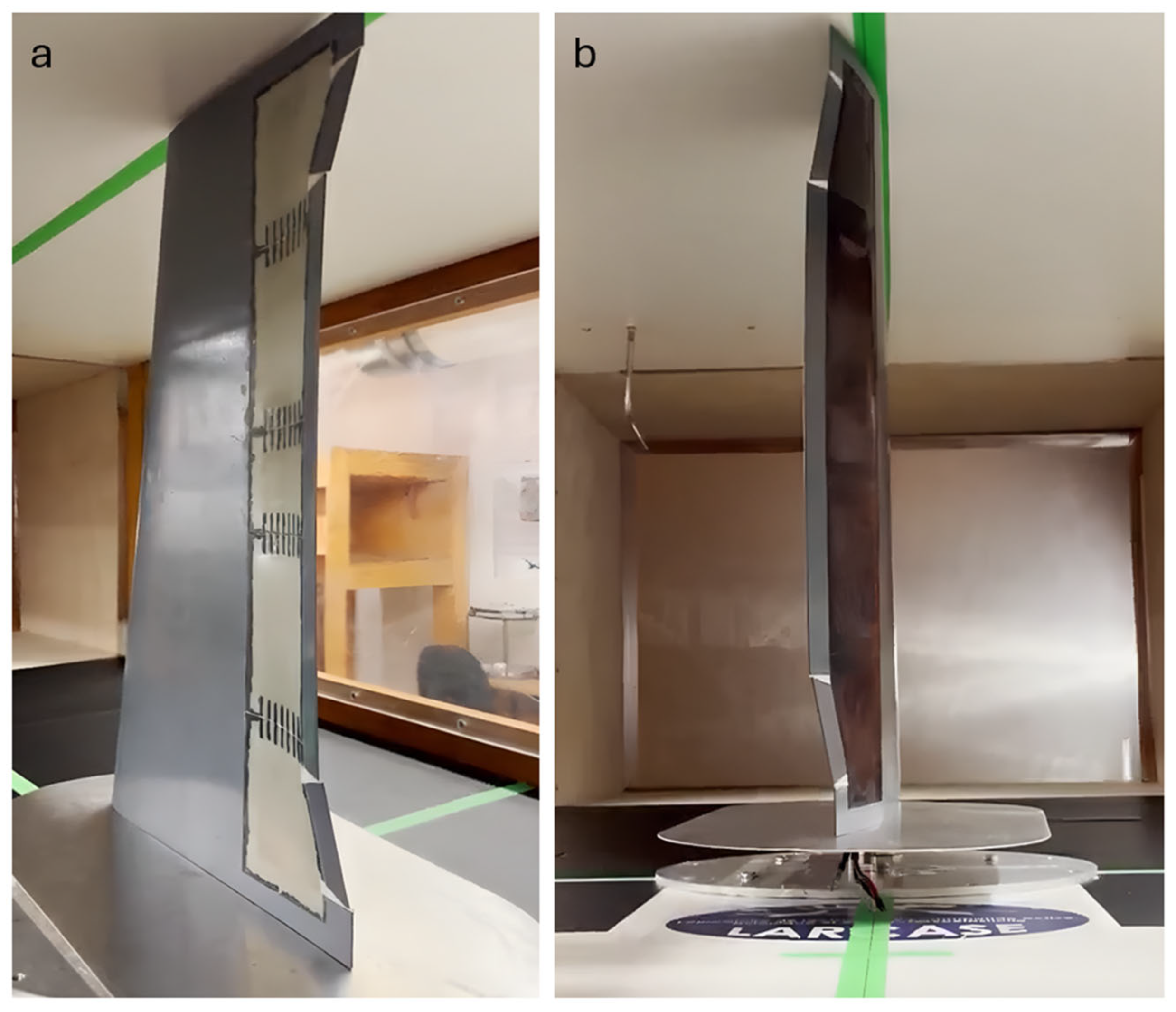
3.5. Wind Tunnel Test Results—Structural Feasibility of ETMs and Flexible Skin

Beyond validating the numerical results, the wind tunnel tests also aimed to assess the structural integrity and feasibility of the ETMs and flexible skin for SMTE flap morphing. Throughout all 11 tests, the deformation of the ETMs and the performance of the flexible skin were carefully observed. The results of the structural analysis in [37] showed that the ETM could achieve the minimum required deflection of 66 mm. This was confirmed by experimental tests, where the vertical flap deflection reached 30.815 mm (Table 6), which corresponds to 66.13 mm when scaled by a factor of 0.466. Figure 22 presents the SMTE flap after its morphing.
As mentioned in Section 2.5, the buckling behavior of the flexible skin was mitigated by pre-tensioning the skin before attachment to the SMTE flap’s lower surface using a screw-driven pre-tensioning device. Figure 22a illustrates the lower surface of the SMTE flap at its maximum deflection. As shown in this figure, no buckling signs are present, and the skin maintains a smooth surface across the entire flap, demonstrating the effectiveness of the flexible skin. Additionally, through continuous variation in the SMTE flap deflection angle, it was confirmed that all four ETMs, along with the connecting rubbers in the transition sections, worked properly without any malfunctions (Figure 22b).

4. Conclusions

Based on the successful aerodynamic and structural analyses conducted in previous studies, the present work aimed to experimentally validate the obtained numerical results and therefore develop a practical model of the proposed morphing designs: the seamless morphing trailing Edge (SMTE) flap and the elephant trunk mechanism (ETM). The final stage of this project involved prototyping and testing the feasibility of the SMTE flap and the ETM-based actuation system, resulting in the development of a morphing trailing edge flap for the UAS-S45 wing.
The prototyping process comprised multiple stages, including the 3D printing of the wing box and the ETMs, integration of the actuation system within the wing structure, attachment of the silicone rubber flexible skin to the SMTE flap and the development of a control system using a graphical user interface (GUI). A series of tests were conducted to assess the feasibility and reliability of various structural components. These tests included individual ETM evaluations, transition section tests and flexible skin assessments prior to full-wing assembly.
Upon successful completion of these tests, the design’s reliability and practicality were confirmed. The experimental results validated the smooth deformability of the ETMs and of the transition sections, aligning with the numerical findings from previous structural analyses. Additionally, a key issue identified in prior studies—skin buckling on the lower flap surface—was effectively mitigated by employing a pre-tensioning tool to stretch the skin before attachment. To further enhance the performance, flexible rubber connectors were introduced in the transition sections to minimize stress concentrations along the flap’s solid edges.
Following its full assembly, the morphing wing model underwent wind tunnel testing. A total of 11 tests were conducted, varying both the angle of attack and flap deflection angles. To complement these experiments, Computational Fluid Dynamics (CFD) simulations were performed under identical flight conditions, test constraints and parameters. The lift coefficient (CL) and drag coefficient (CD) obtained from CFD closely matched the experimental results, with maximum discrepancies of 4.06% and 7.3%, respectively. These variations are within acceptable ranges and underscore the reliability of the numerical models. This strong agreement with experimental data confirmed the validity of the aerodynamic findings obtained in the previous study.
Furthermore, the structural performance of the ETM was quantitatively validated through both numerical and experimental results. Previous structural analyses demonstrated the ETM’s ability to achieve a minimum required flap tip deflection of 66 mm. In the wind tunnel experiments, the SMTE flap exhibited a vertical displacement of 30.815 mm. Given that the test model was constructed at 46.6% of the full-scale size, this measured displacement translates to 66.13 mm in actual scale, thereby confirming the ETM’s effectiveness in achieving the target deflection range.
This research successfully validated the aerodynamic and structural performance of the proposed morphing wing model. Future studies will focus on exploring additional aerodynamic phenomena, including flow separation, transition and dynamic stall. These aspects will be investigated in wind tunnel experiments using advanced measurement techniques, such as Particle Image Velocimetry (PIV) and smoke injection, further showing the advantages of the SMTE flap design.

Author Contributions

Conceptualization, M.H.N.; methodology, M.H.N.; software, M.H.N. and T.S.; validation, M.H.N. and T.S.; formal analysis, M.H.N. and T.S.; investigation, M.H.N. and T.S.; resources, M.H.N.; data curation, M.H.N. and T.S.; writing—original draft preparation, M.H.N.; writing—review and editing, M.H.N. and R.M.B.; visualization, M.H.N.; supervision, R.M.B.; project administration, M.H.N. and R.M.B.; funding acquisition, R.M.B. All authors have read and agreed to the published version of the manuscript.

Funding

This research received no external funding.

Institutional Review Board Statement

Not applicable.

Informed Consent Statement

Not applicable.

Data Availability Statement

The data presented in this study are available on request from the corresponding author.

Acknowledgments

We gratefully acknowledge the Natural Sciences and Engineering Research Council of Canada (NSERC) for their vital support through the Tier 1 Canada Research Chair in Aviation Modelling and Simulation Technology. We also extend our sincere thanks to the team at Hydra Technologies in Mexico and the CREATE-UTILI Program for their generous contributions. A special note of appreciation goes to Oscar Carranza Moyao for his dedicated support and valuable assistance during the wind tunnel experiments.

Conflicts of Interest

The authors declare no conflicts of interest.

References

  1. Ameduri, S.; Concilio, A. Morphing wings review: Aims, challenges, and current open issues of a technology. Proc. Inst. Mech. Eng. Part C J. Mech. Eng. Sci. 2023, 237, 4112–4130. [Google Scholar] [CrossRef]
  2. Barbarino, S.; Bilgen, O.; Ajaj, R.M.; Friswell, M.I.; Inman, D.J. A review of morphing aircraft. J. Intell. Mater. Syst. Struct. 2011, 22, 823–877. [Google Scholar] [CrossRef]
  3. Wickenheiser, A.M.; Garcia, E. Aerodynamic modeling of morphing wings using an extended lifting-line analysis. J. Aircr. 2007, 44, 10–16. [Google Scholar] [CrossRef]
  4. Jo, B.W.; Majid, T. Aerodynamic analysis of camber morphing airfoils in transition via computational fluid dynamics. Biomimetics 2022, 7, 52. [Google Scholar] [CrossRef]
  5. Körpe, D.S. Aerodynamic Modelling and Optimization of Morphing Wings. Ph.D. Thesis, Turkish Aerospace Industries, Ankara, Türkiye, 2014. [Google Scholar]
  6. Sicim Demirci, M.S.; Pecora, R.; Chianese, L.; Viscardi, M.; Kaya, M.O. Structural Analysis and Experimental Tests of a Morphing-Flap Scaled Model. Aerospace 2024, 11, 725. [Google Scholar] [CrossRef]
  7. Soneda, K.; Yokozeki, T.; Imamura, T.; Tsushima, N. Aero-structural analysis of corrugated morphing wing with spanwise camber change. In Proceedings of the AIAA Scitech 2020 Forum, Orlando, FL, USA, 6–10 January 2020; p. 0450. [Google Scholar]
  8. Obradovic, B.; Subbarao, K. Modeling of flight dynamics of morphing wing aircraft. J. Aircr. 2011, 48, 391–402. [Google Scholar] [CrossRef]
  9. Xiao, K.; Chen, Y.; Jiang, W.; Wang, C.; Zhao, L. Modeling, simulation and implementation of a bird-inspired morphing wing aircraf. In Proceedings of the 2019 3rd International Conference on Robotics and Automation Sciences (ICRAS), Wuhan, China, 1–3 June 2019; pp. 238–243. [Google Scholar]
  10. Liauzun, C.; Le Bihan, D.; David, J.-M.; Joly, D.; Paluch, B. Study of Morphing Winglet Concepts Aimed at Improving Load Control and the Aeroelastic Behavior of Civil Transport Aircraft; Aerospace Lab: Bangalore, India, 2018; pp. 1–15. [Google Scholar]
  11. Dimino, I.; Flauto, D.; Diodati, G.; Concilio, A.; Pecora, R. Actuation system design for a morphing wing trailing edge. Recent Pat. Mech. Eng. 2014, 7, 138–148. [Google Scholar] [CrossRef]
  12. Wang, Q.; Xu, Z.; Zhu, Q. Structural design of morphing trailing edge actuated by SMA. Front. Mech. Eng. 2013, 8, 268–275. [Google Scholar] [CrossRef]
  13. Campanile, L.; Sachau, D. The belt-rib concept: A structronic approach to variable camber. J. Intell. Mater. Syst. Struct. 2000, 11, 215–224. [Google Scholar] [CrossRef]
  14. Bourchak, M.; Ajaj, R.; Flores, E.S.; Khalid, M.; Juhany, K. Optimum design of a PID controller for the adaptive torsion wing. Aeronaut. J. 2015, 119, 871–889. [Google Scholar] [CrossRef]
  15. Parancheerivilakkathil, M.S.; Pilakkadan, J.S.; Amoozgar, M.; Asadi, D.; Zweiri, Y.; Friswell, M.I. A review of control strategies used for morphing aircraft applications. Chin. J. Aeronaut. 2024, 37, 436–463. [Google Scholar] [CrossRef]
  16. Fonzi, N.; Brunton, S.L.; Fasel, U. Data-driven nonlinear aeroelastic models of morphing wings for control. Proc. R. Soc. A 2020, 476, 20200079. [Google Scholar] [CrossRef] [PubMed]
  17. Moosavian, A.; Xi, F.; Hashemi, S.M. Design and motion control of fully variable morphing wings. J. Aircr. 2013, 50, 1189–1201. [Google Scholar] [CrossRef]
  18. Özel, C.; Özbek, E.; Ekici, S. A review on applications and effects of morphing wing technology on uavs. Int. J. Aviat. Sci. Technol. 2020, 1, 30–40. [Google Scholar] [CrossRef]
  19. Sofla, A.; Meguid, S.; Tan, K.; Yeo, W. Shape morphing of aircraft wing: Status and challenges. Mater. Des. 2010, 31, 1284–1292. [Google Scholar] [CrossRef]
  20. Jha, A.K.; Kudva, J.N. Morphing aircraft concepts, classifications, and challenges. In Proceedings of the Smart Structures and Materials 2004: Industrial and Commercial Applications of Smart Structures Technologies, San Diego, CA, USA, 16–18 March 2004; pp. 213–224. [Google Scholar]
  21. Kota, S.; Osborn, R.; Ervin, G.; Maric, D.; Flick, P.; Paul, D. Mission adaptive compliant wing–design, fabrication and flight test. In Proceedings of the RTO Applied Vehicle Technology Panel (AVT) Symposium, Bonn, Germany, 19–22 October 2009; pp. 1–18. [Google Scholar]
  22. Botez, R.M.; Koreanschi, A.; Gabor, O.S.; Tondji, Y.; Guezguez, M.; Kammegne, J.; Grigorie, L.; Sandu, D.; Mebarki, Y.; Mamou, M. Numerical and experimental transition results evaluation for a morphing wing and aileron system. Aeronaut. J. 2018, 122, 747–784. [Google Scholar] [CrossRef]
  23. Popov, A.V.; Grigorie, L.T.; Botez, R.; Mamou, M.; Mebarki, Y. Closed-loop control validation of a morphing wing using wind tunnel tests. J. Aircr. 2010, 47, 1309–1317. [Google Scholar] [CrossRef]
  24. Carossa, G.M.; Ricci, S.; De Gaspari, A.; Liauzun, C.; Dumont, A.; Steinbuch, M. Adaptive trailing edge: Specifications, aerodynamics, and exploitation. In Proceedings of the Smart Intelligent Aircraft Structures (SARISTU), Proceedings of the Final Project Conference, Moscow, Russia, 19–21 May 2015; pp. 143–158. [Google Scholar]
  25. Ameduri, S.; Concilio, A.; Dimino, I.; Pecora, R.; Ricci, S. AIRGREEN2-clean sky 2 programme: Adaptive Wing technology maturation, challenges and perspectives. Smart Mater. Adapt. Struct. Intell. Syst. 2018, 51944, V001T004A023. [Google Scholar]
  26. Kota, S.; Flick, P.; Collier, F.S. Flight testing of flexfloiltm adaptive compliant trailing edge. In Proceedings of the 54th AIAA Aerospace Sciences Meeting, San Diego, CA, USA, 4–8 January 2016; p. 0036. [Google Scholar]
  27. Zhigang, W.; Xiasheng, S.; Yu, Y.; Wenjie, G.; Daochun, L.; Xiang, J.; Panpan, B.; Qi, W.; Da Ronch, A. Design optimization and testing of a morphing leading-edge with a variable-thickness compliant skin and a closed-chain mechanism. Chin. J. Aeronaut. 2024, 37, 285–300. [Google Scholar]
  28. Communier, D.; Le Besnerais, F.; Botez, R.M.; Wong, T. Design, manufacturing, and testing of a new concept for a morphing leading edge using a subsonic blow down wind tunnel. Biomimetics 2019, 4, 76. [Google Scholar] [CrossRef]
  29. Jia, S.; Zhang, Z.; Zhang, H.; Song, C.; Yang, C. Wind tunnel tests of 3D-Printed variable camber morphing wing. Aerospace 2022, 9, 699. [Google Scholar] [CrossRef]
  30. Ricci, S.; De Gaspari, A.; Riccobene, L. Design, manufacturing and wind tunnel test of a morphing wing based on compliant structures. In Proceedings of the 24th AIAA/AHS Adaptive Structures Conference, San Diego, CA, USA, 4–8 January 2016; p. 1316. [Google Scholar]
  31. Dimino, I.; Galasso, B.; Guida, M.; Miceli, M.; Riemenschneider, J.; Kalow, S.; Luebker, J. Whirl Tower Demonstration of an SMA Blade Twist System. Actuators 2022, 11, 141. [Google Scholar] [CrossRef]
  32. Jeong, J.; Bae, J.-S. Wind tunnel & Flight Test of VCCS Morphing UAV. In Proceedings of the 2022 International Conference on Unmanned Aircraft Systems (ICUAS), Dubrovnik, Croatia, 21–24 June 2022; pp. 1424–1431. [Google Scholar]
  33. Botez, R.M.; Koreanschi, A.; Oliviu, S.G.; Mebarki, Y.; Mamou, M.; Tondji, Y.; Amoroso, F.; Pecora, R.; Lecce, L.; Amendola, G. Numerical and experimental testing of a morphing upper surface wing equipped with conventional and morphing ailerons. In Proceedings of the 55th AIAA Aerospace Sciences Meeting, Grapevine, TX, USA, 9–13 January 2017; p. 1425. [Google Scholar]
  34. Groves-Raines, M.M.; Araujo-Estrada, S.A.; Mohamed, A.; Watkins, S.; Windsor, S.P. Wind tunnel testing of an avian-inspired morphing wing with distributed pressure sensing. In Proceedings of the 2022 International Conference on Unmanned Aircraft Systems (ICUAS), Dubrovnik, Croatia, 21–24 June 2022; pp. 290–299. [Google Scholar]
  35. Salinas, M.F.; Botez, R.M.; Gauthier, G. New validation methodology of an adaptive wing for UAV S45 for fuel reduction and climate improvement. Appl. Sci. 2023, 13, 1799. [Google Scholar] [CrossRef]
  36. Negahban, M.H.; Bashir, M.; Traisnel, V.; Botez, R.M. Seamless morphing trailing edge flaps for UAS-S45 using high-fidelity aerodynamic optimization. Chin. J. Aeronaut. 2024, 37, 12–29. [Google Scholar] [CrossRef]
  37. Negahban, M.H.; Hallonet, A.; Noupoussi Woumeni, M.; Nguyen, C.; Botez, R.M. Structural and Topological Optimization of a Novel Elephant Trunk Mechanism for Morphing Wing Applications. Aerospace 2025, 12, 381. [Google Scholar] [CrossRef]
  38. Moulton, B.C. 3D-Printed Morphing Wings for Controlling Yaw on Flying-Wing Aircraft. Master of Science, Utah State University, Logan, UT, USA, 2021. [Google Scholar]
  39. Rivero, A.E.; Fournier, S.; Heeb, R.M.; Woods, B.K. Design, manufacture and wind tunnel test of a modular FishBAC wing with novel 3D printed skins. Appl. Sci. 2022, 12, 652. [Google Scholar] [CrossRef]
  40. Farnell. PLA+ Filament. Available online: https://www.farnell.com/datasheets/3775310.pdf (accessed on 13 February 2025).
  41. Khalid, M.; Juhany, K.A.; Hafez, S. Computational modeling of the flow in a wind tunnel. Aircr. Eng. Aerosp. Technol. 2018, 90, 175–185. [Google Scholar] [CrossRef]
Figure 1. Schematic of the UAS-S45 wing equipped with a morphed SMTE flap.
Applsci 15 05570 g001
Figure 2. Illustration of the (a) elephant trunk mechanism (ETM), (b) assembly of four ETMs inside the SMTE flap.
Applsci 15 05570 g002
Figure 3. Schematic of the UAS-S45 wing section equipped with an SMTE flap, elephant trunk mechanisms (ETMs), flexible skin and an actuation system.
Applsci 15 05570 g003
Figure 4. Three-dimensional printing layer arrangements, (a) vertical, (b) horizontal.
Applsci 15 05570 g004
Figure 5. Three-dimensional printing of the wing section with vertical arrangement.
Applsci 15 05570 g005
Figure 6. A batch of 3D-printed EMTs.
Applsci 15 05570 g006
Figure 7. Triangular infill pattern of the UAS-S45 wing box.
Applsci 15 05570 g007
Figure 8. Schematics of UAS-S45 wing section, (a) before, (b) after painting.
Applsci 15 05570 g008
Figure 9. The final assembly of the actuation system inside the wing box.
Applsci 15 05570 g009
Figure 10. The correlation between the pulse width and the position of the servo motor.
Applsci 15 05570 g010
Figure 11. Cross-section view of the control system in the wing box with GT2 pulley.
Applsci 15 05570 g011
Figure 12. Schematics of pre-tensioning device for flexible skin. (a) Fabricated model, (b) CAD design model.
Applsci 15 05570 g012
Figure 13. Attachment of the flexible skin on the lower surface of the SMTE flap using the pretension tool.
Applsci 15 05570 g013
Figure 14. Graphical user interface for controlling the deflection of the SMTE flap.
Applsci 15 05570 g014
Figure 15. Electrical diagram of the actuation system.
Applsci 15 05570 g015
Figure 16. ETM after deformation.
Applsci 15 05570 g016
Figure 17. Transition section with its corresponding components.
Applsci 15 05570 g017
Figure 18. Transition section: (a) before, and (b) after morphing.
Applsci 15 05570 g018
Figure 19. Price–Païdoussis subsonic wind tunnel: (a) actual model, (b) schematic of sections with coordinates.
Applsci 15 05570 g019
Figure 20. UAS-S45 morphing wing section installed in the wind tunnel test section.
Applsci 15 05570 g020
Figure 21. Comparison of CFD and wind tunnel results of (a) lift and (b) drag coefficient variations with angle of attack.
Applsci 15 05570 g021
Figure 22. UAS-S45 wing section with SMTE flap after morphing in the wind tunnel: (a) lower surface view, (b) upper surface view.
Applsci 15 05570 g022
Table 1. Physical and mechanical properties of the PLA+.
PropertyValue
Density (g/cm3)1.23
Melt Flow Index (190 °C/2.16 kg)5
Tensile Strength (MPa)63
Elongation at Break (%)20
Flexural Strength (MPa)74
Flexural Modulus (MPa)1973
Heat Distortion Temperature (°C)53
Table 2. Material properties of nylon.
Young’s Modulus (MPa)Poisson’s RatioDensity
(kg/m3)
Yield Strength
(MPa)
29600.41114075
Table 3. Printing parameters.
PropertyValue
Layer height (mm)0.2
Line width (mm)0.4
Wall thickness (mm)2
Top/bottom thickness (mm)2
Infill density (%)30
Printing temperature (°C)200
Build plate temperature (°C)60
Print speed (mm/s)50
Wall print speed (mm/s)15
Build plate adhesion typeBrim
Table 4. Material properties of silicon rubber [37].
Young’s Modulus
(MPa)
Poisson RatioTensile Yield Strength
(MPa)
Density
(kg/m3)
170.510.41230
Table 5. Air properties inside the wind tunnel test section.
Air Density
(Kg/m3)
Temperature
(°C)
Relative Humidity
(%)
Air Speed
(m/s)
Pressure
(kPa)
1.1922.63428.3101.6
Table 6. Comparison of wind tunnel test and CFD results.
AOA
(°)
Flap Vertical Displacement
(mm)
CFDWind TunnelError (%)
CLCDCLCDCLCD
030.8150.13710.01100.14120.012013.987.30
125.1320.14180.01090.13800.011033.031.20
220.6300.14870.01080.15150.010431.693.46
317.5940.15790.01080.16130.010473.913.02
415.0860.16940.01090.16480.011652.396.87
513.4050.18290.01110.17620.011443.403.04
611.4190.19850.01130.20210.010924.043.36
710.7340.21650.01160.22510.011950.883.02
810.0620.23700.01200.23130.011351.025.38
98.0300.26030.01240.25570.013204.066.45
105.1570.28650.01280.29740.012532.182.12
113.0480.31570.01330.30320.012581.935.40
Disclaimer/Publisher’s Note: The statements, opinions and data contained in all publications are solely those of the individual author(s) and contributor(s) and not of MDPI and/or the editor(s). MDPI and/or the editor(s) disclaim responsibility for any injury to people or property resulting from any ideas, methods, instructions or products referred to in the content.

