Abstract
This study investigates a novel anchor-based method for controlled rock fragmentation, designed as an alternative to conventional excavation or explosive techniques. The proposed solution utilizes a specially modified undercut anchor that induces localized failure within the rock mass through radial expansion rather than traditional pull-out forces. Finite Element Method simulations, performed in ABAQUS with an extended fracture mechanics approach, were used to model the initiation and propagation of failure zones in sandstone. The results revealed a two-phase cracking process starting beneath the anchor’s driving element and progressing toward the rock’s free surface, forming a breakout cone. This behavior significantly deviates from conventional prediction models, such as the 45° cone or Concrete Capacity Design methods (cone 35°). The simulations were supported by field tests, confirming both the feasibility and practical advantages of the proposed anchor system, especially in confined or safety-critical environments. The findings offer valuable insights for the development of compact and efficient rock fragmentation technologies suitable for mining, rescue operations, and civil engineering applications.
1. Introduction
Anchorage systems of various types are widely employed in civil engineering [1,2], mining, and underground construction as reinforcement, stabilization, or retaining elements for soil and rock structures [3,4,5,6,7]. Undercutting anchors are commonly utilized in the technology of embedding steel structures into engineered concrete constructions, where they provide reliable mechanical interlocking and high load-bearing capacity essential for structural stability [8,9,10,11,12,13]. One of the primary applications of anchors is the stabilization and protection of excavation walls and slopes against soil displacement or landslides, particularly in areas characterized by steep inclines or geomechanically unstable substrates. In tunneling and mining operations, anchors are used to reinforce the roofs of underground workings, effectively preventing roof collapses and thereby enhancing occupational safety [14,15,16,17]. These systems play a critical role in improving the load-bearing capacity of geological formations and ensuring structural integrity under dynamic and static loading conditions.
In engineering structures, ground anchors are employed to transfer loads from superstructures—such as retaining walls, masts, and foundations—to deeper, load-bearing soil strata [18,19]. In bridge construction, they are commonly utilized for anchoring abutments and piers, particularly in areas susceptible to differential settlement or subsoil instability. Anchors also find extensive application in geotechnical engineering [20], where they are used to reinforce subsoil and stabilize landslide-prone zones. In such contexts, they serve as anchorage elements for geosynthetic reinforcements, including geogrids and soil nails, thereby enhancing the overall stability of slopes and embankments [21,22,23,24].
Depending on the geotechnical conditions and the anticipated loading, different types of anchors are employed—namely passive, active, or self-drilling anchors—each characterized by distinct installation techniques and load transfer mechanisms [25,26,27]. In industrial and energy-related construction, anchors are also utilized as foundational elements for wind turbines, telecommunications towers, and high-voltage transmission poles, where they ensure structural stability under dynamic wind and operational loads.
In recent years, there has been a growing interest in the application of anchorage systems in the retrofitting and structural reinforcement of historical buildings and existing foundations, where anchors contribute to the preservation and stability of aging or damaged structures [28,29,30,31,32]. Furthermore, increasingly specialized applications have emerged, including the integration of anchors in rock excavation technologies under complex geological conditions. In such scenarios, anchors function as integral components of systems that facilitate the controlled fracturing or detachment of rock masses, particularly in mechanical undercutting or splitting methods used in mining and tunnel construction [33,34,35,36].
Recent advances in the design and performance evaluation of energy-absorbing anchor systems have provided further insight into their behavior under complex geological and mechanical conditions. In particular, studies have addressed the influence of corrosion on prestress loss [37], the development of deformable energy-absorbing bolts for deep tunnels [38], and the shear behavior of reinforced rock joints under cyclic loading [13], offering valuable references for the analysis and improvement of rock detachment technologies.
Typical applications of anchorage systems include the fixation of infrastructure components within concrete structures. Among the various anchorage solutions, undercut anchors represent a specialized design that provides enhanced load-bearing performance and mechanical interlock with the base material. These anchors are particularly effective in high-load or safety-critical applications due to their ability to transfer loads through a mechanical undercut formed at the base of the drilled hole, thereby reducing the risk of pull-out failure. An example of such an anchorage configuration is illustrated in Figure 1 [39].
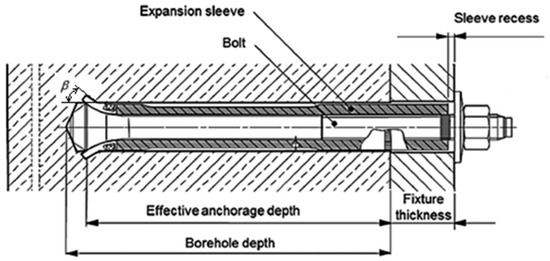
Figure 1.
Example of the design and installation of an undercut anchor system: β–Head angle (undercut in the rock).
Figure 1 presents a typical configuration of an undercut anchor system, specifically a commercially available design produced by HILTI. A key area of research interest concerning such anchors is the determination of the maximum safe load that can be applied without causing either pull-out failure or fracture of the anchor shaft. An analysis of catalog data [39,40] showed that the angle of undercut β resulting from the design parameters of HILTI-HDA type anchors is about 15°. Its value depends largely on the precision of the installation [41] and the precision of the hole for the anchor.
Several methods for estimating the load-bearing capacity of undercut anchors—particularly in scenarios involving the failure of the surrounding concrete in the form of a conical breakout—are presented in the literature [42,43,44,45]. Most of these approaches share a common framework, as they typically rely on two principal variables: the effective embedment depth hef and the compressive strength of concrete fcc measured in cubic specimens (in N/mm2) [39,44,45,46].
Other important aspects considered in the study of anchor systems include the shape and extent of the failure zone—commonly referred to as the concrete breakout cone—as well as the phenomenon of interaction between adjacent failure zones [47,48,49]. These factors are critical for the safe and effective spacing of anchors under anticipated service loads. An inadequate understanding of these interactions may lead to overlapping failure cones, resulting in a significant reduction in the overall load-bearing capacity of the anchorage system. Therefore, proper anchor layout planning, taking into account breakout cone geometry and interaction effects, is essential to ensure structural reliability and safety in service conditions [50,51].
Two principal methods are most commonly employed to estimate the design strength of anchor systems with respect to concrete breakout failure: the 45° cone failure method and the Concrete Capacity Design (CCD) method cone at 35° or an adequate prism [48,49,52].
The 45° cone failure approach assumes that a conical failure surface develops in the concrete surrounding the anchor, forming an angle of approximately 45° between the breakout surface and a plane perpendicular to the anchor axis [52]. This method provides a simplified geometric model of the failure mechanism, which is useful for preliminary calculations and conservative design.
The second method, the CCD (Concrete Capacity Design) approach, is based on a similar failure mode but refines the geometry of the failure surface. It assumes that the breakout takes the shape of a four-sided pyramid with an inclination angle of 35° between the failure surface and the concrete member surface [39,53,54]. The CCD method is more widely accepted in modern engineering practice, as it accounts for a broader range of influencing parameters, including embedment depth, concrete strength, and edge distances, and is incorporated into international design standards such as the European Technical Guidelines and ACI codes.
The authors of this study propose a novel application of undercut anchors, namely as a tool in rock fragmentation technologies (in situ rock mass disintegration) in environments where conventional mechanical excavation methods or the use of explosives are prohibited due to regulatory constraints or operational conditions.
The authors’ previous experience shows that in the case of rocks (sandstone) the extent of the failure zone described, among other things, by the value of the angle of the failure cone α and the value of the diameter of the base of this cone measured at the free surface significantly differs from the characteristic values (taken as standard) for concrete. The Concrete Capacity Design (CCD) method approximates that the maximum projected diameter of the breakout cone on the free surface of concrete corresponds to the length of at most three embedment depths (hef). The numerical computations have demonstrated that, for the nominal breakout prism angle of approx. 35° (CCD), the critical spacing for which the anchor group effect occurs is ~4.5 (a cross-section through two anchor axes). On average, the observed spacing values were in the range of 3.6–4.0.
Previous experimental work on the disintegration of intact rock using mechanical anchors clearly indicates that, for this application, undercut anchors are the most suitable solution due to the specific nature of load application [41,55,56]. The rationale for employing undercut anchors in the proposed rock detachment technology lies in the mechanism of stress induction within the rock mass. Specifically, the stresses generated by the applied load are concentrated at the geometric undercut formed by the cutting head, resulting in a localized stress field that facilitates fracturing of the surrounding rock.
This method of inducing rock failure using an anchor can be conceptually compared to the failure mechanism observed in conventional anchorage systems, where pull-out failure occurs through the formation and detachment of a concrete breakout cone.
An example application area of the proposed technology is the excavation of mine workings (Figure 2), where the process involves local rock disintegration by pulling out individual anchors in locations that allow for the effective detachment of rock lumps. Tests of the proposed technology under industrial conditions are described in [57,58,59].
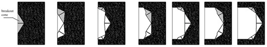
Figure 2.
Example of using the proposed technology for local rock detachment in an excavation site.
In order to gain a closer understanding of the phenomenon of the effect of the interaction of successive detachments in such a proposed technology, the phenomenon was analyzed numerically and experimentally. For particular rock types, a significant correlation was found between the structural parameters of the head, the strength parameters of the rock, and the depth of the hef anchorage [33,46,51,60,61].
Table 1 summarizes the number of successful detachment tests performed for rock samples collected from four mining locations. A total of 115 tests were conducted across the Zalas, Braciszów, Guido, and Brenna mines. The dataset provides the experimental basis for subsequent mechanical analysis and interpretation of rock behavior under load. Field studies were carried out at several rock extraction sites [50]. The number of detachment experiments conducted is summarized in Table 1.

Table 1.
Number of conducted, successful detachment tests.
Table 2 presents the basic mechanical and strength parameters of rocks collected from four different mining sites in Poland. The data include uniaxial compressive strength fc, tensile strength ft, the ratio of compressive to tensile strength (k = fc/ft), internal friction angle (φ), and cohesion (c). Additionally, the rock type and a brief geological description of each sample are provided. These parameters are essential for characterizing the mechanical behavior of the rock masses and assessing their suitability for engineering applications. Mechanical parameters of the studied rocks are illustrated in Table 2 [50].
Table 2.
Mechanical parameters of the studied rocks.
The use of conventional undercut anchors, however, poses significant operational challenges, primarily due to the necessity of employing specialized extraction equipment. Such equipment is typically heavy, bulky, and requires substantial working space for proper handling and maneuvering. As a result of a series of experimental studies, modifications to the anchor design have been proposed [34,50], which also led to a fundamental change in the mechanism of load transfer from the anchor to the surrounding rock mass.
As previously mentioned, one of the primary objectives of the authors is to determine the extent and parameters of the failure zone within a given rock mass, depending on the geometric features of the anchor, the mechanical properties of the rock medium, and the effective embedment depth. The essence of these investigations is illustrated in Figure 3 (based on [40,50]).

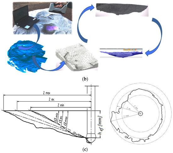
Figure 3.
(a) Components of the experimental setup, measurement signal recording equipment, and recorded parameters: 1—cylinder support; 2—hydraulic cylinder; 3—hand pump set with a pressure gauge; 4—digital recorder; 5—current force acting on the anchor. (b) Identification of the geometric parameters of the failure surface using a Shining 3D handheld 3D laser scanner. (c) Characteristic parameters of the failure surface: hef—effective anchorage depth; α—breakout cone angle; Z—extent of detachment measured on the free surface of the rock medium.
Considering the limitations of the rock detachment method based on pulling out an anchor installed in accordance with standard anchoring procedures used for concrete, an alternative detachment process was carried out using a modified HDP-A type anchor. The modification involved detaching rock fragments by expanding the elements of the anchor near the bottom of the borehole, achieved by enabling the anchor’s drive screw to thread into a conical head (e.g., [50]). During the detachment process, the torque applied to the drive screw was recorded. Based on the calibration of the measurement system, it was possible to determine the equivalent detachment force—analogous to the pull-out force used in conventional anchor-based detachment technology. The essence of this method is illustrated in Figure 4.
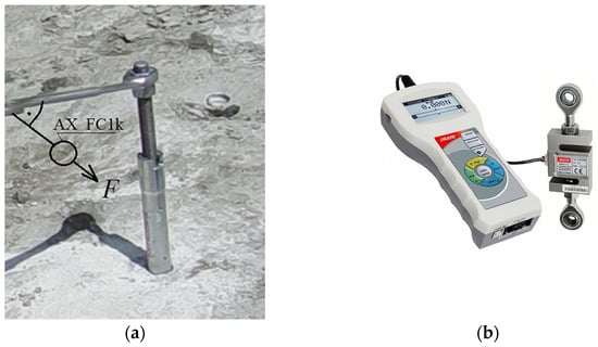
Figure 4.
The application of the installation torque (a) to the anchor’s threaded bolt (as in position 3, Figure 1) that led to the breakout prism detachment; F—force required to turn the threaded bolt in the anchor; (b) electronic force gauge with an external sensor (AX_FC1k).
Instead of relying on axial pull-out forces to detach a rock fragment—through extraction of the embedded anchor—a novel approach has been developed that utilizes radial expansion. In this method, the destructive force is applied by expanding the anchor components near the bottom of the borehole during the rotation of a central drive screw. This expansion induces high local stresses within the rock material, promoting controlled fracturing and detachment without requiring the full extraction of the anchor. One of the proposed solutions involving this modified detachment technology and anchor design is illustrated in Figure 5.
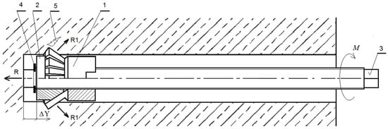
Figure 5.
Modified anchor design for rock mass detachment: 1—undercutting element of the anchor head; 2—conical expansion element; 3—drive screw (anchor core); 4—setting ring; 5—induced crack/fracture in the rock mass; R—reaction force of the drive screw acting on the borehole bottom; R1—reaction force of the anchor head acting on the rock in the undercut zone; M—applied torque on the drive screw; ΔY—incremental (axial) displacement.
An anchor equipped with an undercutting head (1), an expansion element (2), and a drive screw (3), when pre-installed in a borehole drilled into the rock mass, enables localized fracturing of the rock material near the borehole base (Figure 5) [62]. The cylindrical end of the drive screw is in direct contact with the bottom of the hole. As rotational motion is applied to the drive screw using a dedicated drive system, and the anchor head assembly is gradually displaced along the anchor’s axis (with an incremental axial displacement denoted as ΔY in Figure 5, representing the imposed movement of components).
This displacement induces progressive deformation of the surrounding rock and a corresponding increase in stress within the zone of influence around the undercutting head. Ultimately, this results in the porphyry initiation and propagation of a failure zone within the rock mass, typically forming a geometry resembling a breakout cone.
Research efforts aimed at automating the detachment process have led to further modifications of the anchor design, as illustrated in Figure 6. The new detachment anchor design, intended to induce material rupture near the borehole bottom via radial expansion, is characterized by the geometric parameters shown in Figure 6 [54]. In order to enable comparisons, an important element of the conducted tests was to maintain a comparable value of the undercut angle of the medium β (the angle of the anchor head after spreading in the hole) for typical HILTI-type anchors and the proposed anchor design (Figure 5 and Figure 6) because it is important for the propagation of failure [56,60], as well as the formation of the pullout force. Hence, an angle value of β =13.3° was finally used in the anchor design used in the industrial research (Figure 6 [54]). Based on previous experimental investigations and numerical analyses conducted on the first prototype version [55], it was determined that the optimal embedment depth for the proposed detachment method is hef = 70 mm. This value was selected taking into account several critical factors: the extent of the induced fracture zone, the mass of the detached rock fragments, the magnitude of the force (torque) required for successful detachment, and the practical feasibility of manipulating the dislodged rock within the confined space of an excavation, particularly in scenarios such as rescue operations.
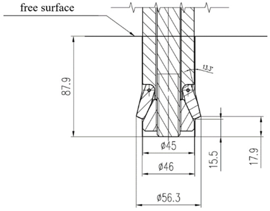
Figure 6.
Characteristic dimensions of the proposed anchor design, developed based on data from ITG KOMAG.
This type of anchor is installed into a pre-drilled borehole with a specially prepared undercut to accommodate the anchor head.
The nominal dimensions of the borehole in the rock (Figure 7), in which the anchor is expanded to its working position, are determined by the characteristic dimensions of the anchor head in its fully expanded state, corresponding to the mounting configuration shown in Figure 4. The borehole (Figure 7) is prepared in advance using a dedicated drill bit and an undercutting tool designed to produce the required borehole profile [62].
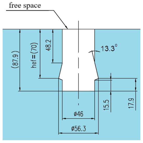
Figure 7.
Nominal dimensions of the installation borehole for the newly designed anchor, developed based on data from ITG KOMAG.
The objective of the numerical simulations, conducted using the Finite Element Method (FEM), was to investigate the mechanism of failure cone formation in the rock mass—specifically its extent and the shape of the fracture trajectories—under the action of a next-generation prototype undercut anchor. The study also aimed to evaluate the applicability of existing analytical models developed for conventional breakout cones formed during the pull-out of traditional undercut anchors. The analyzed process ultimately results in the detachment of rock fragments with a defined volume.
2. Materials and Methods
2.1. Assumptions Adopted in the Model
For simulation purposes, the mechanical parameters characterizing the rock were assumed to be comparable to those measured in field detachment tests [34,50], in which prototypes of the drive unit and the anchor itself were tested under real geological conditions.
The rock material was defined in the model as a linear, elastic, and isotropic solid, with the following mechanical properties:
Young’s modulus: 14,275 MPa;
Poisson’s ratio: 0.247.
The adopted mechanical parameters correspond to gray sandstone collected from the Brenna mine, which was subjected to both field testing and laboratory characterization (Table 2). This specific rock type is characterized by a layered but relatively homogeneous structure with a stratification thickness of 0.7–1.0 m, which did not influence the detachment pattern or extent (Figure 9d in [63]).
The choice of an isotropic, linear elastic model for the rock was a deliberate simplification aimed at isolating and analyzing the influence of the anchor geometry and loading scheme on failure development. While it is recognized that natural rocks often exhibit anisotropy, heterogeneity, and pre-existing discontinuities, the adopted approach is justified by the nature of the tested gray sandstone, which exhibited a homogeneous structure and brittle behavior within the scale of the observed detachment zone. Field experiments confirmed a consistent and repeatable fracture pattern, which supports the use of a simplified material model in the early stage of numerical development. Nonetheless, future work will incorporate more advanced constitutive models to address anisotropy, inhomogeneities, and the presence of bedding planes or joints.
Numerical simulations were conducted using ABAQUS v.2022 (ABAQUS, Version 2022, Dassault Systèmes Simulia Corp., Providence, RI, USA), incorporating the Extended Finite Element Method (XFEM). A brittle fracture criterion was applied, assuming that the onset of material failure is governed by the value of the maximum principal tensile stress. Crack propagation was defined to occur perpendicularly to the direction of the maximum tensile stress. The evolution of damage was controlled by the fracture energy required to extend the crack.
The rock strength parameters used in the numerical simulations are within the range of results obtained from field tests as well as strength tests described in detail by scientific team members [50,56,57,61,63,64,65].
Accordingly, in ABAQUS, the following damage model was implemented:
- Damage initiation criterion: Max Principal Stress;
- Crack growth direction: perpendicular to the maximum principal tensile stress;
- Damage evolution: energy-based fracture propagation.
The critical tensile stress (failure threshold) was set to ft = 7.74 MPa, and the fracture energy Gf was defined as 0.17 N/m, using a linear softening model. A stabilization coefficient of 1 × 10⁻⁶ was applied to ensure numerical convergence in the XFEM algorithm.
The steel used for the anchor components was also modeled as a linear, elastic, and isotropic material, with deformation remaining within the elastic range. The mechanical properties of the steel were defined as follows:
Young’s modulus: 210,000 MPa;
Poisson’s ratio: 0.3.
These parameters ensured accurate representation of the elastic behavior of the steel anchor elements while focusing the fracture simulation on the surrounding rock mass.
In the case of gray sandstone, this is a good approximation, since in the course of field studies [50] there was an unambiguously defined zone of destruction characteristic of brittle materials, with an unambiguously defined course of fracture accompanying the detachment of lumps of rock in the form of a pseudo-cone of destruction (through the classic tearing of the material), which was widely described by the authors [61]. In other media, the image of destruction changed [56,66], but the fracture mechanism itself did not differ from that observed in gray sandstone (ignoring the influence of disturbances in the structure of the material or its cracks).
Although the use of a linear elastic and isotropic model may be regarded as a simplification, it reflects the actual behavior of the studied gray sandstone under field conditions. Experimental investigations at the Brenna site [50,61] revealed a distinctly defined and repeatable failure zone typical of brittle materials, with a consistent pseudo-conical fracture trajectory initiated at the undercut region and propagating toward the free surface. This behavior is indicative of a material that fails predominantly in tension and supports the use of a linear approximation in the early phase of modeling. In simulations involving other lithologies [66], variations in the damage morphology were observed; however, the underlying fracture mechanism remained consistent, further justifying the adopted material simplification. Future work will address this limitation by implementing nonlinear and anisotropic constitutive laws to improve model fidelity.
2.2. Model Geometry, Finite Element Mesh, and Boundary Conditions
An axisymmetric, two-dimensional (2D) model was adopted to represent the interaction between the anchor and the rock mass, as illustrated in Figure 8. Based on previous experimental observations [50], the extent of the failure zone at the rock’s free surface was assumed to reach approximately 3hef, where hef denotes the effective embedment depth of the anchor.
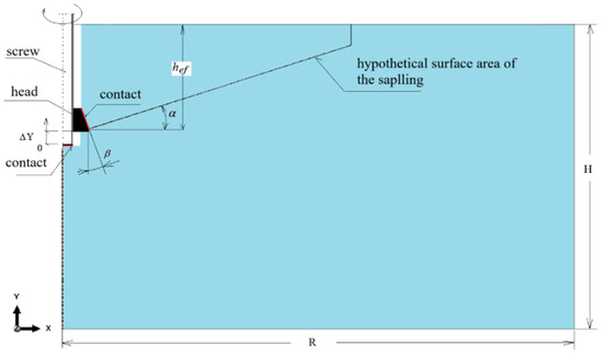
Figure 8.
Axisymmetric model of the detachment anchor acting on the rock mass: α—angle of the breakout cone; β—undercut angle of the rock (anchor head geometry); ΔY—imposed displacement of the anchor components along the Y-axis of the adopted coordinate system.
Using this assumption, the angle of the potential breakout cone was estimated to be α = 20°, corresponding to the trajectory of the hypothetical fracture surface [33].
The selection of α = 20° was not arbitrary but was based on an integrative approach combining field evidence and results of prior numerical simulations. This angle was used as an auxiliary parameter to define the local mesh refinement zone in anticipation of the likely crack path. According to existing standards, a cone angle of approximately 35° is assumed for concrete breakout [39]. However, in the case of natural rocks, our field investigations demonstrated failure cone angles ranging from 13 to 17° in gray sandstone to approximately 25° in porphyry [50,64]. Additionally, 3D FEM simulations conducted in earlier studies showed values between 27° and 29°, depending on the lithology and anchor geometry [46]. In this study, the value α = 20° was selected as a representative average based on these findings. It provided satisfactory agreement between expected crack propagation zones and numerical predictions, especially in defining regions of high mesh density near the failure trajectory.
This estimated failure geometry was explicitly considered in the model to ensure increased finite element mesh refinement in the region of expected crack propagation. By concentrating the mesh in this critical zone, the accuracy of stress distribution analysis and fracture simulation was significantly improved, allowing for detailed observation of damage evolution under the applied load.
The interaction between the tested anchor and the rock mass exhibits an analogy to a linear screw-driven mechanism. The rotational motion of the drive screw around its own axis is transformed into a forced linear displacement of the conical undercutting head along the axis of symmetry of the model (i.e., the screw’s rotational axis). This motion results in a gradual increase in the parameter ΔY, which represents the distance between the tip of the drive screw and the base of the conical cutting head, as illustrated in Figure 8.
Based on the results of field investigations [50], the analyzed domain of the rock mass in the model was defined as a rectangular area with the dimensions R = 500 mm (horizontal) and H = 300 mm (vertical), as shown in Figure 9. The borehole for the anchor is located along the axis of rotation of the model and was modeled with dimensions corresponding to those presented in the referenced figure.
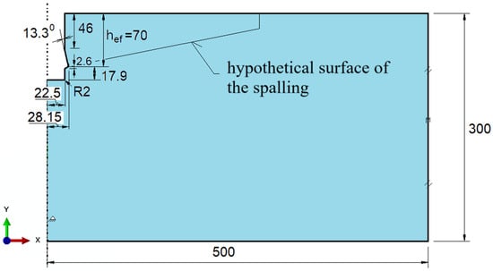
Figure 9.
Geometry of the rock mass model with an undercut borehole for anchor installation.
Using the finite element library available in the ABAQUS software (ABAQUS, Version 2022, Dassault Systèmes Simulia Corp., Providence, RI, USA), the simulation of kinematic loading in the analysis of anchor–rock interaction was implemented through the application of a “connector displacement” element, as illustrated in Figure 10. This element type enables the imposition of prescribed relative motion—specifically, axial displacement—between designated reference points, effectively replicating the linear movement of the anchor head induced by the rotational actuation of the drive screw.
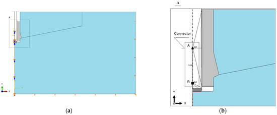
Figure 10.
Boundary constraints of the model (a); modeling of the connection between the anchor head and the drive screw using an axial connector (b). Representation of the movable linkage between anchor components in ABAQUS: A and B—nodes of the linear connector.
This type of connector element includes two nodes (A and B, see Figure 10) whose relative distance can be prescribed and controlled during the simulation. This configuration allows for relative displacement between the two selected nodes of the model exclusively along a predefined axis—in this case, the Y-axis (as shown in Figure 10b)—while rotational degrees of freedom are restricted.
By associating at least two points from each of the relevant components of the anchor model (i.e., the tip of the drive screw and the conical anchor head) with the respective nodes of the connector, it becomes possible to simulate the progressive change in distance between the front face of the anchor head and the end of the screw along the screw axis (the axis of symmetry of the model), as illustrated in Figure 10b.
This procedure effectively enables the implementation of kinematic loading in the finite element model through the use of the defined axial connector. A total connector elongation of ΔY = 10 mm was assumed, in accordance with Figure 8. The elongation was applied iteratively, beginning with an initial incremental step of 0.01 mm, which was subsequently increased until the maximum value was reached while maintaining the numerical convergence of the solution.
In the region where the tip of the drive screw contacts the borehole bottom, as well as in the interaction zone between the conical head and the rock, frictional contact was defined using the “Penalty contact” formulation available in ABAQUS. The coefficient of friction (μ) for the steel–rock interface was set to 0.2, representing an average value typically adopted in this type of simulation.
The boundary conditions applied to the model’s external nodes are illustrated in Figure 10a, where U denotes translational degrees of freedom and UR denotes rotational degrees of freedom. The constraints were defined as follows:
Right edge: U1 = 0, allowing displacement only along the Y-axis (vertical direction);
Bottom edge: U2 = 0, allowing displacement only along the X-axis (horizontal direction);
Left edge of the rock domain, left edge of the screw, and connector nodes: U1 = U3 = UR2 = 0, permitting linear displacement only along the Y-axis, enforcing axisymmetry with respect to the model’s central axis.
The model was discretized using 4-node axisymmetric finite elements of type CAX4R (continuum, axisymmetric, 4-node, reduced integration), generating the finite element mesh shown in Figure 11. This meshing strategy ensured an efficient balance between computational cost and the accuracy required for stress concentration and fracture prediction in the critical zones.
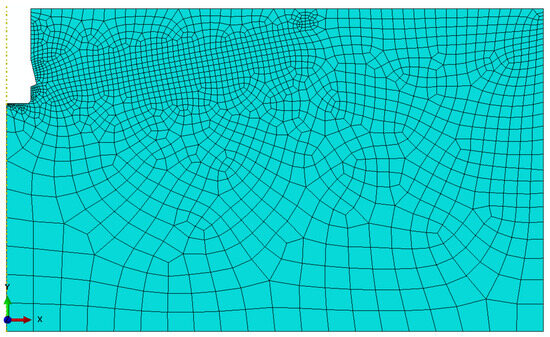
Figure 11.
Finite element mesh of the rock mass model with an undercut borehole.
In critical regions of the model, a non-uniform mesh density was applied by using the automatic mesh generator available in ABAQUS, with manually assigned element seed sizes in selected zones. As a result, the global element size (edge length) was set to 25 mm, while local mesh refinement was implemented in regions of expected high stress gradients and contact interactions as follows:
- In the contact area between the conical anchor head and the rock, the element size was reduced to 2 mm;
- In the contact zone between the screw tip and the borehole bottom, a finer mesh was used with element sizes ranging from 0.4 mm to 1 mm;
- Along the predicted crack propagation path, the element size was refined to 5 mm to enhance the resolution of fracture development;
- Along the upper edge of the rock mass, the element size varied between 3 mm and 10 mm, depending on the specific subregion of the rock domain.
This meshing strategy ensured a balance between computational efficiency and the required resolution in zones where mechanical interaction, stress concentration, and potential crack initiation were anticipated.
Although a graphical representation of mesh sensitivity was not included in the present manuscript, it is important to emphasize that a detailed mesh convergence study was conducted in previous works by the authors [33,55,60,66], where the influence of element size, local refinement strategies, and XFEM-based crack tracking accuracy was extensively analyzed. The adopted mesh parameters and refinement strategy used in this study were based on the optimal configurations established in those earlier publications. Furthermore, due to the use of the XFEM algorithm, which is known for its robustness against mesh dependency effects in fracture problems, the influence of global mesh density on the overall crack trajectory was found to be negligible once a critical refinement threshold was achieved [67,68,69]. Therefore, to avoid duplication of previously published data and due to space constraints, mesh sensitivity analysis was not presented graphically in this article.
The findings reported in prior studies conducted by the authors [33,55,60,66] have repeatedly confirmed that, for both conventional and modified anchor geometries, the selected meshing strategy ensures the adequate resolution of stress fields and accurate crack trajectory prediction within the XFEM framework.
The boundary conditions imposed on the model were designed to replicate realistic constraints present in field applications while also ensuring numerical stability and symmetry. The left edge of the model, which represents the axis of symmetry, was fully constrained in the radial (horizontal) direction (U1 = 0) and rotational degrees of freedom (UR2 = 0), allowing displacement only along the vertical axis. The bottom edge of the domain was restrained vertically (U2 = 0) to simulate the presence of a supporting rock mass below the anchor. The right vertical edge was constrained horizontally (U1 = 0), simulating confinement by the surrounding rock and preventing artificial lateral expansion. These constraints reflect a semi-infinite domain approximation commonly used in axisymmetric fracture modeling and ensure that artificial boundary effects do not interfere with the stress distribution and crack propagation around the anchor head.
The extensive experience gained through these investigations justifies the use of previously validated mesh configurations in the present analysis. Consequently, the current study adopted the optimal mesh structure established earlier, with no additional graphical documentation of mesh sensitivity included herein, as it would not contribute new insights. This approach is further supported by numerous reports in the literature [70,71,72], which emphasize that when XFEM is employed, the influence of global mesh size on the quality of fracture predictions becomes significantly reduced, provided that localized refinement is properly applied in critical regions [73].
For the rock mass model, the total number of generated nodes was 1285, and the number of elements was 1195. The radial clearance between the cylindrical surfaces of the anchor and the borehole was set to 0.5 mm, representing one of the analyzed configuration variants.
For the anchor body, the mesh included 338 nodes and 294 elements, of which 287 were linear quadrilateral elements of type CAX4R and 7 were linear triangular elements of type CAX3.
For the drive screw, the mesh consisted of 103 nodes and 85 elements, including 83 linear quadrilateral elements (CAX4R) and 2 linear triangular elements (CAX3).
3. Results and Discussion
In recent years, the growing complexity of engineering problems in geomechanics and material science has intensified the need for advanced computational methods capable of capturing intricate mechanical behaviors of heterogeneous media such as composite materials, rocks, or cementitious systems. In this context, numerical approaches—including the Finite Element Method (FEM) [74,75,76], Boundary Element Method (BEM) [77,78,79], and various analytical formulations [80,81]—have proven invaluable for modeling stress distribution, crack initiation, and failure propagation in cases where experimental investigations are constrained by limited access to representative samples, high testing costs, or safety concerns. These methods enable the detailed exploration of failure mechanisms and material responses under controlled boundary conditions, often exceeding what is feasible in laboratory settings. Furthermore, the integration of machine learning algorithms with traditional computational techniques offers new avenues for pattern recognition, inverse problem solving, and model calibration [82,83,84,85]. Particularly in scenarios involving limited experimental data, supervised learning or surrogate modeling can enhance the predictive accuracy of numerical simulations. The synergy between numerical modeling and artificial intelligence thus provides a robust framework for optimizing design, improving failure predictions, and supporting decision-making in engineering applications involving complex material systems [86,87,88,89,90,91].
The study revealed a predominant tendency for material cracking to occur beneath the tip of the driving screw (Figure 12 and Figure 13), which differs from failure patterns observed in pull-out anchor models or those related to installation anchor systems, where crack initiation typically occurs at the notch corner created by a conical undercutting head [60].

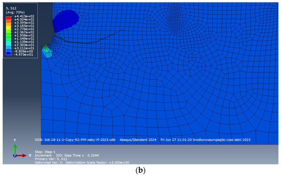
Figure 12.
(a) Distribution of maximum principal stress σmax and bimodal crack development under the action of the detachment/expansion anchor: 1—primary crack, which diminishes during the progressive displacement of the anchor along the OY axis (as imposed by the kinematic loading); 2—secondary crack, responsible for the final detachment of the breakout “cone” of the rock mass; (b) stress σ12 distribution.
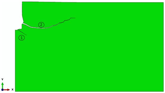
Figure 13.
Bimodal crack development under the action of the detachment anchor: 1—diminishing primary crack; 2—secondary crack leading to the detachment of a larger rock fragment.
The results also confirmed a characteristic two-stage evolution of the detachment crack, consistent with findings reported in earlier studies [61]. In the first stage, the fracture propagates deep into the rock mass along a parabolic trajectory, initiated under a negative or zero initial penetration angle (α), as described in detail in [55,61]. In the second stage, a deflection in the crack trajectory occurs, and the fracture begins to propagate asymptotically toward the free surface of the rock. This behavior continues until the eventual breakout of the detached rock fragment in the final phase of the process.
It should be noted that minor deviations from the expected trajectory may result from limitations in the crack direction algorithm implemented in ABAQUS, which were also documented in previous studies [41,56,63].
Figure 12 and Figure 13 demonstrate a strong correspondence between the stress distribution in the anchor–rock interaction zone and the shape and trajectory of the propagating fracture, as compared to the results obtained in numerical simulations of the initial prototype of the detachment anchor [41,55], as well as earlier studies involving the use of undercut anchors [61,92,93], in which the anchor was extracted using specialized equipment. These findings are also consistent with current in situ experimental results involving the newly proposed anchor design.
The numerical results obtained in this study reveal notable discrepancies when compared to conventional failure models such as the Concrete Capacity Design (CCD) method or the 45° cone model. Most significantly, the two-stage crack propagation process, characterized by initiation beneath the tip of the drive screw and subsequent progression toward the free surface, deviates from the uniform failure trajectories assumed in traditional models.
This divergence underscores the necessity of extending existing theoretical frameworks to incorporate alternative fracture propagation mechanisms, especially in cases involving non-standard anchor geometries and atypical loading modes. Such developments are essential for the effective design and optimization of rock excavation systems, particularly under mining conditions where conventional assumptions may no longer hold.
A major limitation of the technology based on the extraction of undercut anchors was the bulky size of the equipment required to pull out the anchor along with the detached rock fragment. This significantly restricted the applicability of the proposed method in underground mining, particularly due to spatial constraints in confined working environments. In contrast, the newly proposed anchor design for rock fracturing does not suffer from such limitations.
The results of the conducted analyses indicate high potential for the proposed solution in engineering applications, especially in scenarios where the use of explosives is prohibited or where space is limited—such as mine rescue operations, microtunneling, or the restoration of rock-cut historical structures. The compact design of the anchor, which does not require heavy activation equipment, offers an effective alternative to traditional mechanical excavation technologies.
Furthermore, the system may also be applicable in military and civil operations involving controlled rock mass fragmentation, where precision, safety, and portability are of critical importance.
The presented numerical analyses revealed a high sensitivity of the applied rock–anchor interaction model to several key factors, including:
- The mesh density in critical regions of the model;
- The element size (edge length of finite elements);
- The radial clearance between the cylindrical borehole wall and the cylindrical surface of the anchor.
These parameters were found to have a particularly strong influence on the location of crack initiation under the action of the anchor head, as illustrated in Figure 12 and Figure 13. Small variations in these factors resulted in noticeable changes in the stress distribution and fracture trajectory, emphasizing the need for precise meshing and geometrical definitions in future modeling efforts.
Although the present model employed typical mechanical parameters for sandstone, it is important to emphasize that the physical and mechanical properties of natural rocks can exhibit significant variability, resulting from factors such as porosity, stratification, and moisture content.
Therefore, it is advisable to conduct a series of parametric studies to evaluate the influence of key factors—such as tensile strength (ft), Young’s modulus (E), and fracture energy (Gf)—on the shape and extent of the failure zone.
Such analyses would contribute to the development of a more robust and generalized predictive model, capable of accounting for the variability of geotechnical conditions and enhancing the reliability of anchor-based rock detachment technologies across diverse geological environments.
The use of a “penalty” contact model with an assumed friction coefficient μ = 0.2 had a significant impact on the localization of stress concentration zones near the tip of the drive screw and the anchor head. This parameter plays a critical role in determining the crack initiation trajectory and can lead to substantial variations in the resulting failure pattern.
For future studies, it is recommended to consider the implementation of alternative contact formulations, such as “hard contact” models or pressure-dependent elastic contact conditions. These approaches could enable a more accurate representation of the real interaction mechanisms between the anchor and the surrounding rock mass, thereby improving the predictive accuracy of numerical simulations.
The study results indicate that, as shown in Figure 13, there is a possibility that during the initial phase of anchor expansion, a primary crack (1) may be initiated beneath the tip of the drive screw as a result of exceeding Hertzian contact stresses. This primary fracture eventually ceases to propagate. Subsequently, a secondary crack (2) emerges at the corner of the conical undercut in the rock, which then progressively propagates toward the free surface of the rock mass.
This observed sequence highlights the complex, staged nature of the fracture mechanism, driven by the specific stress distribution induced by the geometry and loading characteristics of the expanding anchor system.
Model Validation
In order not to duplicate information in a whole series of publications on the new stripping technology, the field research is described in the article only insofar as it relates to the issues raised in the FEM simulation. A detailed description of the entire field research is presented, for example, in [50,63]. This way of presenting information was based on the desire not to duplicate previously shared content regarding the measurement system.
During the prototype development and testing phase of the anchor (1), which was manually driven, a torque multiplier (2) was employed, as shown in Figure 14 (in the final design, the automation of the anchoring process and detachment using the drilling machine drive is planned). To install the anchor into the rock mass, a specially designed drill bit was used to create a borehole with an undercut corresponding to the expandable anchor head. The torque manually applied via a wrench, the torque multiplier, and the internal mechanism of the anchor was transformed into a radial expansion force acting on the anchor components near the bottom of the borehole.
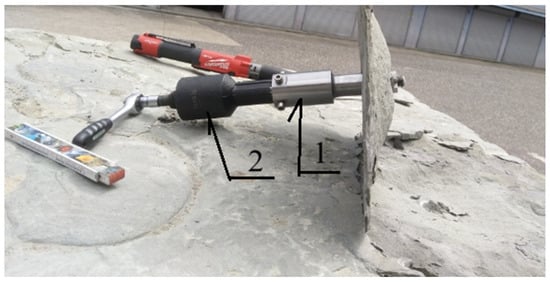
Figure 14.
Typical shape of the detached rock fragment obtained using the tested detachment anchor design. Detachment achieved using an anchor assembly (1) and torque multiplier (2).
As the applied torque increased, so did the bearing dimensions of the contact points between the end of the drive screw and the conical head against the rock (as illustrated in Figure 10b), which in turn induced rock deformations. Ultimately, this led to the initiation and propagation of a crack, resulting in the detachment of a rock fragment in a shape resembling a cone. Experimental and field investigations revealed that the dominant failure mode involves detachment initiated at the corner of the conical undercut in the rock, with the resulting fracture following a deflected trajectory, as described in the preceding sections. This characteristic crack path, featuring an initial steep propagation followed by a gradual redirection toward the rock’s free surface, is illustrated in Figure 14.
In the experimental studies, an alternative form of detachment was also observed, characterized by fracture initiation beneath the tip of the drive screw, as illustrated in Figure 15. However, in this case, the location of the initiation point may have been significantly influenced by factors such as stratification (bedding planes) within the sandstone or the proximity of the borehole to the sample’s edge.
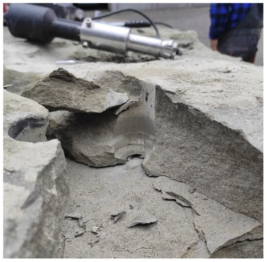
Figure 15.
Experimental tests—detachment of the rock mass with initiation of separation in the zone influenced by the end of the anchor’s driving bolt.
These factors introduce uncertainty regarding the fracture mechanism, and thus, further investigations are necessary to clarify their role and influence. Future research should include a systematic analysis of rock heterogeneity, sample geometry, and borehole positioning, to better understand their impact on detachment behavior.
In response to the inherent variability of mechanical properties among different rock types, the authors have extended their research beyond gray sandstone. A comparative study involving porphyry (Zalas) and several varieties of sandstone (Braciszów, Guido, Brenna) was previously conducted and is published in [34,61]. These materials exhibited significant variation in uniaxial compressive strength, tensile strength, internal friction angle, and cohesion (as shown in Table 2). The analyses revealed that while the general failure mechanism induced by undercut anchors remains consistent—primarily tensile-driven fracture initiated near the anchor head—the extent and geometry of the breakout zone vary substantially with lithology. For instance, the observed breakout cone angles ranged from 13–17° in weak sandstone to up to 25° in porphyry, underscoring the need to adjust simulation parameters according to lithological context. The findings from [34,61] reinforce the validity of the presented FEM model and demonstrate its applicability across different rock types. The role of the friction coefficient between the anchor head and the rock medium is crucial in shaping the extent and geometry of the failure zone. As shown in our previous study [60], increasing the value of the Coulomb friction coefficient results in a significant reduction in the range of the failure cone measured on the rock’s free surface. A higher friction coefficient leads to an increased initial fracture angle (α0), thus narrowing the failure zone and modifying the trajectory of crack propagation. These effects were also observed in complementary analyses using different anchor designs [14], including XFEM-based simulations of breakout anchors subjected to radial expansion. In the present study, a friction coefficient μ = 0.2 was selected based on averaged literature data and experimental consistency for dry sandstone contact conditions. However, additional parametric studies (e.g., μ = 0.0–1.5) presented in [60,93] confirmed the critical impact of this parameter on the initiation and evolution of rock damage.
4. Summary and Conclusions
The numerical modeling approach based on the use of a linear connector element should be regarded as a milestone in advancing the understanding of rock failure mechanisms under the action of a detachment (fracturing) anchor. Previous treatments of this subject, largely derived from studies on installation anchors embedded in materials such as concrete, tended to oversimplify the problem and did not allow for a comprehensive description of the processes governing the initiation and propagation of failure zones in rock masses.
The widespread conceptualization of the failure region as a so-called breakout cone represents a significant simplification. While this model is undoubtedly useful in the design and standardization of anchorage systems in concrete structures, it does not permit the optimization of the rock detachment process, particularly in configurations involving interaction between adjacent failure zones [46].
The conducted numerical analyses confirmed the feasibility of the proposed detachment technology, its effectiveness, and its potential applicability in selected areas of engineering practice. Moreover, the numerical findings are consistent with the results obtained from experimental tests carried out using a prototype detachment anchor, especially in terms of the shape and extent of the resulting fracture zone.
A comprehensive parametric analysis is required to systematically compare the results obtained for various material and geometric configurations. Previous studies focused primarily on validating the fracture model for a selected rock type and a specific anchor design. However, preliminary investigations [51,56] have examined the influence of parameters such as tensile strength (ft), Young’s modulus (E), fracture energy (Gf), and anchor head angle (β) on failure propagation and breakout geometry. In subsequent phases, a structured comparative analysis will be conducted, encompassing different loading scenarios and geotechnical conditions, with the use of standardized indicators and visualization techniques. These analyses will be extended to include a broader range of lithological conditions and modified anchor geometries, enabling the assessment of model sensitivity and applicability under real-world conditions.
5. Model Limitations and Future Research Perspectives
Despite the satisfactory results obtained from the simulations, it is important to acknowledge the limitations of the adopted model. In particular, the assumption of linear elasticity and material isotropy does not fully capture the complex behavior of rock under localized stress conditions.
Given the lack of basic knowledge of the proposed technology and the use of knowledge in the field of fastening technology, the presented results of both field and numerical research should be regarded as a preliminary stage of research to identify gaps in existing knowledge. In subsequent stages, the research will already be significantly expanded and, of course, conducted in accordance with the developed research plan.
The authors have so far carried out exploratory studies of the trends of changes in the propagation/range of the failure zone depending on influential factors such as effective anchorage depth, rock strength parameters, fracture energy, coefficient of friction of the rock against the anchor head, or the value of the anchor head angle. These topics have been presented in a series of publications in [50,57,61,63,64,65], among others.
The assumption of linear elasticity and isotropy of rocks is a deliberate decision by the authors due to the fact that the fundamental knowledge in the field of anchoring (to which the authors refer) concerns concrete materials with controlled properties, including high structural homogeneity achieved during the pouring process. For such materials, it is highly probable—according to accepted standards—that a simplified failure model (failure cone) can be created, anchor capacities can be predicted, etc. In other cases, such as the introduction of concrete reinforcement or fiber reinforcement [94], an individual approach is required, including specific material models [95]. Similarly, in the case of media with heterogeneous structures [96,97], the analysis requires the application of, for example, homogenization theory [96,98] or complex models accounting for stratification, fracturing of the rock mass, or all these factors simultaneously [99,100]. The members of the research team have conducted a number of such analyses in the context of other problems within the discussed field [101,102], but due to the specific aspects addressed in this study, the analysis was limited to the presented scope.
Future work should consider the implementation of nonlinear material models (e.g., elastic–plastic or elastic–brittle behavior), as well as the development of three-dimensional finite element models (FEMs). These enhancements would enable more accurate representation of phenomena such as localized moisture content, pre-existing fractures, and sedimentary anisotropy.
Incorporating such refinements would significantly improve the fidelity of the simulations and the ability to replicate real operating conditions, thereby increasing the reliability of the model for engineering applications.
Author Contributions
Conceptualization, J.J. and R.K.; methodology, A.W. and J.J.; software, A.W.; validation, J.J. and R.K.; formal analysis, J.J. and R.K.; investigation, J.J., R.K., and K.J.; resources, J.J., R.K., and K.J.; data curation, A.W. and K.J.; writing—original draft preparation, J.J. and R.K.; writing—review and editing, J.J. and R.K.; visualization, J.J. and K.J.; supervision, J.J., K.J. and R.K.; project administration, J.J. and R.K.; funding acquisition, J.J. and R.K. All authors have read and agreed to the published version of the manuscript.
Funding
This project was financed by the Polish National Center for Research and Development under the TANGO IV program under the title “Technology for unconventional falling off the rock fragments”, project number: TANGO-IV-A/0058/2019.
Institutional Review Board Statement
Not applicable.
Informed Consent Statement
Not applicable.
Data Availability Statement
The data presented in this study is available from the corresponding author upon request.
Conflicts of Interest
The authors declare no conflicts of interest. The funders had no role in the design of the study; in the collection, analyses, or interpretation of data; in the writing of the manuscript; or in the decision to publish the results.
References
- Kamara, M.E.; Rabbat, B.G. PCA Notes on ACI 318-05 Building Code Requirements for Structural Concrete with Design Applications; Portland Cement Association: Skokie, IL, USA, 2005; ISBN 0-89312-245-9. [Google Scholar]
- ACI Committee 318; Building Code Requirements for Structural Concrete (ACI 318-05) and Commentary (ACI 318R-05). American Concrete Institute: Farmington Hills, MI, USA, 2005; ISBN 0-87031-171-9.
- Nemes, R.; Lublói, É. Application of Anchors under Special Concrete Conditions. Period. Polytech. Civ. Eng. 2011, 55, 73. [Google Scholar] [CrossRef]
- Ren, Y.; Wang, H.; Guan, Z.; Yang, K. Evaluation of the Properties and Applications of FRP Bars and Anchors: A Review. Rev. Adv. Mater. Sci. 2023, 62, 20220287. [Google Scholar] [CrossRef]
- Serrano, A.; Olalla, C. Tensile Resistance of Rock Anchors. Int. J. Rock Mech. Min. Sci. 1999, 36, 449–474. [Google Scholar] [CrossRef]
- Gaudin, C.; Cassidy, M.J.; O’Loughlin, C.D.; Tian, Y.; Wang, D.; Chow, S. Recent Advances in Anchor Design for Floating Structures. Int. J. Offshore Polar Eng. 2017, 27, 44–53. [Google Scholar] [CrossRef]
- Brown, E.T. Rock Engineering Design of Post-Tensioned Anchors for Dams—A Review. J. Rock Mech. Geotech. Eng. 2015, 7, 1–13. [Google Scholar] [CrossRef]
- Bokor, B.; Tóth, M.; Sharma, A. Fasteners in Steel Fiber Reinforced Concrete Subjected to Increased Loading Rates. Fibers 2018, 6, 93. [Google Scholar] [CrossRef]
- Tóth, M.; Bokor, B.; Sharma, A. Befestigungen Im Stahlfaserverstärkten Beton Bei Betonbruch—Stand Der Technik Und Bemessungsansatz/Anchorages in Steel Fiber Reinforced Concrete in the Case of Concrete Breakout Failure—State of the Art and Design Concept. Bauingenieur 2021, 96, 254–265. [Google Scholar] [CrossRef]
- Tóth, M.; Bokor, B.; Sharma, A. Anchorage in Steel Fiber Reinforced Concrete—Concept, Experimental Evidence and Design Recommendations for Concrete Cone and Concrete Edge Breakout Failure Modes. Eng. Struct. 2019, 181, 60–75. [Google Scholar] [CrossRef]
- Bokor, B.; Sharma, A.; Hofmann, J. Experimental Investigations on Concrete Cone Failure of Rectangular and Non-Rectangular Anchor Groups. Eng. Struct. 2019, 188, 202–217. [Google Scholar] [CrossRef]
- Bokor, B.; Sharma, A.; Pregartner, T. An Assessment Method to Ensure Applicability of Concrete Capacity Method for Design of Anchorages: Linear Force Distribution Approach. Struct. Concr. 2023, 24, 7249–7271. [Google Scholar] [CrossRef]
- Zheng, H.; Wu, X.; Jiang, Y.; Wang, G.; Wang, Z. Shear Behavior of Rock Joints Reinforced with Fully-Grouted and Energy-Absorbing Bolts Subjected to Shear Cycles. J. Rock Mech. Geotech. Eng. 2024, S1674775524005766. [Google Scholar] [CrossRef]
- Kraft, R.; Zien, J. Mining Anchor Text for Query Refinement. In Proceedings of the 13th International Conference on World Wide Web, New York, NY, USA, 17–20 May 2004; ACM: New York, NY, USA, 2004; pp. 666–674. [Google Scholar]
- Cao, J.; Zhang, N.; Wang, S.; Qian, D.; Xie, Z. Physical Model Test Study on Support of Super Pre-Stressed Anchor in the Mining Engineering. Eng. Fail. Anal. 2020, 118, 104833. [Google Scholar] [CrossRef]
- Ma, Z.; Chen, C.; Sun, X.; Wu, G.; Liu, P.; Gao, L. Test and Numerical Simulation of Failure Mechanism of Barrel and Wedge Anchorage in Coal Mines. Constr. Build. Mater. 2020, 237, 117647. [Google Scholar] [CrossRef]
- Mahrenholtz, C.; Eligehausen, R. Dynamic Performance of Concrete Undercut Anchors for Nuclear Power Plants. Nucl. Eng. Des. 2013, 265, 1091–1100. [Google Scholar] [CrossRef]
- Kim, N.-K.; Park, J.-S.; Kim, S.-K. Numerical Simulation of Ground Anchors. Comput. Geotech. 2007, 34, 498–507. [Google Scholar] [CrossRef]
- Fangtian, W.; Cun, Z.; Shuaifeng, W.; Xiaogang, Z.; Shenghua, G. Whole Section Anchor–Grouting Reinforcement Technology and Its Application in Underground Roadways with Loose and Fractured Surrounding Rock. Tunn. Undergr. Space Technol. 2016, 51, 133–143. [Google Scholar] [CrossRef]
- Konietzky, H.; Frühwirt, T. Rock Bolting: Characterization and Fluid Transport Simulations of Fractures and Fracture Networks; TU Bergakademie Freiberg, Geotechnical Institute: Freiberg, Germany, 2024.
- Sujatha, E.R.; Sudarsan, J.S.; Nithiyanantham, S. A Review on Sustainable Reinforcing Techniques to Stabilize Slopes against Landslides. Int. J. Environ. Sci. Technol. 2023, 20, 13873–13882. [Google Scholar] [CrossRef]
- Brezzi, L.; Bisson, A.; Pasa, D.; Cola, S. Innovative Passive Reinforcements for the Gradual Stabilization of a Landslide According with the Observational Method. Landslides 2021, 18, 2143–2158. [Google Scholar] [CrossRef]
- Murgia, I.; Giadrossich, F.; Mao, Z.; Cohen, D.; Capra, G.F.; Schwarz, M. Modeling Shallow Landslides and Root Reinforcement: A Review. Ecol. Eng. 2022, 181, 106671. [Google Scholar] [CrossRef]
- Trofymchuk, O.; Kaliukh, I.; Berchun, V. Landslide Stabilization in Building Practice: Methodology and Case Study from Autonomic Republic of Crimea. In Advancing Culture of Living with Landslides; Mikoš, M., Arbanas, Ž., Yin, Y., Sassa, K., Eds.; Springer International Publishing: Cham, Switzerland, 2017; pp. 587–595. ISBN 978-3-319-53486-2. [Google Scholar]
- Knox, G.; Hadjigeorgiou, J. Performance of Conventional and Energy-Absorbing Self-Drilling Hollow Core Rockbolts Under Controlled Laboratory Conditions. Rock Mech. Rock Eng. 2023, 56, 4363–4378. [Google Scholar] [CrossRef]
- Jalali Moghadam, M.; Dastaran, N.; Zad, A. Introducing Expandable Mechanical Plate Anchors for Onshore and Offshore Anchoring. Mar. Georesources Geotechnol. 2022, 40, 329–348. [Google Scholar] [CrossRef]
- Cerfontaine, B.; White, D.; Kwa, K.; Gourvenec, S.; Knappett, J.; Brown, M. Anchor Geotechnics for Floating Offshore Wind: Current Technologies and Future Innovations. Ocean Eng. 2023, 279, 114327. [Google Scholar] [CrossRef]
- Gkournelos, P.D.; Triantafillou, T.C.; Bournas, D.A. Seismic Upgrading of Existing Reinforced Concrete Buildings: A State-of-the-Art Review. Eng. Struct. 2021, 240, 112273. [Google Scholar] [CrossRef]
- Zhong, C.; Christopoulos, C. Self-Centering Seismic-Resistant Structures: Historical Overview and State-of-the-Art. Earthq. Spectra 2022, 38, 1321–1356. [Google Scholar] [CrossRef]
- Cao, X.-Y.; Shen, D.; Feng, D.-C.; Wang, C.-L.; Qu, Z.; Wu, G. Seismic Retrofitting of Existing Frame Buildings through Externally Attached Sub-Structures: State of the Art Review and Future Perspectives. J. Build. Eng. 2022, 57, 104904. [Google Scholar] [CrossRef]
- Zheng, H.; Wu, X.; Jiang, Y.; Wang, G.; Li, B. Insights into Velocity-Dependent Shear Characteristics of Bolted Rock Joints: A Comparative Study of Fully-Grouted and Energy-Absorbing Bolts. Int. J. Rock Mech. Min. Sci. 2024, 183, 105910. [Google Scholar] [CrossRef]
- Wang, Z.; Liao, L.; Guo, S.; Zheng, H.; Wu, X. Numerical Investigation of Bolted Rock Joints under Varying Normal Stress and Joint Roughness Coefficient Conditions. Front. Earth Sci. 2024, 12, 1402708. [Google Scholar] [CrossRef]
- Jonak, J.; Wójcik, A.; Karpiński, R.; Jonak, K. Effect of Undercut Bolt Anchor Depth on Failure Cone Geometry: A Numerical FEM Analysis and Experimental Verification. Materials 2025, 18, 686. [Google Scholar] [CrossRef]
- Wójcik, A.; Jonak, K.; Karpiński, R.; Jonak, J.; Kalita, M.; Prostański, D. Mechanism of Rock Mass Detachment Using Undercutting Anchors: A Numerical Finite Element Method (FEM) Analysis. Materials 2024, 17, 4468. [Google Scholar] [CrossRef]
- Stephansson, O. (Ed.) Rock Bolting: Theory and Application in Mining and Underground Construction: Proceedings of the International Symposium on Rock Bolting, Abisko, 28 August–2 September 1983; Routledge: London, UK, 2020; ISBN 978-1-351-41818-8. [Google Scholar]
- McMillan, R. Empirical Analysis of Brittle Rock Mass Failure in Response to Undercut Advance for Preventive Support Maintenance. Ph.D. Thesis, University of British Columbia, Vancouver, BC, Canada, 2022. [Google Scholar] [CrossRef]
- Zheng, H.; Jiang, Y.; Wu, X.; Zhang, S.; Sugimoto, S. Investigation on Stress Distribution and Prestress Loss Model of Prestressed Anchor Cables Considering Corrosion-Induced Debonding. Rock Mech. Bull. 2025, 4, 100189. [Google Scholar] [CrossRef]
- Wu, X.; Zhao, M.; Ye, Q.; Jiang, Y.; Deng, T.; Zheng, H.; Wang, G.; Guan, Z. A New Deformable Cable for Rock Support in High Stress Tunnel: Steel Pipe Shrinkable Energy-Absorbing Cable. Int. J. Min. Sci. Technol. 2024, 34, 1083–1093. [Google Scholar] [CrossRef]
- Fuchs, W.; Eligehausen, R.; Breen, J.E. Concrete Capacity Design (CCD) Approach for Fastening to Concrete. Struct. J. 1995, 92, 73–94. [Google Scholar] [CrossRef]
- Hilti Anchor Fastening Technology Manual; Version 2023; Hilti: Schaan, Liechtenstein, 2023.
- Jonak, J.; Karpiński, R.; Wójcik, A. Influence of the Undercut Anchor Head Angle on the Propagation of the Failure Zone of the Rock Medium—Part II. Materials 2021, 14, 3880. [Google Scholar] [CrossRef]
- Tan, E.L.; Varsani, H.; Liao, F. Experimental Study on Demountable Steel-Concrete Connectors Subjected to Combined Shear and Tension. Eng. Struct. 2019, 183, 110–123. [Google Scholar] [CrossRef]
- Jonak, J.; Siegmund, M. FEM 3D Analysis of Rock Cone Failure Range during Pull-out of Undercut Anchors. IOP Conf. Ser. Mater. Sci. Eng. 2019, 710, 012046. [Google Scholar] [CrossRef]
- ACI Committee 355; State-of-the-Art Report on Anchorage to Concrete. American Concrete Institute: Detroit, MI, USA, 1991.
- Comite Euro-International Du Beton (CEB), Task Group VI/5. Fastenings to Concrete and Masonry Structures; ThomasTelford Services Ltd.: London, UK, 1994; p. 249. [Google Scholar]
- Jonak, J.; Siegmund, M.; Karpiński, R.; Wójcik, A. Three-Dimensional Finite Element Analysis of the Undercut Anchor Group Effect in Rock Cone Failure. Materials 2020, 13, 1332. [Google Scholar] [CrossRef]
- Farrow, C.B.; Lmed, F.; Richard, E. Klingner Tensile Capacity of Single Anchors in Concrete: Evaluation of Existing Formulas on an LRFD Basis. ACI Struct. J. 1996, 93, 128–137. [Google Scholar] [CrossRef]
- Cook, R.A. Behavior and Design of Ductile Multiple-Anchor Steel-to-Concrete Connections; The University of Texas at Austin: Austin, TX, USA, 1989; ISBN 979-8-206-89520-9. [Google Scholar]
- Ballarini, R.; Yueyue, X. Fracture Mechanics Model of Anchor Group Breakout. J. Eng. Mech. 2017, 143, 04016125. [Google Scholar] [CrossRef]
- Jonak, J.; Karpiński, R.; Siegmund, M.; Machrowska, A.; Prostański, D. Experimental Verification of Standard Recommendations for Estimating the Load-Carrying Capacity of Undercut Anchors in Rock Material. Adv. Sci. Technol. Res. J. 2021, 15, 230–244. [Google Scholar] [CrossRef]
- Jonak, J.; Karpiński, R.; Wójcik, A. Influence of Anchor Depth and Friction Coefficient Between Anchor and Rock on the Trajectory of Rock Masses Detachment. Adv. Sci. Technol. Res. J. 2023, 17, 290–298. [Google Scholar] [CrossRef]
- Bennett, M.S. Prediction of the Shear Cone Geometry Surrounding Headed Anchor Studs; Lehigh University: Bethlehem, PA, USA, 1979. [Google Scholar]
- Fuchs, W.; Eligehausen, R. Das CC-Verfahren Für Die Berechnung Der Betonausbruchlast von Verankerungen. Beton Und Stahlbetonbau 1995, 90, 6–9. [Google Scholar] [CrossRef]
- Michał, S.; Jonak, J.; Prostański, D.; Bałaga, D.; Kalita, M. Głowica Do Niekonwencjonalnego Odspajania Fragmentów Skał 1–26. Available online: https://uprp.gov.pl/sites/default/files/bup/2023/Wynalazki%20i%20wzory%20użytkowe/12_49-52/50/bup50_2023.pdf (accessed on 4 July 2025).
- Jonak, J.; Karpiński, R.; Wójcik, A.; Siegmund, M.; Kalita, M. Determining the Effect of Rock Strength Parameters on the Breakout Area Utilizing the New Design of the Undercut/Breakout Anchor. Materials 2022, 15, 851. [Google Scholar] [CrossRef] [PubMed]
- Jonak, J.; Karpiński, R.; Wójcik, A. Influence of the Undercut Anchor Head Angle on the Propagation of the Failure Zone of the Rock Medium. Materials 2021, 14, 2371. [Google Scholar] [CrossRef]
- Siegmund, M. Selected Technologies for Destruction of Rocks Cohesion by Using Their Tensile Strength Properties. Min. Mach. 2021, 39, 2–16. [Google Scholar] [CrossRef]
- Cebula, D.; Kalita, M.; Prostański, D. Próby Dołowe Technologii Drążenia Tuneli Ratowniczych Metodą Małego Penetratora TP130. Masz. Górnicze 2015, 1, 27–33. [Google Scholar]
- Siegmund, M.; Jonak, J. Analysis of the Results of Preliminary Studies and Determination of Direction of Further Research Work on Technology of Drilling the Rescue Tunnels by the Method of Mechanical Loosening. Cuprum Czas. Nauk.-Tech. Górnictwa Rud 2017, 82, 57–71. [Google Scholar]
- Wójcik, A.; Jonak, J.; Karpiński, R.; Jonak, K.; Prostański, D.; Kaczyński, R. A Numerical Study of the Influence of Cone Angle of the Breakout Anchor Head on the Crack Trajectory of the Medium. Adv. Sci. Technol. Res. J. 2024, 18, 101–112. [Google Scholar] [CrossRef]
- Jonak, J.; Karpiński, R.; Wójcik, A.; Siegmund, M. The Influence of the Physical-Mechanical Parameters of Rock on the Extent of the Initial Failure Zone under the Action of an Undercut Anchor. Materials 2021, 14, 1841. [Google Scholar] [CrossRef]
- Jonak, J. Kotwa Podcinająco-Odspajająca-Nr Zgłoszenia Patentowego A 429560//Biuletyn Urzędu Patentowego: Wynalazki I Wzory Użytkowe. 2019; Nr 25; p. 41. Available online: https://uprp.gov.pl/sites/default/files/bup/2019/Wynalazki%20i%20wzory%20u%C5%BCytkowe/12_25-26/25/bup25_2019.pdf (accessed on 1 May 2025).
- Siegmund, M.; Kalita, M.; Bałaga, D.; Kaczmarczyk, K.; Jonak, J. Testing the Rocks Loosening Process by Undercutting Anchors. Stud. Geotech. Mech. 2020, 42, 276–290. [Google Scholar] [CrossRef]
- Siegmund, M.; Jonak, J. Analysis of the Process of Loosening the Rocks with Different Strength Properties Using the Undercutting Bolts. IOP Conf. Ser. Mater. Sci. Eng. 2019, 679, 012014. [Google Scholar] [CrossRef]
- Gontarz, J.; Podgórski, J.; Jonak, J.; Kalita, M.; Siegmund, M. Comparison Between Numerical Analysis and Actual Results for a Pull-Out Test. Eng. Trans. 2019, 67, 311–331. [Google Scholar]
- Jonak, J.; Karpiński, R.; Wójcik, A.; Siegmund, M. Numerical Investigation of the Formation of a Failure Cone during the Pullout of an Undercutting Anchor. Materials 2023, 16, 2010. [Google Scholar] [CrossRef]
- Riccio, A.; Caruso, U.; Raimondo, A.; Sellitto, A. Robustness of XFEM Method for the Simulation of Cracks Propagation in Fracture Mechanics Problems. Am. J. Eng. Appl. Sci. 2016, 9, 599–610. [Google Scholar] [CrossRef]
- Motamedi, D.; Milani, A.S. 3D Nonlinear XFEM Simulation of Delamination in Unidirectional Composite Laminates: A Sensitivity Analysis of Modeling Parameters. Open J. Compos. Mater. 2013, 03, 113–126. [Google Scholar] [CrossRef][Green Version]
- Xiong, Z.; Zhu, C.; Yang, Y.; Lin, T.; Li, R. XFEM-Based Study of Fatigue Crack Propagation in Rocket Deflector Troughs under Coupled High-Temperature and Impact Conditions. J. Mar. Sci. Eng. 2024, 12, 207. [Google Scholar] [CrossRef]
- Gordeliy, E.; Peirce, A. Enrichment Strategies and Convergence Properties of the XFEM for Hydraulic Fracture Problems. Comput. Methods Appl. Mech. Eng. 2015, 283, 474–502. [Google Scholar] [CrossRef]
- Yu, Z.; Zhang, J.; Shen, J.; Chen, H. Simulation of Crack Propagation Behavior of Nuclear Graphite by Using XFEM, VCCT and CZM Methods. Nucl. Mater. Energy 2021, 29, 101063. [Google Scholar] [CrossRef]
- Wang, Y.; Javadi, A.A.; Fidelibus, C. A Hydro-mechanically-coupled XFEM Model for the Injection-induced Evolution of Multiple Fractures. Int. J. Numer. Anal. Methods Géoméch. 2023, 47, 1539–1558. [Google Scholar] [CrossRef]
- Huang, T.; Zhang, Y.X.; Yang, C. Multiscale Modelling of Multiple-Cracking Tensile Fracture Behaviour of Engineered Cementitious Composites. Eng. Fract. Mech. 2016, 160, 52–66. [Google Scholar] [CrossRef]
- Falkowicz, K. Numerical Investigations of Perforated CFRP Z-Cross-Section Profiles, under Axial Compression. Materials 2022, 15, 6874. [Google Scholar] [CrossRef]
- Wysmulski, P. The Effect of Load Eccentricity on the Compressed CFRP Z-Shaped Columns in the Weak Post-Critical State. Compos. Struct. 2022, 301, 116184. [Google Scholar] [CrossRef]
- Jing, L. A Review of Techniques, Advances and Outstanding Issues in Numerical Modelling for Rock Mechanics and Rock Engineering. Int. J. Rock Mech. Min. Sci. 2003, 40, 283–353. [Google Scholar] [CrossRef]
- Romero, A.; Galvín, P.; Domínguez, J. 3D Non-Linear Time Domain FEM–BEM Approach to Soil–Structure Interaction Problems. Eng. Anal. Bound. Elem. 2013, 37, 501–512. [Google Scholar] [CrossRef]
- Romero, A.; Galvín, P.; Tadeu, A. An Accurate Treatment of Non-Homogeneous Boundary Conditions for Development of the BEM. Eng. Anal. Bound. Elem. 2020, 116, 93–101. [Google Scholar] [CrossRef]
- Jing, L.; Hudson, J.A. Numerical Methods in Rock Mechanics. Int. J. Rock Mech. Min. Sci. 2002, 39, 409–427. [Google Scholar] [CrossRef]
- Walton, G.; Sinha, S. Challenges Associated with Numerical Back Analysis in Rock Mechanics. J. Rock Mech. Geotech. Eng. 2022, 14, 2058–2071. [Google Scholar] [CrossRef]
- Feng, X.-T.; Hudson, J.A. Specifying the Information Required for Rock Mechanics Modelling and Rock Engineering Design. Int. J. Rock Mech. Min. Sci. 2010, 47, 179–194. [Google Scholar] [CrossRef]
- Yu, H.; Taleghani, A.D.; Al Balushi, F.; Wang, H. Machine Learning for Rock Mechanics Problems; an Insight. Front. Mech. Eng. 2022, 8, 1003170. [Google Scholar] [CrossRef]
- Furtney, J.K.; Thielsen, C.; Fu, W.; Le Goc, R. Surrogate Models in Rock and Soil Mechanics: Integrating Numerical Modeling and Machine Learning. Rock Mech. Rock Eng. 2022, 55, 2845–2859. [Google Scholar] [CrossRef]
- Mahmoodzadeh, A.; Mohammadi, M.; Ghafoor Salim, S.; Farid Hama Ali, H.; Hashim Ibrahim, H.; Nariman Abdulhamid, S.; Nejati, H.R.; Rashidi, S. Machine Learning Techniques to Predict Rock Strength Parameters. Rock Mech. Rock Eng. 2022, 55, 1721–1741. [Google Scholar] [CrossRef]
- Wei, M.; Qiu, D.; Yue, T.; Duan, Y.; Wang, H. New Method Prediction of Rock Mechanics Parameters in Drilling Process Based on Machine Learning. Pet. Sci. Technol. 2025, 43, 360–383. [Google Scholar] [CrossRef]
- Tang, C.A.; Yang, W.T.; Fu, Y.F.; Xu, X.H. A New Approach to Numerical Method of Modelling Geological Processes and Rock Engineering Problems—Continuum to Discontinuum and Linearity to Nonlinearity. Eng. Geol. 1998, 49, 207–214. [Google Scholar] [CrossRef]
- Stead, D.; Eberhardt, E.; Coggan, J.S. Developments in the Characterization of Complex Rock Slope Deformation and Failure Using Numerical Modelling Techniques. Eng. Geol. 2006, 83, 217–235. [Google Scholar] [CrossRef]
- Wei, X.; Li, Z.; Zhao, G. A Review of Multiscale Numerical Modeling of Rock Mechanics and Rock Engineering. Deep Undergr. Sci. Eng. 2024, dug2.12127. [Google Scholar] [CrossRef]
- Tan, X.; Konietzky, H.; Chen, W. Numerical Simulation of Heterogeneous Rock Using Discrete Element Model Based on Digital Image Processing. Rock Mech. Rock Eng. 2016, 49, 4957–4964. [Google Scholar] [CrossRef]
- Zhang, F.; Damjanac, B.; Maxwell, S. Investigating Hydraulic Fracturing Complexity in Naturally Fractured Rock Masses Using Fully Coupled Multiscale Numerical Modeling. Rock Mech. Rock Eng. 2019, 52, 5137–5160. [Google Scholar] [CrossRef]
- Szabelski, J.; Karpiński, R.; Machrowska, A. Application of an Artificial Neural Network in the Modelling of Heat Curing Effects on the Strength of Adhesive Joints at Elevated Temperature with Imprecise Adhesive Mix Ratios. Materials 2022, 15, 721. [Google Scholar] [CrossRef]
- Jonak, J.; Karpiński, R.; Wójcik, A. Numerical Analysis of the Effect of Embedment Depth on the Geometry of the Cone Failure. J. Phys. Conf. Ser. 2021, 2130, 012012. [Google Scholar] [CrossRef]
- Jonak, J.; Karpiński, R.; Wójcik, A. Numerical Analysis of Undercut Anchor Effect on Rock. J. Phys. Conf. Ser. 2021, 2130, 012011. [Google Scholar] [CrossRef]
- Voit, K.; Kirnbauer, J. Tensile Characteristics and Fracture Energy of Fiber Reinforced and Non-Reinforced Ultra High Performance Concrete (UHPC). Int J Fract 2014, 188, 147–157. [Google Scholar] [CrossRef]
- Cervenka, V.; Cervenka, J.; Rymes, J. Numerical Simulation of Concrete Structures—From Research to Engineering Application. Struct. Concr. 2024, 25, 751–772. [Google Scholar] [CrossRef]
- Voit, K.; Zimmermann, T. Characteristics of Selected Concrete with Tunnel Excavation Material. Constr. Build. Mater. 2015, 101, 217–226. [Google Scholar] [CrossRef]
- Zeman, O.; Voit, K.; Lamplmair-Irsigler, S. Fastening in Concrete vs. Rock Mass—Comparative Determination of Pull-out Loads for Artificially Created Discontinuities in Concrete. Struct. Concr. 2024, 25, 4379–4391. [Google Scholar] [CrossRef]
- Riecky, D.; Zmindak, M.; Pelagic, Z. Numerical Finite Element Method Homogenization of Composite Materials Reinforced With Fibers. Komunikácie 2014, 16, 142–147. [Google Scholar] [CrossRef]
- Man, H.-K.; van Mier, J.G.M. Size Effect on Strength and Fracture Energy for Numerical Concrete with Realistic Aggregate Shapes. Int. J. Fract. 2008, 154, 61–72. [Google Scholar] [CrossRef]
- Lilliu, G.; Van Mier, J.G.M.; van Vliet, M.R.A. Numerical Characterization of the Elastic Properties of Heterogeneous Materials with a 3D Lattice Model. WIT Trans. Model. Simul. 1999, 22. [Google Scholar]
- Podgórski, J. Criterion for Angle Prediction for the Crack in Materials with Random Structure. Mech. Control 2011, 30. [Google Scholar]
- Gontarz, J.; Podgórski, J. Comparison of Various Criteria Determining the Direction of Crack Propagation Using the UDMGINI User Procedure Implemented in Abaqus. Materials 2021, 14, 3382. [Google Scholar] [CrossRef]
Disclaimer/Publisher’s Note: The statements, opinions and data contained in all publications are solely those of the individual author(s) and contributor(s) and not of MDPI and/or the editor(s). MDPI and/or the editor(s) disclaim responsibility for any injury to people or property resulting from any ideas, methods, instructions or products referred to in the content. |
© 2025 by the authors. Licensee MDPI, Basel, Switzerland. This article is an open access article distributed under the terms and conditions of the Creative Commons Attribution (CC BY) license (https://creativecommons.org/licenses/by/4.0/).