Article

Characteristic Analysis of Bump Foil Gas Bearing Under Multi-Physical Field Coupling

1
School of Mechanical Engineering, Shanghai Institute of Technology, Shanghai 201418, China
2
Haina-Intelligent Manufacturing Industrial Software Research Center, Yangtze Delta Region Institute of Tsinghua University, Jiaxing 314006, China
*
Author to whom correspondence should be addressed.
Appl. Sci. 2025, 15(13), 7584; https://doi.org/10.3390/app15137584
Submission received: 15 May 2025 / Revised: 28 June 2025 / Accepted: 29 June 2025 / Published: 7 July 2025
(This article belongs to the Section Mechanical Engineering)

Abstract

Due to their self-adaptability, low friction, low loss, and high-speed stability, bump foil aerodynamic journal bearings are widely used in high-speed rotating equipment such as turbomachinery and flywheel energy storage. In the process of high-speed operation, the heat generated leads to changes in air parameters (such as viscosity, density, etc.), thus affecting the overall performance of air bearings. In this paper, combined with the compressible Reynolds equation, a fluid–solid coupling model was established to analyze the steady-state characteristics and key influencing factors of bearings. Through the energy equation, the air viscosity–temperature effect was considered, and different boundary conditions were set. The internal temperature distribution of the air bearing and the influence of the temperature on the bearing characteristics were systematically analyzed. It was found that the bearing capacity increased when the temperature was considered. In a certain range, with the increase in ambient temperature, the increase in bearing capacity is reduced. This paper provides a theoretical design basis for the design of high-stability bearings and promotes the design of next-generation air bearings with higher speed, lower loss, and stronger adaptability, which has very important theoretical and engineering significance.

1. Introduction

Oil-free rotor–bearing systems are widely used in aerospace [1], new energy vehicles [2], and other industries. Gas bearings are one of the main oil-free rotor–bearing systems. Due to the compressibility of gas and the coupling of temperature fields with gas viscosity and density, the bearing characteristics of gas bearings are complex. Vibration instability often occurs in the design and development process of high-speed-rotor–gas-bearing systems. Analysis of the bearing characteristics of gas bearings is important for the design and development of high-speed-rotor–gas-bearing systems. The accuracy bottleneck of foil gas film support system performance prediction focuses on the nonlinear response modeling of the bump foil and flat foil. This research faces dual technical challenges: the nonlinear characteristics of the contact interface of foil-laminated materials such as dry friction damping and contact heterogeneity lead to deformation prediction errors, and the multi-scale coupling effect of gas film thickness and flexible structure deformation reduces the convergence stability of the fluid–solid coupling equation [3].
A shell element finite element analysis framework for foil gas film support was constructed by Carpino and Peng [4]. The factors affecting the static characteristics of the bearing were studied. Among them, the stiffness of the flat foil mechanism had a great influence, and the use of a bump foil bearing with greater stiffness could reduce the deformation of the bump foil receiving the load, revealing that the stiffness of the flat foil plays a leading role in supporting static stiffness. Peng and Khonsari [5] deduced the calculation formula of maximum gas film pressure distribution by using an analytical method. By assuming some conditions, and when the angular velocity was large enough, it was found that the product of the pressure and the gas film thickness is a constant, which corresponds to the maximum gas film pressure of the bearing. Substituting the compressible Reynolds equation, the maximum gas film pressure can be obtained. San Andrés and Kim [6] used a shell element to carry out finite element modeling of the top foil and combined the elastic support of corrugated foil with fluid pressure load to establish a static and dynamic performance prediction model of the foil bearing. Shi et al. [7] studied the influence of excitation frequency, nominal clearance, loading direction, and elastic structure on the performance of bump foil air bearings. Li et al. [8] presented a novel aerostatic bearing with back-flow channels, which were designed to connect the feed pocket and low-pressure region of the bearing clearance directly. The high-pressure zone of the aerostatic bearing in the return flow channel of the bearing can increase in size with the disappearance of the eddy current in the inlet, thus increasing the load capacity. Shahdhaar et al. [9] established a foil air bearing model to solve the slip problem in air–wing interfaces and studied the changes in various performance parameters under the slip and non-slip states of air bearings.
The heat accumulation of gas films is particularly significant in air bearings operating at high speeds and ultra-high speeds. Due to the low heat capacity of air, the temperature rise in air films can reach several times that of normal temperature, even under medium friction power consumption. This sharp temperature rise not only leads to the thermal softening of the supporting material but also changes the pressure distribution of the gas film [10]. Salehi et al. [11] solved the compressible Reynolds equation by combining the simplified energy equation of the lattice Boltzmann equation and analyzing the thermal characteristics of the air bearing. The study found that 75–85% of the heat generated in the film is transferred through this cooling air. By solving the Reynolds equation, the three-dimensional energy equation, and the heat balance equation of the rotor–bearing subsystem, Lee and Kim [12] established a detailed thermohydrodynamic model considering the temperature of a gas film, the top foil, the corrugated foil, the bearing sleeve, and the rotor. Talmag and Carpino [13] proposed a coupled thermal–structural flow model for gas-lubricated foil bearings considering the bending and film effects of the top foil, as well as the thermal expansion of the journal, the bottom foil, and the bearing seat. The importance of the temperature effect and thermal deformation of foil structure was found. The modeling method of Peng and Khonsari [14] is based on the basic theoretical framework of Heshmat elasticity, and the thermodynamic analysis of the flat foil was simplified by introducing a thermal resistance assumption. In this model, the flat foil is regarded as the main load-bearing unit of the viscous dissipation heat of the film, and the heat load that can be taken away by the air flow in the bottom cooling channel is assumed. San Andrés and Kim [15] proposed a multi-physical field coupling prediction framework for bump foil bearings based on thermohydrodynamics. By introducing a temperature-dependent material constitutive equation, the model successfully reproduces the attenuation law of foil stiffness under high-temperature conditions, and the prediction error of its dynamic characteristics is lower than that of the traditional isothermal model, making it a high-precision simulation tool for bearing design under extreme working conditions. Sim and Kim [16] presented analytical models for three-dimensional energy transfer, the axisymmetric heat conduction of the shaft, the thermal resistance of the corrugated plate arc, and gas flow mixing in gas foil bearing housings. The mixing of inlet air flow and thermal energy at the leading edge of the top foil was numerically studied. Aksoy and Aksit [17] developed a thermo-elastohydrodynamic multi-field coupling numerical framework for bump foil bearings, revealing the speed–temperature influence mechanism. Gao et al. [18] studied the thermo-elastic deformation behavior of a bump foil journal gas foil bearing during continuous loading at a specific stable speed. A three-dimensional numerical simulation method combining the finite volume method and the finite element method was used to obtain the coupling effect between thermal effect, elastic deformation, and fluid lubrication. Jia et al. [19] constructed a three-dimensional thermal analysis model for the study of the thermal characteristics of dynamic pressure air bearings. By coupling the physical parameters affected by temperature, the model comprehensively considers the influence mechanisms of multiple factors on the temperature field, such as the heat dissipation boundary conditions, rotor speed, applied load, and oil film thickness. It was found that the increase in load mainly led to a temperature rise and range expansion in the original high-temperature region, but had little effect on the temperature distribution in the low-temperature region. Mahner et al. [20] proposed a fully coupled thermo-elastic–aerodynamic bearing model. The model includes the description of the deflection of the bump foil and the flat foil, the calculation of the pressure and temperature distribution in the gas film, and the temperature distribution in the surrounding structure (the rotor, the bearing sleeve, the flat foil and the bump foil). Based on a commercial simulation platform, Kim et al. [21] developed a three-dimensional thermal elastohydrodynamic numerical framework for a bump foil bearing integrated with multi-component coupling. The model innovatively incorporates two pressurized chambers, bearing sleeves, and rotor–exposed sections into the solution domain.
In the above research, the research on the influence of temperature distribution and change inside and outside the bearings on the performance during the actual operation of the air bearings is not enough, and the application range of air bearings is wide. In different environments, the influence of ambient temperature on bearing performance is also different. Different temperatures lead to changes in physical properties, such as heat transfer efficiency and the density of fluid air, and cause changes in flow field pressure. At the same time, the fluid flow rate affects the temperature distribution inside the fluid. The change in flow field pressure causes the deformation of the foil to change. The change in force field will change the thickness of the gas film and lead to a change in flow field pressure again. The goal of the present work is to propose a gas bump foil air bearing model with the multi-physical field coupling of temperature field–force field–flow field, considering a developed air viscosity–temperature effect. A multi-physical field coupling iterative solution method is compiled to set and solve the boundary conditions. The characteristic distribution and variation laws of a bump foil air bearing are obtained, and the accuracy of the model and algorithm are verified by comparing them with experimental data.

2. Theoretical Modeling

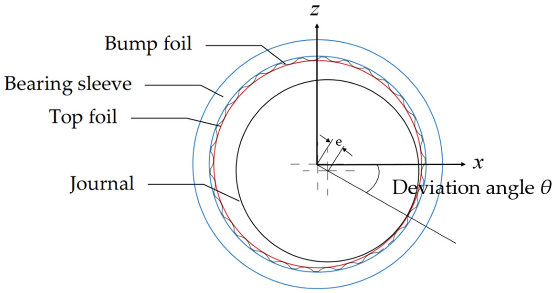
2.1. Elastohydrodynamic Theoretical Model of Bump Foil Air Bearing

The theoretical model of an air bearing needs to solve the compressible gas Reynolds equation and the gas film thickness equation.
Under stable conditions, that is, when temperature, viscosity, density, and other parameters do not change with time, the steady-state compressible gas Reynolds equation in the Cartesian coordinate system is expressed as [22]
x ρ h 3 μ p x + y ρ h 3 μ p y = 6 U d d x ρ h
In the field of science and engineering, it is important to use analytical methods to express equations in a dimensionless form. The core reason for this is to transform physical quantities into unitless quantities by introducing characteristic scales (such as characteristic length and velocity). After dimensionless, specific units no longer limit the equation and the form is more concise, which is convenient for solving differential equations and analysis, the dimensionless form (1) is reduced to
D L 2 λ p ¯ h 3 ¯ p ¯ λ + φ p ¯ h 3 ¯ p ¯ φ = Λ p ¯ h ¯ φ ,
The following dimensionless quantities are introduced:
λ = y L / 2 ; p ¯ = p p 0 ; h ¯ = h c ; x = R φ ; Λ = 6 μ w p 0 R c 2
where c represents bearing clearance, w represents rotor speed, μ represents gas dynamic viscosity, p0 represents ambient pressure, Λ represents bearing number, L represents bearing width, D represents journal diameter, R represents journal radius, x represents peripheral direction, y represents axial direction, p represents gas film pressure, φ represents circumferential angle, U represents circumferential velocity of journal, h represents air film thickness, and ρ represents lubrication gas density. The following is the coordinate diagram. The air bearing structure and the coordinate system are shown in Figure 1.
The structures of the bump foil and the flat foil are shown in Figure 2. The relationship between the thickness of the gas film and the structural deformation of the flat foil and the bump foil is [14]
h ¯ = 1 + ε cos φ + α ( p ¯ 1 ) ,
α = ( 2 p 0 s / C E ) ( t / t B ) 3 ( 1 v 2 ) .

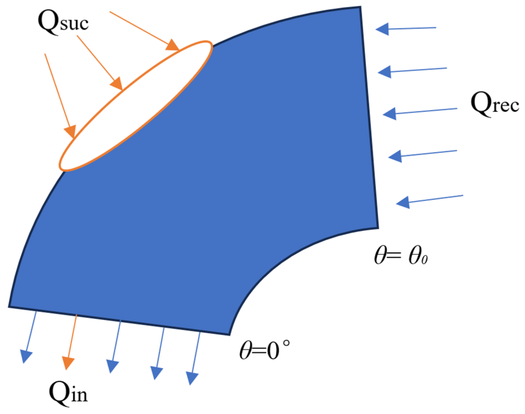
2.2. Theoretical Model of Temperature

Heat conduction occurs mainly through the collision between air molecules at high and low temperatures, transferring kinetic and heat energy. The heat conduction is proportional to the temperature gradient and inversely proportional to the thickness of the gas film. The thermal conductivity of gas is lower than that of solids and liquids.
Heat transfer through gas mainly occurs through fluid flow, which brings the heat from one place to another. There are many effects on the heat transfer of air, mainly including the viscosity, density, and flow rate of the fluid. The heat transfer in air bearings mainly includes convective heat transfer, which plays a leading role.
Due to the low thickness of the gas film, its radial velocity is slow. Compared with the heat conduction process in the circumferential direction and the axial direction, radial heat conduction dominates the whole heat transfer process, while radial heat convection has little effect on the overall heat transfer, which is basically negligible. The circumferential and axial velocity gradients are relatively larger than the radial velocity gradient, so the circumferential and axial thermal convection need to be considered. The steady-state gas film energy equation of an air bearing is [19]
ρ c p u T x + v T y + w T z = k 2 T z 2 + u p x + v p y + μ ( T ) u z 2 + v z 2 ,
where cp represents gas-specific heat capacity at constant pressure, k represents gas thermal conductivity, T represents the temperature of the gas film, u represents the velocity component in the circumferential direction, v represents the radial velocity component, and w represents the axial velocity component. Density is a function of temperature and pressure. Viscosity is a function of temperature. As the temperature increases, the molecular motion in the air becomes more intense, the molecular collision frequency increases, and the viscosity increases. The relationship between dynamic viscosity and temperature is [19]
μ ( T ) = λ ( T T r e f ) ,
where λ = 4 × 10⁻⁸ Pa·s/K and Tref = −185.59 K.
The dimensionless form (6) is reduced to
ρ ¯ ( u ¯ T ¯ φ + ν ¯ D L T ¯ y ¯ + w ¯ h ¯ T ¯ z ¯ ) = k 1 k 2 2 1 h ¯ 2 2 T ¯ z ¯ 2 + k 3 u ¯ p ¯ φ + k 3 ν ¯ D L p ¯ y ¯ + k 1 1 h ¯ 2 ( u ¯ z ¯ ) 2 + ( v ¯ z ¯ ) 2 + k 1 T ¯ h ¯ 2 ( u ¯ z ¯ ) 2 + ( v ¯ z ¯ ) 2 ,
k 1 = λ w ρ a c p R c 2 ,
k 2 = R w λ k ,
k 3 = p 0 ρ 0 c p ( T 0 T r e f ) ,
The following dimensionless quantities are introduced:
ρ ¯ = ρ ρ 0 ; u ¯ = u U ; v ¯ = v U ; ω ¯ = R C ω U ; T ¯ = T T 0 T 0 T r e f ; z ¯ = z h .
The velocity component is solved by the Navier–Stokes equation and continuity equation. After dimensionless transformation, they can be presented as follows:
u ¯ = 1 z ¯ + k 4 h ¯ 2 ( z ¯ 2 z ¯ ) p ¯ φ ,
ν ¯ = k 4 h ¯ 2 ( z ¯ 2 z ¯ ) ( D L ) ρ ¯ y ¯ ,
k 4 = p 0 2 μ w ( C R ) 2 ,
ω ¯ = k 4 h ¯ 3 ( D L ) 2 ( 1 ρ ¯ ρ ¯ y ¯ p ¯ y ¯ + 2 ρ ¯ y ¯ 2 ) ( z ¯ 3 3 z ¯ 2 2 ) k 4 h ¯ 2 ( 2 d h ¯ d φ p ¯ φ + h ¯ ρ ¯ ρ ¯ φ p ¯ φ + h ¯ 2 ρ ¯ φ 2 ) ( z ¯ 3 3 z ¯ 2 2 ) h ¯ ρ ¯ ρ ¯ φ ( z ¯ z ¯ 2 2 ) .
Through the central difference method, the difference discretization of the formula is as follows:
H 1 T ¯ i , j , k = A 1 T ¯ i + 1 , j , k + B 1 T ¯ i 1 , j , k + C 1 T ¯ i , j + 1 , k + D 1 T ¯ i , j 1 , k + E 1 T ¯ i , j , k + 1 + F 1 T ¯ i , j , k 1 + G 1 ,
A 1 = ρ ¯ u ¯ 2 Δ φ ,
B 1 = ρ ¯ u ¯ 2 Δ φ ,
C 1 = ρ ¯ ν ¯ 2 Δ λ D L ,
D 1 = ρ ¯ ν ¯ 2 Δ λ D L ,
E 1 = ρ ¯ ω ¯ 2 h ¯ Δ η k 1 k 2 2 h ¯ 2 ( Δ η ) 2 ,
F 1 = ρ ¯ ω ¯ 2 h ¯ Δ η k 1 k 2 2 h ¯ 2 ( Δ η ) 2 ,
G 1 = k 3 u ¯ p ¯ φ + k 3 ν ¯ D L p ¯ y ¯ + k 1 1 h ¯ 2 ( u ¯ z ¯ ) 2 + ( v ¯ z ¯ ) 2 ,
H 1 = k 1 1 h ¯ 2 ( u ¯ z ¯ ) 2 + ( v ¯ z ¯ ) 2 2 k 1 k 2 2 1 h ¯ 2 ( Δ η ) 2 .
Through Formula (17), it can be concluded that the temperature value of T1 (i, j, k) can be calculated as long as the six nodes around the node T1 (i, j, k) are calculated. Therefore, the boundary conditions of temperature are known. Through the continuous iterative calculation of Formula (17), the temperature distribution of the gas film can be calculated.
According to the theoretical working condition of bump foil air bearings, the boundary conditions of the temperature field are as follows:
When z = 0, the gas film temperature is the rotor temperature:
T | z = 0 = T r o t o r ,
When z = 1, the gas film temperature is the surface temperature of the flat foil:
T | z = 1 = T t o p ,
When θ = 0, the gas film temperature is the temperature of the ambient air:
T | θ = 0 = T i n .
The gas in an air bearing moves from the air inlet along the circumferential direction. The gas is subjected to the load, and the gas film pressure rises. When there is no load area, the pressure decreases, and a negative-pressure zone is formed in the falling area. Finally, it is connected to the environment, and the pressure rises to the ambient pressure. In the area of negative pressure, the bearing inhales gas from both ends. This process can supplement the gas leaked in the high-pressure region, and the specific process model is shown in Figure 3. When the ambient temperature is not equal to the temperature of the circulating gas film, it affects the temperature of the gas film at the next cycle inlet, which is no longer the ambient gas temperature.
The inlet film temperature update formula is as follows:
T ¯ in = T ¯ r e c Q ¯ r e c + T ¯ s u c Q ¯ s u c Q r e c + Q s u c ,
The suction volume formula is as follows:
Q s u c = x c r 2 π R 0 h v d z d x = 1 12 u c 3 p 0 D L θ 0 2 π h 3 p ¯ y ¯ d θ ,
The formula for air bearing flow after internal circulation is
Q r e c = 0 L / 2 0 h u d z d y = R ω C L 4 0 1 h ¯ c r d y ¯ 1 12 μ C 3 p 0 L D 0 1 h ¯ c r 3 p ¯ θ | θ = θ 0 d y ¯ ,
The dimensionless forms of Equations (30) and (31) are transformed into
Q ¯ s u c = Q s u c Q r = 1 12 0 σ 2 π h ¯ 3 P ¯ y ¯ | y = 1 d θ ,
Q ¯ r e c = Q r e c Q r = μ ω L 2 8 p 0 C 2 0 1 h ¯ r e c d y ¯ 1 12 ( L D ) 2 0 1 h ¯ σ r 3 P ¯ θ | θ = 0 d y ¯ ,
Q r = p 0 C 3 D μ L .
The ambient gas enters from the inlet, circulates in the circumferential direction for one cycle, mixes with the external ambient gas, and enters the cycle iteration again. The convergence criterion of gas film pressure and gas film temperature is
ε P = j = 2 n i = 2 m | P i , j k P i , j ( k 1 ) | j = 2 n i = 2 m | P i , j k | 10 5 ,
ε T = k = 2 q j = 2 n i = 2 m | T i , j , k ( r ) T i , j , k ( r 1 ) | k = 2 q j = 2 n i = 2 m | T i , j ( r ) | 10 5 .

3. Case Study

Taking the wave foil air bearing and gas parameters in Table 1 as an example [23], the software MATLAB 2020a was used to write a program. Firstly, the bearing structure parameters and gas parameters were assigned. Through the given gas film pressure, the gas film pressure distribution under the condition of constant temperature was calculated. Then, the initial temperature field boundary conditions were set and calculated, the gas film temperature distribution of the whole bearing was calculated, and the inlet temperature was updated. If the convergence condition was not reached, the boundary conditions were recalculated and iterated until convergence. The flow diagram of the numerical calculation is shown in Figure 4 below:

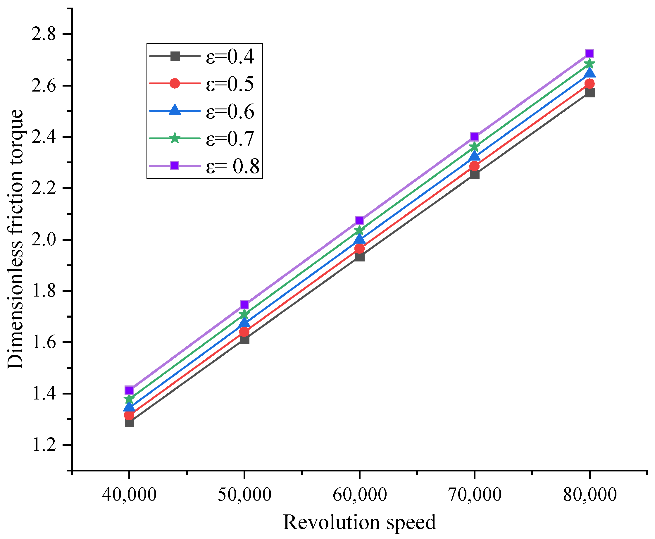
3.1. Static Characteristics Analysis

Figure 5 shows the comparison between the experimental data and the model calculation data at an air bearing speed of 30,000 r/min. The relationship between the load and the minimum gas film thickness data solved by the model in this paper was compared with the reference experimental data [24], as shown in Figure 5. It can be seen from Figure 5 that the model data are highly consistent with some of the experimental data, and the overall trend is the same, indicating the correctness of the model.
The steady-state characteristics analysis of the air bearing needed to combine the foil elastic mechanics model and the compressible gas equation, considering the comprehensive influence on its bearing capacity, stability, and stiffness exercised by eccentricity, rotational speed, and some structural size changes in the foil. By optimizing the geometric parameters of the air bearing (such as the thickness of the foil, the shape of the foil, etc.) and optimizing the operating parameters (speed, eccentricity, etc.), the performance of the air bearing can be improved. An in-depth study of the steady-state characteristics analysis can provide help in combination with the research of the physical field coupling model.
Figure 6 shows that when other parameters are constant, the numerical value of gas film bearing capacity changes under different eccentricities and different journal radius clearances. The bearing capacity of the gas film decreases with the increase in the journal radius gap and increases with the increase in eccentricity. When the eccentricity increases to a certain extent, the influence of changes in journal radius gap on the bearing capacity of the gas film becomes smaller.
Figure 7 shows the change in gas film bearing capacity under different foil thicknesses and different eccentricities. In a certain range, the gas film bearing capacity increases with the increase in foil thickness. The increase in thickness leads to an increase in foil stiffness and bearing capacity. Under the condition of high eccentricity, the influence of foil thickness on bearing capacity increases.
Figure 8 shows that, within a certain range, the length of the half-wave foil has an effect on the bearing capacity of the gas film. As the length of the half-wave foil increases, the bearing capacity of the gas film decreases. This is because, within a certain range, as the length of the half-wave foil increases, the stiffness of the wave foil decreases, the atmospheric film pressure cannot be supported, and the total gas film bearing capacity decreases.
The air itself is viscous, although its viscosity is not as high as the viscosity of the liquid; as long as there is shear relative motion, it produces viscous resistance, that is, friction resistance. The magnitude of the viscous force is related to the contact area and relative velocity. In the case of high-speed operation, the shear rate of the contact between the gas film and the shaft increases, and the friction torque generated by the viscous resistance may increase linearly. At the same time, in the case of high-speed operation, the thickness of the gas film changes so that the air bearing maintains a stable gas film. When the speed is low, although the take-off speed is reached, the thickness of the gas film becomes thinner, and local contact may occur. Especially in the take-off and stop state, the friction torque generated by the contact will increase significantly.
Figure 9 shows the change in dimensionless friction torque with increased rotational speed under different eccentricities after the air rotor reaches stable take-off speed. It can be seen intuitively that as the speed increases, the friction torque increases, showing an approximately linear relationship; moreover, at the same speed, with an increase in eccentricity, the friction torque also increases, and this also shows a close linear relationship.

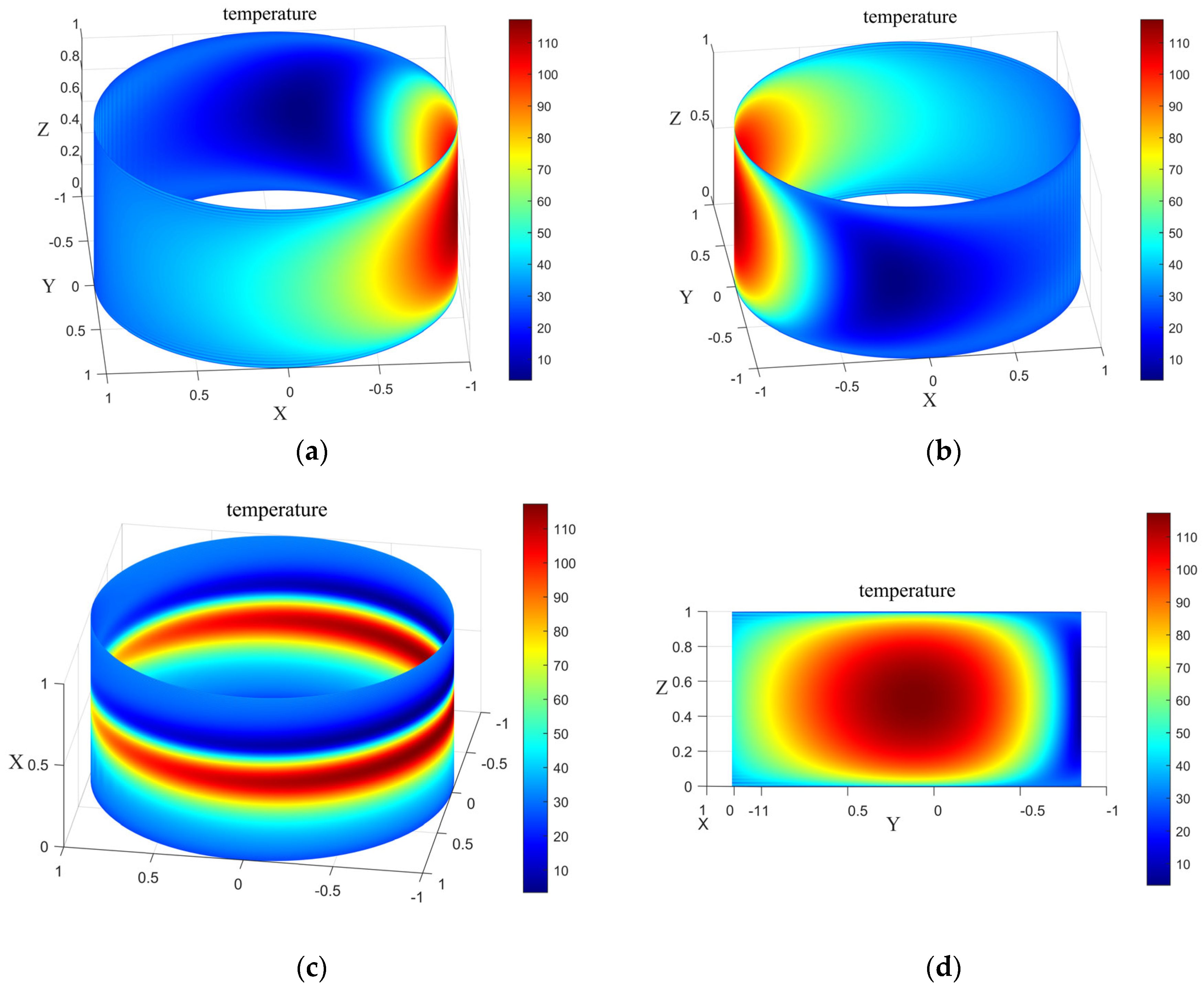
3.2. Thermal Characteristic Analysis

The fluid energy equation describes the energy conservation of fluid motion. Although in air bearings energy generation and dissipation are much smaller than with liquid lubrication, the influence of temperature cannot be ignored when running at high speed, and the distribution of temperature and the transfer of energy still need to be considered. In the process of gas lubrication, there are two main aspects of energy transfer: heat conduction and heat transfer.
Figure 10 shows the temperature distribution of the middle section with a rotation speed of 40,000 rpm and an eccentricity of 0.84. From the diagram, it can be seen that the temperature change law in the thickness direction of the gas film is as follows: the gas enters the inlet, is heated by viscous shear along the circumference, and the temperature rises rapidly. After reaching the vicinity of the maximum load of the gas film, the temperature decreases to a certain extent and then rises with air pressure. The temperature rises again, and then mixes with the inlet temperature again to re-enter the bearing. Because the rotor rotates continuously, the shaft surface continuously passes through the high-temperature and low-temperature regions—and most of the shaft is a hollow shaft with cooling air flowing through—so the temperature of the shaft surface remains constant.
Figure 11 shows the temperature of the middle surface. It can be seen from Figure 11a,b that the coordinate line (1, 0, z) is the air inlet, the air inlet is clockwise, and the initial temperature is the ambient temperature. After the initial gas enters the bearing, the temperature rises rapidly. When the gas film pressure reaches the maximum near the load, it can be seen that this is a high-temperature gathering area. Then, due to the decrease in air pressure, the gas film temperature decreases, because at this time, considering the existence of negative pressure, the temperature decreases rapidly (when there is negative pressure, there is no contact between the flat foil and the wave foil, the conditions change, negative pressure occurs, and external environment gas enters quickly), and the temperature of the two free-end faces of the bearing is the ambient temperature. It can be seen from Figure 11c that the temperature of the gas film on the middle surface is distributed in the circumferential direction: after the gas enters, the temperature gradually rises to the maximum temperature of the circumference of this layer and then drops to the ambient temperature. When the pressure returns to positive pressure, the gas film temperature rises again until it returns to the air inlet. It can be seen from Figure 11d that the temperature of the gas film in the middle section is distributed in the axial direction: the temperature on both sides of the bearing presents an axisymmetric law. First, the ambient temperature increases to reach this layer’s maximum axial temperature, and then it decreases to the ambient temperature.
As can be seen from Figure 12, when the speed increases from 30,000 rpm to 55,000 rpm, the maximum gas film pressure increases continuously and the maximum gas film temperature in the bearing also increases continuously. When the rotational speed increases, the gas flow velocity inside the bearing increases, and the gas is subjected to centrifugal force in the bearing gap, causing the gas to collide with the bearing surface, thereby increasing the pressure of the gas near the bearing surface. Although the air bearing is in normal operation, there is no direct contact between the shaft and the flat foil. Although this ‘non-contact’ condition is achieved by the gas film pressure, the collision between the air molecules is more intense and the temperature increases due to the increase in rotational speed. The influence of the maximum pressure and the maximum temperature on the relative speed change is close.
Figure 13 shows the gas film temperature distribution under different eccentricities. It can be clearly seen that the high-temperature concentration area changes with the change in eccentricity, and with an increase in eccentricity, the gas film temperature also increases. At the same time, it can be seen that with an increase in eccentricity, the high-temperature area is more concentrated.
Although air bearings have the characteristics of low friction and low loss, the influence of temperature on the performance of an air bearing cannot be ignored in actual operating situations. Due to the high speed of operation, the heat generated causes the temperature in the bearing to rise, and its performance is affected. Figure 14 below shows the influence of eccentricity on the maximum dimensionless gas film pressure and load under the condition of 40,000 r/min, both considering temperature and not considering temperature. Figure 14a shows that, considering the influence of temperature, the maximum gas film pressure becomes larger under different eccentricity working conditions; Figure 14b also shows that, considering the influence of temperature, the load becomes larger.
By calculating the maximum film pressure difference between the values obtained when considering temperature and not considering temperature, it is found from Figure 15 that with a change in eccentricity, the influence intensity also changes. The larger the eccentricity is, the larger the calculated pressure difference is, and the greater the temperature influence is. Similarly, the impact on the load is the same as the pressure, and with an increase in eccentricity, the impact is greater.
There are various scenarios for the application of air bearings, such as in-air circulation machines, hydrogen fuel cell compressors, fuel-free turbine blowers, etc. The working environments of these machines are different, and the ambient temperatures are also very different. Therefore, it is necessary to consider the influence of ambient temperature on the performance of air bearings, especially their bearing capacity and stability.
Figure 16 shows, within a certain range, the influence of ambient temperature on the maximum temperature and load of the gas film. It can be seen that as the ambient temperature increases, the maximum temperature of the gas film continues to rise, and the increase rate gradually decreases and tends to a stable value. Because of the greater temperature difference between the ambient gas and the gas running in the bearing, the gas temperature in the bearing decreases after mixing. When the temperature difference is small, the temperature of the gas film increases. Because the rotor surface is affected by the cooling air flow, the rotor surface temperature is basically determined, which leads to an increase in the ambient temperature which has little effect on the film temperature.
When the ambient temperature changes, the stability of the foil air bearing is affected. It can be seen from Figure 17 that as the ambient temperature increases, the deviation angle decreases, the vertical component of the gas film decreases, and the stability increases. When the difference between the ambient temperature and the gas temperature in the bearing is gradually reduced, the energy exchange between the inside and outside of the bearing is reduced. The heat generated by the viscous shear temperature is transmitted through the cooling air flow inside the rotor, and the stability is enhanced.

4. Conclusions

This paper studies the characteristics of wave-foil-type air bearings. Through theoretical modeling, equation derivation, and numerical calculation, a theoretical model of a bearing and a theoretical model of its temperature field are established, the boundary conditions are set, and the finite difference method is used to solve the distribution of the air film temperature. The influence of parameters such as the rotational speed of the rotor shaft, the thickness of the wave foil, and eccentricity on friction torque and load are analyzed; the influence of the main parameters on air film temperature and the influence of ambient temperature on air film temperature are analyzed. The following conclusions were drawn:
(1)
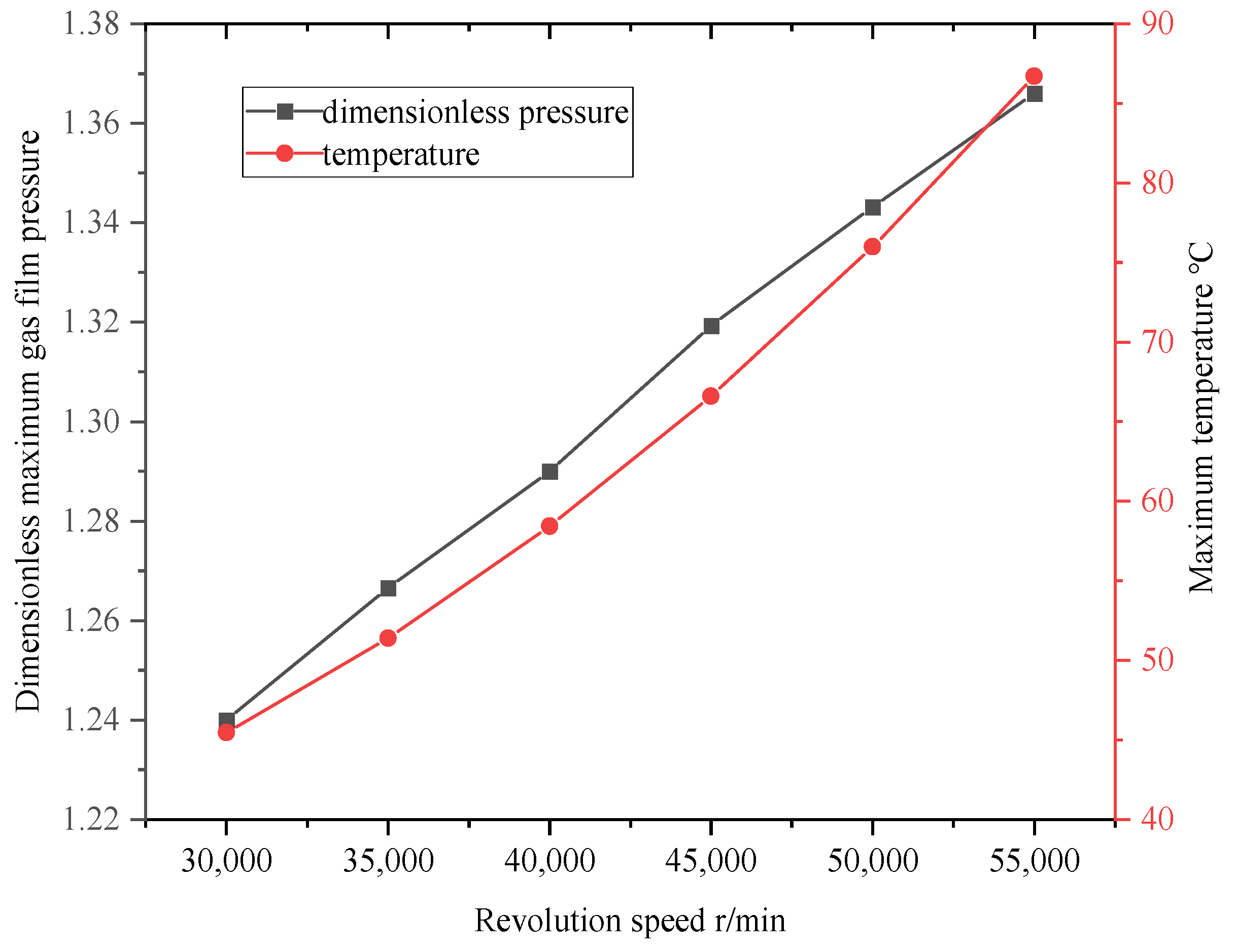
The friction torque of the air bearing increases linearly with its rotational speed, and changes in eccentricity do not affect the increasing speed; within a certain range, the bearing load increases with the increase in wave foil thickness or the decrease in half-wave foil length. In a certain range, with the increase in journal radius clearance, the bearing load decreases. When under high-eccentricity conditions, the effect of journal radius clearance can be ignored; with increasing speed, the maximum temperature of the air film and the maximum pressure of the air film increase, considering the thermal deformation of the rotor, wave foil, flat foil, and other components caused by the increasing temperature, which restricts the speed of the rotor.
(2)
The temperature distribution in the gas film changes significantly along the circumference. In the section from the inlet to the maximum load of the gas film, the temperature of the gas film rises rapidly, after which the temperature decreases due to the decrease in air pressure, and finally, in the negative pressure region, the gas is absorbed, the pressure increases, and the gas reaches the inlet, where it mixes again with the ambient gas and re-enters the bearing. The high-temperature region is concentrated in the load region. Therefore, a cooling gas flow can be passed through the wave foil near the eccentricity angle to achieve a localized cooling effect. Changes in eccentricity lead to changes in the temperature concentration region, and the localized cooling region needs to be changed when the bearing is subjected to different load conditions.
(3)
The influence of whether or not the thermal field is considered on the bearing characteristics was investigated. Under the condition of considering the temperature field, the pressure of the air film and the load of the bearing will be somewhat higher than their values under the condition of not considering the temperature field, and the degree of this influence increases with the increase in eccentricity. When the bearing is at a low speed, the maximum temperature of the air film does not change much. Therefore, in the process of practical application, when the bearing is in a low-speed state, one should not consider the temperature conditions for the preliminary assessment of some bearing performance parameters.
(4)
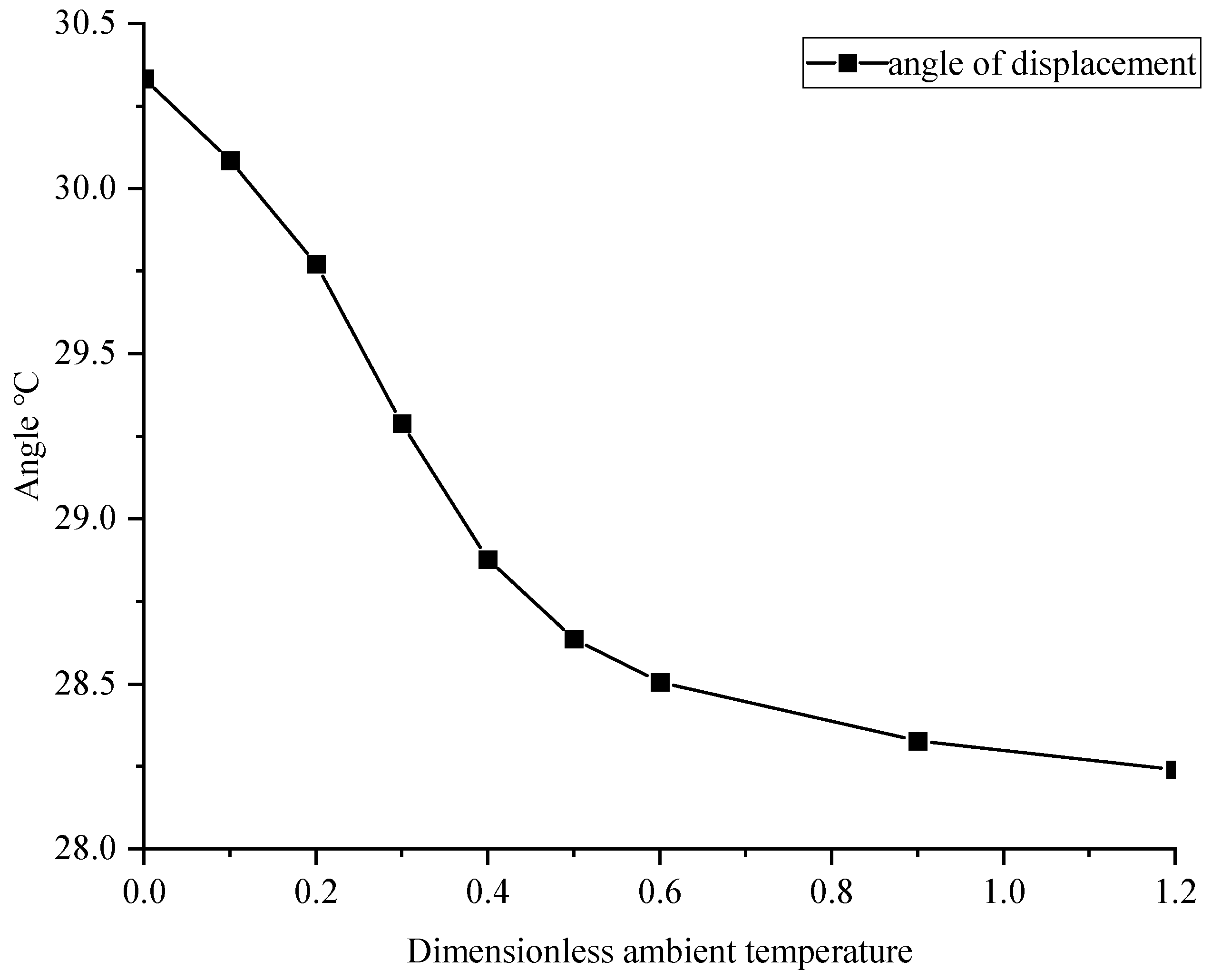
Bearing load characteristics are affected by different ambient gas temperatures. Within a certain range, as the ambient temperature increases, the maximum gas temperature inside the bearing increases, but the degree of increase gradually decreases, and the degree of increase in load capacity also decreases. With an increase in ambient temperature, the stability of the bearing is improved to a certain extent. Therefore, the temperature difference between the inside and outside of the bearing working area should not be too large, which affects bearing capacity and stability.
Bump foil gas bearings are operated under the coupling of multiple physical fields, including the force field, flow field, and temperature field. When rotating at high speed, the gas film pressure formed between the journal and the bearing surface constitutes the flow field. It not only provides the bearing with the support force of the bearing rotor and forms the dynamic mechanical balance in the force field, but it is also closely related to the speed and eccentricity of the rotor, which directly affect the stability and bearing capacity of the bearing. In the process of operation, the viscous friction, compression, and expansion of gas produce heat, which causes changes in the temperature field. High temperatures lead to a decrease in bearing material performance and a change in gas film viscosity, which affect the flow field and gas film stiffness. The uneven distribution of the temperature field also causes the thermal deformation of the bearing structure and changes the distribution of the force field. In addition, the impact force and vibration in the force field react with the flow field and the shape of the gas film, destroying the uniformity of the gas film, aggravating friction heat generation, and further changing the temperature field distribution. Therefore, an in-depth study of the coupling relationships between these intertwined and interacting physical fields is a key technical path to break through the performance bottleneck of bump foil gas bearings and promote their engineering applications.

Author Contributions

Conceptualization, D.L. and Z.Z.; methodology, D.L. and Z.Z.; software, J.L. and Z.Z.; validation, Z.Z.; formal analysis, Z.Z.; investigation, J.L. and Z.Z.; resources, D.L.; data curation, J.L. and Z.Z.; writing—original draft preparation, Z.Z.; writing—review and editing, D.L. and Z.Z.; visualization, J.L. and Z.Z.; supervision, J.L.; project administration, D.L.; funding acquisition, D.L. All authors have read and agreed to the published version of the manuscript.

Funding

This work was supported by funding of Shanghai Committee of Science and Technology (21010504000).

Institutional Review Board Statement

Not applicable.

Informed Consent Statement

Not applicable.

Data Availability Statement

The original contributions presented in this study are included in the article. Further inquiries can be directed to the corresponding author.

Acknowledgments

The authors would like to express their sincere gratitude to Shanghai Institute of Technology.

Conflicts of Interest

The authors declare no conflicts of interest.

References

  1. Lee, W.; Kim, D. Rotordynamics of a rotor supported by foil bearings under various housing excitation. Tribol. Int. 2024, 199, 109956. [Google Scholar] [CrossRef]
  2. Shi, T.; Wang, H.; Yang, W.; Peng, X. Mathematical modeling and optimization of gas foil bearings-rotor system in hydrogen fuel cell vehicles. Energy 2024, 290, 130129. [Google Scholar] [CrossRef]
  3. Chakraborty, B.; Biswas, N.; Chakraborti, P. An Investigation to Find the Effects on Air Foil Bearing by the Variation of Foil’s Structural Parameters. J. Sci. Ind. Res. 2023, 82, 603–608. [Google Scholar] [CrossRef]
  4. Carpino, M.; Peng, J.P. Theoretical performance of a hydrostatic foil bearing. J. Tribol. 1994, 116, 83–89. [Google Scholar] [CrossRef]
  5. Peng, Z.C.; Khonsari, M.M. On the limiting load-carrying capacity of foil bearings. ASME J. Tribol. 2004, 126, 817–818. [Google Scholar] [CrossRef]
  6. San Andrés, L.; Kim, T.H. Analysis of gas foil bearings integrating FE top foil models. Tribol. Int. 2009, 42, 111–120. [Google Scholar] [CrossRef]
  7. Shi, T.; Huang, H.; Peng, X.; Feng, J.; Guo, Y. Experimental study on the static and dynamic performances of gas foil bearings for the centrifugal air compressor used in fuel cell vehicles. Int. J. Energy Res. 2022, 46, 4417–4433. [Google Scholar] [CrossRef]
  8. Li, W.; Wang, G.; Feng, K.; Zhang, Y.; Wang, P. CFD-based investigation and experimental study on the performances of novel back-flow channel aerostatic bearings. Tribol. Int. 2022, 165, 107319. [Google Scholar] [CrossRef]
  9. Shahdhaar, M.A.; Yadawad, S.S.; Khamari, D.S.; Behera, S.K. Numerical investigation of slip flow phenomenon on performance characteristics of gas foil journal bearing. SN Appl. Sci. 2020, 2, 1–18. [Google Scholar] [CrossRef]
  10. Samanta, P.; Murmu, N.C.; Khonsari, M.M. The evolution of foil bearing technology. Tribol. Int. 2019, 135, 305–323. [Google Scholar] [CrossRef]
  11. Salehi, M.; Swanson, E.; Heshmat, H. Thermal features of compliant foil bearings—Theory and experiments. J. Tribol. 2001, 123, 566–571. [Google Scholar] [CrossRef]
  12. Lee, D.; Kim, D. Thermohydrodynamic analyses of bump air foil bearings with detailed thermal model of foil structures and rotor. J. Tribol. 2010, 132, 021704. [Google Scholar] [CrossRef]
  13. Talmage, G.; Carpino, M. Thermal structural effects in a gas-lubricated foil journal bearing. Tribol. Trans. 2011, 5, 701–713. [Google Scholar] [CrossRef]
  14. Peng, Z.C.; Khonsari, M.M. A thermohydrodynamic analysis of foil journal bearings. J. Tribol. 2006, 128, 534–541. [Google Scholar] [CrossRef]
  15. San Andrés, L.; Kim, T.H. Thermohydrodynamic analysis of bump type gas foil bearings: A model anchored to test data. J. Eng. Gas Turbines Power 2010, 132, 042504. [Google Scholar] [CrossRef]
  16. Sim, K.; Kim, T.H. Thermohydrodynamic analysis of bump-type gas foil bearings using bump thermal contact and inlet flow mixing models. Tribol. Int. 2012, 48, 137–148. [Google Scholar] [CrossRef]
  17. Aksoy, S.; Aksit, M.F. A fully coupled 3D thermo-elastohydrodynamics model for a bump-type compliant foil journal bearing. Tribol. Int. 2015, 82, 110–122. [Google Scholar] [CrossRef]
  18. Gao, Q.H.; Sun, W.J.; Zhang, J.Z.; Li, J.Z.; Zhang, J.Y. Thermo-Elasto-Hydrodynamic Analysis of Gas Foil Bearing Considering Thermal Effects. Int. J. Mech. Sci. 2025, 288, 110008. [Google Scholar] [CrossRef]
  19. Jia, H.; Hu, N.; Yin, B.; Zhou, Z.; Xu, B. Research on foil thermal features of hydrodynamic air foil bearing with the Three-dimensional heat transfer model. Therm. Sci. Eng. Prog. 2023, 40, 101737. [Google Scholar] [CrossRef]
  20. Mahner, M.; Bauer, M.; Schweizer, B. Numerical analyzes and experimental investigations on the fully-coupled thermo-elasto-gasdynamic behavior of air foil journal bearings. Mech. Syst. Signal Process. 2021, 149, 107221. [Google Scholar] [CrossRef]
  21. Kim, D.; Ki, J.; Kim, Y.; Ahn, K. Extended three-dimensional thermo-hydrodynamic model of radial foil bearing: Case studies on thermal behaviors and dynamic characteristics in gas turbine simulator. Therm. Sci. Eng. Prog. 2012, 134, 052501. [Google Scholar] [CrossRef]
  22. Li, C.; Du, J.; Yao, Y. Study of load carrying mechanism of a novel three-pad gas foil bearing with multiple sliding beams. Mech. Syst. Signal Process. 2020, 135, 106372. [Google Scholar] [CrossRef]
  23. Gu, Y.; Lan, X.; Ren, G.; Zhou, M. An efficient three-dimensional foil structure model for bump-type gas foil bearings considering friction. Friction 2021, 9, 1450–1463. [Google Scholar] [CrossRef]
  24. Xu, Z.; Li, C.; Du, J. Modeling and static characteristics study of the double-layer bump gas foil bearing. Tribol. Int. 2021, 164, 107202. [Google Scholar] [CrossRef]
Figure 1. Air bearing structure diagram and coordinate system diagram.
Applsci 15 07584 g001
Figure 2. Structure diagram of wave foil and flat foil.
Applsci 15 07584 g002
Figure 3. Calculation model of inlet mixed gas.
Applsci 15 07584 g003
Figure 4. Flow chart of calculation procedure.
Applsci 15 07584 g004
Figure 5. Comparison diagram of model data and experimental data.
Applsci 15 07584 g005
Figure 6. Influence of journal radius clearance on gas film bearing capacity under different eccentricities.
Applsci 15 07584 g006
Figure 7. The influence of the thickness of the wave foil on the gas film load-carrying capacity under different eccentricities.
Applsci 15 07584 g007
Figure 8. The influence of half-wave foil length on gas film load-carrying capacity under different eccentricities.
Applsci 15 07584 g008
Figure 9. The curve of the friction torque of the air bearing varies with the rotational speed and eccentricity rate.
Applsci 15 07584 g009
Figure 10. The temperature distribution of a gas film cross-section.
Applsci 15 07584 g010
Figure 11. (a) A positive plane diagram of the temperature distribution of the split gas film in the middle plane. (b) A reverse diagram of the temperature distribution of the gas film on the middle surface. (c) A circumferential gas film temperature law diagram of the middle plane. (d) The gas film temperature distribution in the middle plane bearing area.
Applsci 15 07584 g011
Figure 12. Variation in maximum pressure and maximum temperature of gas film with rotating speed.
Applsci 15 07584 g012
Figure 13. (a) The temperature distribution of the middle surface gas film with an eccentricity of 0.44. (b) The temperature distribution of the middle surface gas film with an eccentricity of 0.64. (c) The temperature distribution of the middle surface gas film with an eccentricity of 0.84.
Applsci 15 07584 g013
Figure 14. (a) Considering the influence of temperature on the maximum pressure of the gas film under different eccentricities. (b) Considering the influence of temperature on the bearing load under different eccentricities.
Applsci 15 07584 g014
Figure 15. Effect of temperature on gas film pressure and load intensity under different eccentricities.
Applsci 15 07584 g015
Figure 16. Effect of ambient temperature on maximum temperature and load of gas film.
Applsci 15 07584 g016
Figure 17. The influence of ambient temperature change on the deflection angle.
Applsci 15 07584 g017
Table 1. Foil-type air bearing parameters and gas parameters.
ParameterValue
R (m)5 × 10⁻²
L (m)7.5 × 10⁻²
C (m)1 × 10⁻⁴
p0 (Pa)1.01325 × 10⁵
Eb (N/m2)2.14 × 1011
ν0.3
P (Pa)1.01325 × 10⁵
s (m)4.064 × 10⁻³
l (m)1.717 × 10⁻³
R0 (m)2.655 × 10⁻³
tb (m)7.62 × 10⁻⁵
Disclaimer/Publisher’s Note: The statements, opinions and data contained in all publications are solely those of the individual author(s) and contributor(s) and not of MDPI and/or the editor(s). MDPI and/or the editor(s) disclaim responsibility for any injury to people or property resulting from any ideas, methods, instructions or products referred to in the content.

