Article

Multi-Parameter Structural Optimization of Shale-Hydrocarbon-Dissolvable Ball Seat Slips Based on Safety and Performance Assessment Methods

1
School of Mechanical and Precision Instrument Engineering, Xi’an University of Technology, Xi’an 710048, China
2
School of Mechanical and Electrical Engineering, Southwest Petroleum University, Chengdu 610500, China
3
MOE Key Lab of Oil and Natural Gas Equipment, Southwest Petroleum University, Chengdu 610500, China
*
Author to whom correspondence should be addressed.
Appl. Sci. 2025, 15(13), 7554; https://doi.org/10.3390/app15137554
Submission received: 27 April 2025 / Revised: 22 June 2025 / Accepted: 25 June 2025 / Published: 5 July 2025

Abstract

As the core component for fracturing plug anchoring, dissolvable ball seat (DBS) slip performance directly determines the success of fracturing operations. However, frequent failures, such as tooth structural fractures, casing damage, and the slip breaking off entirely, compromise DBS reliability during high-pressure fracturing. This study investigates DBS slip anchoring performance through finite element analysis (FEA), anchoring performance tests, and structural optimization. We established a comprehensive safety and performance assessment framework incorporating strength criteria, peak contact pressure, and anchoring uniformity. Comparative stress analysis of nail-type versus block-type slip systems revealed superior performance in block-type configurations, demonstrating more uniform slip–casing interfacial stress distribution. To further enhance the anchoring performance of the block-type slip, a structural parameter analysis was conducted to identify critical factors influencing anchoring capability, with tooth apex angle and inclination angle determined as key parameters. The influence laws of these parameters on anchoring performance were systematically investigated. Subsequently, a multi-parameter optimization methodology was employed to optimize the structural configuration of the block-type slip. The optimization results revealed that an optimal slip tooth apex angle of 80° or 85° and an inclination angle of 70° enhance the safety and anchoring reliability of the dissolvable ball seat slip while providing a theoretical framework for future slip structure design improvements. At present, the new structure of the soluble ball seat structure proposed in this paper has been successfully applied in some oil fields. Field tests show that the anchoring efficiency has been significantly improved. This research not only provides a theoretical framework for the design of sliding structures, but also offers reliable technical support for the efficient development of deep oil and gas resources.

1. Introduction

With rapid economic growth, China’s energy demand continues to rise, posing significant challenges to achieving carbon neutrality due to the nation’s heavy reliance on coal-based electricity generation [1,2]. To address this issue, accelerating the exploration and development of oil and gas resources while enhancing production efficiency has become imperative [3,4,5,6]. However, conventional hydrocarbon reserves are insufficient to meet escalating demand, necessitating a strategic shift toward unconventional resources. Notably, shale gas, tight oil, and tight gas—along with other emerging alternatives such as coalbed methane (CBM) [7,8] and gas hydrates [9,10]—are increasingly critical in sustaining domestic energy supply [11,12,13,14,15,16]. The exploitation of unconventional reservoirs is hindered by their inherently poor rock properties [17,18,19] and pronounced formation heterogeneity [20,21,22], rendering conventional hydraulic fracturing methods ineffective for optimal resource recovery [23,24,25,26]. To address these challenges, staged volume fracturing technology has emerged as a critical solution for the efficient development of tight oil and gas reservoirs, demonstrating substantial improvements in hydrocarbon production rates [27,28]. Among recent innovations, dissolvable ball seat (DBS) systems have gained rapid adoption in volume fracturing operations due to their rapid dissolution kinetics, full-bore production capability, and streamlined operational process. This technology has driven transformative advancements in horizontal well segmentation and multi-cluster fracturing techniques, significantly enhancing reservoir stimulation efficiency [29,30]. However, during volumetric fracturing operations, the DBS system is subjected to significant shock loads and vibrational stresses, which can compromise the anchoring integrity between the DBS and casing. These dynamic conditions may lead to the axial displacement of the DBS, seal slippage, or even leakage failures. Furthermore, under extreme loading conditions, the casing teeth may shear, resulting in complete anchoring failure [31]. Figure 1 illustrates typical failure modes, including slip tooth fracture, casing damage, and the slip breaking off entirely. To address these critical issues, this study conducts a comprehensive anchoring performance analysis of the DBS slip structure. Through advanced simulation techniques, we systematically evaluate the mechanical behavior and reliability of the DBS anchoring system under operational conditions.
Current investigations into the seating performance of downhole seal tool slips primarily employ three methodological approaches: experimental laboratory testing, finite element analysis (FEA), and theoretical modeling. Within the theoretical domain, Liang et al. [32] conducted seminal work addressing suspension failure mechanisms in completion packers for offshore thermal recovery wells. Their study introduced innovative structural optimization through the development of non-concentric full-contact molded slips. The research team systematically validated the enhanced suspension capacity of this redesigned slip configuration through comprehensive theoretical calculations coupled with finite element simulations, demonstrating significant improvements in operational reliability. Tang et al. [33] conducted a comprehensive investigation into the pressure-bearing capacity and pipe wall interaction characteristics of robotic sealing slips. Through this rigorous methodology, the researchers successfully optimized the slip configuration, achieving significant enhancements in both sealing efficiency and operational durability. Tan et al. [34] optimized toothed dissolvable bridge plug parameters through finite element analysis and orthogonal experiments, significantly enhancing anchoring performance. Wang et al. [35] optimized the segmented slip structure of small-diameter dissolvable bridge plugs by adjusting the slip cone angle and hoop dimensions to accommodate shale gas horizontal well casing deformations. Through mechanical analysis and experimental validation, the modified design demonstrated enhanced anchoring and load-bearing capacity, meeting segmented fracturing operational requirements. Han et al. [36] investigated slip anchoring mechanics through slip-line theory, finite element analysis, and experimental validation, quantifying casing penetration depth and evaluating parameter and load effects on anchoring performance. Mykola Karpenko [37] evaluated the connection efficiency of pipe fittings in the hydraulic system of transportation machinery based on the finite element analysis method and obtained the influence laws of two 45° and 90° angle fitting connection types on pressure drop, turbulence model, energy loss, and flow coefficient. In terms of experimental research, Liu [38] experimentally determined the anchoring load range for a specific packer shackle configuration through controlled laboratory testing. Zheng et al. [39] further advanced this understanding by investigating slip formation mechanics, with particular emphasis on how critical geometric parameters—including top angle, inclination angle, and wedge angle—influence slip–casing contact characteristics. In finite element research, recent computational studies have significantly advanced the understanding of slip–casing interaction dynamics. Chen et al. [40] employed finite element analysis (FEA) to characterize stress distribution patterns in slip structures, identifying the central region as the primary casing penetration zone. Building on this foundation, Tang [41] developed a sophisticated FEA model to investigate casing-pressure-induced slip damage mechanisms, subsequently optimizing critical shackle parameters. For specific field applications, Li et al. [42] designed Y422 retrievable bridge plugs tailored for marginal reservoir development in Daqing oilfield, conducting comprehensive FEA to elucidate structural stress distribution characteristics in slip components. Zhang et al. [43] developed a hydraulic pump degradable bridge plug design, employing computational fluid dynamics to systematically evaluate its sealing capacity, anchorage behavior, and erosion resistance under flow conditions. Complementing this work, Wang [44] conducted a finite element analysis of slip–casing interactions, deriving critical stress–displacement relationships that informed subsequent shackle design optimizations. Hao et al. [45,46] investigated fracture mechanisms in integral slips during bridge plug sealing operations. Through integrated fracture testing and computational modeling, the researchers optimized the stress slot design of dissolvable bridge plug integral slips. This systematic approach resulted in significantly enhanced anchoring performance and pressure-bearing capacity.
Existing studies have extensively investigated slip anchorage performance in conventional packer tools, but research gaps remain regarding novel dissolvable ball seat (DBS) systems. The current literature predominantly focuses on traditional metal slips, which serve as critical components for ensuring reliable casing–wall anchorage. However, the tight sticking performance of DBS systems presents unique challenges that directly determine the success of horizontal well fracturing operations. This study addresses these knowledge gaps through three key contributions: (1) the establishment of a mechanical model for DBS cavity structure, (2) the comprehensive finite element analysis of anchorage performance, and (3) the systematic optimization of tooth geometry (top angle and inclination angle). The resulting structural improvements enhance the metal anchorage capability of DBS systems, ultimately meeting the stringent requirements of horizontal well fracturing applications.

2. Materials and Methods

2.1. Setting Process and Mechanical Analysis of DBS Slip

2.1.1. Analysis of the Fracturing Setting Process of DBS Slip

As depicted in Figure 2, the DBS slip features a multi-flap tile configuration uniformly distributed along its circumference. The slip base integrates a hardened slip block, comprising an external hoop ring for enhanced stability during operation and an internal tapered surface that engages with the sliding body. Furthermore, the tailstock incorporates precision guide slots to constrain the radial displacement of the shackle. During DBS seating, the seating tool’s axial force induces relative motion between the sliding body and tailstock. The sliding body radially displaces the cavity’s inner surface, forcing it into contact with the casing wall. The hardened cavity block subsequently embeds into the casing, effecting DBS anchoring. Upon reaching a predetermined displacement, the interlocking horse-tooth profiles between the sliding body and tailstock disengage, allowing for DBS release and completing the seat seal process.

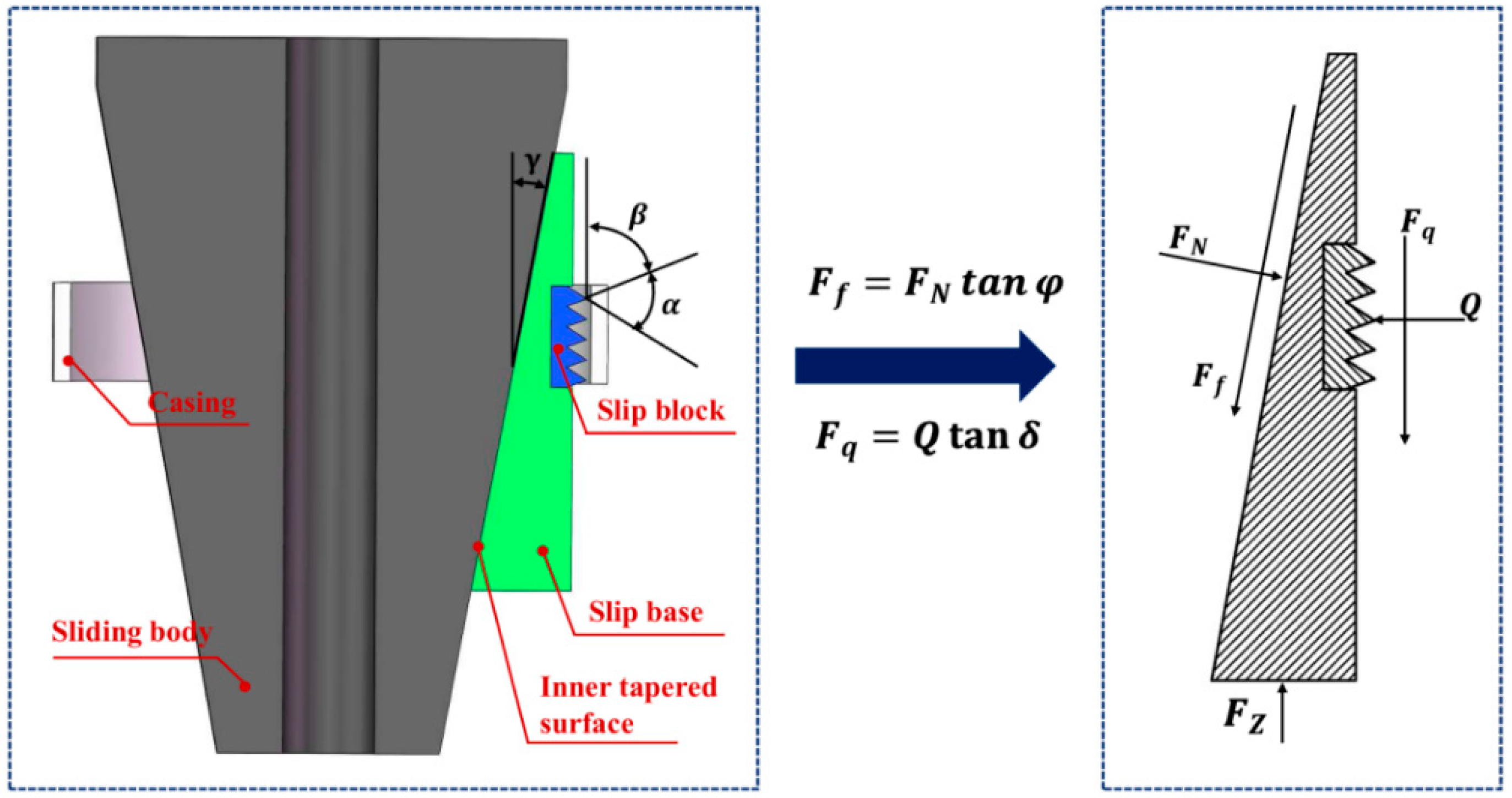
2.1.2. Mechanical Analysis of the Slip During Setting Process

The slip assembly serves as the primary anchoring mechanism during DBS setting and fracturing operations, securely locking the tool to the casing wall. This critical function prevents the axial displacement of the DBS while maintaining effective pressure-sealing integrity. However, during service, potential slip failure or excessive casing wall damage may occur, which could compromise well integrity and lead to serious safety incidents, ultimately threatening the safety of hydrocarbon production operations. Consequently, the mechanical analysis of the DBS mounting slips is essential. The DBS slip incorporates a multi-flap design. For analytical purposes, we isolate a single flap segment and conduct a stress distribution analysis. Figure 3 illustrates both the structural configuration and force distribution of this slip segment.
During DBS setting operations, the slip assembly experiences multiple loading conditions including radial casing wall reaction forces, compressive loading from the sliding body, frictional forces at the sliding body/tailstock interface, and setting forces transmitted through individual cavity elements from the tailstock. Based on static equilibrium principles, the force balance on the slip must satisfy the following equations [47]:
Q = F N cos γ F f sin γ
F z F q = F N sin γ + F f cos γ
F f = F N tan φ
F Z = W Z / n
F q = Q tan δ
where Q is the radial load at the interface between the single-flap slip segment and casing inner wall, N; F N is the normal contact forces transmitted from the sliding body to single-flap slip, N; F f is the friction between the sliding body and the single-flap slip, N; F Z is the sealing force acting on single-valve slip, N; F q is the friction between single-flap slip and casing, N; W Z is the DBS seating load, N; γ is the tilt angle of contact surface between the slip and sliding body, °; φ is the friction angle between slip and sliding body, °; n is the number of slip pieces.
Combining Equations (1) through (5), we derive the following:
Q = W Z / n Q tan δ tan ( γ + φ )
where δ is the friction angle between the cavity and the casing wall, °.
Equation (6) can be transformed to yield the following:
Q = W Z n tan ( γ + φ ) + tan δ
with the contact pressure distribution at the slip tooth–casing interface during occlusion as follows:
σ = Q A
where: Q is the contact pressure between the slip teeth and the inner wall of the casing, N/mm2; A is the contact area between the slip teeth and the inner wall of the casing, mm2.
The structural geometry demonstrates that the slip–casing contact surface area is characterized by Equation (9):
A = m a θ π D t 360 1 tan β + tan α + β π 2
where m is the number of single-flap slip teeth; a is the slip teeth bite into the casing; θ is the single-flap slip with rounded angle; Dt is the diameter of casing inner wall; α is the slip tooth apex angle; β is the slip tooth inclination angle.
Combining Equations (8) and (9), we obtain the following.
σ = 360 W Z n tan γ + φ · m a θ π D t 1 tan β + tan α + β π 2
The preceding mechanical analysis establishes the computational model for determining interfacial contact pressure between the casing and slip assembly during setting and sealing operations. As demonstrated by Equation (10), both the slip tooth apex angle and inclination angle significantly influence the slip–casing contact pressure distribution. This pressure relationship directly governs the slip’s anchoring performance, thereby providing critical theoretical guidance for optimizing structural design parameters.

2.2. The Index Establishment of DBS Slip Anchoring Performance Assessment Method

The slip anchoring mechanism, as a critical component of the downhole DBS, plays a pivotal role in determining overall system performance. The failure of the slip anchoring function can directly compromise hydrocarbon production efficiency and jeopardize downhole operational safety. Through the comprehensive analysis of primary failure modes in DBS slips, this study establishes three key evaluation criteria, strength criteria, peak contact pressure, and anchoring uniformity, to systematically assess the anchoring performance of DBS slips.

2.2.1. Structural Safety Evaluation Index: Strength Criteria

During horizontal-well-staged fracturing operations, the casing experiences significant indentation due to the seating force, subjecting both the slip teeth and casing to substantial stress concentrations. Furthermore, when a flanged shackle is employed, the tooth grooves on the slip base may also endure high stress levels, necessitating the rigorous strength verification of the slip base structure.
To prevent damage to both the DBS slip and casing, the maximum equivalent stress is adopted as a critical safety evaluation metric for the DBS anchoring system. The assessment criteria stipulate that (1) the maximum equivalent stress on the slip teeth, slip base, and casing must remain below the yield strength of their respective materials, and (2) the maximum equivalent stress should be minimized to ensure reliable DBS anchoring performance under downhole conditions.

2.2.2. First Index of Slip Anchoring Performance Evaluation: Peak Contact Pressure Criteria

During horizontal well fracturing operations, maintaining substantial interfacial contact pressure between slip teeth and casing wall is critical for ensuring reliable DBS anchoring integrity. This study employs the peak contact pressure at the slip–casing interface as a key performance indicator for DBS anchoring capability, establishing a corresponding evaluation criterion. The proposed criterion states that anchoring robustness increases proportionally with the maximum attainable contact pressure under applied setting loads.

2.2.3. Second Index of Slip Anchoring Performance Evaluation: Contact Uniformity Criteria

The operational environment during horizontal well fracturing exhibits significant complexity, where dynamic shock loads and vibration phenomena may compromise DBS integrity, potentially inducing downward migration or even resulting in seal failure due to slippage. A critical determinant of anchoring reliability lies in the interfacial pressure distribution characteristics between slip elements and casing. Non-uniform contact pressure distribution adversely affects anchoring stability, whereas improved uniformity directly enhances anchoring performance.
This study establishes a quantitative evaluation framework for slip anchoring performance based on contact uniformity criteria utilizing two key parameters: (1) mean interfacial contact pressure and (2) contact pressure standard deviation.
The proposed evaluation criteria specify that optimal anchoring requires the maximization of mean contact pressure and the minimization of pressure deviation. Only under the above conditions can spatially uniform contact distribution be achieved.

3. Analysis and Results

3.1. Numerical Analysis of the Anchoring Performance of DBS Slips

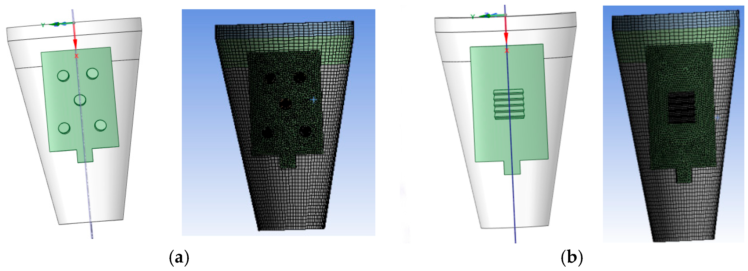
3.1.1. Finite Element Model of DBS Slips

Two predominant slip configurations employed in fracturing operations are the slip nail and slip block designs. This study conducts a numerical analysis of their respective anchoring performance characteristics. The DBS assembly was computationally simplified based on its fundamental seating and anchoring mechanics, with particular focus on structural influences on anchoring efficacy. Consequently, non-essential components such as sealing elements were omitted while the core structural assemblies were retained: the sliding body, slip units, and casing interface.
Given the axi-symmetric nature of the dissolvable ball seat slip arrangement, a single-slip unit was modeled to optimize computational efficiency. Mesh generation employed an intelligent structured grid algorithm. The resulting mesh configuration is presented in Figure 4.
The material of the DBS sliding body and slip base is dissolvable aluminum alloy, and the material of the slip block is cemented carbide. The mechanical and chemical properties of these materials, including dissolution rates under downhole conditions, are systematically presented in Table 1.
According to the working principle of DBS slip, the side of the casing and the outer surface were set as a fixed constraint, and the axial displacement of the lower surface of the slip base is 0 mm. The downward displacement is applied to the upper end surface of the sliding body, and the normal displacement of the contact surface between the slip base and the base is 0 mm.
After the boundary conditions are imposed, the support reaction force at the upper surface of the sliding body is obtained for different displacements of the sliding body. The stress, strain, and contact pressure between the block/nail and the casing wall are obtained when the seating force is not greater than 9t, i.e., the seating force on a slip block is not greater than 1.6 tons.

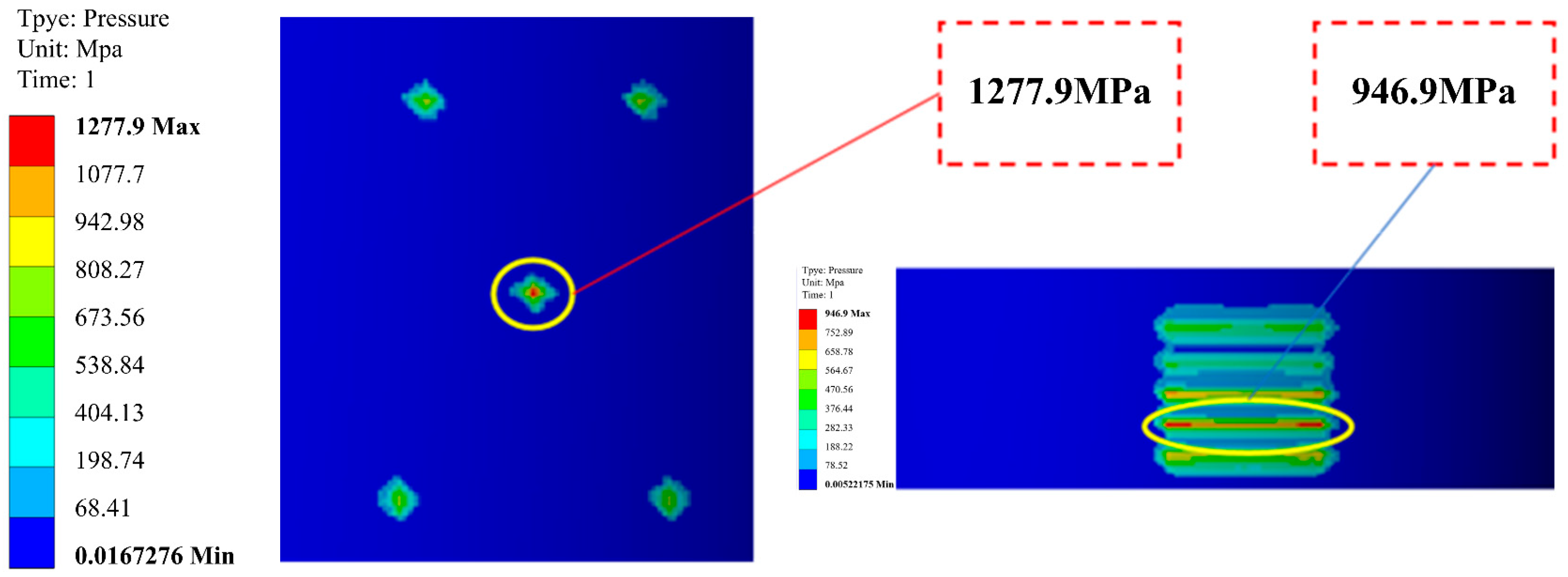
3.1.2. Analysis of Calculation Results Between the Slip Snail and Slip Block

Utilizing the established computational model, a finite element analysis of the DBS slip setting mechanism was conducted. This study comparatively evaluates the mechanical performance between nail-type and block-type slip configurations through the quantitative analysis of von Mises stress distribution in slip and casing and interfacial contact pressure evolution during plug setting.
Contact pressure distributions between the two slip types (nail type and block type) and casings were calculated and illustrated separately in Figure 5 under seating forces. The peak contact pressure at the slip insert/casing wall interface attained 2338.5 MPa when employing the nail-type slip. In comparison, the contact pressure distribution exhibited greater uniformity along the upper slip segment, where the peak interfacial pressure reached 1161.3 MPa at the block-type slip tooth/casing contact zone.
The contact pressure distribution analysis reveals that the nail-type slip exhibited concentrated stress near the interfacial contact zone, with peak pressures reaching 1879 MPa. In contrast, the block-type slip demonstrate significantly improved pressure distribution uniformity, maintaining a peak interfacial pressure of 776 MPa. Both slip components utilized identical material with a yield strength of 981 MPa. Notably, the peak stress on the nail-type slip exceeds the material yield strength by 93.4%, indicating a high likelihood of pronounced plastic deformation in the slip nail. Such deformation could potentially culminate in slip anchoring failure during downhole operations.
The stress distribution along the casing wall for the two structural slip configurations is depicted in Figure 6. For the casing integrated with embedded slip nails, the peak contact pressure reaches 1277.9 MPa (73.2% above yield strength), whereas the casing with embedded slip blocks exhibits a peak pressure of 946.9 MPa (28.3% above yield). The yield strength of the casing material is specified as 738 MPa. The simulation results indicate that the block-type slip configuration demonstrates superior anchoring performance compared to the block-type slip design.
Finite element analysis (FEA) was conducted on two existing slip configurations to characterize the equivalent stress states of the slip–casing systems. Simulation results indicate that the nail-type slip configuration induces significantly higher stresses in both the slip elements and the casing wall, leading to insufficient anchoring stability. In contrast, the block-type slip configuration demonstrates uniform stress distribution across the slip–casing interface, enabling superior anchoring performance. However, the influence of the critical structural parameters (e.g., tooth profile angle, contact surface roughness) of the slip block on anchoring efficiency remains undefined, necessitating further exploration to optimize parameter combinations for enhanced reliability.

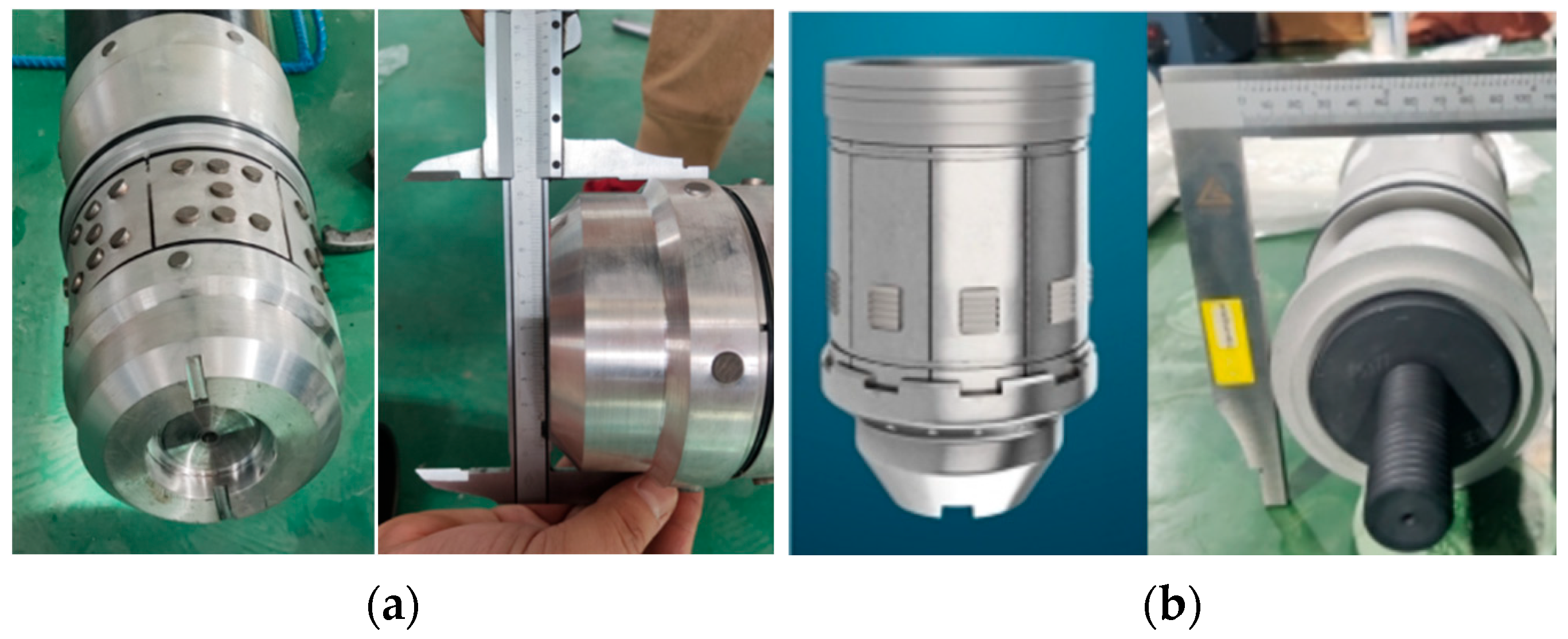
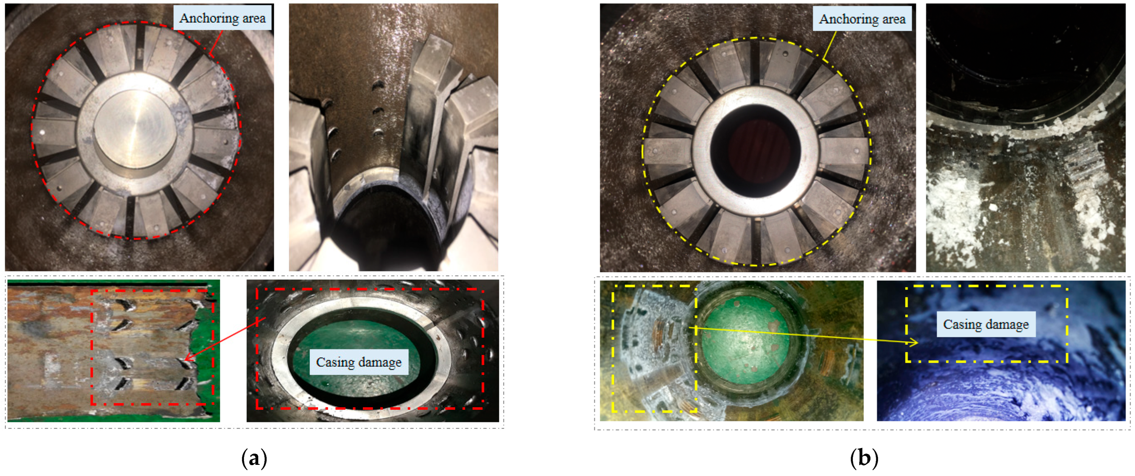
3.1.3. Anchoring Performance Tests of Dissolvable Ball Seat Slips

To further investigate the anchoring performance discrepancies between nail-type and block-type slips (Figure 7), a servo-hydraulic universal testing machine was employed to conduct comparative tests on dissolvable ball seat slips under simulated downhole pressure conditions. The experiments aimed to quantify anchoring efficiency by evaluating the wear mechanisms of slip elements and casing wall integrity under equivalent setting loads, as defined by API RP 11D1. Test results were then cross-validated against finite element analysis (FEA) simulations to calibrate numerical models.
The experimental investigation was conducted according to the following methodology:
(1) Experimental Design
Comparative Analysis of Anchoring Damage: Under identical anchoring setting loads, a comparative evaluation was performed to assess the anchoring damage characteristics between slip nail and slip block configurations.
Casing Wall Damage Assessment: Under the same anchoring load conditions, the casing wall damage induced by slip nail and slip block mechanisms was experimentally examined and analyzed.
(2) Test Apparatus and Materials
The experimental setup included the following key components:
A universal testing machine (Model: HDT106A, Serial No.: 1908112) was sourced from Hanzheng Testing Technology Co., Ltd., Guanghan, China;
Slip blocks and slip nails (see Figure 7 for illustrations);
Data acquisition and processing equipment.
The WYC Microcomputer-controlled high-pressure testing and monitoring system is presented in Figure 8. This automated pressure detection apparatus was designed for precision control across both high-pressure (100 MPa) and ultra-high-pressure (600 MPa) regimes. Experimental results demonstrated that the successful setting of the nail-type slip was achieved at 22 MPa, whereas a minimum setting load of 24 MPa was required for effective deployment of the block-type configuration. To ensure reliable setting performance across both designs, a standardized setting pressure of 24 MPa was selected for comparative evaluation in this study.
(3) Experimental Testing Procedure
1) Commissioning of equipment and tooling fixtures: We ensured that all equipment and fixtures were in optimal operational condition and properly calibrated for testing.
2) Preparation of equipment data acquisition system: We configured mechanical test parameters (e.g., loading rate, pressure thresholds) in the data acquisition system according to predefined protocols.
3) Loading process: We applied the specified setting force incrementally via the testing machine, with the load range strictly controlled between 0 and 40 MPa. We continuously recorded the stroke displacement of the sliding body within the range of 0 to 90 mm, ensuring the real-time monitoring of mechanical responses.
4) Collection and documentation of test results: We documented damage observations on slips and casing walls. We recorded the final anchoring status of the ball seat, referencing the anchoring mechanism schematic for comparative analysis.
(4) Analysis of the Experimental Results
The results of the comparative analysis via the slip anchoring test are as follows.
As illustrated in Figure 9, the degree of damage to the casing inner wall was qualitatively analyzed through the application of the nail-type structure during the anchoring process. Stress concentration was observed in the casing wall at the locations where the slip nails were engaged with the casing. Consequently, severe damage was induced in the casing wall. Under the same loading conditions, less damage was inflicted on the casing wall by the block-type structure, which was demonstrated to be beneficial for maintaining the structural integrity of the casing. Additionally, the damage morphology of the block-type structure appeared more uniformly distributed compared to that of the nail-type structure. Better mechanical performance was exhibited by the block-type structure in terms of stress distribution. Therefore, the comparative test results confirmed that the block-type structure was proven to be superior to the nail-type structure in anchoring applications.

3.2. Effects of Structural Parameters on Slip Anchoring Performance

Following the finite element simulation results described above, the block-type slip exhibited superior performance. Under this configuration, the stress distributions across the slip block, casing, and slip base were relatively uniform, and the primary factor influencing the anchoring capacity of the slip was determined to be the structural parameters of the slip block. To further investigate the effects of these parameters on slip anchoring performance, the tooth apex angle and tooth inclination angle of the slip block were selected as variables for finite element simulations. The optimal combination of these angles was sought through systematic parameter variations.
Finite element software Ansys Workbench 2022 R1 was employed to simulate the slip behavior after individually modifying each parameter. The structural parameters are shown in Figure 10. By comparing the experimental results, the influence of each structural parameter on the anchoring performance was quantified.

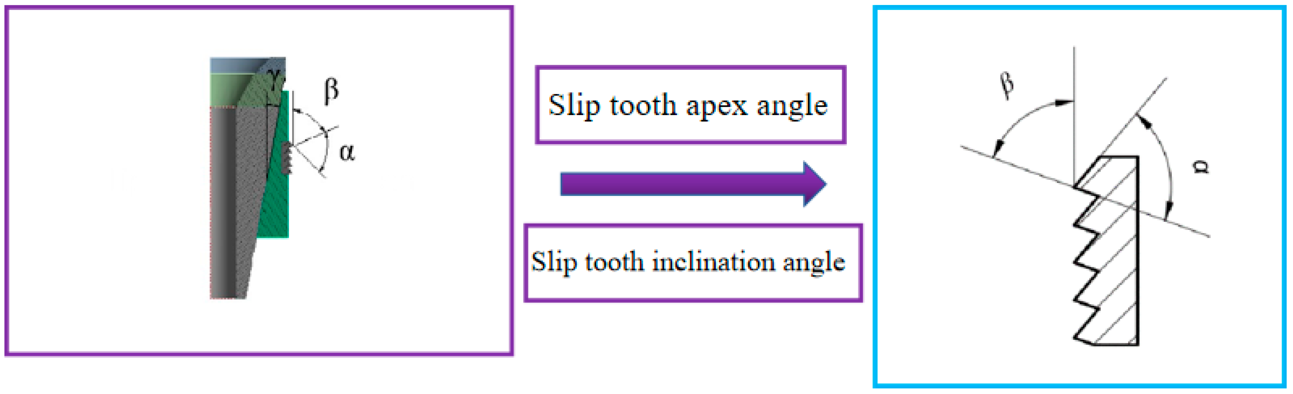
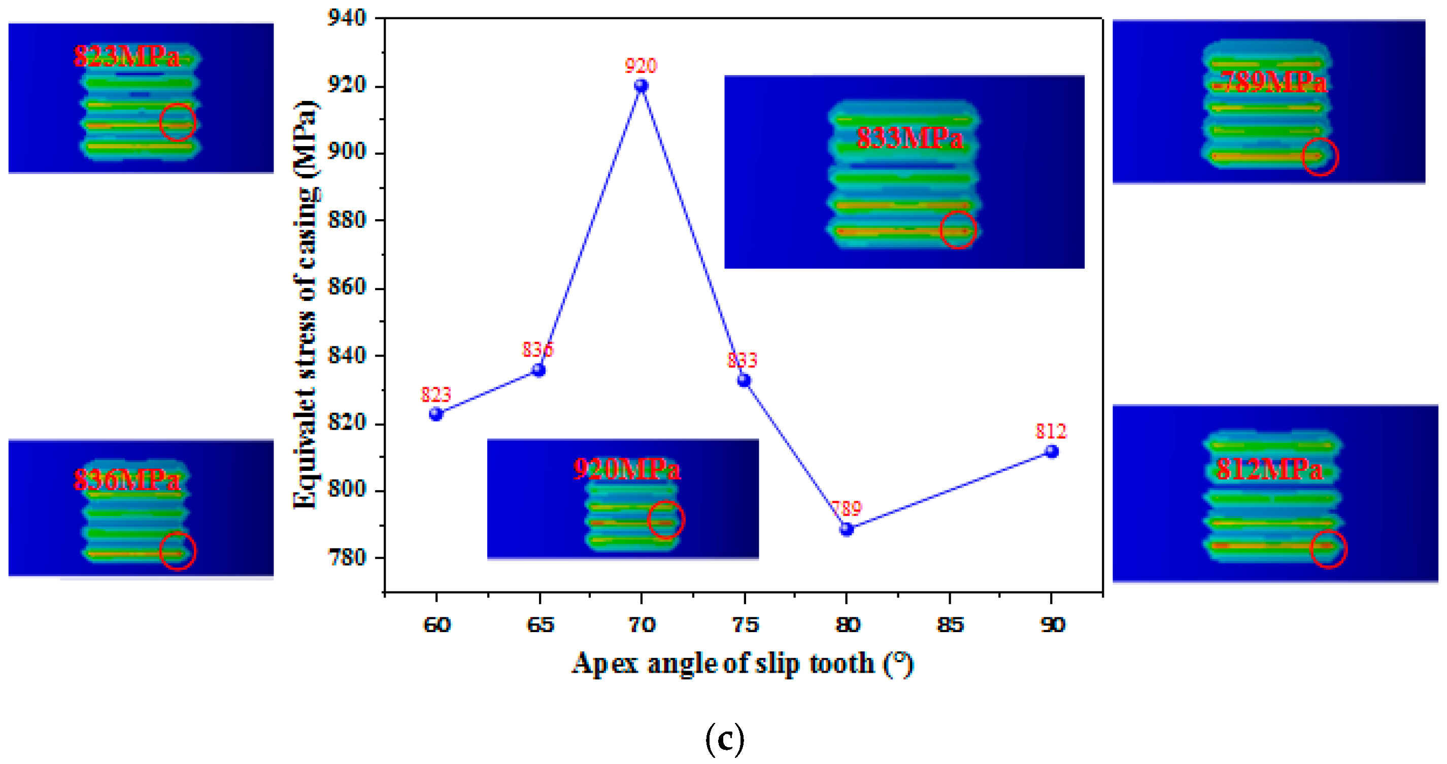
3.2.1. The Effect Law Analysis of Slip Tooth Apex Angle on Anchoring Performance

Finite element models were developed for slip tooth apex angles of 60°, 65°, 70°, 75°, 80°, and 90°. Numerical simulations were conducted to investigate the influence of varying slip tooth apex angles on the contact pressure distribution between the slip and casing wall. The resulting contact pressure cloud diagrams for each apex angle configuration are presented in Figure 11a, while the corresponding contact pressure indicators are summarized in Table 2.
As the apex angle of the slip tooth was increased, the contact pressure between the slip and the casing wall rose. However, when the apex angle reached 90°, the peak contact pressure between the slip and the casing was found to decrease.
The standard deviation of the contact pressure between the casing and the slip was determined to be the smallest at slip tooth apex angles of 60° and 65°, while the largest deviation was recorded at 70°. Nevertheless, the deviation remained at a relatively low level, and the contact pressure distribution between the slip and the casing was noted to be fairly uniform, with no significant stress concentration observed.
When the slip tooth apex angle fell within the range of 70° to 80°, the contact pressure between the slip and the casing was measured to be higher, which was considered beneficial for achieving a secure anchoring effect.
The stress distribution of the slip block at different slip tooth apex angles was analyzed and presented in Figure 11b. As the slip tooth apex angle was increased, a decreasing trend in slip block stress was observed. At an apex angle of α = 80°, the slip block stress was found to increase slightly compared to α = 75°, though it remained at a relatively low level.
With lower stress exerted on the slip block, the slip was deemed safer during seating and fracturing operations. Within the slip tooth apex angle range of 75° to 90°, the slip block was subjected to minimal stress, enhancing structural safety.
The casing stress distribution, illustrated in Figure 11c, exhibited minimal variation across different slip tooth apex angles. During slip anchoring, the casing was found to experience only minor damage, with no significant casing failure observed. Based on the comprehensive stress analysis of the casing, the optimal slip tooth apex angle α was preliminarily determined to range between 75° and 90°.

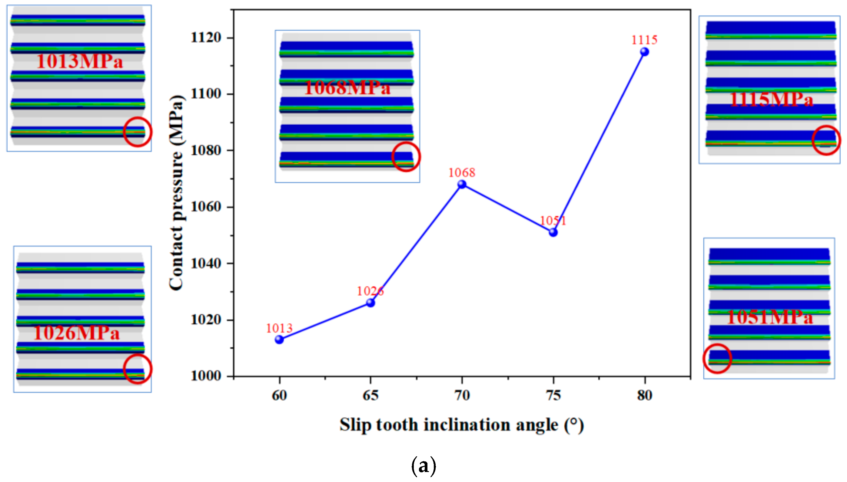
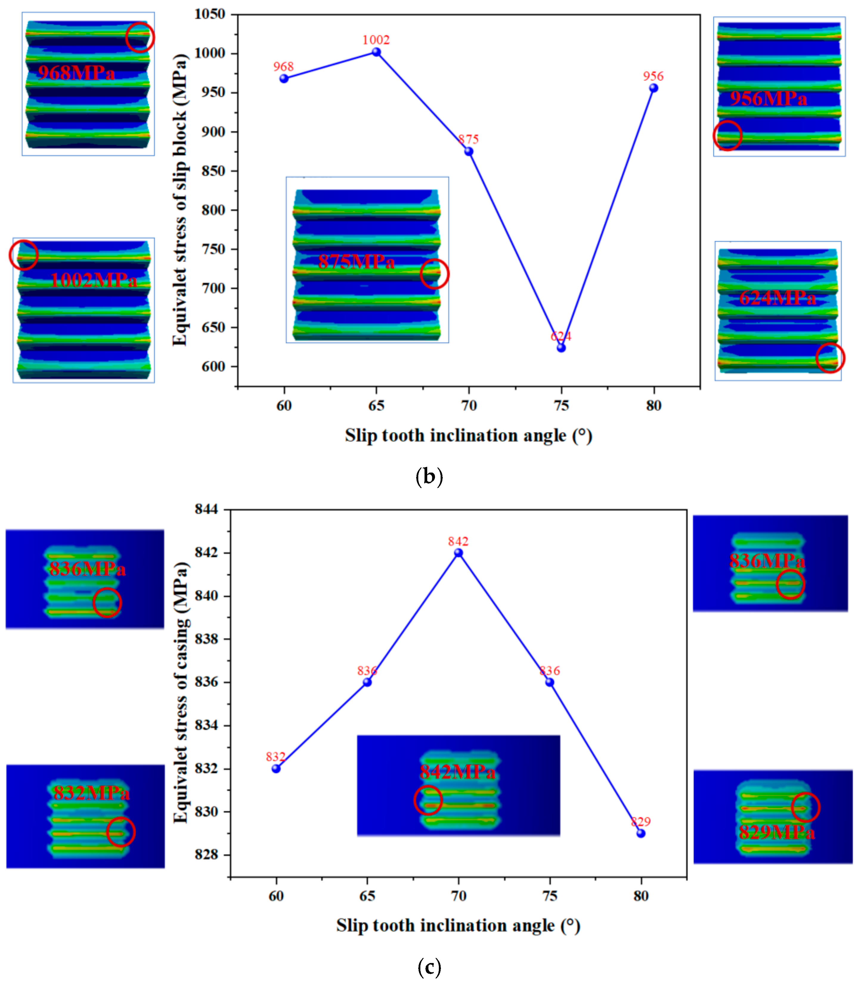
3.2.2. The Effect Law Analysis of Slip Tooth Inclination Angle on Anchoring Performance

The inclination angle of slip teeth was found to exert significant influence on the contact pressure distribution between slips and casing wall. It was observed that, when the inclination angle of slip teeth was excessively large, the slips demonstrated reduced capability to effectively penetrate the casing wall. Conversely, an insufficient inclination angle was shown to compromise the slip teeth’s unidirectional load-bearing capacity.
A finite element model of the slip was constructed for slip tooth inclination angles of 60°, 65°, 70°, 75°, and 80°. Numerical simulations were performed to systematically investigate the effect of slip tooth inclination angle on cavity seating contact characteristics. The analysis was conducted to establish the correlation between different slip tooth inclination angles and the corresponding contact pressure distribution patterns at the slip–casing interface.
The contact pressure between the casing and the slip at varying slip tooth inclination angles is presented in Figure 12a, while the corresponding contact pressure indicators are tabulated in Table 3. As the inclination angle of the slip teeth was increased, a slight upward trend in the contact pressure between the slip and the casing was observed; however, this change was minimal. The standard deviation of the contact pressure reached its peak when the inclination angle was 70°, which depicts the stress distribution across different inclination angles.
The equivalent stress of the slip first decreased and then increased with increasing inclination angle, reaching a minimum value at 75°. This indicated that the slip structure exhibited optimal stability at inclination angles of 70° and 75°; Figure 12b,c. show the equivalent stress distribution in the casing under different slip tooth inclination angles. Negligible variation was detected across all tested angles, ensuring that the casing remained structurally intact during the setting and sealing processes.
Based on the analysis of stress distribution across varying inclination angles, 70° and 75° were identified as the preferred slip tooth inclination angles for reliable anchoring performance. Additionally, it was observed that the fifth slip tooth exhibited higher contact pressure with the casing compared to other teeth, indicating uneven stress distribution. Further investigation is required to explore the multi-factor influences on the mechanical behavior of slip structures.

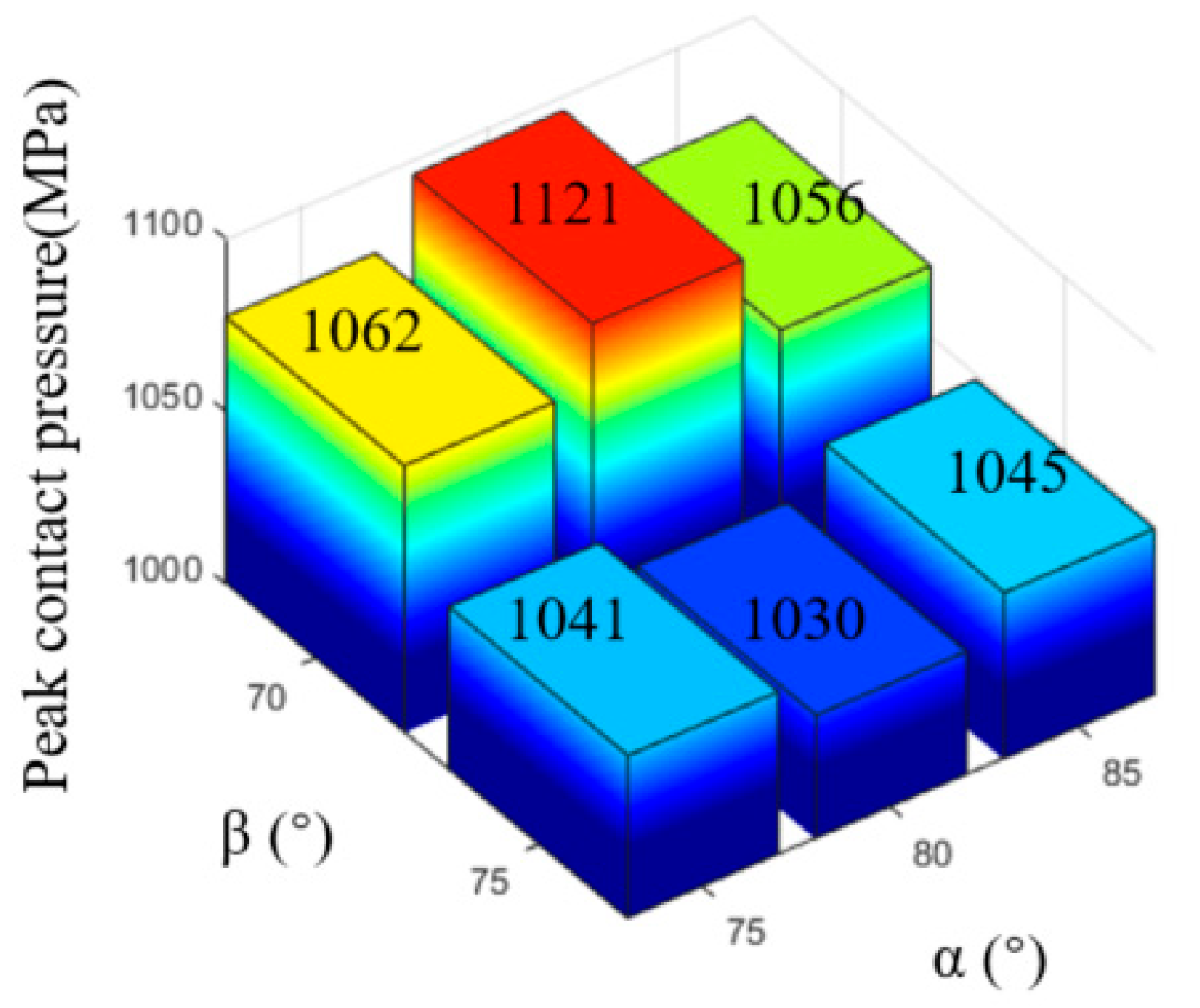
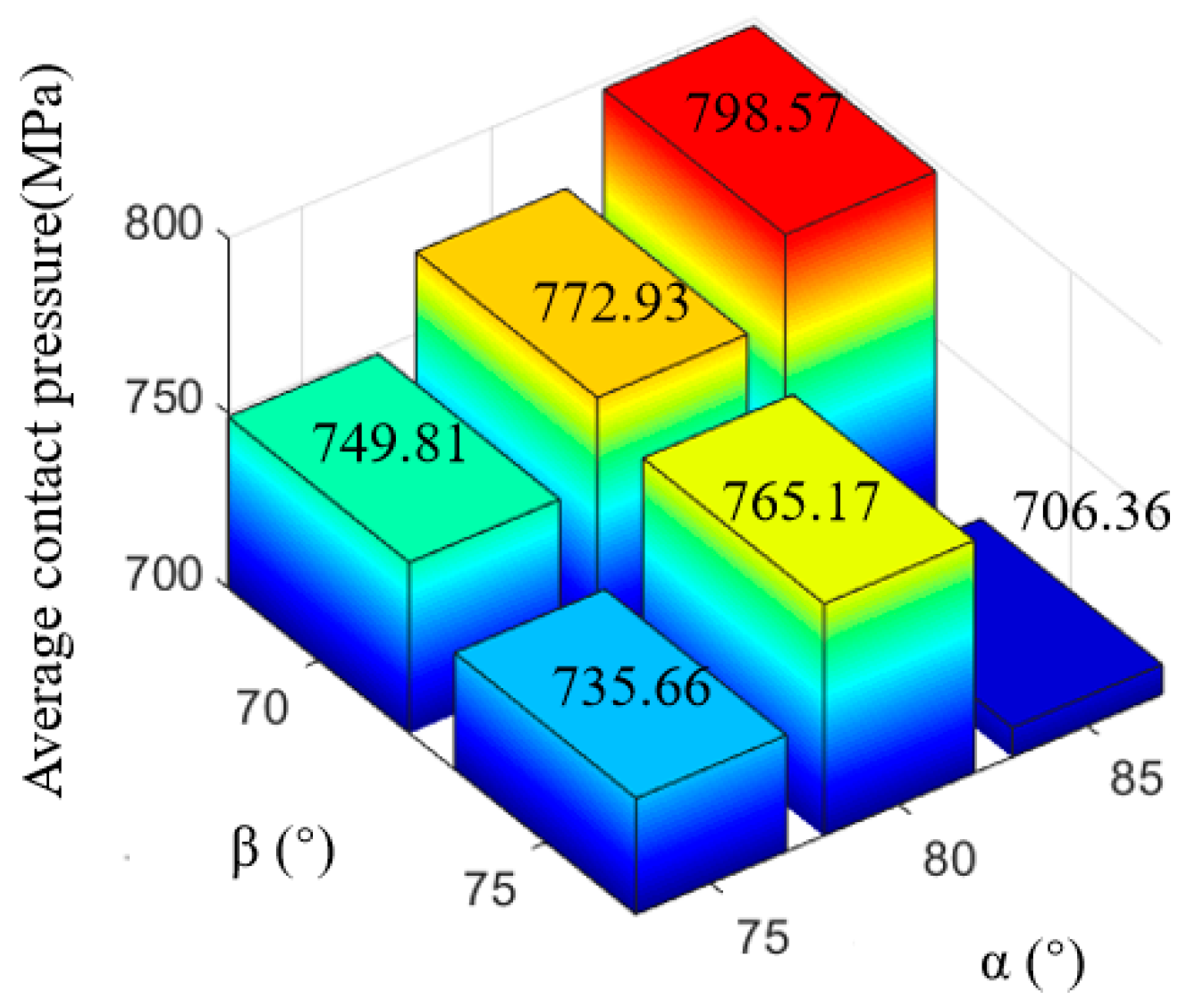
3.3. Structural Parameter Optimization Analysis of the Dissolvable Ball Seat

As previously mentioned, to ensure the safety of the slip structure, the apex angle of the slip teeth was recommended to range between 75° and 90°, while the slip teeth inclination angle could be set at either 70° or 75°. When the apex angle of the slip teeth was designed at 75° or 80°, a higher contact pressure between the slip and the casing was observed, which was found to enhance the solid anchoring of the slip.
To further study the influence of the structural parameters of the retaining ring on the anchoring, an orthogonal test optimization study on the anchoring performance of the dissolvable ball seats slip was carried out to master the contact pressure distribution between the slip and the casing, the equivalent stress distribution of the slip, and the equivalent stress distribution of the casing during the anchoring process. The parameter combinations are shown in Table 4. The orthogonal experiment results are shown in Figure 13.
The distribution of contact pressure between the casing and the slip under different slip parameter combinations is illustrated in Figure 13, while the corresponding contact pressure indicators are tabulated in Table 5. It was observed that the contact pressure between the slip and the casing was higher when the slip tooth inclination angle (β) was set at 70° compared to 75°; the peak contact pressure achieved the maximum when the slip tooth apex angle (α) was 80° and the slip tooth inclination angle (β) was 70°(Figure 14). The average contact pressure achieved the maximum when the slip tooth apex angle (α) was 85° and the slip tooth inclination angle (β) was 70° (Figure 15). The standard deviation of contact pressure was lowest when the slip tooth apex angle (α) was 80° and the slip tooth inclination angle (β) was 70°, achieving the most uniform contact pressure between the casing and the slip.
The stress distribution of the slip under varying parameter combinations is presented in Figure 13. When both the slip tooth apex angle (α) and the slip tooth inclination angle (β) were configured at 75°, the equivalent stress on the slip was found to be significantly higher, potentially leading to excessive deformation and subsequent anchorage failure. In contrast, with other parameter combinations, the equivalent stress on the slip remained lower, ensuring a safer slip structure.
The equivalent stress distribution of the casing under different slip parameter combinations is displayed in Figure 13. Minimal casing stress was recorded when the slip tooth apex angle (α) was 85° and the slip tooth inclination angle (β) was 70°, indicating reduced casing damage caused by the slip.

4. Discussion

Based on the analysis of contact pressure and the stress distribution characteristics of the casing under varying casing parameter combinations presented in this study, it was observed that optimal performance was achieved with scheme 2 (α = 80°, β = 70°) and scheme 3 (α = 85°, β = 70°). Both of these parameter combinations have their own advantages. The following key findings were obtained:
(1) When the optimized combination of structural parameters is determined to be as in scheme 2 (α = 80°, β = 70°), which will achieve the highest peak contact pressure and the lowest contact pressure standard deviation, a highly reliable anchoring performance is ensured along with excellent uniformity in contact pressure distribution.
(2) When the optimized combination of structural parameters is selected as in scheme 3 (α = 85°, β = 70°), which will exhibit relatively high peak contact pressure while minimizing casing stress, a reliable anchoring force is ensured with minimal casing damage during setting.
(3) Consequently, the slip tooth apex angle of 80° or 85° and tooth inclination angle of 70° were identified as the preferred structural parameters for the DBS slip design.
The findings of this study provide critical insights into the optimization of dissolvable ball seat (DBS) slip systems, with broader implications for hydraulic fracturing operations in both local and global contexts. The identified optimal parameter combinations (α = 80° or 85°, β = 70°) not only enhance anchoring reliability and pressure distribution uniformity, but also minimize casing damage, a common challenge in unconventional reservoir stimulation.
From a fundamental perspective, this work advances the mechanical understanding of slip–casing interactions, providing a validated framework for stress distribution analysis. The methodology—combining finite element modeling with experimental verification—can be adapted to other downhole tool designs, reinforcing the interdisciplinary relevance for materials science and mechanical engineering researchers.
Future work should explore the on-site performance and long-term dissolution behavior in different geological environments to further verify the robustness of the design. Moreover, the processing quality of the seal ring of DBS may affect its performance. An in-depth study can be conducted on the influence of the surface quality of the metal ring on the sealing performance to obtain its influence law.

5. Conclusions

In this study, the anchoring performance of the dissolvable ball seat (DBS) slip structure is investigated through finite element simulations, yielding the following key findings.
This study investigates the structural design, operational principles, and horizontal well segmentation fracturing process of the DBS slip. An evaluation index system was established to quantify the anchoring performance of the DBS slip, incorporating parameters such as the equivalent stress between the slip and casing, peak contact pressure, average contact pressure, and contact pressure standard deviation. These criteria provide a standardized framework for the subsequent performance assessment and optimization of DBS in downhole applications.
Finite element simulations were conducted on two existing slip structures to evaluate the casing contact pressure and the equivalent forces exerted on both the slip and casing. The results demonstrate that, under a seating force of less than 1.6 tons, the peak contact pressure between the slip nail and casing wall reaches 2338.5 MPa, whereas the slip block exhibits a significantly lower peak pressure of 1161.3 MPa. This indicates that the block-type slip design ensures more uniform stress distribution, thereby improving anchoring performance.
Through an analysis of the block-type slip structural parameters, the effects of the slip tooth apex angle and inclination angle on the stress distribution during the anchoring process were investigated. A comparative evaluation of the casing and slip force states under varying parameter combinations revealed that an optimal slip tooth apex angle of 80° or 85° and an inclination angle of 70° enhance anchoring performance. This configuration not only ensures secure anchoring, but also minimizes stress concentrations on both the slip and casing, thereby preventing structural damage. The safety and reliability of hydraulic fracturing in shale oil and gas reservoirs will be improved.

Author Contributions

S.J.: Writing—review & editing, Investigation. A.M.: Writing—original draft, Methodology. Z.C.: Software, Data curation. X.Y.: Formal analysis, Supervision. N.C.: Supervision, Investigation. Q.R.: Data curation, Formal analysis. All authors have read and agreed to the published version of the manuscript.

Funding

This research was funded by Natural Science Foundation of Sichuan Province (2024NSFSC0094), Open Fund of Sichuan Key Laboratory of Shale Gas Evaluation and Exploitation (YSK2022013) and Open Fund of Sinopec Key Laboratory of Elastic Wave Theory and Detection Technology (335500-22-ZC0613-0288).

Institutional Review Board Statement

Not applicable.

Informed Consent Statement

Not applicable.

Data Availability Statement

The data presented in this study are available on request from the corresponding author. The data are not publicly available due to privacy.

Conflicts of Interest

The authors declare no conflict of interest.

Abbreviations

The following abbreviations are used in this manuscript:
DBSDissolvable ball seats
FEAFinite element analysis

References

  1. Huang, C.; Zhang, P.; Wang, W.; Huang, Z.; Lv, J.; Liu, J.; Yue, G.; Ni, W. The upgrading of coal-fired power generation industry supports China’s national strategy of energy conservation, emission reduction and carbon neutrality. Therm. Power Gener. 2021, 50, 1–6. [Google Scholar]
  2. Ma, X.; Wang, X.; Sun, X.; Shi, Q.; Chen, J.; Dang, L. Research on Influencing Factors of Carbon Emission Intensity of Coal-fired Generating Units. Therm. Power Gener. 2022, 51, 190–195. [Google Scholar]
  3. Qiu, S.; Lei, T.; Wu, J.; Bi, S. Energy demand and supply planning of China through 2060. Energy 2021, 234, 121193. [Google Scholar] [CrossRef]
  4. Semieniuk, G.; Taylor, L.; Rezai, A.; Duncan, K.F. Plausible energy demand patterns in a growing global economy with climate policy. Nat. Clim. Change 2021, 11, 313–318. [Google Scholar] [CrossRef]
  5. Justine, K.T.; Edcel, I.M.; Kaye, A.S.; Jonathan, J.I. A bibliometric analysis of sustainable oil and gas production research using VOSviewer. Clean. Eng. Technol. 2022, 7, 100437. [Google Scholar]
  6. Ailin, J.; Chen, G.; Chen, W.; Li, Y. Forecast of natural gas supply and demand in China under the background of “Dual Carbon Targets”. Pet. Explor. Dev. 2023, 50, 492–504. [Google Scholar]
  7. Moore, T.A. Coalbed methane: A review. Int. J. Coal Geol. 2012, 101, 36–81. [Google Scholar] [CrossRef]
  8. Qin, Y.; Moore, T.A.; Shen, J.; Yang, Z.; Shen, Z.; Geoff, W. Resources and geology of coalbed methane in China: A review. In Coal Geology of China; Taylor and Francis Group: Abingdon, UK, 2019; pp. 247–282. [Google Scholar]
  9. Burton, Z.F.M.; Kroeger, K.F. Tectonic Uplift Destabilizes Subsea Gas Hydrate: A Model Example from Hikurangi Margin, New Zealand. Geophys. Res. Lett. 2020, 47, e2020GL087150. [Google Scholar] [CrossRef]
  10. Tarek, M.; Mohamed, M. Coalbed methane characterization and modeling: Review and outlook. In Energy Sources, Part A: Recovery, Utilization, and Environmental Effects; Taylor and Francis Group: Abingdon, UK, 2025; Volume 47, pp. 2874–2896. [Google Scholar]
  11. Christophe, M.; Jamie, S.; Steve, S. Unconventional gas—A review of regional and global resource estimates. Energy 2013, 55, 571–584. [Google Scholar]
  12. Barry, K.; Ling, G.; Jessica, L.; Yushi, R.Z. Geology still matters—Unconventional petroleum system disappointments and failures. Unconv. Resour. 2021, 1, 18–38. [Google Scholar]
  13. Burton, Z.F.M.; Dafov, L.N. Testing the Sediment Organic Contents Required for Biogenic Gas Hydrate Formation: Insights from Synthetic 3-D Basin and Hydrocarbon System Modelling. Fuels 2022, 3, 555–562. [Google Scholar] [CrossRef]
  14. Temoor, M.; Qureshi, H.A.; Syed, F.I.; Aziz, H.; Siyal, A.; Kalantari-Dahaghi, A.; Negahban, S. Unconventional hydrocarbon resources: Geological statistics, petrophysical characterization, and field development strategies. J. Pet. Explor. Prod. Technol. 2022, 12, 1463–1488. [Google Scholar]
  15. Burton, Z.F.M.; Dafov, L.N. Salt Diapir-Driven Recycling of Gas Hydrate. Geochem. Geophys. Geosystems 2023, 24, e2022GC010704. [Google Scholar] [CrossRef]
  16. Dafov, L.N.; Burton, Z.F.M.; Haines, S.S.; Scheirer, A.H.; Masurek, N.; Boswell, R.; Frye, M.; Seol, Y.; Graham, S.A. Terrebonne Basin, Gulf of Mexico gas hydrate resource evaluation and 3-D modeling of basin-scale sedimentation, salt tectonics, and hydrate system evolution since the early Miocene. Mar. Pet. Geol. 2025, 176, 107330. [Google Scholar] [CrossRef]
  17. Passey, Q.R.; Bohacs, K.M.; Esch, W.L.; Sinha, S. From Oil-Prone Source Rock to Gas-Producing Shale Reservoir—Geologic and Petrophysical Characterization of Unconventional Shale Gas Reservoirs. In Proceedings of the International Oil and Gas Conference and Exhibition in China, Beijing, China, 8–10 June 2010. [Google Scholar]
  18. Glorioso, J.C.; Rattia, A.J. Unconventional Reservoirs: Basic Petrophysical Concepts for Shale Gas. In Proceedings of the SPE/EAGE European Unconventional Resources Conference and Exhibition, Vienna, Austria, 20–22 March 2012. [Google Scholar]
  19. Zoback, M.D.; Kohli, A.H. Unconventional Reservoir Geomechanics, Unconventional Reservoir Geomechanics; Cambridge University Press: Cambridge, UK, 2019. [Google Scholar]
  20. Burton, Z.F.M.; McHargue, T.; Kremer, C.H.; Bloch, R.B.; Gooley, J.T.; Jaikla, C.; Harrington, J.; Graham, S.A. Peak Cenozoic warmth enabled deep-sea sand deposition. Sci. Rep. 2023, 13, 1276. [Google Scholar] [CrossRef]
  21. Burton, Z.F.M.; McHargue, T.R.; Graham, S.A. Global Eocene-Oligocene unconformity in clastic sedimentary basins. Earth-Sci. Rev. 2024, 258, 104912. [Google Scholar]
  22. Ramiro-Ramirez, S.; Bhandari, A.R.; Reed, R.M.; Flemings, P.B. Permeability of upper Wolfcamp lithofacies in the Delaware Basin: The role of stratigraphic heterogeneity in the production of unconventional reservoirs. AAPG Bull. 2024, 108, 293–326. [Google Scholar] [CrossRef]
  23. Cipolla, C.L.; Warpinski, N.R.; Mayerhofer, M.J. Hydraulic Fracture Complexity: Diagnosis, Remediation, and Exploitation. In Proceedings of the SPE Asia Pacific Oil and Gas Conference and Exhibition, Perth, Australia, 20–22 October 2008. [Google Scholar]
  24. Secchi, S.; Schrefler, B.A. Hydraulic fracturing and its peculiarities. Asia Pac. J. Comput. Eng. 2014, 1, 8. [Google Scholar] [CrossRef]
  25. Bunger, A.P.; Lecampion, B. Four critical issues for successful hydraulic fracturing applications. Rock Mech. Eng. 2017, 5, 551–593. [Google Scholar]
  26. Wu, Z.; Cui, C.; Jia, P.; Wang, Z.; Sui, Y. Advances and challenges in the development of hydraulic fracturing of tight reservoirs: A critical review. Energy Geosci. 2022, 3, 427–435. [Google Scholar] [CrossRef]
  27. Shi, C. Research on Volume Fracturing Technology of Tight Oil Reservoirs. Chem. Ind. Manag. 2023, 13, 70–72. [Google Scholar]
  28. Zhao, Z.; An, Q.; Li, D. Feasibility Study and Understanding of Volume Fracturing Technology for Tight Gas Wells. Pet. Ind. Tech. Superv. 2022, 38, 55–59. [Google Scholar]
  29. Lin, Z. Research and Application of Spherical Seat Soluble Bridge Plug Based on Volume Fracturing. Oil Prod. Eng. 2020, 4, 77. [Google Scholar]
  30. Sun, J.; Lin, Z.; Li, Q.; Zhao, L.; Yao, F. Research Status and Development Trend of soluble bridge Plug Tools. Oil Prod. Eng. 2019, 3, 79. [Google Scholar]
  31. Dong, L.; Zhong, L.; Zhou, Z.; Qiu, S.; Wang, G. Structural Design and Performance Analysis of All-Metal Soluble Ball Seat Sealing Rin. Drill. Prod. Technol. 2023, 46, 106–112. [Google Scholar]
  32. Liang, Y.; Ji, Z.; Li, L.; Chen, X.; Zhang, Q. Structure optimization of completion packer slips for offshore thermal recovery wells. Oil Drill. Prod. Technol. 2023, 45, 568–574. [Google Scholar]
  33. Tang, Y.; Zhang, W.; Zhang, Y.; Wang, Y. Simulation and Experimental Research on the Bearing Resistance Performance of the Retaining Wall and the Damage Characteristics of the Pipe Wall of the Pipeline Blocking Robot. China Mech. Eng. 2023, 34, 2758–2771. [Google Scholar]
  34. Tan, Y.; Feng, D.; Yang, Z. Optimization of the structure of the toothed soluble bridge plug slip. Pet. Mach. 2022, 6, 58–63. [Google Scholar]
  35. Wang, F.; Zhang, Y.; Chen, X.; Li, X.; Wang, X. Optimum Design and Experimental Analysis of Split Slip Structure. China Pet. Mach. 2021, 49, 71–77. [Google Scholar]
  36. Han, C.; Peng, X.; Li, L. Anchoring mechanical behavior of packer slips and its HTHP experimental analysis. Nat. Gas Ind. 2020, 40, 76–82. [Google Scholar]
  37. Karpenko, M.; Stosiak, M.; Šukevičius, Š.; Skačkauskas, P.; Urbanowicz, K.; Deptuła, A. Hydrodynamic Processes in Angular Fitting Connections of a Transport Machine’s Hydraulic Drive. Machines 2023, 11, 355. [Google Scholar] [CrossRef]
  38. Liu, B.; Cai, M.; Li, J.; Yang, Z.; Lu, S. Application and Analysis of Fracture Simulation of the Slip of the Permanent Packer. In Proceedings of the 2019 International Conference on Modeling, Simulation, Optimization and Numerical Techniques (SMONT 2019), Shenzhen, China, 27–28 February 2019; Atlantis Press: Dordrecht, The Netherlands, 2019; pp. 270–274. [Google Scholar]
  39. Zheng, C.; Liu, Z.; Wu, X.; Abulimiti, A.; Qin, J.; Zheng, X.; Liu, Y. Effect of structural parameters on the setting performance of plug slips during hydraulic fracturing. Pet. Sci. 2022, 19, 731–742. [Google Scholar] [CrossRef]
  40. Chen, J.; Dou, Y.; Cao, Y.; Qin, Y. Application of finite element analysis in mechanics analysis of completion packer. In Proceedings of the Mechanics and Mechatronics (ICMM2015) Proceedings of the 2015 International Conference on Mechanics and Mechatronics (ICMM2015), Changsha, China, 13–15 March 2015; World Scientific Publishing: Singapore, 2016; pp. 189–194. [Google Scholar]
  41. Tang, Y.; Sun, P.; Wang, G.; Wang, L. Analysis of pressure-bearing performance and optimization of structural parameters of the slip in a compression packer. Sci. Prog. 2020, 103, 0036850419881106. [Google Scholar] [CrossRef]
  42. Li, D.; Zhao, H.; Liu, X.; Zheng, S.; Geng, D.; Zhang, S. Design of Y422 Retrievable Fracture Bridge Plug and Analysis of Slip Characteristics. Adv. Mater. Res. 2010, 139, 1064–1067. [Google Scholar] [CrossRef]
  43. Zhang, F.; Wang, H.; Yu, C.; Meng, F. Design and performance experiment of staged fracturing degradable bridge plug for horizontal well. J. Phys. Conf. Series. 2021, 2044, 012033. [Google Scholar] [CrossRef]
  44. Wang, Y.; Gao, Q.; Zheng, F. Contact analysis between packer slips and casing based on abaqus. Adv. Mater. Res. 2014, 850, 262–265. [Google Scholar] [CrossRef]
  45. Hao, D.; He, X.; Wang, G. Simulation and Experimental Study on Integral Kava Fracture. J. Appl. Mech. 2020, 37, 1641–1648. [Google Scholar]
  46. Hao, D.; He, X.; Wang, G.; Fang, X.; Liao, D.; Fang, H. Optimization design of soluble bridge plug integral slip structure. Pet. Drill. Tech. 2019, 47, 69–75. [Google Scholar]
  47. Xiong, T. Study on Anchoring Performance of Dissolvable Ball Seat Slips and Metal Ring Sealing in Horizontal Well Staged Fracturing with Structural Optimization; Southwest Petroleum University: Chengdu, China, 2022. [Google Scholar]
Figure 1. Failure mode of DBS slip and casing.
Applsci 15 07554 g001
Figure 2. Tight oil and gas volumetric fracturing process and soluble ball holder tool.
Applsci 15 07554 g002
Figure 3. Slip structure and force analysis.
Applsci 15 07554 g003
Figure 4. Meshing of two kinds of DBS slip. (a) Nail-type slip. (b) Block-type slip.
Applsci 15 07554 g004
Figure 5. Contact pressure distributions between the two slip types and casings. (a) Nail type. (b) Block type.
Applsci 15 07554 g005
Figure 6. Stress distribution along the casing wall for the two structural slip configurations.
Applsci 15 07554 g006
Figure 7. DBS structure with different slip forms in the test. (a) Nail-type slip. (b) Block-type slip.
Applsci 15 07554 g007
Figure 8. Anchoring performance test system.
Applsci 15 07554 g008
Figure 9. Anchoring test results of two kinds of structure slip and casing wall. (a) Nail-type slip. (b) Block-type slip.
Applsci 15 07554 g009
Figure 10. Structural parameters for the slips.
Applsci 15 07554 g010
Figure 11. Stress curves of slips and casing under varying slip tooth apex angles. (a) Contact pressure between slips and casing. (b) Equivalent stress of slips. (c) Equivalent stress of casing.
Applsci 15 07554 g011aApplsci 15 07554 g011b
Figure 12. Stress curves of slips and casing under varying slip tooth inclination angles. (a) Contact pressure between slips and casing. (b) Equivalent stress of slips. (c) Equivalent stress of casing.
Applsci 15 07554 g012aApplsci 15 07554 g012b
Figure 13. Orthogonal experiment results.
Applsci 15 07554 g013
Figure 14. Peak contact pressure between casing and slips.
Applsci 15 07554 g014
Figure 15. Average contact pressure between casing and slips.
Applsci 15 07554 g015
Table 1. Material parameters of each component of DBS.
PartsModulus of Elasticity/MPaPoisson’s RatioYield Strength
Slip Body70,0000.35350
Slip blocks/Slip nails230,0000.26981
Casing210,0000.26738
Table 2. Contact pressure indicators between casing and slip teeth at varying tooth apex angles.
Slip Tooth Apex Angle α (°)Peak Contact Pressure (MPa)Average Contact Pressure (MPa)Standard Deviation of Contact Pressure
60921655.6101.28
65956669.51101.63
701018705.33146.22
751062752.71126.19
801121775.19125.77
901031656.28112.93
Table 3. Contact pressure indicators between casing and slip teeth at varying tooth inclination angles.
Slip Tooth Inclination Angle β (°)Peak Contact Pressure (MPa)Average Contact Pressure (MPa)Standard Deviation of Contact Pressure
601013704.38117.06
651026717.68105.18
701068705.11145.23
751051716.52114.72
801115735.85119.35
Table 4. Orthogonal test scheme table for slip structure parameters.
SchemeTooth Apex Angle αTooth Inclination Angle β
175°70°
280°70°
385°70°
475°75°
580°75°
685°75°
Table 5. Contact pressure indicators between casing and slip teeth at varying combinations of structural parameters.
SchemePeak Contact Pressure (MPa)Average Contact Pressure (MPa)Standard Deviation of Contact Pressure
11062749.81126.78
21121772.93101.55
31056798.57106.53
41041735.66123.82
51030765.17109.33
61045706.36116.74
Disclaimer/Publisher’s Note: The statements, opinions and data contained in all publications are solely those of the individual author(s) and contributor(s) and not of MDPI and/or the editor(s). MDPI and/or the editor(s) disclaim responsibility for any injury to people or property resulting from any ideas, methods, instructions or products referred to in the content.

