Abstract
In order to examine the fracture development law of overlying strata in goafs and to reasonably lay out a high gas-drainage roadway under gob-side entry retaining with roadside filling, the 91–105 working face of the Wangzhuang Coal Mine was selected as the engineering case study. The failure laws and fracture development characteristics of the overlying strata in both the strike and dip directions using gob-side entry retaining and roadside filling were studied through rock mechanic tests and PFC numerical simulations. The optimal layout of the high gas-drainage roadway was determined through theoretical analysis and coupled Fluent–PFC numerical simulations, and on-site monitoring was conducted to evaluate the extraction effects. The results indicate that the first weighting interval of the 91–105 working face was 40 m, while the periodic weighting interval was approximately 14 m. The height of the falling zone was 14.4 m, and the height of the gas-conducting fracture zone was 40.7 m. In the dip direction, compared with coal pillar retaining, gob-side entry retaining with roadside filling formed an inverted trapezoid secondary breaking zone above the retaining roadway. Using this method, the span of the separation zone increased to 30 m, and the collapse angle decreased to 52°, resulting in a shift in the separation zone—the primary space for gas migration—toward the goaf. It was determined that the optimal location of the high gas-drainage roadway was 28 m above the coal roof and 30 m horizontally from the return air roadway. Compared with the 8105 working face, this position was 10 m closer toward the goaf. On-site gas extraction monitoring data indicate that, at this optimized position, the gas concentration in the high gas-drainage roadway increased by 22%, and the net gas flow increased by 18%.
1. Introduction
Coal mine gas disaster prevention and control are key to safe and efficient mining in coal mines [,,,,]. Gas drainage methods primarily include borehole drainage (ground drilling, coal seam drilling, and cross-layer drilling) [], roadway drainage (high drainage roadway, low drainage roadway, and bottom drainage roadway) [,], and pipeline drainage (buried pipes and intubation) []. Of these methods, a high gas-drainage roadway offers several advantages, such as large extraction flow, long service life, and minimal interference with production, and has gradually become an important measure used for gas control in high-gas mines []. However, determining the optimal location for the high gas-drainage roadway is both a critical and challenging aspect of drainage technology []. It must be positioned in gas-enriched zones with well-developed fractures to maximize extraction efficiency. Therefore, understanding the evolution of overlying strata fractures is of great significance for achieving efficient gas drainage through a high gas-drainage roadway [,,].
Therefore, scholars have proposed several models of overlying strata fractures—such as ‘O’-shaped rings [], high-level annular fracture structures [], elliptical throwing belts [], and mining-induced rounded rectangular terrace belts []—as well as methods for determining the development height of the overlying strata fractures [,,], which laid the theoretical foundations for gas drainage using high gas-drainage roadways. In recent years, gob-side entry retaining has been widely adopted due to its ability to significantly improve the recovery rate of coal resources [,,]. However, this practice also presents new challenges to the theories and technologies of gas drainage, particularly for high gas-drainage roadways. Gob-side entry retaining typically employs roof-cutting and pressure-relief techniques to control surrounding rock deformation, and these techniques dramatically alter the overlying strata structure above the goaf, thereby significantly influencing the migration and accumulation characteristics of gas [,,]. However, in practical applications of gob-side entry retaining with roof cutting and pressure relief in high-gas mines, gas from the goaf has been observed to leak into the tailgate roadway, leading to gas over-limit incidents in that area []. To address this issue, gob-side entry retaining with roadside filling has been widely adopted in high-gas mines [,]. Owing to the distinct mechanical properties between the roadside filling material and raw coal rock [,,], their influence on the evolution of overlying strata fractures also differs from that of traditional roof cutting and pressure relief methods. These differences inevitably result in variations in overlying strata fracture development in the goaf, thereby altering the optimal layout of high gas-drainage roadways.
However, previous studies have primarily focused on the accurate identification of gas-enriched zones and the optimization of borehole drainage layouts under gob-side entry retaining with roof cutting, as well as the patterns of air leakage from the goaf to the tailgate and corresponding control technologies under roadside filling conditions. In contrast, limited attention has been paid to the fracture development patterns of the overlying strata and the optimal layout of high gas-drainage roadways under gob-side entry retaining with roadside filling. In this study, the 91–105 working face of Wangzhuang Coal Mine—featuring a gob-side entry retaining system with a “pier column + flexible formwork” roadside filling structure—was selected as the engineering case study. A comprehensive method combining theoretical analysis, numerical simulation, and field testing was adopted to investigate the failure behavior and fracture development characteristics of the overlying strata in both strike and dip directions under the support of the filling structure. Based on these findings, the optimal layout of the high gas-drainage roadway was determined. This study provides a theoretical foundation for gas drainage under gob-side entry retaining with roadside filling and offers practical guidance for gas control in working faces with similar geological and engineering conditions.
2. Engineering Background
The 91–105 working face of the No. 3 coal seam is currently being mined in Wangzhuang Coal Mine, operated by the Lu’an Group. The coal seam has an average thickness of 6.15 m, a burial depth ranging from 442 to 535 m, and a recoverable strike length of 2496 m. The layout of the working face is shown in Figure 1. The maximum gas pressure reaches 0.48 MPa, with an original gas content of 7–9 m3/t, and the absolute gas emission rate of the working face is 31.49 m3/min, classifying it as a high-gas coal mine. Based on on-site borehole coring, borehole imaging, and rock mechanics testing [,], the distribution and mechanical properties of the coal and rock strata in the roof of the 91–105 working face have been determined, as summarized in Table 1.

Figure 1.
Layout of the 91–105 working face with gob-side entry retaining with “pier column + flexible formwork”.

Table 1.
Rock mechanics parameters.
In order to improve resource recovery, the 91–105 working face utilizes coal pillar-free mining technology with gob-side entry retaining and employs a “pier column + flexible formwork” filling structure to support the tail roadway, which serves as the return airway. This configuration forms a Y-type ventilation system consisting of two intake roadways and one return airway. In this structure, the pier column unit consists of steel pipes with a diameter of 1.2 m, filled with C40 concrete. The flexible formwork unit is constructed using a frame composed of through-bolts and steel ladder beams, wrapped externally with mesh fabric and internally filled with C40 concrete. The concrete-filled steel piers are spaced at 2.4 m intervals and connected at the top using flexible formwork concrete. The layout of the “pier column + flexible formwork” structure is illustrated in Figure 1, and the corresponding structural parameters are provided in Table 2.

Table 2.
“Pier column + flexible formwork” parameters.
3. The Study on the Evolution of Overlying Strata Fractures
3.1. Numerical Simulation
3.1.1. Numerical Model
To determine the fracture development of the overlying strata, a numerical simulation was conducted using PFC2D v.6.0. Based on the actual geological conditions of the 91–105 working face, a numerical model was established along the strike direction (Figure 2a) to analyze the evolution of overlying strata failure with the progression of mining. The model dimensions are 160 m in width and 70 m in height. To further investigate the differences in overlying strata failure and fracture development characteristics between gob-side entry retaining with roadside filling and the traditional coal pillar method, two additional numerical models were constructed along the dip direction of the 91–105 working face: one representing the roadside filling condition (Figure 2b) and the other with a reserved 15 m coal pillar (Figure 2c). Both models are 220 m in width and 70 m in height, and the simulated roadway measures 5.5 m in width and 3.6 m in height. To simplify the simulation, the model makes the following assumptions:
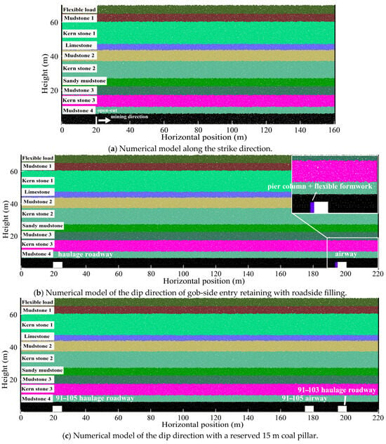
Figure 2.
Numeric model.
- (1)
- The strata are horizontal and the thickness of rock layers is stable.
- (2)
- In the model, the “pier column + flexible formwork” structure is represented by columns with equivalent width and load-bearing capacity, which can accommodate prescribed deformations.
- (3)
- Based on the burial depth and the average bulk density of the overlying strata, an additional overlying stratum is added to the top of each model to apply a gravity load of 12.50 MPa.
- (4)
- Fixed boundaries are applied to both sides of the models.
3.1.2. Parameter Calibration
The parallel bond model is used as the constitutive model for the rock mass material in each layer, while the smooth joint model is employed to represent the joints between rock strata.
Since the mechanical parameters in the PFC discrete element model differ from those of real rocks, it is necessary to establish an equivalence between the discrete element parameters and real-world mechanical properties. The main corresponding real-world mechanical parameters are shown in Table 1, including the following: Tension Strength, Compressive Strength, Elastic Modulus, and Poisson Ratio. The implementation process is as follows:
- (1)
- Mechanical parameters of real rock masses were obtained through laboratory tests, mainly including the parameters in Table 1: Tension Strength, Compressive Strength, Elastic Modulus, and Poisson Ratio.
- (2)
- Based on the known macroscopic mechanical parameters, discrete element parameters (mesoscopic mechanical parameters) were preliminarily estimated using formulas in reference [,,], including Effective Modulus, Normal-to-Shear Stiffness Ratio, Parallel Bond Effective Modulus, Parallel Bond Normal-To-Shear Stiffness Ratio, Tensile Strength, Cohesion, and Friction Angle.
- (3)
- The estimated discrete element parameters were input into the PFC rock mass model to simulate uniaxial tensile and compressive tests. The simulated results of Tension Strength, Compressive Strength, Elastic Modulus, and Poisson Ratio were compared with laboratory data, and the discrete element parameters were iteratively adjusted until the simulated values aligned with the experimental results. We considered errors within 10% between the simulated Tension Strength, Compressive Strength, Elastic Modulus, and Poisson Ratio and the laboratory data to be acceptable for validation.
A comparison of loaded stress–strain curves and damage patterns are shown in Figure 3. The finalized mesoscopic parameters for the coal and rock strata are presented in Table 3.
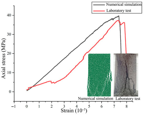
Figure 3.
Comparison of loaded stress–strain curves and damage patterns.

Table 3.
Mesoscopic mechanical parameters.
3.2. Result and Discussion
3.2.1. Overlying Strata Failure Law
To investigate the fracture and collapse behavior of the overlying strata during the mining process, the simulation results of goaf overburden caving at different mining distances are shown in Figure 4. Based on the simulation results, the relationship between the heights of bed separation fractures and breakage fractures and the mining distance was analyzed, as shown in Figure 5. The results indicate that before the working face advances 40 m, Mudstone 4 collapses synchronously with mining. When the mining reaches 40 m (Figure 4a), the initial collapse occurs in Kern Stone 3, Mudstone 3, and Sandy Mudstone. These three strata subsequently undergo periodic collapse at intervals of approximately 15 m. When mining distance reaches 75 m, the first fractures appear in Kern Stone 2 and the two overlying layers, followed by collapse at 90 m. Thereafter, the strata below Kern Stone 1 undergo deformation and failure in response to the collapse of Kern Stone 3. Once the working face advances to 105 m, the overlying strata begin to exhibit a stable pattern of periodic failure. Based on the analysis and key stratum theory [,,], Kern Stone 3 and Kern Stone 2 are identified as the first and second subordinate key strata, respectively, while Kern Stone 1 is recognized as the primary key stratum within 140 m above the coal seam. The first weighting interval of the working face is 40 m, and the periodic weighting interval is approximately 14 m. After the working face has advanced 105 m, the overlying strata begin to exhibit a stable pattern of periodic failure.
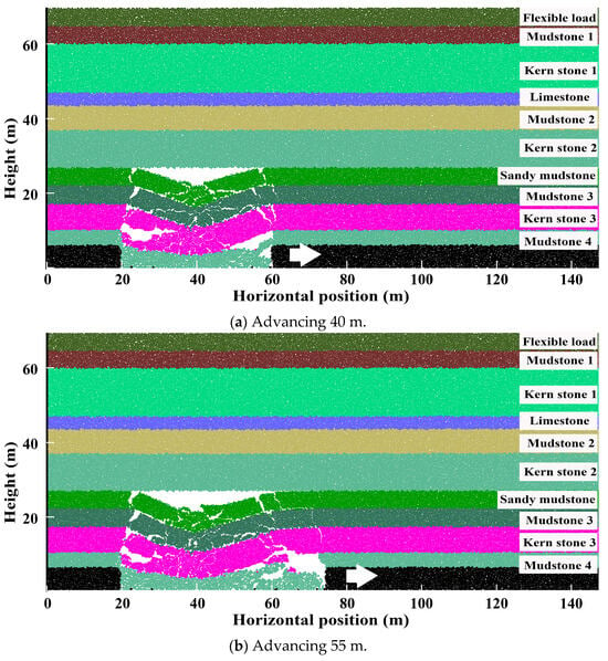
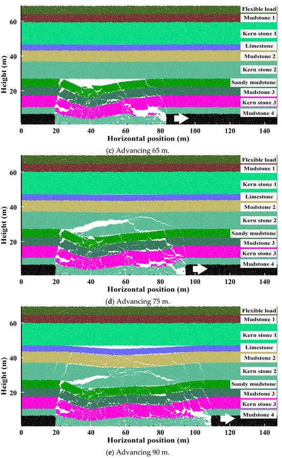
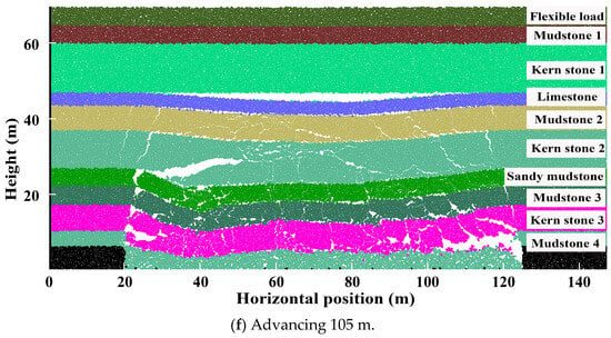
Figure 4.
Overlying strata failure during the mining process.
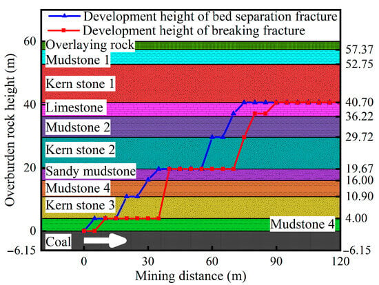
Figure 5.
The height of separation fractures and breaking fracture during the mining process.
Mine pressure monitoring at the working face indicates a first weighting interval of 36 m and a periodic weighting interval of 14 m. The numerical simulation results are in close agreement with these observations, demonstrating the accuracy of the meso–macro parameter mapping in the model and confirming its effectiveness in reproducing the real-world behavior of the overlying strata.
3.2.2. Characteristics of Fracture Development in Strike Direction
Fractures serve as the primary pathways for gas migration. To investigate their development and spatial distribution, the fracture patterns in the overlying strata were examined through visual analysis. Since the failure of the overlying strata exhibits a stable periodic pattern after the working face advances 105 m, the fracture characteristics at this mining distance were selected for detailed analysis, as shown in Figure 6. The red lines in the figure represent breaking fractures caused by the failure of overlying strata during the mining process. The results show that the overlying strata fractures are primarily concentrated within a trapezoidal zone extending approximately 40.7 m above the coal roof. The bottom-side angle of the open-cut is 82°, and that of the working face is 75°, indicating that the height of the gas-conducting fracture zone is 40.7 m. Further analysis reveals that the rock strata within 14.4 m above the roof are severely damaged and the fractures are extremely developed. The degree of damage to some rock strata between 14.4 m and 40.7 m is relatively low, indicating a relatively small influence from mining. Based on the extent of rock failure, it can be concluded that the falling zone ranges from 0 to 14.4 m, and the fracture zone extends from 14.4 to 40.7 m.
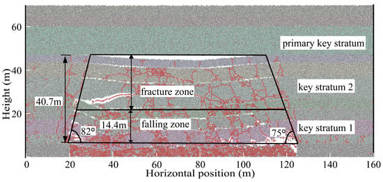
Figure 6.
The fracture development characteristics of the working face after mining 105 m along the strike of the working face.
3.2.3. Characteristics of Fracture Development in Dip Direction
The gob-side support method using filling structures affects the failure modes of the overlying strata along the dip direction, particularly the rotation, subsidence, fracturing, and collapse of the lateral roof above the retaining roadway. Therefore, numerical simulation were conducted to analyze the failure patterns of overlying strata under gob-side entry retaining with roadside filling and traditional coal pillar retaining conditions. The fracture distribution was zoned, as shown in Figure 7.
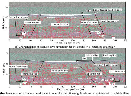
Figure 7.
Characteristics of fracture development in dip direction of working face.
In general, the ranges of the caving zone and the fracture zone are consistent under both filling and non-pillar conditions. The caving zone extends from 0 to 14.4 m, and the fracture zone extends from 14.4 to 40.7 m, which is consistent with the results in Section 3.2.2. Comparative analysis shows that under traditional coal pillar conditions (Figure 7a), the overall fracture distribution is symmetrical. Under gob-side entry retaining with roadside filling (Figure 7b), the side without entry retaining exhibits a pattern similar to that of the traditional condition. Both exhibit similar distribution characteristics in the lateral fracture area and separation zone, with a collapse angle of 76°. The primary difference between the two lies in the roadway-retaining side. Under roadside filling conditions, the fracture distribution of the overlying strata on this side is more complex. A moderately fractured zone exists between the well-developed separation zone and the poorly developed lateral fracture area. This occurs because under traditional coal pillar conditions, the overlying strata breaks and completely collapses with the coal pillar as the fulcrum. In contrast, under gob-side entry retaining conditions with roadside filling, the roadway roof breaks at the coal-side fulcrum outside the roadway, but the filling body restricts roof displacement, thus preventing collapse. As a result, collapse initiates at the filling body instead. The area between the breaking line and the collapse line is defined as the secondary breaking area. The secondary breaking area is an inverted trapezoid, with a narrow lower part and a wider upper part. The breaking angle is equal to the collapse angle on the non-entry-retaining side, both measuring 76°, and the collapse angle on the roadway-retaining side is 52°.
In addition, under the condition of gob-side entry retaining with roadside filling, changes in rock damage and the formation of the secondary breaking zone increase the span of the separation zone from 24 m to 30 m compared to traditional coal pillar conditions. The larger span of the separation zone and the smaller collapse angle jointly result in a larger space of the separation zone. This result shows that the roadside filling body can delay the subsidence rate of the overlying strata, expand the range of the separation zone and cause it to shift toward the goaf.
The formation of a secondary breaking zone above the backfill, as well as the expansion of the separation zone span and the reduction in the caving angle on the side of gob-side entry retaining with roadside filling, are considered unique characteristics under the conditions of gob-side entry retaining with roadside filling. The specific numerical variations should be determined according to the actual conditions of the mine.
3.2.4. Spatial Distribution of Gas Migration
The voids formed by fractures are the primary spaces for gas migration and accumulation. To further investigate the spatial distribution of gas migration in the goaf under gob-side entry retaining with roadside filling conditions, a voidage visualization analysis was conducted based on Figure 7b to obtain Figure 8. The results show that under gob-side entry retaining with roadside filling conditions, the void between the two collapse lines is low in the middle and high on both sides, implying a higher fracture distribution in this area. The high-voidage areas on both sides serve as the primary pathways for gas migration. Driven by buoyancy, gas rises and migrates along these zones, eventually accumulating in the high-porosity zone above the goaf. Combined with the ‘O’-shaped ring theory [], the gas migration and enrichment zones illustrated in Figure 8 can be identified. In the secondary breaking area—located between the collapse line and the secondary breaking line—the voidage is higher than that of the original rock area but lower than that of the gas migration zone, resulting in limited gas flow capacity.
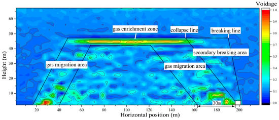
Figure 8.
Voids distribution characteristics in the dip direction of working face under gob-side entry retaining with roadside filling conditions.
3.3. Field Test of Overlying Strata Fractures
To further verify the correlation between the development of overlying strata fractures obtained from numerical simulation and the field conditions, peep boreholes were arranged in the working face retaining entry to investigate fracture development in the separation zone and secondary breaking area above the entry, as shown in Figure 9 (where the length represents the drilling footage). The peep results indicate that the degree of fracture development in the secondary breaking area is less extensive than in the separation zone. Only a small number of fractures observed below the 15 m roof stratum, and the borehole wall remains largely intact above this depth, with only a few isolated fractures. In contrast, in the separation zone, fractures are highly developed below 15 m, and the borehole wall is broken. Numerous fractures also occur in the strata above 15 m, with the degree of fracture development decreasing with increasing height.
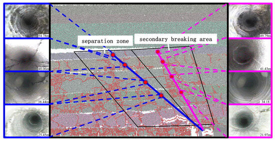
Figure 9.
Arrangement of boreholes for overlying strata peering and screenshots of typical positions.
4. The Study on Gas Control Technology of High Gas-Drainage Roadway
4.1. Theoretical Analysis of High Gas-Drainage Roadway Layout Range
4.1.1. Determination of Vertical Position Range of High Gas-Drainage Roadway
The high gas-drainage roadway should be located within the fracture zone. On one hand, the fracture zone is less affected by mining-induced stress, making the roadway more stable and less prone to damage. On the other hand, the fractures within this zone are well developed, allowing for gas accumulation and enabling the stable extraction of high-concentration gas [].
The vertical distance between high gas-drainage roadway and coal roof can be calculated using the following formula:
where is the height of the falling zone, m; is the coal mining height, m; is the height of the gas conductive fracture zone.
According to the numerical simulation results of overlying strata failure, the height of the falling zone in the 91–105 working face is 14.4 m above the coal seam roof, the height of the gas-conductive fracture zone is 40.7 m, and the mining height is 6.15 m. Therefore, the vertical distance from the high gas-drainage roadway to the coal seam roof should satisfy the following condition:
4.1.2. Determination of Horizontal Position Range of High Gas-Drainage Roadway
In the horizontal direction, the high gas-drainage roadway should be positioned on the side of the return air roadway and located within the ‘O’-shaped ring separation zone [,]. The horizontal distance formula between the high gas-drainage roadway and the return air roadway should satisfy the following formula:
where H is the vertical height of the high gas-drainage roadway from the coal roof, m; β is the collapse angle of overlying strata, °.
To ensure that the high gas-drainage roadway is located within the gas conductive fracture zone while avoiding the compaction area, the horizontal distance between the high-level gas drainage roadway and the return air roadway should also satisfy the following condition:
where X is the length of the working face in the dip direction, m.
Under gob-side entry retaining with roadside filling, the collapse angle of the overlying strata decreases compared to that under traditional coal pillar conditions, with a collapse angle of β = 52°. The length of the working face in the dip direction is 283 m. Accordingly, the horizontal distance S between the high gas-drainage roadway and the return air roadway should satisfy the following condition:
4.2. Numerical Simulation
4.2.1. Numerical Model
Based on the field conditions of the 91–105 working face at Wangzhuang Coal Mine, a geometric model was established in Fluent v.2022. Goaf dimensions are 500 m × 283 m × 50 m, and all roadway dimensions are 5.5 m in width and 3.6 m in height. The haulage roadway and the airway serve as intake air roadways, introducing fresh airflow, while the reserved roadway within the goaf functions as the return air roadway. The intake airflow volume is 2400 m3/min for the haulage roadway and 600 m3/min for the airway.
Due to the complex underground conditions in the real environment and the complexity of our research content, it is necessary to make idealized assumptions about some conditions in the model. The main assumptions include the following:
- (1)
- As the gas flotation phenomenon is considered, and buoyancy is caused by pressure differences, a gravitational field must be added to the model.
- (2)
- The gas in the goaf is an ideal gas and can be compressed during the study.
- (3)
- Since the effect of the temperature field is not studied, the temperature in the model is assumed to be constant.
- (4)
- The porous medium characteristics of the goaf remain isotropic.
- (5)
- The gas flow state in the goaf is stable, assumed to be turbulent, and the gas migration process conforms to Darcy’s law.
- (6)
- The gas emission sources are the goaf, which are uniformly distributed in the fractured zone and caving zone of the goaf.
- (7)
- The air entering the model contains 79% nitrogen and 21% oxygen, without carbon dioxide or gas.
- (8)
- The influence of various underground devices and equipment on airflow migration in roadways is ignored. The transportation roadway, air roadway, gob-side entry retaining, and mining face are all regarded as cuboid channels with smooth surfaces, assuming that the gas flow within the channels belongs to turbulent flow.
Through theoretical analysis, the horizontal position of the high gas-drainage roadway ranges from 14.8 to 94.3 m away from the return air roadway. Accordingly, six horizontal distances—15 m, 30 m, 45 m, 60 m, 75 m, and 90 m—were selected for numerical simulation analysis. The vertical position of the high gas-drainage roadway ranges from 20.5 to 40.7 m. Thus, four vertical heights are selected for simulation: 20 m, the middle position of the fracture zone at 28 m, 35 m, and 40 m. The numerical model of high gas-drainage roadway in the 91–105 working face is shown in Figure 10.
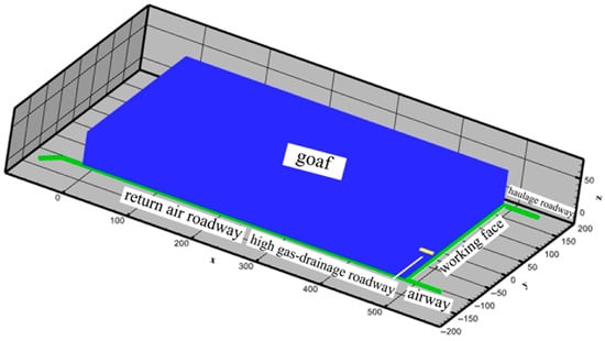
Figure 10.
Numerical model of high gas-drainage roadway extraction.
4.2.2. Parameter Setting
Based on the actual conditions of the 91–105 working face, the model solution parameters were set. The goaf voidage was coupled with the voidage distribution obtained from the PFC numerical simulation. The entrances of the haulage roadway and airway were set as velocity inlets, with an inlet velocity of 2.02 m/s for the haulage roadway and 0.50 m/s for the airway. The outlet of the gob-side entry retaining was defined as a free outflow boundary. The drainage mixture volume for the high gas-drainage roadway is 500 m3/min. In the model, the gas source terms for the coal wall and fallen coal are 1.82 × 10⁻⁵ kg/(m3·s), and the gas source term for the goaf is 4.6 × 10⁻⁸ kg/(m3·s).
4.3. Result and Discussion
4.3.1. Gas Concentration Distribution Characteristics in the Goaf Under High Gas-Drainage Roadway Extraction Conditions
Figure 11 illustrates the gas concentration distribution in the goaf when the horizontal distance between the high gas-drainage roadway and the return air roadway is 30 m, and the vertical distance is 28 m. As shown in Figure 11a, the gas concentration distribution exhibits an “O”-shaped pattern corresponding to the ‘O’-shaped ring formed by the goaf collapse. At the periphery of the goaf, high voidage results in significant air leakage and low gas concentration. Toward the deeper part of the goaf, compaction intensifies, leading to reduced voidage and increased gas concentration. The gas concentration in the compaction area at the center of the goaf is relatively high, reaching as high as 75%.
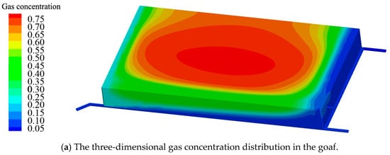

Figure 11.
Gas distribution map.
As shown in Figure 11b,c, methane, being approximately half as dense as air, exhibits buoyancy under the influence of gravity, resulting in upward migration along fractures. Gas migration is more pronounced around the perimeter of the goaf than in the central region, due to the higher fracture density at the edges compared to the interior. As clearly shown in Figure 11b, the gas concentration distribution along the strike section is characterized by high concentrations in the middle and upper parts, and low concentrations on both sides and in the lower part.
Due to the drainage effect of the high gas-drainage roadway, the gas concentration near the high gas-drainage roadway side is significantly lower than that on the intake side. In the central region of the goaf, the gas concentration on the intake side reaches as high as 71%, while on the return side, it reaches as high as 42%.
As shown in Figure 11c, it can be seen that, in the dip section, due to air leakage in the goaf, the gas concentration in the lower part of the goaf is low, forming an arc-shaped distribution. Compared to the intake side, the gas concentration on the return side, between the high gas-drainage roadway and the return air roadway, is significantly reduced due to the high gas-drainage roadway, indicating a notable gas drainage effect.
4.3.2. Extraction Effect at Different Horizontal Positions
Figure 12 shows the variation in gas concentration in the high gas-drainage roadway and return air flow when the high gas-drainage roadway is 28 m away from the coal seam roof and at different horizontal distances from the return air roadway. As shown in Figure 12, it can be seen that when the vertical distance of the high gas-drainage roadway is fixed and the horizontal distance increases from 15 m to 90 m, the gas concentration in the high gas-drainage roadway initially increases and then decreases, reaching a peak at 30 m. This indicates that when the horizontal distance from the return air roadway is 15 m, the proximity to the return air roadway, combined with the negative pressure effect of the high gas-drainage roadway, causes a portion of the fresh airflow in the gob-side entry retaining to be drawn toward the high gas-drainage roadway, thereby reducing the local gas concentration. Meanwhile, the short horizontal distance also limits the drainage range of high-concentration gas. When the horizontal distance is 30 m, the gas concentration in the high gas-drainage roadway reaches its maximum value of 4.32%. At this position, the roadway can extract a large volume of high-concentration gas. As the horizontal distance increases from 45 m to 90 m, the extracted gas concentration gradually decreases. This trend indicates that with increasing horizontal distance, the high gas-drainage roadway progressively approaches the compaction area of the ‘O’-shaped ring formed by mining-induced fractures. As a result, the difficulty of extracting high-concentration gas increases, leading to a reduction in extraction efficiency.
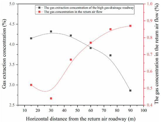
Figure 12.
The gas extraction effects of the high gas-drainage roadway at different horizontal positions.
As shown in Figure 12, when the horizontal distance increases from 15 m to 90 m, the gas concentration in the return airflow of the gob-side entry retaining initially decreases and then increases, exhibiting a trend opposite to that of the extraction concentration. The maximum gas concentration in the return airflow reaches 0.87%, approaching 1%, while the minimum concentration occurs at 30 m, reaching as low as 0.44%.
The findings indicate that positioning the high gas-drainage roadway 30 m horizontally from the return air roadway yields optimal performance. At this distance, the gas extraction concentration reaches a peak of 4.32%, while return airflow gas concentration is minimized to 0.44%, demonstrating effective gas control. Therefore, it is recommended that the high gas-drainage roadway be located 30 m horizontally from the return air roadway.
4.3.3. Extraction Effects at Different Vertical Positions
Figure 13 illustrates the variation in gas concentration within the high gas-drainage roadway and return airflow when the horizontal distance from the return air roadway is fixed at 30 m, and the vertical distances from the coal roof are 20 m, 28 m, 35 m, and 40 m. As shown in Figure 13, it can be seen that the gas concentration in the high gas-drainage roadway initially increases and then decreases, with increasing vertical height. This trend is attributed to the fact that at a vertical height of 20 m, the high gas-drainage roadway is located in the lower part of the compaction area within the ‘O’-shaped ring formed by mining-induced fractures. At this position, less gas can be extracted from the upper part of the fracture zone, but due to its proximity to the working face, it is capable of extracting more gas directly from the working face. However, its closeness to the return air roadway may result in air leakage from the return air roadway, which reduces both the gas concentration and the net gas flow in the high gas-drainage roadway.
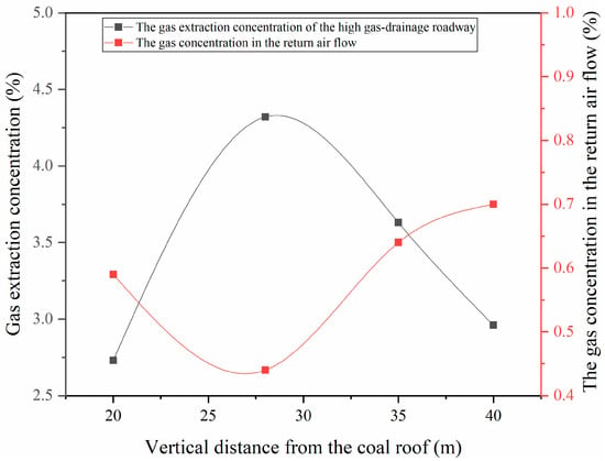
Figure 13.
The gas extraction effects of the high gas-drainage roadway at different vertical positions.
At a vertical height of 28 m, the high gas-drainage roadway is located in the middle of the ‘O’-shaped ring fracture zone, enabling efficient gas extraction from this region and resulting in the highest gas concentration of 4.32%. As the vertical height increases to 35 m and 40 m, the high gas-drainage roadway moves farther from the working face and shifts into the upper portion of the ‘O’-shaped ring fracture zone. Although the lower density of gas promotes upward migration, enabling the extraction of gas rising from the goaf, the increased distance from the working face introduces greater resistance to upward flow. This hinders gas migration and makes extraction more difficult, resulting in a reduced gas concentration in the high gas-drainage roadway.
As shown in Figure 13, when the vertical distance varies from 20 m to 45 m, the gas concentration in the return airflow of the gob-side entry retaining initially decreases and then increases, exhibiting a trend opposite to that of the extraction concentration. The maximum gas concentration in the return airflow reaches 0.75%, while the minimum value of 0.64% occurs when the high gas-drainage roadway is located 28 m above the coal roof.
When the high gas-drainage roadway is located 28 m from the coal roof, the gas extraction concentration exceeds 3.6%, while the gas concentration in the return airflow remains below 0.64%. This configuration yields the optimal extraction performance. Therefore, it is recommended that the high gas-drainage roadway be positioned at a vertical distance of 28 m from the coal roof.
4.4. Field Test of High Gas-Drainage Roadway
4.4.1. The Layout of the High Gas-Drainage Roadway
Based on the simulation results, the optimal location for the high gas-drainage roadway was determined to be at a height of 28 m vertically above the coal roof and 30 m horizontally from the return air roadway. The further analysis of the field conditions indicates that the stratum at this position corresponds to kern stone 2, with an average thickness of 10 m. This stratum is generally stable and exhibits moderate hardness. Borehole sampling reveals well-developed fractures, providing favorable geological conditions for the construction of the high gas-drainage roadway. The layout of the high gas-drainage roadway is illustrated in Figure 14. Unlike the 8105 working face, where the roadway was placed based on fracture development characteristics under coal pillar conditions, the high gas-drainage roadway in the 91–105 working face has been shifted 10 m toward the goaf. It is now located 28 m above the coal roof and 20 m horizontally from the return air roadway.
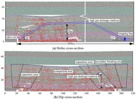
Figure 14.
Layout position of the high gas-drainage roadway.
The high gas-drainage roadway in the field has a total tunneling length of 2868 m and a designed cross-section of 3.0 m × 5.2 m. Excavation begins from the main return air roadway toward the open-cut. First, the roadway is driven horizontally along the coal seam to the stopping line of the 91–105 working face. Then, it ascends at an incline of 22° until it reaches a position 28 m above the coal seam roof. Once this elevation is attained, tunneling continues along the designated stratum. When the excavation has reached a point 50 m from the open cut on the 91–105 working face, the tunnel then inclines downward at an angle of 28° to ultimately connect with the open cut. Upon completion of the entire roadway excavation, reinforced concrete is poured at the entrance of the high gas-drainage roadway to form a sealed closure. The sealing trench has a depth of 500 mm and a designed wall thickness of 4 m. Two D1016 mm gas pipelines are embedded within the sealing wall: one dedicated to gas extraction and the other reserved for maintenance access.
4.4.2. Extraction Effect
To evaluate the extraction performance of the high gas-drainage roadway, gas extraction data were monitored and plotted into statistical graphs, as shown in Figure 15. These results were compared with historical data from the 8105 working face. The gas extraction concentration in the high gas-drainage roadway of the 8105 working face ranged from 2.87% to 4.08%, with an average value of 3.26%. The net gas flow ranged from 11.90 m3/min to 17.92 m3/min, with an average of 14.63 m3/min.
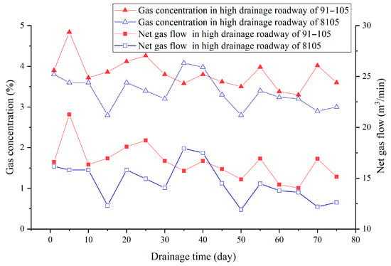
Figure 15.
Monitoring data from the high gas-drainage roadway.
The gas extraction concentration in the high gas-drainage roadway of the 91–105 working face remained relatively stable, ranging from 3.30% to 4.84%, with an average value of 3.97%. The net gas flow ranged from 14.03 m3/min to 21.25 m3/min, with an average value of 17.25 m3/min. Compared with the 8105 working face, the extraction concentration increased by 22%, and the net gas flow increased by 18%, indicating a significant improvement. These results demonstrate that the high gas-drainage roadway, designed based on the evolution law of the overlying strata fracture under gob-side entry retaining with roadside filling condition, played a good role in the gas extraction process in the working face, effectively extracting enriched gas from the goaf. The location of the high gas-drainage roadway is therefore reasonable.
5. Conclusions
- (1)
- Under these geological conditions and mining conditions, the first weighting interval of the 91–105 working face is 40 m, and the periodic weighting interval is 14 m. After 105 m of mining, the overlying strata collapse to the primary key stratum, after which a stable periodic behavior is observed. The height of the falling zone is 14.4 m, and the height of the gas-conducting fracture zone is 40.7 m. In the strike direction, the collapse angle on the working face side is 75 °, while that on the open-cut side is 82°.
- (2)
- In the dip direction, compared to the condition with reserved coal pillars, gob-side entry retaining with roadside filling forms an inverted trapezoidal secondary breaking area above the retained entry. This leads to an increase in the span of the separation zone to 30 m and a reduction in the collapse angle to 52°, thereby shifting the primary gas migration space—the separation zone—toward the goaf.
- (3)
- The optimal position for the high gas-drainage roadway is determined to be 28 m vertically from the coal roof and 30 m horizontally from the return air roadway. Compared to the 8105 working face, the newly positioned high gas-drainage roadway is 10 m closer to the goaf. After the repositioning, the gas concentration in the high gas-drainage roadway increased by 22%, and the net gas flow increased by 18%, indicating a significant improvement in gas extraction efficiency.
Author Contributions
Conceptualization, Y.Y., Z.L. (Zhigang Li), H.G. and Z.L. (Zetian Li); methodology, Y.Y., Z.L. (Zetian Li) and Z.L. (Zhangyang Li); software, Y.Y., H.L. and A.L.; validation, Y.Y. and Z.L. (Zetian Li); formal analysis, Y.Y.; investigation, Y.Y.; resources, Z.L. (Zhigang Li); data curation, Y.Y.; writing—original draft preparation, Y.Y.; writing—review and editing, H.G., Z.L. (Zetian Li) and Z.L. (Zhigang Li); visualization, Y.Y.; supervision, H.G. and Z.L. (Zhigang Li); project administration, Z.L. (Zhigang Li); funding acquisition, Z.L. (Zhigang Li). All authors have read and agreed to the published version of the manuscript.
Funding
This research was funded by National Natural Science Foundation of China (Grant No. U1810103, No. 52304246), Shanxi Provincial Basic Research Program (Grant No. 202403021211210, No. 202203021212277), and Shanxi Scholarship Council of China (No. 2022-054).
Institutional Review Board Statement
Not applicable.
Informed Consent Statement
Not applicable.
Data Availability Statement
The original contributions presented in the study are included in the article, and further inquiries can be directed to the corresponding author.
Conflicts of Interest
The authors declare that the research was conducted in the absence of any commercial or financial relationships that could be construed as a potential conflict of interest.
References
- Li, D.; Cheng, Y. Evaluation of Gas Control Ability of a Coal and Gas Outburst Mine. Energy Sources Part A-Recovery Util. Environ. Eff. 2014, 36, 2401–2409. [Google Scholar] [CrossRef]
- Tian, H.; Li, Z.H.; Liu, Z.; Yin, S.; Niu, Y.; Zhang, Q.C.; Chen, D. Visual characterization of coal gas desorption using infrared radiation. Energy 2024, 289, 130052. [Google Scholar] [CrossRef]
- Guo, H.J.; Yu, Y.J.; Wang, K.; Yang, Z.; Wang, L.; Xu, C. Kinetic characteristics of desorption and diffusion in raw coal and tectonic coal and their influence on coal and gas outburst. Fuel 2023, 343, 127883. [Google Scholar] [CrossRef]
- Hu, C.W.; Wang, J.J.; Zhang, F.; Hu, B.; Zhang, J.S. The Coordinated Mining Technology of Coal and Gas in Outburst Coal Seams. Shock Vib. 2024, 11, 15–20. [Google Scholar] [CrossRef]
- Kumar, P.; Mishra, D.P.; Panigrahi, D.C.; Sahu, P. Numerical studies of ventilation effect on methane layering behaviour in underground coal mines. Curr. Sci. 2017, 112, 1873–1881. [Google Scholar] [CrossRef]
- Bao, R.Y.; Shi, B.; Zhang, C. Research and Application of ?Concentric Ring? Reinforcement and Sealing Technology for Gas Drainage Boreholes in Soft-Coal Seams. ACS Omega 2022, 7, 34763–34769. [Google Scholar] [CrossRef] [PubMed]
- Chai, J.M. Study on Gas Control in Goaf of High Gas Coal Seam: A Case Study of Tingnan Coal Mine, China. Geofluids 2022, 2022, 5262173. [Google Scholar] [CrossRef]
- Xu, C.; Sun, H.; Wang, K.; Qin, L.; Guo, C.; Wen, Z. Effect of low-level roadway tunneling on gas drainage for underlying coal seam mining: Numerical analysis and field application. Greenh. Gases Sci. Technol. 2021, 11, 780–794. [Google Scholar] [CrossRef]
- Zhang, H.J.; Shen, M.L.; Huo, Z.G.; Zhang, Y.B.; Shu, L.Y.; Li, Y. Research on Gas Drainage Pipeline Leakage Detection and Localization Based on the Pressure Gradient Method. Processes 2024, 12, 1590. [Google Scholar] [CrossRef]
- Xu, C.; Wang, K.; Li, X.M.; Yuan, L.; Zhao, C.Y.; Guo, H.J. Collaborative gas drainage technology of high and low level roadways in highly-gassy coal seam mining. Fuel 2022, 323, 124325. [Google Scholar] [CrossRef]
- Guo, S.; Hu, G.; Zhu, J.; Xu, J.; Qin, W.; Yang, N. Intelligent prediction method for roof gas drainage roadway layout. Coal Sci. Technol. 2024, 52, 203–213. [Google Scholar] [CrossRef]
- Kang, J.; Wu, J.; Li, X.; Li, W.; Zhu, J.; Zhang, X. Gas distribution in goaf with high drainage roadway and buried pipe drainage. J. Min. Saf. Eng. 2021, 38, 191–198. [Google Scholar] [CrossRef]
- Yu, Q.-X.; Cheng, Y.-P.; Jiang, C.-L.; Zhou, S.-N. Principles and applications of exploitation of coal and pressure relief gas in thick and high-gas seams. J. China Univ. Min. Technol. 2004, 33, 127–131. [Google Scholar]
- Zhang, Q.; Zheng, T.; Wang, X.; Fang, Z. Multi-Source Information Monitoring Test of Fractured Rock Mass Destruction Characteristics and Sensitivity Analysis of Precursor Phenomena. Energies 2022, 15, 538. [Google Scholar] [CrossRef]
- Li, S.; Liu, L.; Zhao, P.; Lin, H.; Xu, P.; Zhuo, R. Analysis and application of fracture evolution law of overburden compacted area on fully-mechanized mining face under multiple factors. Coal Sci. Technol. 2021, 50, 95–104. [Google Scholar]
- Yuan, L.; Guo, H.; Shen, B.-T.; Qu, Q.-D.; Xue, J.-H. Circular overlying zone at longwall panel for efficient methane capture of mutiple coal seams with low permeability. J. China Coal Soc. 2011, 36, 357–365. [Google Scholar]
- Li, S.-G.; Lin, H.-F.; Zhao, P.-X.; Xiao, P.; Pan, H.-Y. Dynamic evolution of mining fissure elliptic paraboloid zone and extraction coal and gas. J. China Coal Soc. 2014, 39, 1455–1462. [Google Scholar] [CrossRef]
- Lin, H.-F.; Li, S.-G.; Cheng, L.-H.; Wang, H.-S. Experimental analysis of dynamic evolution model of mining-induced fissure zone in overlying strata. Caikuang Yu Anquan Gongcheng Xuebao/J. Min. Saf. Eng. 2011, 28, 298–303. [Google Scholar]
- Zhang, S.; Shen, B.; Li, Y.; Zhou, S. Modeling Rock Fracture Propagation and Water Inrush Mechanisms in Underground Coal Mine. Geofluids 2019, 2019, 1796965. [Google Scholar] [CrossRef]
- Sakhno, I.; Zuievska, N.; Xiao, L.; Zuievskyi, Y.; Sakhno, S.; Semchuk, R. Prediction of Water Inrush Hazard in Fully Mechanized Coal Seams’ Mining Under Aquifers by Numerical Simulation in ANSYS Software. Appl. Sci. 2025, 15, 4302. [Google Scholar] [CrossRef]
- Jiang, D.; Tang, Y.; Huang, W.; Hou, K.; Luo, Y.; Liu, J. Research on the Height of the Water-Conducting Fracture Zone in Fully Mechanized Top Coal Caving Face under Combined-Strata Structure. Sustainability 2022, 14, 13781. [Google Scholar] [CrossRef]
- Wang, X. Mechanism of pressure relief by advanced pre-splitting in gob-side entry retaining and arrangement principle of pre-splitting boreholes. J. Min. Saf. Eng. 2024, 41, 1125–1133. [Google Scholar] [CrossRef]
- Xu, X.; He, F.; Zhai, W.; Wang, D.; Li, X.; Song, J.; Zhang, Y. Pressure bearing and deformation of the surrounding rock-support body and control technology on the gangue side in gob side entry retaining by roof cutting. Chin. J. Rock Mech. Eng. 2024, 43, 439–453. [Google Scholar] [CrossRef]
- Liu, X.; Hua, X.; Liang, Y.; Li, C. Quantitative Research on Roof Deformation and Temporary Support Stiffness in Deep-Mine Gob-Side Entry Retaining by Roof Cutting. Appl. Sci. 2024, 14, 6520. [Google Scholar] [CrossRef]
- Hu, J.; Ma, Z.; Guo, P.; Hu, Y. Fracture evolution of the main roof in gob-side entry retaining by roof cutting of an inclined coal seam. Energy Explor. Exploit. 2023, 41, 1396–1414. [Google Scholar] [CrossRef]
- Liu, H.; Zhao, Y.; Ren, T.; Wang, F.; Li, Z. Characteristics of overburden failure and fracture development in gob of mining with gob-side entry formed by cutting roof. Zhongguo Kuangye Daxue Xuebao/J. China Univ. Min. Technol. 2022, 51, 77–89. [Google Scholar]
- Zhao, Y.; Yang, Y.; Wang, Z.; Gu, Q.; Wei, S.; Li, X.; Wang, C. Innovative Cut-and-Fill Mining Method for Controlled Surface Subsidence and Resourceful Utilization of Coal Gangue. Minerals 2025, 15, 146. [Google Scholar] [CrossRef]
- Chen, L.; Cheng, Z.; Wang, H.; Luo, X.; Xu, Z.; Dong, Y.; Li, W.; Wang, P.; Yu, H. Deformation and air leakage mechanism of gob-side entry retaining and multiple collaborative prevention and control technology in thick coal seam. Coal Sci. Technol. 2024, 52, 114–126. [Google Scholar] [CrossRef]
- Xu, C.; Wang, X.; Chen, D.; Wang, G.; Niu, Z.; Lu, H. Study on the Stability and Control of Gob-Side Entry Retaining in Paste Backfill Working Face. Appl. Sci. 2025, 15, 528. [Google Scholar] [CrossRef]
- Wang, Y.; Zhao, Z.; Zhang, W.; Wei, X.; Hui, Z. Deformation mechanism and control technology of gob-side entry retaining with roadside backfilling: A numerical analysis and field investigation. Geomech. Geophys. Geo-Energy Geo-Resour. 2024, 10, 175. [Google Scholar] [CrossRef]
- Cui, D.; Zhang, Y.; Zhang, S.; Wu, X.; Wang, Q.; Cui, B.; Zhu, D. Mechanical Mechanism of Surrounding Rock Failure and Stability Control for Gob-Side Entry Driving Near an Advancing Working Face. Energy Sci. Eng. 2025, 13, 2631–2646. [Google Scholar] [CrossRef]
- Gai, Q.; He, M.; Li, S.; Gao, Y. Study on strike failure characteristics of floor in a new type of pillarless gob-side entry retaining technology above confined water. Tunn. Undergr. Space Technol. 2025, 161, 106596. [Google Scholar] [CrossRef]
- Guo, J.; Yang, W.; Zhao, Y.; Zhang, W. Stability Analysis of a Mine Wall Based on Different Roof-Contact Filling Rates. Minerals 2024, 14, 673. [Google Scholar] [CrossRef]
- Sakhno, I.; Sakhno, S.; Skrzypkowski, K.; Isaienkov, O.; Zagórski, K.; Zagórska, A. Floor Heave Control in Gob-Side Entry Retaining by Pillarless Coal Mining with Anti-Shear Pile Technology. Appl. Sci. 2024, 14, 4992. [Google Scholar] [CrossRef]
- Małkowski, P.; Ostrowski, Ł.; Stasica, J. Modeling of Floor Heave in Underground Roadways in Dry and Waterlogged Conditions. Energies 2022, 15, 4340. [Google Scholar] [CrossRef]
- Manso, J.; Marcelino, J.; Caldeira, L. Effect of the clump size for bonded particle model on the uniaxial and tensile strength ratio of rock. Int. J. Rock Mech. Min. Sci. 2019, 114, 131–140. [Google Scholar] [CrossRef]
- Cho, N.; Martin, C.D.; Sego, D.C. A clumped particle model for rock. Int. J. Rock Mech. Min. Sci. 2007, 44, 997–1010. [Google Scholar] [CrossRef]
- Wu, M.-M.; Wang, G.; Wang, R.; Li, W.-X.; Chu, X.-Y. Space-time porosity distribution on overlying strata above a shallow seam. J. China Coal Soc. 2017, 42, 112–121. [Google Scholar] [CrossRef]
- Dou, L.; Cao, J.; Cao, A.; Cai, W.; Gong, S.; Ju, M.; Zhou, K.; Kan, J. Key strata of mining-induced seismicity in overburden rocks in coal mines and the energy-releasing mechanism of its fracture. J. China Coal Soc. 2025, 50, 180–192. [Google Scholar] [CrossRef]
- Zhao, B.; Guo, Y.; Sun, H.; Yang, X.; Wang, J.; Zhao, Y. Stability research on the water-resistant strata under mining in nearly shallow coal seam based on location of main key stratum. J. Min. Saf. Eng. 2022, 39, 653–662. [Google Scholar] [CrossRef]
- Li, B.; Liang, Y.; Zou, Q. Determination of working resistance based on movement type of the first subordinate key stratum in a fully mechanized face with large mining height. Energy Sci. Eng. 2019, 7, 777–798. [Google Scholar] [CrossRef]
- Li, W. Spatial evolution law of overlying strata stress zone in deep high-stress stoping and its influence on methane drainage roadway. J. Min. Saf. Eng. 2021, 38, 181–190. [Google Scholar] [CrossRef]
- Xiao, J.; Fan, S.; Lu, P.; Chen, Y.; Chen, F. Layout parameter optimization of highly-located drainage roadway along seam for controlling gas with pressure relief from close-distance methane-rich seam group. Caikuang Yu Anquan Gongcheng Xuebao/J. Min. Saf. Eng. 2016, 33, 564–570. [Google Scholar] [CrossRef]
- Zhao, P.; Kang, X.; Li, S.; Lin, H.; Gan, L.; An, X. Optimization of “hole-drift” collaborative drainage layout parameters and high efficient drainage in pressure relief gas migration area. Coal Sci. Technol. 2022, 50, 137–146. [Google Scholar] [CrossRef]
Disclaimer/Publisher’s Note: The statements, opinions and data contained in all publications are solely those of the individual author(s) and contributor(s) and not of MDPI and/or the editor(s). MDPI and/or the editor(s) disclaim responsibility for any injury to people or property resulting from any ideas, methods, instructions or products referred to in the content. |
© 2025 by the authors. Licensee MDPI, Basel, Switzerland. This article is an open access article distributed under the terms and conditions of the Creative Commons Attribution (CC BY) license (https://creativecommons.org/licenses/by/4.0/).