Article

Vibration Damage Analysis of Bottom Hole Assembly Under Axial Impact Based on Dynamic Analysis

1
School of Engineering and Technology, China University of Geosciences, Beijing 100083, China
2
CNOOC Research Institute Ltd., Beijing 100028, China
*
Author to whom correspondence should be addressed.
Appl. Sci. 2025, 15(13), 7388; https://doi.org/10.3390/app15137388
Submission received: 23 May 2025 / Revised: 21 June 2025 / Accepted: 27 June 2025 / Published: 30 June 2025

Abstract

Impact Drilling Technology is one of the most effective methods for enhancing the penetration rate and efficiency in hard rock formations. Downhole axial vibration impact tools can provide a stable impact load, but they also increase the complexity of the Bottom Hole Assembly (BHA) motion. Addressing the problem of vibration fatigue in the lower BHA when subjected to high-frequency impact stresses during impact drilling, this study utilizes finite-element impact modules and Design-Life fatigue analysis software to establish a nonlinear dynamic model of the drill string assembly under axial excitation. It investigates the influence patterns of control parameters, such as the impact energy and impact frequency, on BHA vibration damage and rock-breaking efficiency. The results show that the vibration characteristics of the BHA are significantly affected by the impact tool’s control parameters. Increasing the input impact energy intensifies the amplitude of alternating stress in the drill string system. Meanwhile, the equivalent stress fluctuation of the drill string tends to stabilize at high frequencies above 100 Hz, indicating that high-frequency impacts are beneficial for mitigating vibration damage and prolonging the service life of the BHA. This study provides a theoretical basis for reducing the drill string fatigue damage and optimizing the drilling parameters for an improved performance.

1. Introduction

Deep oil and gas reservoirs are predominantly characterized by low-permeability formations and an exceptionally high rock strength. The inherent complexities of drilling operations combined with harsh downhole conditions impose significant challenges to drill string reliability during drilling processes. During hydrocarbon exploration drilling, axial vibration impact drilling tools generate reciprocating impact loads under mud-driven actuation. The impact hammer transmits frequency-specific impact energy to the drill bit, achieving combined percussive-cutting rock fragmentation [1,2,3,4,5]. However, under high-speed rotary–percussive drilling operations, the Bottom Hole Assembly (BHA) experiences high-frequency cyclic impact loading—distinct from conventional rotary drilling. This induces periodic reciprocating vibrations in the drill string assembly, substantially amplifying the stress complexity in downhole configurations [6,7].
To further elucidate the dynamic behavior of drilling assemblies during percussive drilling, researchers have conducted extensive investigations: Guan [8] analyzed drill string displacement and vibration under varying Weight on Bit (WOB) and rotary speeds using a BHA motion simulation experimental apparatus. N.H. Dao et al. [9] modeled surface crack propagation in drill pipes during rotary drilling using 3D finite element analysis integrated with the Walker model, demonstrating the critical influence of axial forces on crack growth. Cui et al. [10] evaluated frequency-dependent fatigue damage in integrated vertical drilling and multi-dimensional vibration reduction systems under continuous hydraulic impactor loading and formation reaction forces. Zhang et al. [11] developed a finite element model for drill pipe joint fatigue life, identifying the stress concentration, residual stresses, and surface quality as significant factors influencing the drill string fatigue life. Li et al. [12] established a composite drill string fatigue life model, demonstrating through case studies that non-buckled drill strings exhibit a shorter fatigue life than buckled drill strings. T.A. Lemma et al. [13] implemented fuzzy systems to model the dimensionless strength factors of drill pipes, predicting the fatigue life using fuzzy systems and cumulative damage theory. The analysis revealed that the drill string fatigue life is highly sensitive to initial crack size measurement accuracy. Qiu et al. [14] formulated a dynamic model for push-the-bit rotary steerable drilling BHAs using Hamilton’s principle, calculating and analyzing dynamic characteristics including natural frequencies and dynamic stresses. The analysis indicated that peak stress correlates with the WOB and drilling rate. Mao et al. developed a BHA fatigue life prediction model based on drill string dynamics theory using the FEM, incorporating the initial crack defects. The results demonstrated that transverse vibration exceeds longitudinal vibration, with transverse vibration being the primary cause of BHA fatigue failure. Li et al. [15] conducted experiments using a mechanical rock-breaking test system under a combined impact and WOB loading, performing a comparative analysis of the torsional impact versus static pressure impact fragmentation on sandstone samples. The findings indicate that simultaneous pulsed torque and WOB application during PDC bit-cutting and friction processes significantly mitigates the bit stick–slip effect. A comparative analysis of red/yellow sandstone demonstrated that the torsional impact achieves a superior rate of penetration (ROP) enhancement when drilling experimental rock samples to equivalent depths.
The current research on the axial impact vibration characteristics of drill strings predominantly focuses on the influence of control parameters on the dynamic and static behavioral characteristics of drilling assemblies. In contrast, the relationship between the impact vibration characteristics and fatigue life requires further investigation. To systematically investigate the vibration propagation mechanisms of downhole impact tools and analyze the fatigue damage evolution under sustained impact loading, this study employs Miner’s linear cumulative damage theory, integrating drill string vibration governing equations with material S-N curves. First, the dynamic response of the BHA under a periodic impact is derived using the FEM, enabling a quantitative analysis of transient von Mises stress distribution and impact vibration characteristics of the BHA. Concurrently, load uncertainty is incorporated and fatigue analysis modules are utilized to analyze the damage accumulation distribution in the BHA under varying loading conditions (amplitude and frequency), predicting the serviceable cycle life of the drilling tools. This provides theoretical references for optimizing impact parameters, extending the drilling tool service life, and enhancing the drilling speed in field applications.

2. Impact Simulation Model

2.1. Basic Assumptions

The dynamic analysis of the downhole drill string system during drilling is highly complex, as it requires the coupling of the rock formation, drill bit, drill string, and borehole wall, which is a challenging task. Therefore, the downhole environment is appropriately simplified in this study and a substructuring method is employed to establish the dynamic model of the drill string system [16,17,18]. Since the focus of this paper is on the analysis of the longitudinal vibrations and dynamic stresses in the drill string induced by impact drilling operations, only the axial impact-induced longitudinal vibrations between the drill string and the rock formation are considered. The lateral, torsional, and coupled vibrations of the drill string system are not accounted for in this study. For the sake of convenience in the analysis, the following reasonable physical assumptions are made:
  • The impact force is converted into an equivalent periodic excitation acting on the drill bit;
  • The effect of drilling fluid on the drill string is neglected;
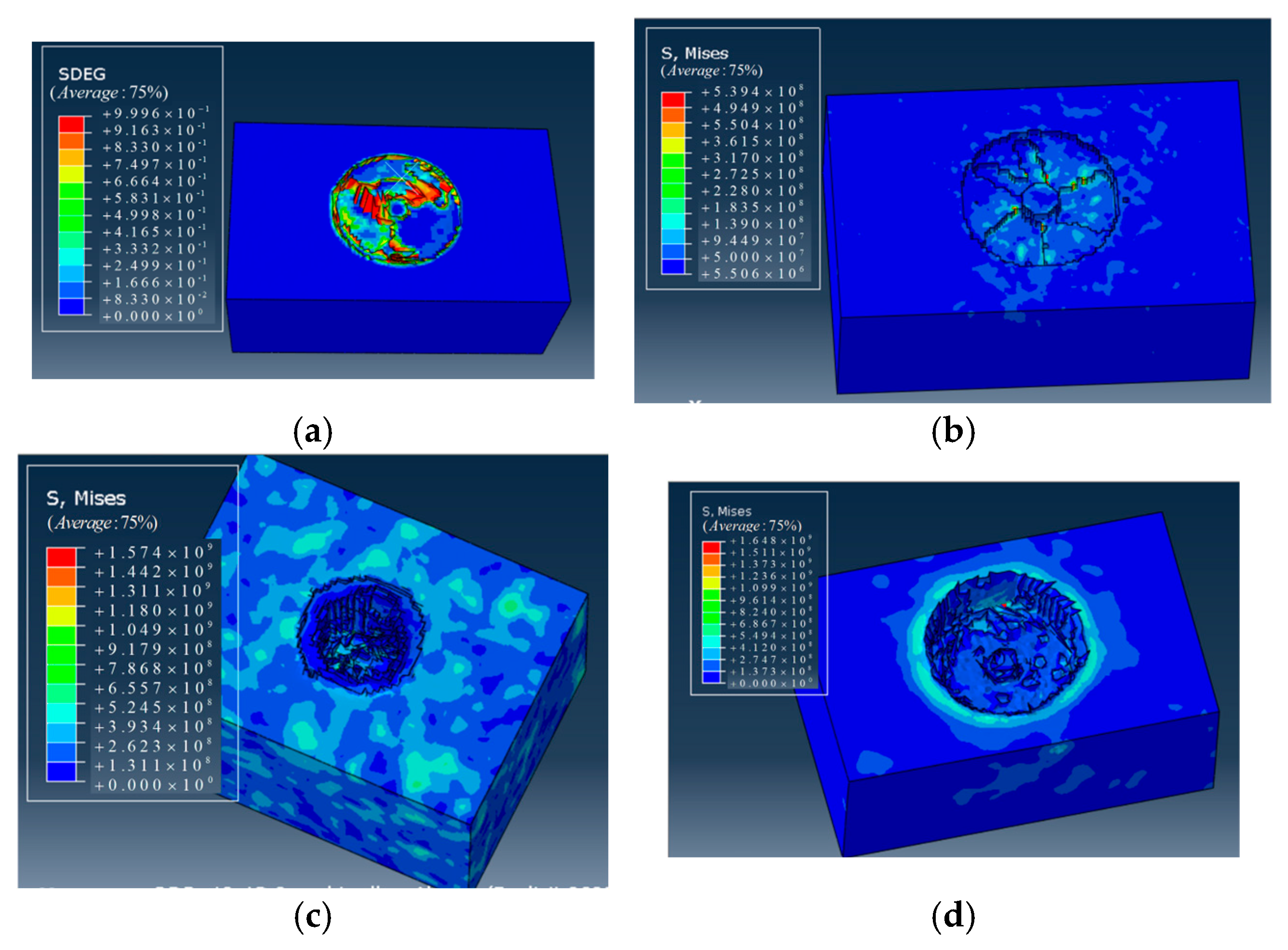
  • Rock damage and fragmentation are taken into account. If rock failure occurs, an element is removed from the mesh;
  • Initially, the borehole axis coincides with the drill string axis, and there exists an annular clearance between the borehole wall and the drill string. The borehole cross-section is assumed to be circular;
  • The borehole wall is set as an undeformable rigid body, while the BHA is modeled as an elastic beam element.

2.2. Geometric Models, Boundary Conditions, and Material Properties

2.2.1. Model Construction

Based on the working principle of the downhole axial impactor, a vertical wellbore section model of the percussive drilling assembly was established using the finite element software ABAQUS v.2024. The BHA configuration consisted of PDC bit + impactor + stabilizer + non-magnetic drill collar (NMDC) + heavy weight drill pipe (HWDP). The model adopted improved tetrahedral elements (C3D10M) for meshing, with distortion control enabled. The central region was meshed using C3D8R elements, incorporating element deletion and hourglass control to simulate rock fragmentation and failure during the drilling process. To enhance the computational accuracy, mesh refinement was applied near the center of the bottom rock formation. Since the deformation and stress distribution of the borehole wall were not considered, the borehole wall was defined as SR4 shell elements and treated as a discrete rigid body. To improve the computational efficiency, several simplifying assumptions were made, including treating the bit and PDC cutters as rigid bodies. The material parameters of the BHA components are listed in Table 1. The geometric model and boundary conditions are illustrated in Figure 1a to ensure the applicability of the simulation materials in the response analysis; the parameters of each component in the drill string were defined based on the typical physical and mechanical properties of downhole tools. The impact components adopt the material properties of alloy steel, while the drill bit is modeled using PDC composite material, ensuring the engineering representativeness and numerical stability of the simulation model. The number of mesh elements is 45,773 for the rock formation and 17,421 for the PDC BHA components. The final mesh division of the rock-breaking model is shown in Figure 1b.
During the simulation process, the rock-breaking mechanism induced by the drill bit impact can be divided into the following steps: (1) The drill bit is subjected to a specified WOB and rotates along the Z-axis at a given rotational speed. (2) Under the coupled action of periodic impact loading, the drill bit fractures the rock. The rock failure process is modeled using the Drucker–Prager (D–P) failure criterion, and the bit advances as rock elements are progressively removed due to failure. According to the constitutive model of the rock, an explicit dynamic analysis step is selected. Geometric nonlinearity and large deformation control are enabled to ensure small step sizes and stable displacement variations throughout the simulation process.

2.2.2. Materials and Boundary Conditions

For the assembled model, in order to facilitate the analysis of the drill string stability under impact loading, two different local coordinate systems were established. Material sections were assigned accordingly. The material parameters of the PDC components are shown in Table 2 and Table 3. The rock formation was defined as a hard formation—Ya’an granite. Considering the symmetry of the model about the YZ plane, an initial in situ stress field was defined using a prestress field. The overburden pressure was determined based on the formation properties, and the confining pressure in the shallow and intermediate formations is determined by the following equation:
p 0 = λ p
λ is the geostatic lateral pressure coefficient (defined as λ = μ 1 μ , where μ is the Poisson’s ratio of the formation); p is the overburden pressure, (calculated by p = g h ρ , where ρ is the rock density, h is the rock density, and g is the rock density), and p 0 denotes the lateral confining pressure.
In the interaction module, normal stress loads and horizontal principal stresses are applied to the three outer boundaries of the model to achieve a mechanical balance between the internal and external forces of the rock formation. When defining boundary conditions, gravity loading is applied to the entire drill assembly. The drill pipe and drill bit are coupled using a tie constraint. The overall drill string assembly is released in terms of axial and tangential displacements as well as rotational degrees of freedom. The rock body is fully constrained to fix its spatial coordinates. The borehole wall is modeled using a three-dimensional discrete rigid shell to constrain the motion of the drill string by simulating the fixed casing wall. Table 4 lists the contact property settings.

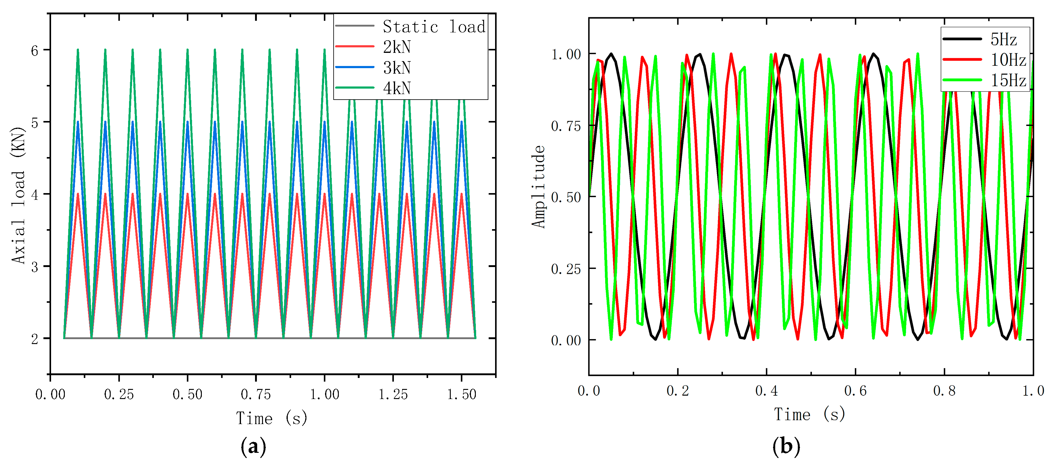
2.2.3. Application of Impact Load

To simplify the simulation of percussive drilling, the total drilling duration was set to 10 s, assuming that the axial impact sub delivers constant and periodic impact energy. Based on the kinetic energy equation and the momentum theorem, the impact energy was integrated and converted into the maximum axial impact force applied in the loading step. Figure 2a shows the amplitude curve of the dynamic load after superposition. While the bit rotates, it is subjected to a periodic axial impact force at a frequency of 10 Hz, and a static load of 2 kN, representative of conventional drilling, is superimposed as well. Figure 2b presents the impact frequency curve. To better control the input frequency, the axial impact frequency was defined as f n . The impact amplitude is governed by a user-defined input amplitude function, while the impact frequency is determined by the initial impact interval and the angular frequency of the periodic input.
The simulation parameters were selected based on actual operating conditions, as summarized in Table 5. A total of 16 simulation cases were designed under different working conditions. For each case, a specific control function was defined according to the corresponding control parameters. This study investigates the influence of key parameters—including the rotation speed (30–210 rpm), impact amplitude (4–12 kN), impact frequency (10–400 Hz), and weight on bit (1–3 t)—on the characteristics of impact-induced vibration.

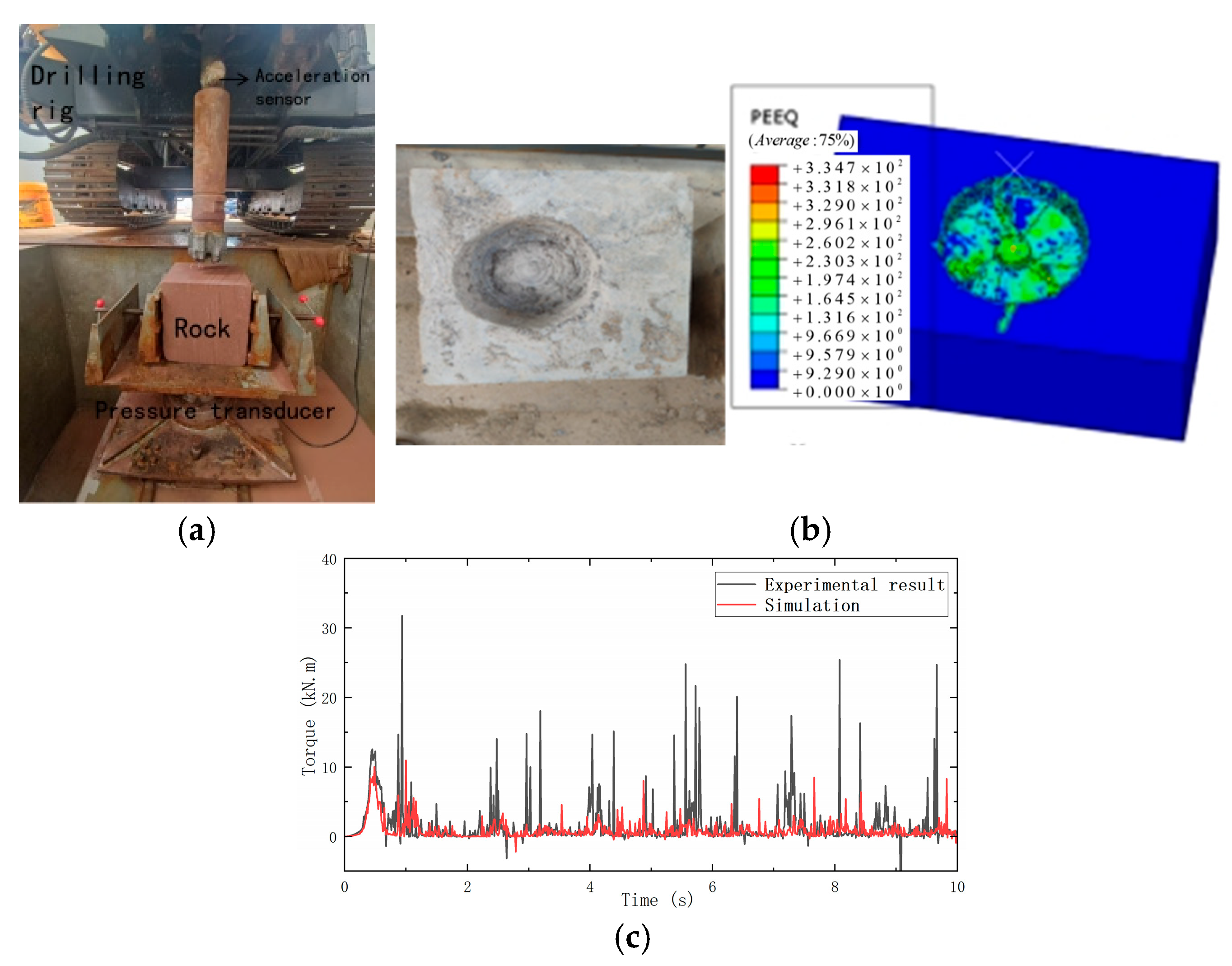
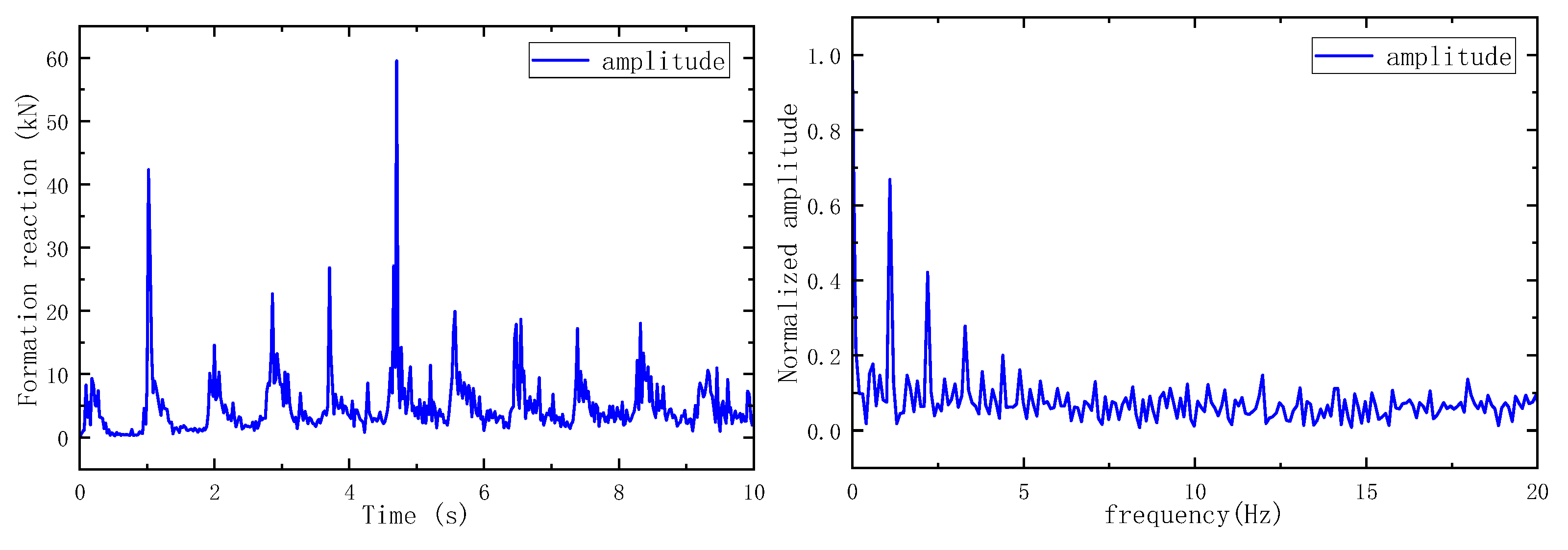
2.3. Model Validation

To verify the accuracy of the material properties and geometric dimensions in the simulation model, laboratory rock-breaking experiments were conducted using a PDC bit. The tests were performed under a weight on bit (WOB) of 2 kN and a rotation speed of 80 r/s. Torque during the rock-breaking process were recorded via sensors. The same loading conditions were applied to the simulation model, and the stress at the cutter positions was extracted for comparison. The experimental setup is shown in Figure 3a, while the simulation results and the rock-breaking outcomes are illustrated in Figure 3b and Figure 3c, respectively. The torque curve shows fluctuations around 10 kN, exhibiting a variation trend similar to the experimentally measured torque. During the loading process, a clear drop in torque followed by prominent peak values can be observed, indicating slight bit bounce and intermittent penetration under sustained axial loading. These observations confirm that the established nonlinear dynamic simulation model of the drill string assembly is reliable and capable of realistically reproducing the actual drilling behavior.

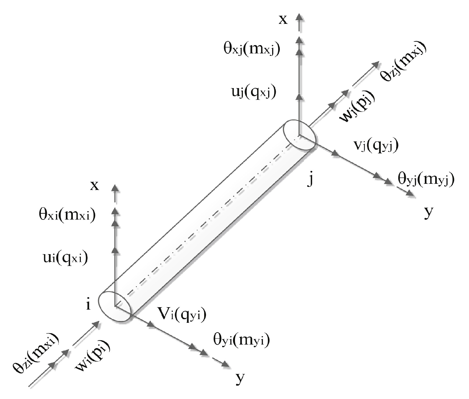
2.4. Drill String Vibration Model

To investigate the vibration-induced damage of the drill string system under impact loading, a simplified drill string model was established, as shown in Figure 4.
In the simplified drill string model, the drill pipe, BHA, and drill bit are connected by linear springs with torsional stiffness and damping. During the drilling process, the WOB drives the bit into the formation while the rotary table rotates the BHA by actuating the kelly, thereby enabling the drill bit to rotate and cut through the rock. The lower BHA and bit are modeled as a simplified flywheel. The drilling response of the bit is primarily characterized by the interaction between the weight on bit (W), torque ( T m ), moment of inertia ( J ), penetration rate (V), and angular velocity ( ω ).
The drill string is divided into multiple components, with each element within a single component having constant geometric and material properties. Each node is assigned three translational degrees of freedom and three rotational degrees of freedom. Set w ,   u ,   v represent the axial displacements of the drill string in three directions, θ x , θ y , θ z , denote the rotational angles (twist) in each direction, and q ,   m indicate the shear forces and bending moments experienced by the drill string. The finite element force model for a single drill string element is illustrated in Figure 5.
In the drill string system, the displacements at each node constitute the generalized coordinates of the system. Based on the assumed displacement field, the translational deformation of the element is expressed using shape functions as follows:
ω ( z , t ) = [ N w ] { u 1 } u ( z , t ) = [ N w ] { u 2 } v ( z , t ) = [ N v ] { u 3 } θ ( z , t ) = [ N θ ] { u 4 }
where:
{ u 1 } = { u i , θ y i , u j , θ y j } T { u 2 } = { v i , θ x i , v j , θ x j } T { u 3 } = { w i , w j } { u 4 } = { θ z i , θ z j }
[ N w ] , [ N u ] , [ N v ] , [ N θ ] denotes the displacement interpolation (shape) function, and u 1 , u 2 , u 3 , u 4 represents the displacement vector. The total energy of the element consists of kinetic energy and potential energy. Using time derivatives, the expression for kinetic energy is given by:
T e = 1 2 { u ˙ 1 } T [ m S A ] { u 1 } 1 2 { u ˙ 2 } T ( [ m S D ] + [ m S R ] ) { u ˙ 2 } + 2 Ω { u ˙ 1 } [ J s ] { u 2 } 1 2 { u ˙ 3 } T ( [ m S D ] + [ m S R ] { u ˙ 3 } ) + 1 2 { u ˙ 4 } T [ m S A ] { u ˙ 4 } + 1 2 J Q 2
where m S A denotes the axial translational mass matrix of the element; m S D is the transverse (lateral) mass matrix; m S R represents the rotational mass matrix; and J s is the inverse mass matrix of the element.
By integrating the drill string vibration model with the wellbore vibration equations, a coupled dynamic model of the wellbore–drill string–bit–rock system is established:
M . U ¨ + C . U ˙ + K . U = F ( t )
M ,   K ,   C are the mass, stiffness, and damping matrices, respectively; U ,   U ˙ ,   U ¨ are the displacement, velocity, and acceleration vectors, respectively; and F ( t ) is the external force vector acting on the system.

2.5. Bit–Rock Interaction Analysis

The cyclic impact force between the rock and the applied loading is a major excitation source for the vibration of the BHA within the wellbore. During the drilling process, the bit is simultaneously subjected to torque from the drill string, axial impact loads from the impactor, as well as resistance and reaction forces from the formation being drilled [19,20,21]. Based on force equilibrium analysis, the expression of the impact force during drilling can be written as:
F = 1.762 × m E 2 / 3 × R 2 / 5 × ( Q H ) 3 / 5
m E is the deformation modulus of the rock, kPa; R is the equivalent volumetric radius of the falling rock, m; Q is the mass of the falling rock, t; and H is the impact height.
According to the axial impact force equation of the drill bit:
P z ( t ) + m z a ( t ) + F z ( t ) = 0 P z ( t ) = W O B F f z ( L )
where m b is the mass of the drill bit, A b is the cross-sectional area of the impact hammer, v 0 is the impact velocity, u ( t ) is the footage depth of the drill bit, ρ is the density of the hammer material, and c is the longitudinal wave velocity of the material, m/s.
The axial force model of the drill bit is given as follows:
P z ( t ) + m z a ( t ) + F z ( t ) = 0 P z ( t ) = W O B F f z ( L , μ , θ )
P z ( t ) is the drilling pressure from the drill string at time t, kN; m z is for the mass of the drill bit, kg; F z ( t ) is the longitudinal reaction force of the rock to the drill bit at time t, kN; WOB refers to the Weight on Bit; and F f z ( L , μ , θ ) represents the borehole wall frictional resistance in the z-direction, while fluid resistance is neglected.

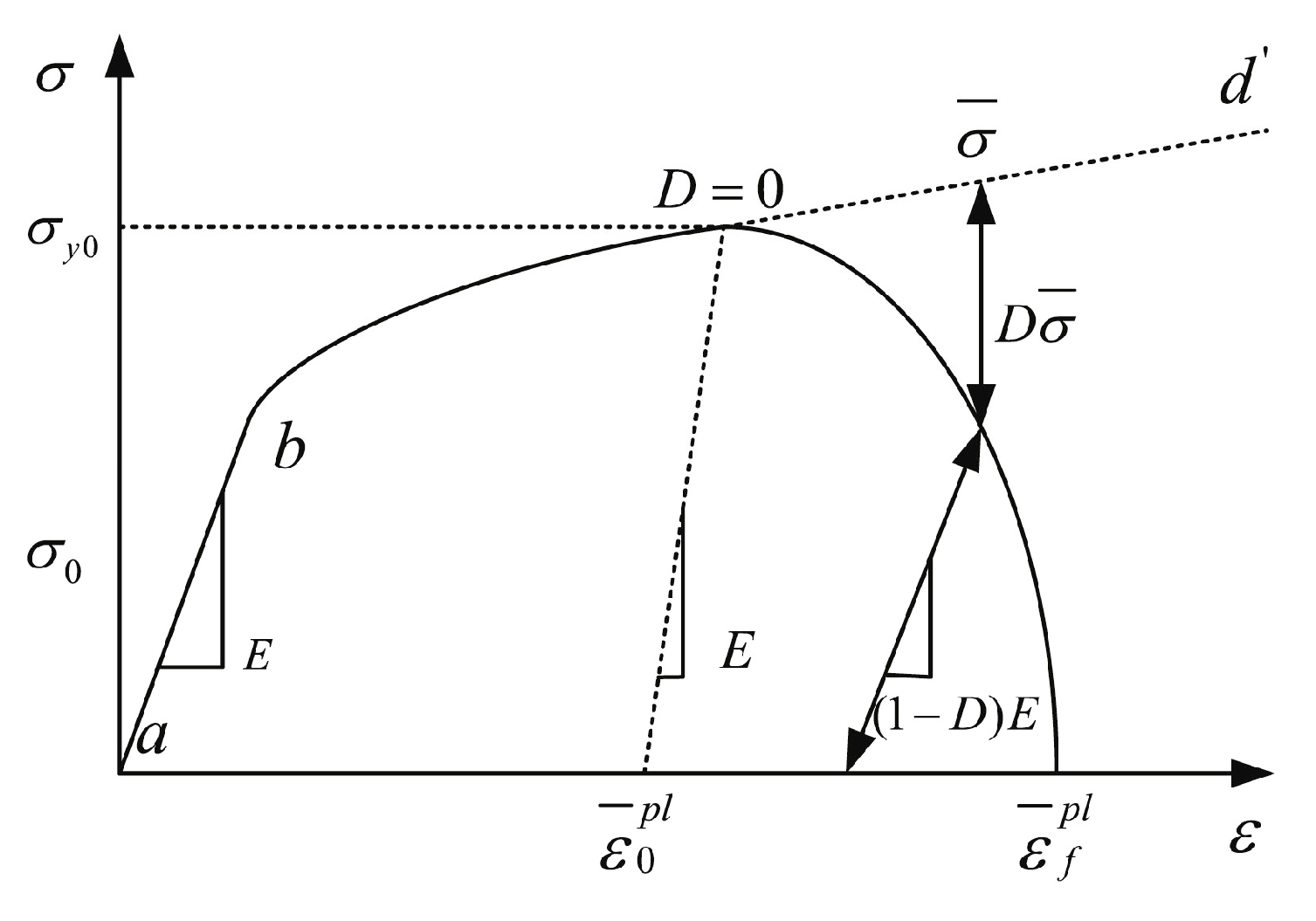
2.6. Rock Constitutive and Failure Criteria

Rock materials exhibit characteristics such as nonlinearity, elastoplasticity, viscoelasticity, dilatancy, and anisotropy. In rock mechanics, the commonly used constitutive models for rock materials include the Mohr–Coulomb and Drucker–Prager (D–P) criteria [22,23]. The D–P criterion is based on the Mohr–Coulomb model but incorporates the influence of hydrostatic pressure, allowing for a better representation of material behavior under complex stress conditions. In the D–P model, the rock is treated as an isotropic damage material, where the degradation of stiffness is characterized by a damage variable D. The value of D ranges from 0 to 1, with D = 1 indicating a complete loss of strength, representing rock failure, spalling, or fragmentation. The stress–strain relationship of the rock is illustrated in Figure 6.
The standard definition of rock damage is given as follows:
ε p ε ¯ f p l
where ε ¯ f p l is the equivalent plastic strain of rock failure and ε p is the equivalent plastic strain.
The rock damage variable is defined as:
D = 1 E E
E and E are the elastic moduli of the damaged and undamaged material, respectively.

2.7. Drill String Fatigue Solving Strategy

According to the axial impact force equation of the drill bit:
m b K d 2 d t 2 u ( t ) + ρ c A b K d d t u ( t ) = p c A b K v 0
where m b is the mass of the drill bit, A b is the cross-sectional area of the impact hammer, v 0 is the impact velocity, u ( t ) is the footage depth of the drill bit, ρ is the density of the hammer material, c is the longitudinal wave velocity of the material, m/s, and K represents the axial stiffness of the drill string system, N/m.
Considering the small deformation of the drill string system [24,25,26,27], the Mizers equivalent stress is used to calculate the synthesis of stress:
σ e q max = 1 2 σ z + σ b max σ r 2 + ( σ r σ t ) 2 + ( σ t σ z σ b max ) 2
σ e q min = 1 2 σ z + σ b max σ r 2 + ( σ r σ t ) 2 + ( σ t σ z + σ b max ) 2
The formula for calculating the fatigue damage under a given stress is as follows:
N = N 1 i = 1 l α i ( σ i σ L ) d
N is the total life; σ i is the stress amplitude at the highest stress level, MPa; N 1 is the fatigue life under stress; α i is the σ i ratio of the number of cycles at a given stress level to the total number of cycles; d represents the material damage index; and l is the index of the stress level.

3. Results and Discussion

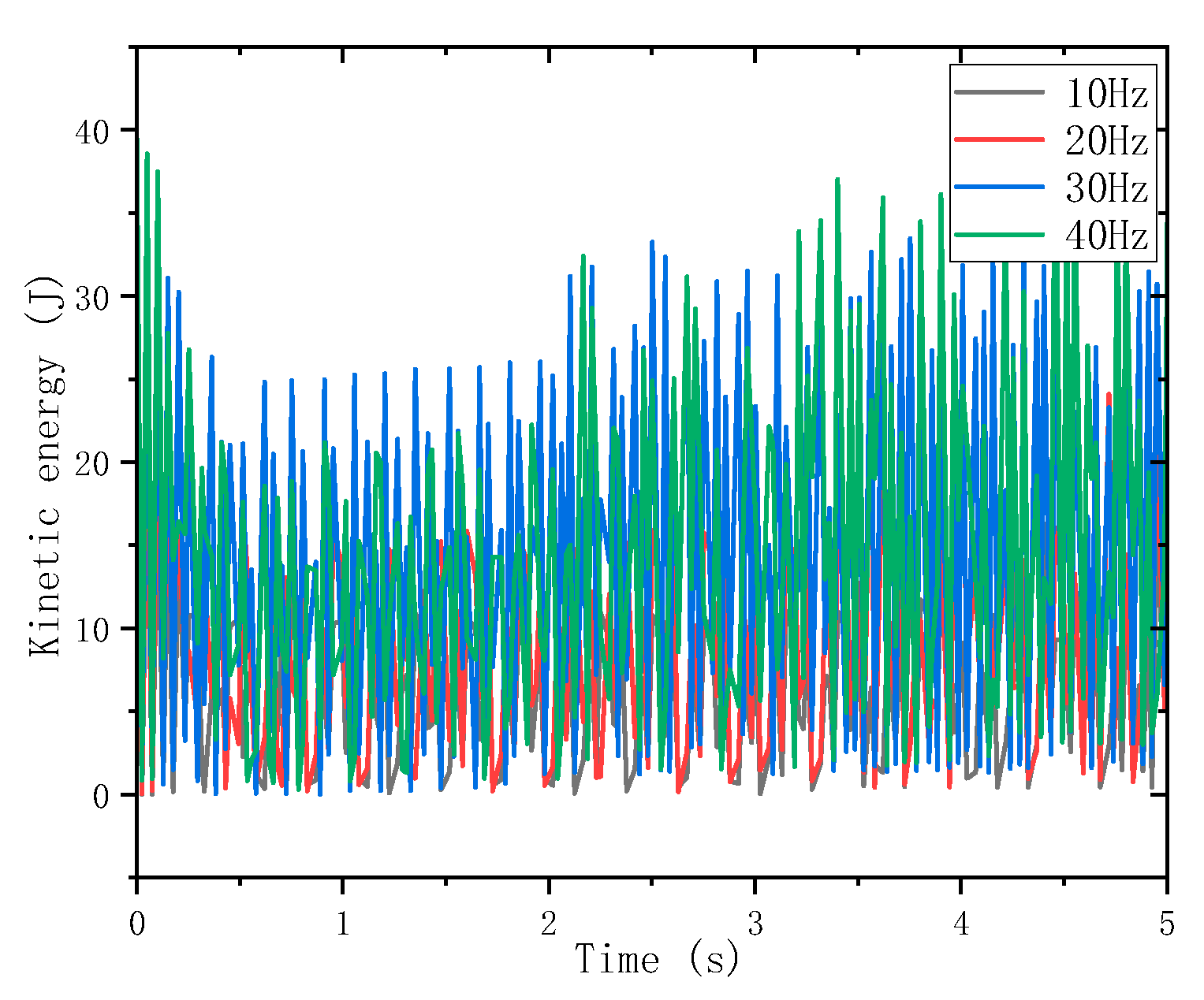
3.1. Effect of Different Impact Energies on BHA Vibration

During percussive drilling, the torque and unidirectional axial impact are simultaneously applied at the bottom of the drill bit. The periodic impact load is fully converted into the initial drilling velocity of the bit acting on the rock. To analyze the vibration-induced damage of the drill string under impact drilling, numerical simulations are performed in which the rock elements, modeled using the D–P criterion, fail when the damage variable exceeds its maximum threshold during drilling. The impact parameters used in field operations are transformed into the bit’s impact velocity based on the kinetic energy equation, and simulations are conducted to evaluate the percussive drilling process under different impact force levels.
As shown in Figure 7, the rock fragmentation process after percussive drilling reveals that the damage of rock path elements varies periodically with the bit impacts. Due to the cyclic axial loading, the formation exhibits regular deep fracturing and damage patterns. When the bit contacts the rock, the cutting teeth penetrate the formation under the combined effect of weight on bit and the axial impact load. Subsequently, under the applied torque, the outermost rock layer begins to fracture, leading to a localized stress concentration. After the thin rock layer is broken, the bit rapidly retracts due to the drop in the impact load and then the bit repeats the rock-breaking process in the next impact cycle.
As shown in Figure 8, the variation curve of the axial impact force on the drill string during a 10 Hz percussive drilling process indicates that when the periodic impact energy applied to the bit gradually increases, the axial stress in the drill string fluctuates intensely. The maximum axial stress reaches approximately 500 MPa. Under an impact force of 6 kN, the amplitude frequency of the drill string increases and the descent rate accelerates, indicating that increasing the impact energy significantly enhances the ROP. However, the axial vibration of the drill string also becomes more pronounced. This suggests that when the impact energy is excessively high and mismatched with the drilling parameters, the impact load acting on the bit decreases, while drill string vibrations intensify, leading to sudden peak stresses. Such conditions may adversely affect both the drilling efficiency and the service life of the drill string.
Figure 9 shows the torque variation curve of the drill string under percussive drilling. During the 10 s simulation, the torque fluctuates within ±30 kN·m. Considering the enhanced ROP provided by the impactor, the drill string is subject to significant vibration disturbances. As the impact force increases, the torque on bit (TOB) also rises, indicating that a greater impact force leads to faster bit penetration. Consequently, the contact time and area between the bit and the formation increase, which raises the required torque and the energy consumed to overcome friction. This results in more severe torque fluctuations in the drill string, indicating that vibration and damage under percussive drilling are greater than those in conventional rotary drilling. Moreover, when the input impact force of the hydraulic impactor increases, both the amplitude and frequency of the drill string torque variations are intensified.
Figure 10 presents the energy consumption curves for conventional drilling and percussive drilling. It can be observed that increasing the impact force leads to greater energy consumption in the drill string system, with more pronounced fluctuations, further complicating the stress variations within the bottom hole assembly.

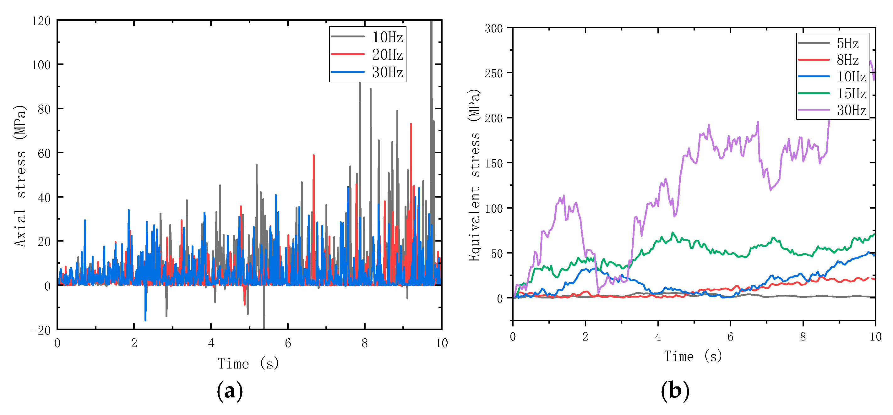
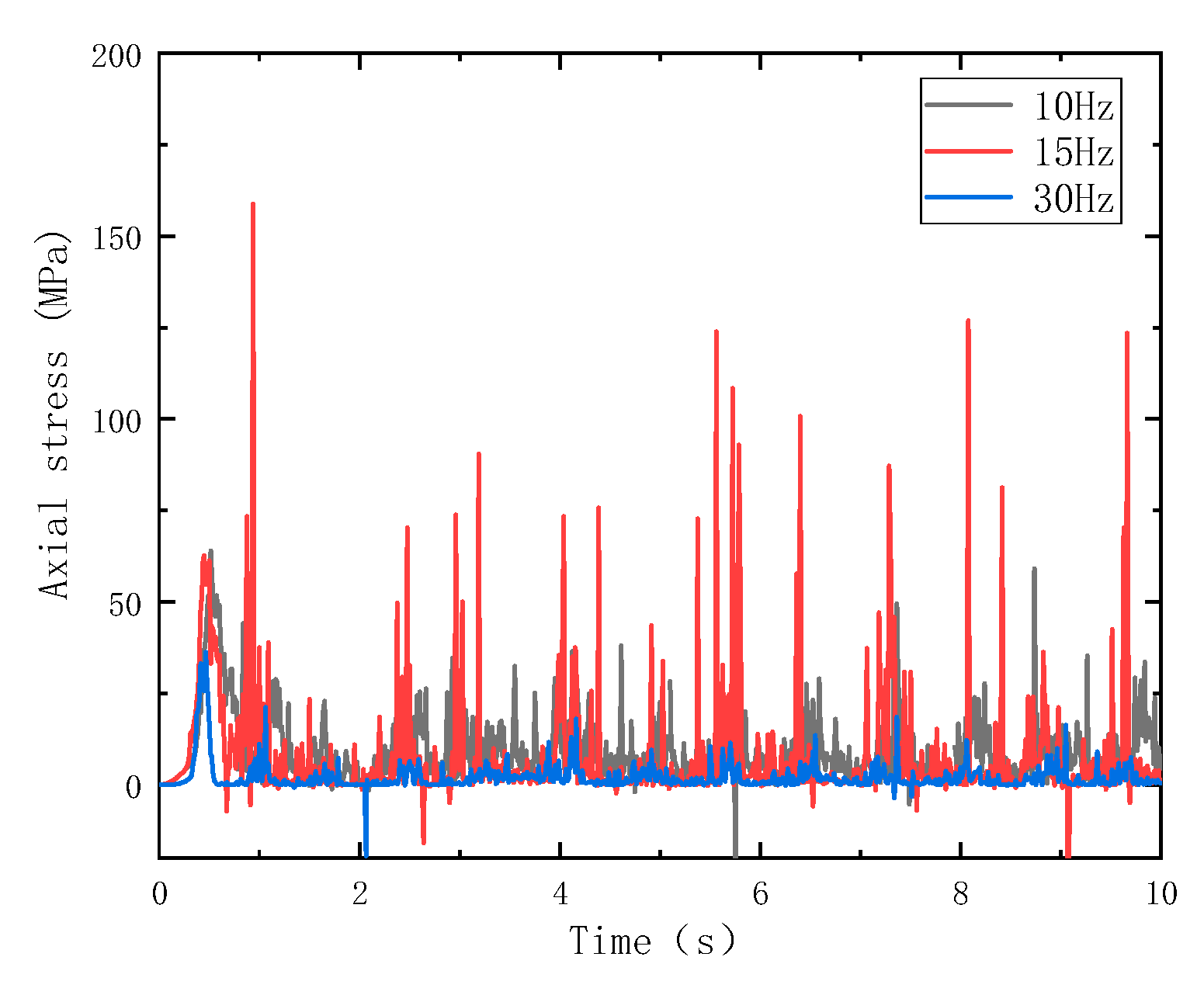
3.2. Effect of Different Impact Frequencies

Under actual operating conditions, the hydraulic impactor uses drilling fluid as the power medium. It converts high-pressure fluid energy and dynamic water hammer energy into continuous impact loads, functioning as a bottom hole dynamic tool. According to the impact frequency control equation, the impact frequency f increases with the flow rate. To simplify the simulation process, each impact is assumed to apply the same magnitude of force, while only the angular frequency (corresponding to the impact period) in the input load control table is varied. The rotary speed is uniformly set to 60 r/mi. As shown in Figure 11, the axial force response of the drill string under different impact frequencies is analyzed. Within the 10–30 Hz range, the axial force of the drill string exhibits a periodic vibration pattern characterized by alternating stress peaks and troughs over time. During each peak, the axial load increases as the bit is pressed into the formation; subsequently, the cutting teeth fracture and penetrate the rock, resulting in a smaller peak in axial force. The duration of each peak corresponds to the phase in which the rock debris is gradually detached. Therefore, a higher frequency of axial stress peaks corresponds to a faster rate of penetration. This also indicates that the axial impactor increases the frequency of alternating stresses acting on the drill string, potentially accelerating fatigue damage and shortening the service life.
Figure 12 shows the torque variation curves of the drill string under different impact frequencies. It can be observed that at 20 Hz, the drill string experiences larger torque fluctuation amplitudes, whereas at higher frequencies, the fluctuations are comparatively smaller. Higher peaks in axial torque result in intensified torsional vibrations in the drill string. The maximum observed torque reaches 164.2 kN·m, which increases the risk of drill string collisions with the wellbore wall. Moreover, excessive torque can negatively affect the fatigue life of the drill string. This indicates that if the input impact frequency does not match the actual drilling conditions, it may aggravate fatigue damage and stress variation in the BHA.
As shown in Figure 13, under the same impact force, the vibration amplitude at the borehole bottom is relatively small at lower impact frequencies. As the impact frequency increases, the amplitude variation increases proportionally. In the high-frequency range, the vibration becomes more intense, with sharper changes in the amplitude curve. This demonstrates that higher-frequency impacts result in more severe vibrations and greater energy dissipation.

3.3. Fatigue Life Analysis of Drill Strings

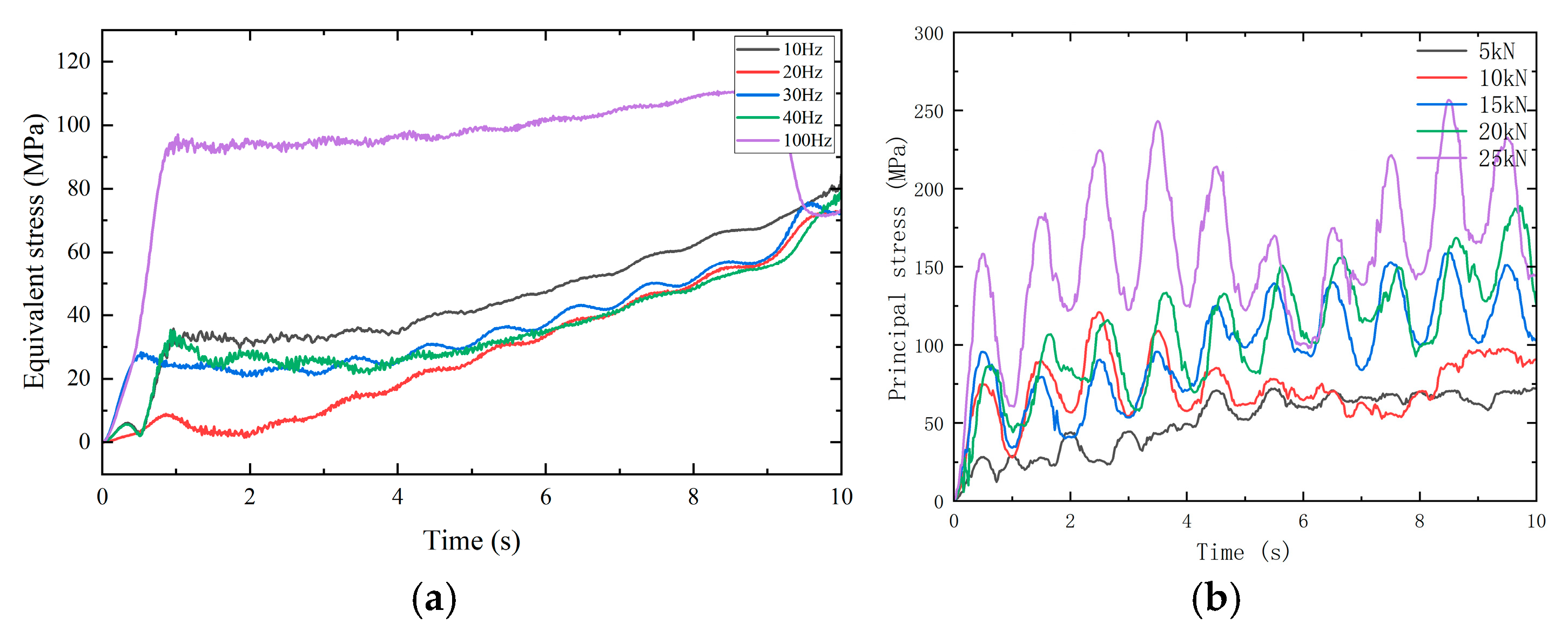
3.3.1. Equivalent Stress Analysis of Drill Strings

During percussive drilling, the BHA is subjected not only to impact stresses caused by drill string–wellbore collisions, but also to axial vibrations and reverse torsional stresses generated during rock-breaking. These factors significantly increase the complexity of the mechanical loads acting on the BHA. To visualize the buckling behavior of the BHA during percussive drilling, the displacement of the drill string assembly and the formation reaction force under different impact energy levels are extracted, as shown in Figure 14.
As shown in Figure 15, under low impact forces, the bending of the drill string is not pronounced, with buckling primarily concentrated near the top of the drill rod. As the impact force increases, the curvature of the drill rod becomes more severe, causing a slight inclination at the bit. The main bending region remains concentrated along the drill rod, while the location of the maximum equivalent stress appears near the bottom hole assembly. This indicates that as the impact force increases, the more flexible parts of the drill string, such as the rods, tend to buckle first, initiating vibration in the BHA. Moreover, during the impact drilling of hard rock formations, the bit may experience bit bounce (jumping), but the vibration is gradually suppressed under stable drilling conditions. The extracted stress data will be used in the next chapter for the fatigue analysis of the drill string.
The equivalent stress at the stress concentration points of the drill string assembly under different impact loads is extracted, as shown in Figure 16a. It can be observed that the equivalent stress in the drill string exhibits periodic variation, indicating that before each rock layer is fractured during percussive drilling, the equivalent stress gradually accumulates. As penetration progresses, this process is repeated. With the increasing impact load, the fluctuation trend becomes more pronounced. At an impact frequency of 100 Hz, the maximum stress experienced by the drill string significantly increases, with the peak equivalent stress reaching 109.5 MPa, representing a 55.3% increase compared to the condition at 40 Hz. This suggests that higher-frequency impacts result in an increased energy transfer to the drill string and intensified vibration.
The post-processed axial stress variation curves under different impact loads are shown in Figure 16b. Compared with the influence of an increasing impact frequency, lower impact forces produce higher axial stress peaks in the drill string, suggesting that the impact load has a more direct effect than the frequency on stress levels. As the impact force increases, the trend of stress variation becomes more uniform, but the magnitude remains large. Under a 25 kN impact load, the maximum axial stress reaches 243.7 MPa, indicating a significant influence of the impact force on the fatigue life of the drill tool. At an impact load of 15 kN, regular fluctuations in stress peaks begin to emerge, implying that the drill bit gains sufficient kinetic energy at this level to penetrate the formation more effectively. In high-impact load operating ranges, the drill string’s fatigue life is expected to decrease due to intensified cyclic stress amplitudes.

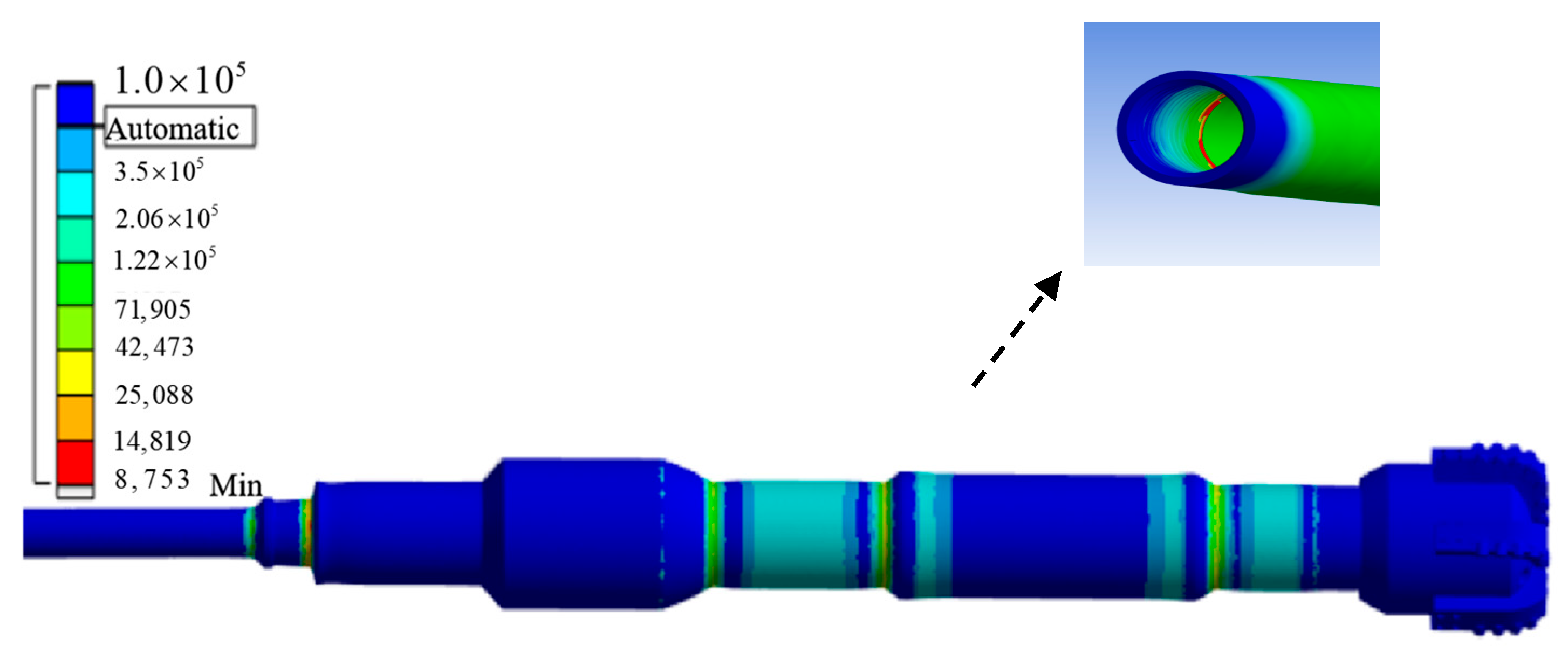
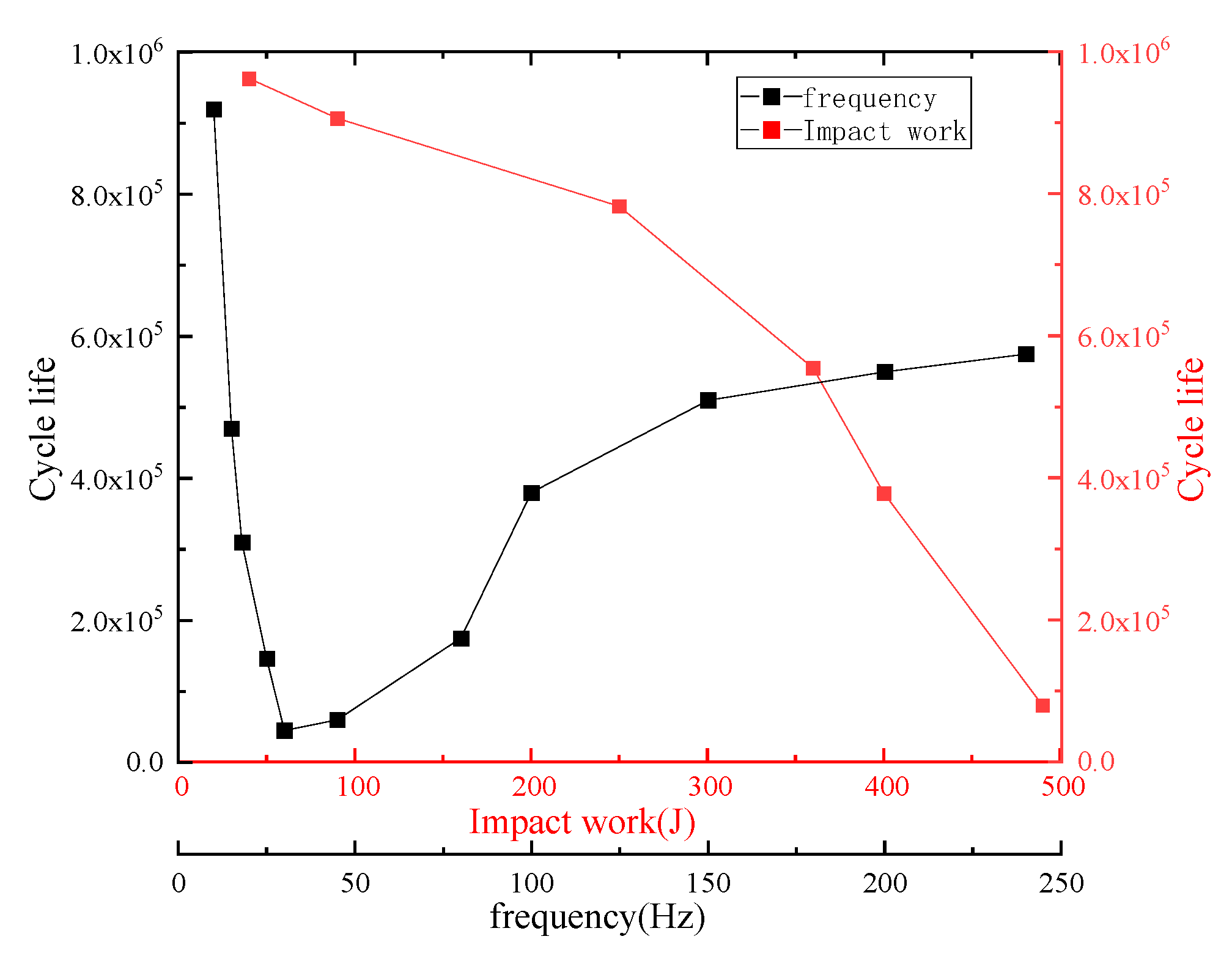
3.3.2. BHA Fatigue Life Analysis

Based on the fatigue analysis module, a study was conducted on the fatigue damage of the BHA under impact-induced vibration. The equivalent stress amplitude and loading frequency obtained from previous simulations were used as input conditions for the fatigue analysis. A coupled finite element model of the system was established. Using the Static Structural module in the ANSYS Workbench, the stress, deformation, and other responses of the system under impact loading were computed, enabling a vibration fatigue life prediction of the drill string assembly. Combining the results from the dynamic response analysis, the critical stress points on the BHA were extracted. Based on the material S-N curve, a vibration fatigue life analysis of the drill string assembly was carried out. The impact load was applied at the reference sub-location in the form of a sinusoidal amplitude–time curve, defined as Step 1. The equivalent stress at the critical point was then applied as a cyclic load on the outer surface of the drill string, with the far-end cross-section set with elastic boundary conditions to simulate drill string connections. The formation reaction force was applied at the bottom surface of the bit, defined as Step 2. The resulting fatigue life distribution of the critical section is shown in Figure 17.
The cyclic fatigue life curve of the drill string assembly under different impact forces is plotted in Figure 18. By comparing the minimum fatigue life of various components in the system, it is observed that the lower section of the drill string reaches the fatigue limit first and is most prone to fatigue failure under cyclic percussive vibrations. The minimum fatigue life of the drill string is approximately 6.472 × 10 4 cycles and there is nearly a fivefold difference in life between the lower drill pipe and the drill collar. Fatigue damage is mainly concentrated in the upper threads and the connection between the drill pipe and the bit. Therefore, special attention must be given to monitoring and reinforcing the structural integrity of these connection zones to prevent premature failure.
Figure 19 illustrates the available cyclic fatigue life contour map of the BHA under typical impact forces and impact frequencies of axial impactors, reflecting actual field operating conditions. Based on the relationship among the impact energy, impact frequency, and drill string fatigue life, two envelope regions can be identified at both low and high frequencies. The fatigue life of the drill string generally decreases with the increasing impact frequency. After 30 Hz, the slope of the curve begins to level off, and beyond 60 Hz, the fatigue life curve gradually stabilizes. Interestingly, at high frequencies (above 100 Hz), the fatigue life increases again, indicating that at very high frequencies, the impact load has a relatively smaller effect on fatigue damage. Therefore, if the fatigue life is a primary consideration, it is recommended to operate within the 60–100 Hz impact frequency range. If high-stress amplitudes are needed, higher frequencies such as 100 Hz at the same impact force can generate larger peak stress values. At lower impact energies, the maximum available fatigue life of the drill tool is achieved, although the associated stress amplitude is relatively low. If deep formations are to be penetrated, impact energies above 200 J can be used to generate higher stress amplitudes. However, when the impact energy increases to 400 J, a noticeable inflection point appears in the fatigue life curve, indicating a sharp increase in damage. This suggests that high-energy impact drilling at this level is not suitable for long-term operation.

4. Conclusions

To address the vibration damage prone to occur when using axial impactors in the BHA, a finite element model was established to simulate the interaction between the BHA and the borehole wall. The D-P model was employed to describe rock damage and deformation. By taking the control parameters of the axial impactor as the main variables, the dynamic behavior of the drilling process was studied. The main conclusions are as follows:
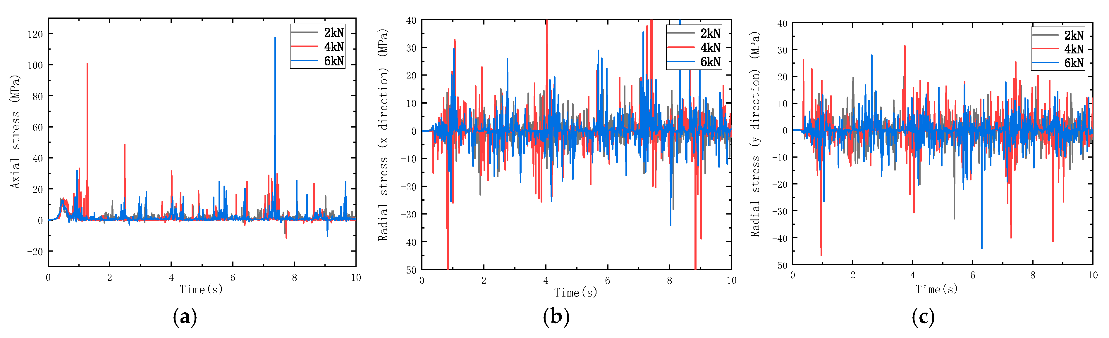
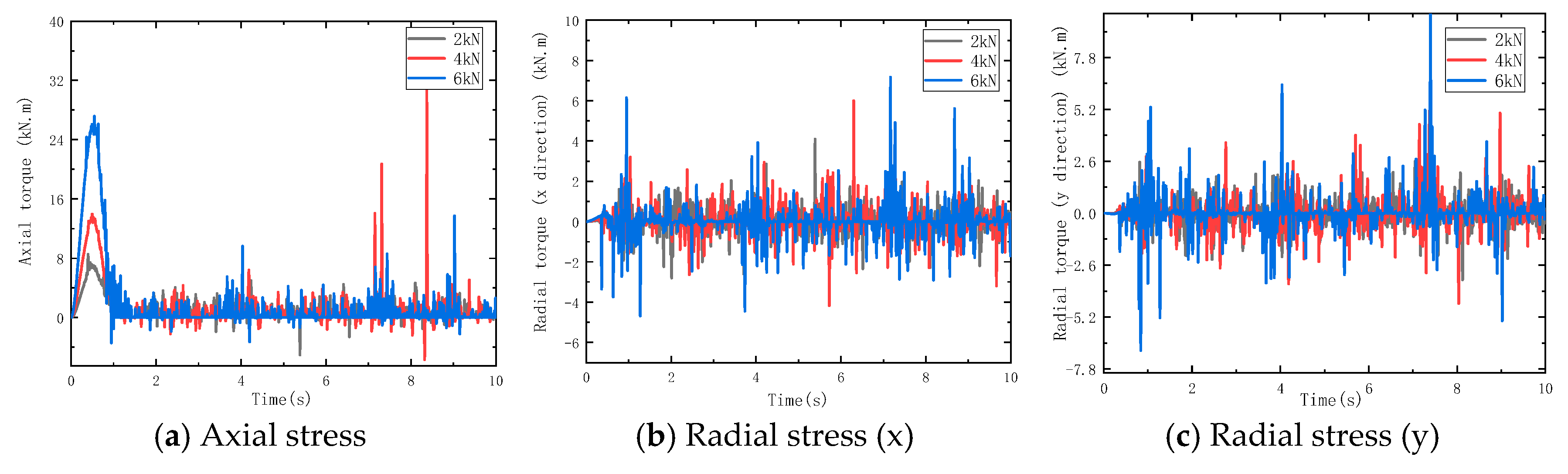
  • Under percussive drilling conditions, axial stress in the drill string fluctuates significantly during rock breaking and penetration. When the input impact force of the hydraulic impactor is increased, both the amplitude and frequency of drill string stress variations become more severe. With the increasing impact frequency, the influence of the impact load on drill string vibration first increases and then decreases, indicating that at high frequencies, the amplitude of alternating stress tends to stabilize and the vibration-induced damage to the drill string is reduced.
  • The effects of impact energy and frequency on BHA behaviors—such as bit bounce, buckling, and fatigue—were analyzed. The results indicate that during impact drilling, slender sections like drill pipe connectors are prone to buckling. The usable fatigue life of these components can be up to four times shorter than that of the bit. Combined with fatigue life curve trends, it is demonstrated that under field conditions, a high-frequency range above 100 Hz coupled with appropriate impact energy effectively mitigates BHA vibration and extends the service life of the drill string system.
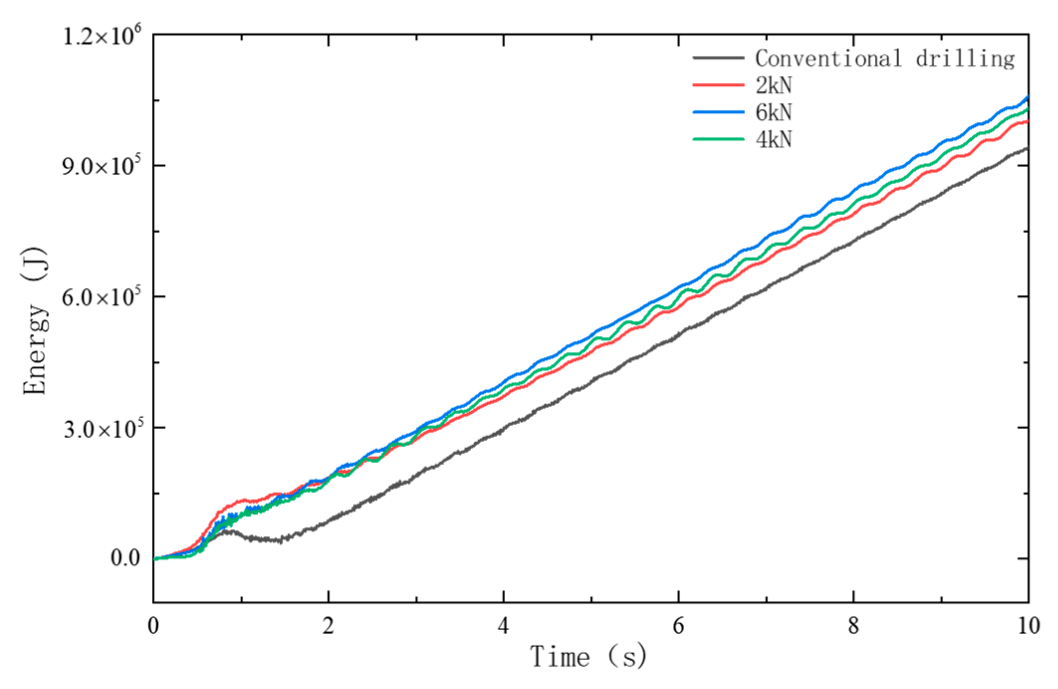
  • Compared with conventional rotary drilling, the drill string motion in the borehole is more complex under percussive drilling. The rate of rock element damage and failure is higher, and both WOB and dynamic stress in the drill string are significantly greater. The findings from this simulation model help provide insight into the complex downhole behavior of the drill string during percussive drilling. This modeling approach offers a novel method for analyzing drill string fatigue life and holds practical significance for drilling optimization and system design.

Author Contributions

Conceptualization, Q.X. and Y.L.; methodology, Q.X.; software, Q.X.; validation, Q.X., Y.L. and J.J.; formal analysis, Y.L.; investigation, J.J.; resources, J.J.; data curation, Q.X.; writing—original draft preparation, Q.X.; writing—review and editing, Q.X.; visualization, L.Z.; supervision, Y.L.; project administration, L.Z.; funding acquisition, L.Z. All authors have read and agreed to the published version of the manuscript.

Funding

This research was funded by Deep Earth probe and Mineral Resources Exploration-National Science and Technology Major Project grant number 2024ZD1000904.

Institutional Review Board Statement

Not applicable.

Informed Consent Statement

Not applicable.

Data Availability Statement

The original contributions presented in this study are included in the article. Further inquiries can be directed to the corresponding author.

Conflicts of Interest

Author Jianbo Jia was employed by the company CNOOC Research Institute Ltd. The remaining authors declare that the research was conducted in the absence of any commercial or financial relationships that could be construed as a potential conflict of interest.

References

  1. Jestin-Fleury, N. International energy agency. World energy outlook. Polit. Étrangère 1994, 59, 564–565. [Google Scholar]
  2. Ghasemloonia, A. Elastodynamic and Finite Element Analysis of Coupled Lateral-Axial Vibration of a Drillstring with a Downhole Vibration Generator and Shock Sub. Ph.D. Thesis, Memorial University of Newfoundland, St. John’s, NL, Canada, 2013. [Google Scholar]
  3. Smith, F.W.; Kopczynski, W. Oilfield percussion drilling. In Proceedings of the SPE Western Regional Meeting, Bakersfield, CA, USA, 2–3 November 1961; SPE: Richardson, TX, USA, 1961. [Google Scholar]
  4. Huang, J.; Zeng, B.; He, Y.; Wang, X.; Qian, L.; Xia, C.; Yi, X. Numerical study of rock-breaking mechanism in hard rock with full PDC bit model in compound impact drilling. Energy Rep. 2023, 9, 3896–3909. [Google Scholar] [CrossRef]
  5. Ju, P.; Tian, D. Improving breaking efficiency of hard rock: Research on the mechanism of impact-shear rock breaking technology. Energy Explor. Exploit. 2025, 43, 451–470. [Google Scholar] [CrossRef]
  6. Baryshnikov, A.; Calderoni, A.; Ligrone, A.; Ferrara, P. A new approach to the analysis of drillstring fatigue behavior. SPE Drill. Complet. 1997, 12, 77–84. [Google Scholar] [CrossRef]
  7. Dong, G.; Chen, P. A review of the evaluation, control, and application technologies for drill string vibrations and shocks in oil and gas well. Shock Vib. 2016, 2016, 7418635. [Google Scholar] [CrossRef]
  8. Guan, Z.-C.; Shao, D.-D.; Wen, X.; Shi, Y.-C. Experimental study on motion characteristics of rotary drill string in horizontal well. Mech. Eng. 2013, 30, 340–345. [Google Scholar]
  9. Dao, N.H.; Sellami, H. Stress intensity factors and fatigue growth of a surface crack in a drill pipe during rotary drilling operation. Eng. Fract. Mech. 2012, 96, 626–640. [Google Scholar] [CrossRef]
  10. Cui, F.; Cao, Y.; Ni, H.; Zhang, H. Impact frequency optimization of automatic vertical drilling and multi-dimensional vibration reduction combined acceleration system based on impact vibration fatigue analysis. China Sci. 2023, 18, 443. [Google Scholar]
  11. Zhi, Z.; Zhu, X. Multiaxial fatigue life of drill pipe joint. Acta Pet. Sin. 2019, 40, 839. [Google Scholar]
  12. Li, W.; Guan, Z.; Zhao, H. Fatigue life prediction of drill string based on reliability theory. Oil Drill. Prod. Technol. 2008, 30, 12–14. [Google Scholar]
  13. Lemma, T.A.; Nanji, P.; Gebremariam, M.A.; Ahsan, S. Remaining useful life prediction of drill string using fuzzy systems and cumulative damage theory. Key Eng. Mater. 2019, 796, 145–154. [Google Scholar] [CrossRef]
  14. Qiu, Z. Analysis of the influence of dynamic factors on BHA of rotary steerable system. West. Prospect. Proj. 2023, 35, 29–33. [Google Scholar]
  15. Li, S.; Yan, T.; Li, W.; Bi, F. Mechanism and test analysis of PDC bit torsional impact rock breaking. J. Yangtze Univ. 2015, 12, 48–51. [Google Scholar]
  16. Song, C.; Chung, J.; Cho, J.-S.; Nam, Y.-J. Optimal design parameters of a percussive drilling system for efficiency improvement. Adv. Mater. Sci. Eng. 2018, 2018, 2346598. [Google Scholar] [CrossRef]
  17. Depouhon, A.; Denoël, V.; Detournay, E. Numerical simulation of percussive drilling. Int. J. Numer. Anal. Methods Geomech. 2015, 39, 889–912. [Google Scholar] [CrossRef]
  18. Yang, Y.; Liao, H.; Niu, J.; Wang, Z.; Chen, J. Three-dimensional simulation of rock breaking efficiency under various impact drilling loads. Arab. J. Geosci. 2020, 13, 444. [Google Scholar] [CrossRef]
  19. Liu, J.; Hei, C.; Luo, M.; Yang, D.; Sun, C.; Feng, A. A study on impact force detection method based on piezoelectric sensing. Sensors 2022, 22, 5167. [Google Scholar] [CrossRef]
  20. Pavlovskaia, E.; Hendry, D.C.; Wiercigroch, M. Modelling of high frequency vibro-impact drilling. Int. J. Mech. Sci. 2015, 91, 110–119. [Google Scholar] [CrossRef]
  21. Zhu, X.; Tang, L.; Tong, H. Effects of high-frequency torsional impacts on rock drilling. Rock Mech. Rock Eng. 2014, 47, 1345–1354. [Google Scholar] [CrossRef]
  22. Aydan, O.; Tokashiki, N.; Genis, M. Some considerations on yield (failure) criteria in rock mechanics. In Proceedings of the ARMA US Rock Mechanics/Geomechanics Symposium, Chicago, IL, USA, 24–27 June 2012; p. ARMA–2012-2640. [Google Scholar]
  23. Yan, B.; Wang, P.; Ren, F.; Guo, Q.; Cai, M. A review of mechanical properties and constitutive theory of rock mass anisotropy. Arab. J. Geosci. 2020, 13, 487. [Google Scholar] [CrossRef]
  24. Vaisberg, O.; Vincke, O.; Perrin, G.; Sarda, J.; Fay, J. Fatigue of drillstring: State of the art. Oil Gas Sci. Technol. 2002, 57, 7–37. [Google Scholar] [CrossRef]
  25. Zheng, J. Fatigue Estimation of Drill-String and Drill-Pipe Threaded Connection Subjected to Random Loadings. Master’s Thesis, Memorial University of Newfoundland, St. John’s, NL, Canada, 2015. [Google Scholar]
  26. Ritto, T.; Soize, C.; Sampaio, R. Robust optimization of the rate of penetration of a drill-string using a stochastic nonlinear dynamical model. Comput. Mech. 2010, 45, 415–427. [Google Scholar] [CrossRef]
  27. Wada, R.; Kaneko, T.; Ozaki, M.; Inoue, T.; Senga, H. Longitudinal natural vibration of ultra-long drill string during offshore drilling. Ocean Eng. 2018, 156, 1–13. [Google Scholar] [CrossRef]
Figure 1. Meshing and boundary conditions of the drill string system–wellbore–rock formation model. (a) Wall-BHA-rock model; (b) meshing.
Applsci 15 07388 g001
Figure 2. Impact load amplitude curve: (a) axial load and (b) impact frequency.
Applsci 15 07388 g002
Figure 3. Comparison of torque between experimental and numerical results: (a) tracked percussive drilling rig platform; (b) test results; and (c) torque curve.
Applsci 15 07388 g003
Figure 4. BHA simplified model.
Applsci 15 07388 g004
Figure 5. Stresses and deformations of beam elements.
Applsci 15 07388 g005
Figure 6. Stress–strain relationship of rock.
Applsci 15 07388 g006
Figure 7. Rock breakage at the borehole base over time: (a) t = 0.764 s; (b) t = 1.153 s; (c) t = 3.234 s; and (d) t = 5.154 s.
Applsci 15 07388 g007
Figure 8. Stress curve in all directions of the drill string: (a) axial stress; (b) radial stress (x); (c) radial stress (y).
Applsci 15 07388 g008
Figure 9. Drill string torque curve with time: (a) axial stress; (b) radial stress (x); (c) radial stress (y).
Applsci 15 07388 g009
Figure 10. Total energy curve under percussion drilling.
Applsci 15 07388 g010
Figure 11. Stress curves of drill strings under different impact frequencies: (a) axial stress; (b) equivalent stress.
Applsci 15 07388 g011
Figure 12. Torque curve of extracted drill string under different impact frequencies.
Applsci 15 07388 g012
Figure 13. Variation curve of bottom hole kinetic energy under different impact frequencies.
Applsci 15 07388 g013
Figure 14. Combined displacement of the bottom drilling tool under different impact forces (2 times magnification factor): (a) conventional drilling; (b) 2 kN; (c) 6 kN; (d) 8 kN.
Applsci 15 07388 g014
Figure 15. Analysis curves of formation reaction force and amplitude during drilling.
Applsci 15 07388 g015
Figure 16. Variation of equivalent stress in drill string under different control parameters: (a) impact frequency; (b) impact force.
Applsci 15 07388 g016
Figure 17. Contour of fatigue life of drilling tool combination.
Applsci 15 07388 g017
Figure 18. The usable life of different parts of the drilling tool combination under different impact forces.
Applsci 15 07388 g018
Figure 19. Line chart of available cyclic fatigue life of the drill string assembly under different control parameters.
Applsci 15 07388 g019
Table 1. Drilling tool combination material parameters.
ComponentElastic Modulus
(GPa)
Density
(kg/m3)
Poisson’s RatioTensile Strength
(MPa)
Impactors20778500.301.08 × 103
Drill Collar20778500.301.05 × 103
Stabilizer22078500.301.03 × 103
Drill Bit57915,0000.223.54 × 103
Table 2. Simulated material parameters.
ComponentDensity
(kg/m3)
Young’s Modulus
(GPa)
Poisson’s RatioShear Strength
(MPa)
Tensile Strength
(MPa)
Drill String78642150.321001200
Drill Bit7864Rigid Body
Borehole Wall2439Rigid Body
Table 3. Rock mechanics parameters.
Ya an Granite
Density (kg/m3)2750
Young’s Modulus (GPa)36.5
Poisson’s Ratio0.25
Tensile Strength (MPa)8.91
Uniaxial Compressive Strength (MPa)150
Friction Angle (°)33.52
Porosity (%)1.241
Table 4. Contact property settings.
NumberMain SurfaceSlave SurfaceContact Property
CP-1Bit bottom surfaceRock mass partIntOrop-1
CP-2Drill bit topBHA assemblyBind
CP-3Drill string systemWellbore wallIntOrop-1
CP-4Rock surfaceRock mass partSelf-contact
Table 5. Simulation parameters.
Rock-Confining Pressure (MPa)Rotary Speed
(rpm)
Impact Amplitude
(kN)
Impact Frequency (Hz)Weight on Bit (t)Simulation Duration (s)
2030~2104~1210~4001~310
Disclaimer/Publisher’s Note: The statements, opinions and data contained in all publications are solely those of the individual author(s) and contributor(s) and not of MDPI and/or the editor(s). MDPI and/or the editor(s) disclaim responsibility for any injury to people or property resulting from any ideas, methods, instructions or products referred to in the content.

