Abstract
This study addresses the urgent demand for high-precision manufacturing of curved components by developing a fully servo-driven multi-axis controlled four-roll bending machine. By integrating a modular symmetric roller system design with a distributed hierarchical motion control architecture, we achieved substantial enhancements in scalability, forming stability, and machining accuracy. The mechanical system underwent static simulation optimization using SolidWorks Simulation, ensuring maximum stress in the guiding mechanism was controlled below N/m². ABAQUS-based roll-bending dynamic simulations validated the geometric adaptability and process feasibility of the proposed mechanical configuration. A master-slave dual-core control architecture was implemented in the control system, enabling synchronized error ≤ 0.05 mm, dynamic response time ≤ 10 ms, and positioning accuracy of ±0.01 mm through collaborative control of the master controller and servo drives. Experimental validation demonstrated that the machine achieves bending errors within 1%, with an average forming error of 0.798% across various radii profiles. The arc integrity significantly outperforms conventional equipment, while residual straight edge length was reduced by 86.67%. By adopting fully servo-electric cylinder actuation and integrating a C#-developed human–machine interface with real-time feedback control, this research effectively enhances roll-bending precision, minimizes residual straight edges, and exhibits broad industrial applicability.
1. Introduction
The four-roll bending machine, as a core piece of equipment in the field of metal plastic forming, plays an irreplaceable role in aerospace, rail transit, new energy equipment manufacturing, and other sectors due to its high forming efficiency and capability to process complex curved surfaces [1]. However, with the growing demand for high-precision, multi-specification bent components in modern industry, the limitations of traditional rolling machines in terms of mechanical architecture and control systems have gradually become apparent: the rigid coupling design of mechanical structures leads to insufficient scalability and adaptability, while single-level motion control modes struggle to meet the requirements for multi-axis coordination and high dynamic response during machining. This is particularly pronounced when dealing with highly malleable aluminum profiles [2], where the coupling effects of material springback and dynamic load disturbances often induce forming precision degradation and surface quality defects (such as localized indentations, periodic ripples, and micro-cracks), severely constraining product quality and production efficiency [3,4]. Therefore, addressing the urgent need for precision innovation in high-end equipment manufacturing, conducting in-depth research on key technologies for four-roll bending machines holds significant scientific value and engineering importance.
Recent years have witnessed the irreplaceable engineering significance of CNC bending machines in precision processing of complex bent components [5,6]. For instance, Garad S et al. developed a semi-automatic bending machine addressing manual operation inefficiencies through automation strategies that reduced production cycles by over 40%, lowered costs by 25%, and simultaneously improved product quality and output volume [7]. Amiolemhen P E et al. designed a cost-effective motorized three-roll plate bending machine capable of efficiently bending 6 mm thick mild steel plates at a manufacturing cost of $1363.64 using a 10HP electric motor and specialized component assembly processes [8]. Jing Y et al. validated the feasibility of servo-electric cylinder implementation in four-roll profile bending machines, proposing an adaptive control model based on curve fitting between actual forming curvature (R) and servo cylinder feed (d) values to enable precision processing of various profile specifications with progressively enhanced forming accuracy through iterative testing [9]. von Atzigen, M. et al. developed the world’s first fully automated metal rod bending system by integrating augmented reality (AR) and robotic technology, enabling precise digital shaping of implant rods in spinal fusion surgery. This innovation significantly reduced residual stress at the bone–screw interface (p = 0.0015), shortened operational time, and decreased the number of reduction device engagements (p = 0.0037) compared to the manual gold standard, providing an innovative solution to overcome technical limitations of traditional handheld shaping methods [10].Goto H et al. introduced a novel multi-functional bending machine combining 6-DOF parallel kinematic mechanisms (PKM) with hydraulic servo drives for flexible control of bending radii and angles through dynamic modulation of die motion trajectories and tube feed lengths without requiring tooling changes, significantly improving process adaptability for designer furniture and universal product manufacturing [11]. In the research paradigm combining theoretical breakthroughs with enhanced rolling precision and mechanical performance, GAAIA M et al. proposed an upgrade scheme for the upper roll drive system of plate bending machines integrating dynamic load adaptation, intelligent friction compensation, and multi-objective genetic algorithm optimization, significantly improving sheet metal forming accuracy and equipment service life [12]. Chen P established an experimental-simulation collaborative research framework to systematically reveal the nonlinear correlations between springback rate and rolling speed, feed rate, pre-deformation, and die curvature radius during the roller bending of aluminum alloy components, providing a scientific basis for springback control [13]. Liu W et al. developed a three-roll push bending research framework integrating theoretical analysis and numerical simulation to systematically investigate the springback behavior and feed control mechanisms of 3003-H24 aluminum alloy tubes in CNC tube bending, with experimental validation enhancing equipment processing capabilities [14]. Wu K et al. created a four-roll plate bending precision control research system combining theoretical analysis and finite element simulation to elucidate plate bending springback mechanisms and validate process parameter development feasibility, while proposing a side roll bending deformation compensation scheme to improve equipment accuracy and efficiency [15].
Currently, research on the improvement and optimization of four-roll roll bending machines remains relatively limited, particularly in enhancing their bending accuracy. Present optimization efforts for roll bending machines primarily focus on mechanical structure enhancement or design, while control strategies appear relatively monolithic, predominantly adopting hydraulic drive [16] and mechanical drive [17] methods. However, these two drive modes exhibit slow dynamic responses, often leading to hysteresis errors. Furthermore, traditional roll bending machines demonstrate a low level of intelligence, lacking effective real-time monitoring and control systems, thereby struggling to meet the high precision and high efficiency requirements of advanced equipment manufacturing. To address these challenges, this study aims to design and develop a high-precision multi-axis controlled four-roll CNC bending machine, proposing a fully servo-driven four-roll bending machine system. This equipment seeks to overcome the technical bottlenecks in forming precision control of traditional rolling machines by innovatively employing high-precision servo-electric cylinders to drive all forming rolls (except the feed roller main roll) and constructing a precision control architecture to achieve high-precision forming and surface quality regulation of complex bent components. Notably, no prior research has reported the full servo-driven implementation of working rolls.
2. Methods
2.1. Overall Structure and Main Technical Specifications
This study focuses on the development of a PC-based multi-axis controlled vertical four-roll bending machine. Initially, based on the structural characteristics of existing four-roll bending equipment, a 3D parametric model of the core mechanical system was established using SolidWorks 2020. This model encompasses a reinforced base frame, three sets of servo-electric cylinders (controlling the left lower roll, right lower roll, and upper roll), and a stepper motor-driven upper roll positioning mechanism. Furthermore, No. 45 steel, recognized as a high-quality carbon structural steel, is characterized by its high strength, high rigidity, and considerable density. During the rolling process, the rolling of steel becomes more challenging due to the greater force exerted [18]. Therefore, by conducting an in-depth analysis of the stress conditions experienced by 45# steel (elastic modulus 200 GPa, Poisson’s ratio 0.28, yield strength 355 MPa) as the workpiece during the roll bending process (as detailed below), we can ensure that the machine’s mechanical framework possesses sufficient strength and stiffness to meet the roll bending requirements of various complex profiles, thereby guaranteeing the versatility of rolled profiles. The rollers, fabricated from 45 Cr alloy structural steel (quenched and tempered to HRC 40 hardness, yield strength 750 MPa), exhibit significantly superior performance compared to 45# steel. When the rollers contact the profile, the contact stress remains well below the yield limit of the 45 Cr alloy structural steel. Furthermore, 45 Cr alloy structural steel demonstrates excellent contact fatigue resistance, enabling it to withstand microscopic deformation accumulation under long-term cyclic loading. Consequently, the rollers themselves do not induce deformation that would affect the roll bending results. The control system comprises a host computer human–machine interface (developed using the C# language), responsible for inputting process parameters and monitoring real-time status; a Googol GT-800 motion control card, executing multi-axis trajectory planning and position command generation; Delta ASDA-B3 series servo drives connected to the servo-electric cylinders; a stepper motor facilitating material feed; and a terminal board for I/O signal conditioning and safety interlocking. The technical route adopted in this study is illustrated in Figure 1.
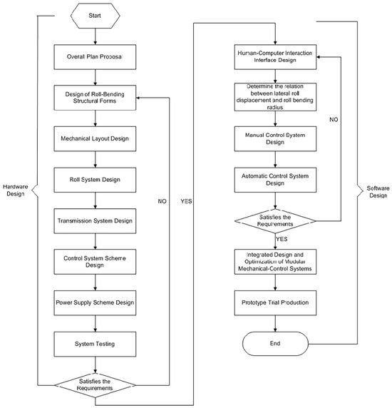
Figure 1.
Technical Roadmap of the Four-Roll Bending Machine.
A PC-based multi-axis controlled vertical four-roll bending machine was designed based on the requirements of bent components and the overall architecture of the rolling machine. The machine primarily consists of working rolls, a base frame, guide devices, a spindle drive system, side roll drive systems, lower roll drive systems, a drive system, a measurement and control system, and a transmission system, with its overall 3D mechanism illustrated in Figure 2. Equipped with an industrial control computer as the core control unit, the machine enables dual-mode operation through an integrated human–machine interface (HMI). In manual mode, operators can directly adjust the axial displacement of the side rolls via the interface to precisely execute single-pass rolling processes. When switched to automatic mode, the system supports parameterized input of target curvatures, automatically calculating and controlling the coordinated movement of all actuators based on predefined mathematical models to achieve high-precision single-pass rolling of metal profiles. This control architecture ensures stable process execution through real-time position feedback from servo cylinders and spindle photoelectric encoders, coupled with the real-time responsiveness of the servo system, thereby significantly enhancing machining efficiency and process repeatability.
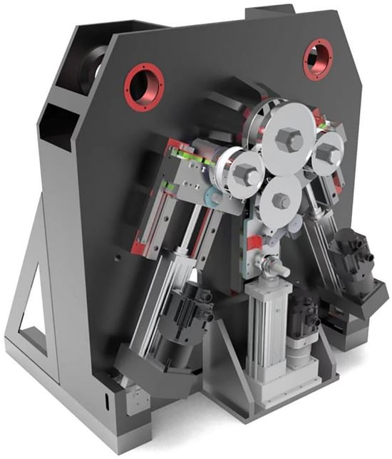
Figure 2.
3D Model of the Entire Machine.
Based on the functional positioning and process requirements of the rolling machine in the material forming process, the technical specifications formulated for the rolling machine are presented in Table 1.

Table 1.
Main Technical Specifications of the Four-Roll Bending Machine.
2.2. Roll Bending Working Principle and Technological Process Working Principle
As shown in Figure 3, the roll bending forming process of the vertical four-roll CNC roll bending machine is achieved through the coordinated action of the driving wheel (upper roller), lower roller, and two side rollers. Among these components, the driving wheel serves as the power source, propelling the profile forward through friction in conjunction with the lower roller. The left and right side rollers move along directions AA’ and BB’, respectively, enabling dynamic regulation of the profile’s forming radius by precisely controlling the spatial positions of the side roller pivots O3 and O4.
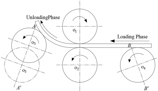
Figure 3.
Working Principle Diagram.
2.3. Technological Process
The four-roll roll bending forming technological process comprises four core procedures: Firstly, clamping and centering is performed on the profile, followed by pre-bending forming operation on the clamped and centered profile. During pre-bending forming, the left roller is driven by a servo-electric cylinder to descend until it reaches the same horizontal level as the vertex of the lower roller’s periphery, while the right roller is simultaneously lifted to a preset pre-bending forming height. After the roller system’s position and posture are adjusted properly, the driving wheel initiates rotation, utilizing the friction torque between the rollers and the profile to continuously roll-bend the profile until it reaches the left working roller’s position, thereby completing the initial pre-bending. Subsequently, the process enters the continuous roll bending stage: the right working roller is driven to descend to the roll bending forming height, and the left working roller is synchronously elevated to the processing position and posture. Once the spatial configuration of the roller system reaches the target state, the driving wheel rotates clockwise, and through sustained friction, it propels the profile to undergo plastic deformation circumferentially until the preset curvature requirement is met. Finally, an unloading operation is executed: when the trailing end of the profile advances to the centerline position of the lower working roller, the control system automatically triggers the unloading command, driving the left and lower rollers to descend synchronously to complete the profile unloading. After the profile is completely detached from the roller system, the rotation of the driving wheel is stopped, marking the completion of the entire roll bending forming technological process. The technological process is illustrated in Figure 4.
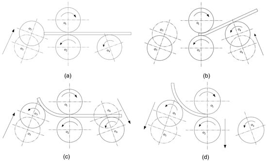
Figure 4.
Process Flow: (a) Clamping and Centering; (b) Pre-bending; (c) Roll Bending; (d) Unloading.
3. Design
3.1. Roller System Layout
This study compared various layout configurations for a four-roll bending machine and ultimately selected a symmetrical layout. This configuration strictly adheres to the principle of equal bending moments in four-point bending, employing an upper roller as the fixed primary drive roller, a vertically adjustable lower roller, and synchronized side rollers moving along symmetrical trajectories. This design ensures uniform force distribution and symmetrical stress patterns in the workpiece, establishing the foundation for high-precision roll bending. Integrated with a photoelectric encoder real-time feedback system, the symmetrical layout enables precise control over displacement consistency between the side rollers, effectively compensating for springback and further enhancing process accuracy. Additionally, its modular design features high transmission efficiency and low failure rates, particularly avoiding accelerated equipment wear caused by uneven loading on single-side rollers in asymmetric layouts when processing ultra-thick plates. While asymmetric layouts theoretically allow complex curvature control, practical implementation reveals significantly increased workpiece distortion risks due to uneven force distribution, along with challenges in maintaining displacement consistency and excessive demands on CNC system responsiveness with extended system reaction times. Therefore, after comprehensive evaluation of technical principles, process accuracy, and equipment reliability, this research confirms the adoption of the symmetrical layout scheme. Based on specified technical parameters, the machine base (as illustrated in Figure 5) was designed with a side roller center distance of 408 mm, vertical roller center distance of 172 mm, and side roller inclination angle of 25°, incorporating dedicated mounting positions for all four rollers and guiding mechanisms.
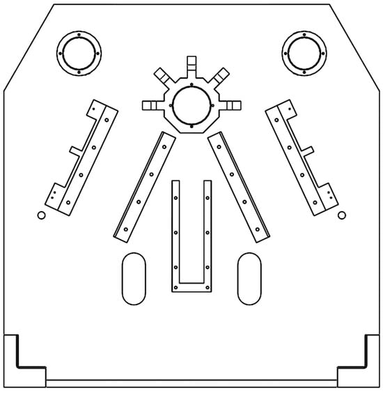
Figure 5.
CNC Four-Roll Bending Machine Base.
3.2. Guiding Mechanism
The primary function of the guiding mechanism is to provide guidance for the rollers and bear the load. The guiding mechanism designed in this study comprises two modules: the side roller guiding mechanism and the lower roller guiding mechanism, which, respectively, guide the side rollers and the lower roller, with the design of the guiding mechanism fully considering the requirement for easy disassembly. The side roller guiding mechanism consists of a side roller guide base, guide shaft 1, guide rail slider 1, and linear guide rail 1. Among these components, the side roller guide base is used to assemble the side roller, guide shaft 1, and guide rail slider, bearing the main load-bearing function. Guide shaft 1 is connected to the fish-eye bearing on the piston rod of the servo-electric cylinder, enabling the piston rod to drive the side roller guide base to displace along the guide rail during extension or retraction. The guide rail slider is connected to the side roller guide base, supporting its movement on the linear guide rail, while the linear guide rail ensures that the side roller guide base performs stable linear motion along the predetermined trajectory. The lower roller guiding mechanism consists of a lower roller guide base, guide shaft 2, guide rail slider 2, and linear guide rail 2. The components of the lower roller guiding mechanism are similar to those of the side roller guiding mechanism. However, the lower roller guiding mechanism is distinctively equipped with a photoelectric encoder. This photoelectric encoder accurately measures the rotation distance of the spindle and feeds back the feed distance of the profile, enabling precise monitoring of the feeding process. The three-dimensional structures are illustrated in Figure 6 and Figure 7.
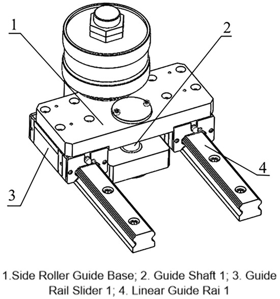
Figure 6.
Side Roller Guiding Mechanism.
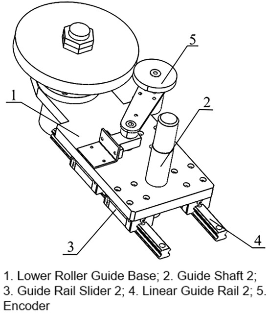
Figure 7.
Lower Roller Guiding Mechanism.
3.3. Force Analysis of the Pre-Bending Process
During the pre-bending operation of a four-roll bending machine, the two side rollers exhibit an asymmetric configuration, causing the line of action of force to rotate at a specific angle relative to the rolling operation. The geometric configuration under pre-bending conditions is illustrated in Figure 8.
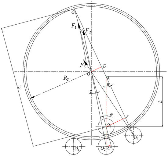
Figure 8.
Pre-bending Force Model.
When the forming radius decreases, the force acting on each roller increases. To accommodate the maximum design load, 45 steel is selected as the target material. According to the design specifications, when the forming radius is 1000 mm, the pre-springback neutral layer radius can be calculated as 799 mm using Equation (1).
where, denotes the radius before springback, denotes the radius after springback, T denotes the profile thickness, E denotes the elastic modulus, and denotes the yield strength. Section Modulus of the Profile:
where, H denotes the square of the profile height, and the profile height is 20 mm. Maximum Bending Moment for Deformation:
where, the relative strengthening coefficient is taken as 17.6, the cross-sectional shape coefficient is taken as 1.5, the thickness T of the rolled section is 20 mm, and the yield strength of 45 steel is 355 MPa. Length of the Residual Straight Edge [19]:
Therefore,
where, the diameter of the lower roller is 110 mm. In triangle :
Therefore,
where, the diameter of the upper roller is 110 mm. In triangle :
In triangle :
where, the tilt angle of the side roller is 25°. In triangle :
Therefore,
In triangle :
In triangle :
where, L is 323.81 mm. Therefore,
Simultaneous Equations (13) and (16):
Force on the Upper Roller ():
Force on the Lower Roller ():
Force on the Side Roller ():
3.4. Critical Component Simulation
Due to the maximum load borne by the lower roller guide mechanism during operation, it is necessary to conduct static stress, static displacement, and static strain analyses on the lower guide seat and connecting shaft. The guide seat primarily withstands pressure from the roller assembly and reaction forces from the connecting shaft, while the connecting shaft mainly bears support forces from the rod end bearings and counterforces from the guide seat. Both components are manufactured from Q235 steel with a yield stress of N/m². In this study, SolidWorks Simulation was used for static analysis. Loads were applied to the guide seat and connection shaft based on actual conditions. Approximately 1000 N load was applied to the guide seat, and approximately 900 N load was applied to the connection shaft. The results indicate: For the guide seat, the maximum stress of N/m² occurs at the junction with the connecting shaft and upper sleeve. Static displacement analysis reveals a maximum displacement of mm, while static strain analysis shows a peak strain of at the same connection points. For the connecting shaft, the maximum stress of N/m² is observed at the upper and lower fixed ends. Static displacement analysis identifies a maximum displacement of mm, and static strain analysis indicates a peak strain of at the fixed ends near the guide seat connection. Based on these static stress, displacement, and strain results, the designed lower roller guide mechanism demonstrates sufficient strength and stiffness under rolling conditions, meeting the design requirements. Detailed analysis diagrams are presented in Figure 9 and Figure 10.
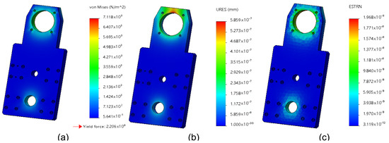
Figure 9.
Guide Seat Analysis: (a) Static Stress Analysis; (b) Static Displacement Analysis; (c) Static Strain Analysis.
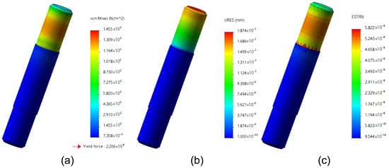
Figure 10.
Connecting Shaft Analysis: (a) Static Stress Analysis; (b) Static Displacement Analysis; (c) Static Strain Analysis.
3.5. Roll Bending Simulation
To verify the feasibility of roll bending forming for symmetric roller configurations, this study established an explicit dynamic analysis model using the ABAQUS platform. In the model, the trajectory lines of the side roller and bottom roller are arranged at a 25° inclination angle. The rollers are defined as 45Cr alloy structural steel (modulus of elasticity 206 GPa, Poisson’s ratio 0.30, density 7850 kg/m³), while the profile material is selected as aluminum alloy 6063 (modulus of elasticity 67.4 GPa, Poisson’s ratio 0.33, density 2700 kg/m³). The contact friction coefficient between the rollers and the profile is defined as 0.5, and partial data on the relationship between yield stress and plastic strain for the profile material are shown in Table 2. Multi-step roll bending simulations were conducted by parametrically controlling the displacement of the side rollers (14 mm, 21 mm, and 26 mm). The meshing details are shown in Table 3 and Figure 11. As shown in Figure 11 and Table 4, the simulation results indicate: Within the specified displacement range, the roller system achieves stable progressive bending deformation, validating the geometric adaptability and process feasibility of the symmetric configuration. It is important to note that while these findings substantiate the rationality of the structural design, the actual bending accuracy requires further physical testing due to limitations inherent in the rigid body assumptions and idealized contact conditions of the simulation model.
Table 2.
Yield stress and plastic strain.
Table 3.
Grid division and distribution of nodes.
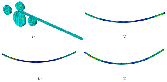
Figure 11.
Simulation Results: (a) Model mesh configuration; (b) Simulation results for 23 mm displacement; (c) Simulation results for 24 mm displacement; (d) Simulation results for 26 mm displacement.
Table 4.
Simulation Results: Side Roller Displacement and Bending Radius.
4. Control System Design
4.1. Roll Bending Control Requirements
The overall functional requirement block diagram of the roll bending machine control system is shown in Figure 12, with specific roll bending control requirements as follows.
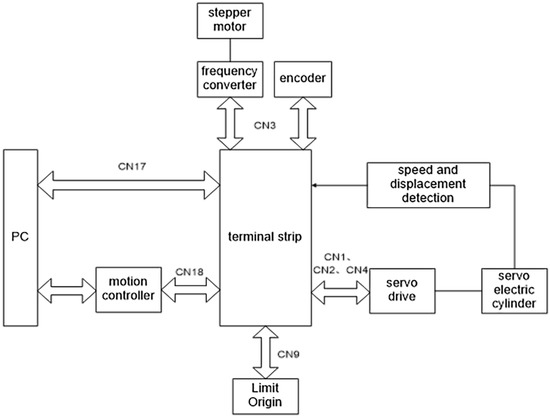
Figure 12.
Block Diagram of Roll Bending Control Requirements.
- (1)
- 3-channel digital signal servo driver interface, enabling communication between PC and servo driver, and converting digital signals into pulse signals for output to servo motors.
- (2)
- 1-channel digital signal interface for frequency converter and encoder, respectively achieving speed regulation of stepper motors and detection of spindle rotational position.
- (3)
- 12-channel I/O signal interfaces, enabling limit switch functionality, home position communication with host computer, and fault indication.
- (4)
- 1-channel CN17 BASIC PORT interface, enabling communication between PC and terminal boar.
- (5)
- 1-channel CN17 EXTEND PORT interface, enabling communication among PC, Googol controller, and terminal board.
4.2. Roll Bending Control System Module Division
The roll bending control system primarily consists of HMI, multi-axis motion control unit, drive system module, execution system module, work rolls, feedback module, etc. The block diagram of the four-roller roll bending machine control system modules is shown in Figure 13. Based on the control system requirements, the multi-axis motion controller selected is the Googol GTS-800, equipped with a terminal board. The drive system employs YLK parallel servo-electric cylinders and stepper motors, with the servo-electric cylinders driven by Delta ASDA-B3 servo drives. Among which, the stepper motor employs a three-phase power supply configuration with a 5.5 kW power rating, operates within a frequency range of 50/60 Hz, and is coupled with a GV-50 series gear reducer unit. The execution system includes drive shafts and ball screws: the stepper motor drives the spindle rotation via the drive shaft, while other rollers extend/retract through ball screw transmission. The feedback module utilizes OMRON E6B2-CWZ1X encoders for monitoring the rotational displacement of the drive roller, and encoders integrated with the servo-electric cylinders enable HMI-based monitoring of speed and displacement for all rollers. The HMI status monitoring interface provides real-time limit status checks for each roller. Interactions and functions between module components are detailed in Table 5. The control architecture achieves full servo-driven operation with ±0.01 mm positioning accuracy, outperforming conventional hydraulic/pneumatic systems. For real-time motion control, the GTS-800 motion controller handles motion planning and servo drive control, while the PC focuses on process logic and system status monitoring, forming a master-slave dual-core architecture with ≤0.05 mm synchronization error and ≤10 ms dynamic response time, ensuring system real-time performance.
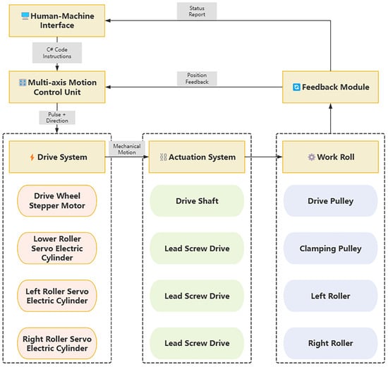
Figure 13.
Overall Architecture of the Four-Roll Bending Machine Control System.
Table 5.
Control Module Components and Functions.
4.3. Control Process
Based on the working principle and control requirements of the four-roll bending machine, its control process can be designed as a multi-feedback semi-closed-loop control system. Combined with a symmetric layout, it enables automated processing of plate bending and forming.
Manual Operation and Feedback: In manual mode, the HMI sends a single instruction to the motion controller for single-step control. Upon receiving the instruction, the motion controller executes the corresponding operation and sends feedback information identical to the instruction code back to the HMI. After receiving the feedback, the HMI confirms that the instruction has been successfully sent and executed.
Automatic Batch Instruction Execution: For complex bending tasks, a large number of control instructions can be pre-stored in an execution file. The motion controller reads and executes the instruction sequence in this file, thereby completing batch operation execution to realize an automated bending process. The control process of the four-roll bending machine is described below, as illustrated in Figure 14.
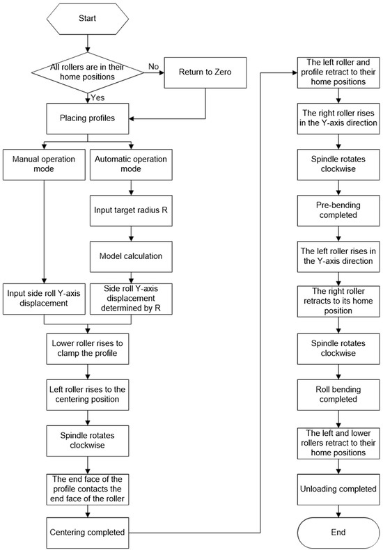
Figure 14.
Control Flow Chart.
Upon program initiation, the system first checks whether initialization and reset are completed and verifies if all rollers are at the home position. If not, manual homing is required. After homing confirmation, the profile is placed, and the system enters automatic bending mode with the preset radius R input. The system automatically calculates the side roller displacement Y based on its built-in mathematical model. The motion controller outputs a digital signal, which the servo driver converts into a pulse + direction signal to drive the lower roller servo cylinder, pushing the lower roller upward to clamp the profile. Simultaneously, the left roller servo cylinder pushes the left roller upward to the centering position, triggering the drive roller action command. The stepper motor drives the drive roller to rotate clockwise until the left end face of the profile contacts the left roller end face, completing centering and transitioning to the pre-bending phase. During pre-bending, the left roller servo cylinder retracts the left roller to its initial position, and the drive roller rotates counterclockwise to retract the profile. Subsequently, the right roller servo cylinder drives the right roller upward by displacement Y, and the stepper motor drives the drive roller to rotate clockwise until it reaches the left end of the left roller end face, completing pre-bending. The process then enters the bending stage: the right roller servo cylinder retracts the right roller to its initial position, while the left roller servo cylinder pushes the left roller upward by displacement Y, and the drive roller rotates clockwise until the profile is fully bent. After bending completion, the left and lower rollers return to their initial positions for unloading. Manual bending operation is largely consistent with automatic mode but requires manual input of the preset side roller displacement Y, with each operational step needing manual button confirmation by the operator. The drive roller rotation speed is set via HMI voltage adjustment.
This study adopts the post-springback radius–lateral roller displacement relationship model proposed by Jiang S et al. [20] as the mathematical description of the roll bending process, where the model expression can be formulated as:
where Y represents the lateral roller displacement and represents the roll bending radius.
4.4. Human–Machine Interface Design
This study employs a modular design approach to construct the human–machine interface system for a CNC four-roll bending machine, based on an in-depth analysis of its machining processes, mechanical structural characteristics, and operator requirements. The designed interface demonstrates enhanced maintainability, scalability, and readability. The HMI system is developed under the Windows 11 operating system using the Visual Studio 2022 integrated development environment, with a Windows Forms application framework implemented through the C# programming language. As a conventional desktop application format in C# development, this framework enables efficient interface design and development via the graphical interface designer provided by Visual Studio. The HMI system primarily consists of four modules: the logic control module, user interaction module, communication processing module, and database module. The logic control module is primarily responsible for handling complex control tasks within the HMI system, including system initialization and motion control of mechanical equipment. The user interaction module encompasses operations such as parameter configuration, data information display, request transmission to other modules, and system monitoring/maintenance. The communication processing module mainly facilitates communication between the HMI software and motion controller, managing data reception and transmission. The database module focuses on storing and retrieving various profile parameters and data involved in the HMI system. The HMI system of the CNC four-roll bending machine is equipped with a stop button on the status monitoring interface, and the manual operation interface and automatic operation interface are also equipped with motion stop buttons. In case of emergency, if the stop function of manual or automatic operation fails, the operator can use the stop button on the status monitoring interface or the servo shutdown button to terminate the motion, thereby ensuring operational safety. The interface architecture of the CNC four-roll bending machine HMI system is illustrated in Figure 15, with the main interface shown in Figure 16.
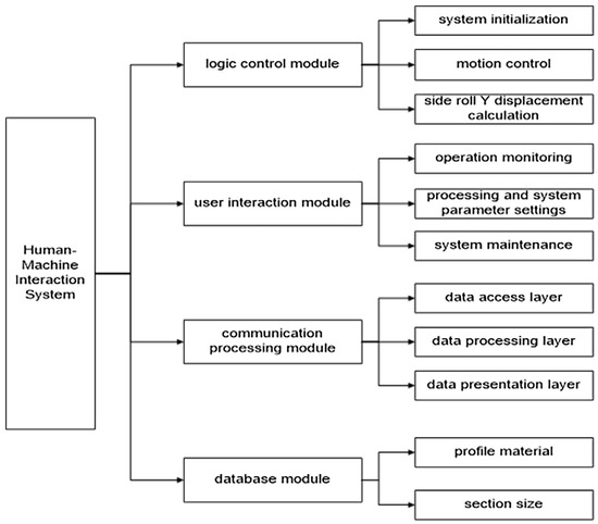
Figure 15.
Interface Architecture of the CNC Four-Roll Bending Machine Human–Machine Interaction System.
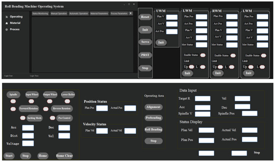
Figure 16.
Human-Machine Interface of CNC Four-Roll Bending Machine.
4.4.1. Logic Motion Control Module
In the operational process of the CNC four-roll bending machine, the operator establishes communication between the host computer and motion controller, utilizing the signal input/output functions of the motion controller to achieve real-time monitoring and precise control of roller/sensor statuses. When the servo cylinder is in an enabled state, the operator can initiate event response by pressing designated control buttons: upon receiving instructions, the motion controller promptly executes control operations, with the servo cylinder driving the rollers to specified positions to ensure accurate execution of bending motions. If the servo cylinder encounters a limit switch during movement, the system immediately activates the limit protection mechanism, halting cylinder motion and automatically disabling the corresponding axis to prevent equipment damage. After the limit condition is resolved, the operator may re-enable the corresponding axis to restore normal system operation. The motion logic control flow is illustrated in Figure 17.
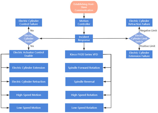
Figure 17.
Motion Logic Control Diagram.
4.4.2. User Interaction Module
The User Interaction Module comprises the following primary interfaces and functionalities: Manual Operation Interface: Primarily utilized for single-step control of various actuators while enabling real-time monitoring of detection mechanism statuses. This interface facilitates operator debugging, testing, and manual material processing operations on the rolling machine. Automatic Operation Interface: Allows configuration of processing parameters according to machining requirements and activation of automatic processing control functions to achieve automated bending of profiles.Status Monitoring Interface: Integrates two core functions: real-time operational status monitoring and system alarm management. The operational status monitoring function periodically refreshes (at 10 ms intervals by default) and displays real-time data transmitted by the motion controller during actual production processes. This ensures operators can promptly observe system communication statuses, actuator operational conditions, and component processing states. The system alarm function safeguards the integrity and reliability of the entire operational system by recording, storing, and visually presenting anomalies encountered during processing, thereby prompting operators to implement corrective actions based on real-time conditions.
4.4.3. Communication Processing Module
The Communication Processing Module is divided into three primary layers: the Data Access Layer, Data Preprocessing Layer, and Data Presentation Layer. The Data Presentation Layer is primarily responsible for integrating various functional requirements and providing interface APIs for other modules. It handles data received from external modules, executes instructions, and performs data processing. The Data Access Layer ensures a stable connection between the HMI and motion controller. In the HMI system of the CNC four-roll bending machine, the system is configured as the server, while the motion controller acts as the client, transmitting connection requests to the HMI. Upon receiving a connection request from the motion controller, the system triggers a signal to establish communication, thereby realizing data interaction with the motion controller.
4.4.4. Database Module
The database module of the CNC four-roll bending machine HMI serves as the central data hub, responsible for storing, managing, and retrieving critical parameters. It is deeply integrated with SQL Server Management Studio, providing standardized and intelligent data support for the bending processes.
Multi-dimensional Parameter Storage Functions: Roller Parameters: Records geometric parameters (diameter, roller clearance) and installation coordinates for the four rollers (main roller, side roller, support roller). Material Parameter Library: Stores mechanical property data (material code, name, elastic modulus, Poisson’s ratio, density, yield stress) for commonly used materials including carbon steel, stainless steel, and aluminum alloys, compliant with GB/T 228.1-2021 standards. Profile Parameter Library: Contains cross-sectional types (e.g., round tubes, square tubes, angle steel) and geometric dimensions (length, width, thickness) of profiles. Built-in SQL Query Engine: Supports rapid parameter retrieval based on material codes, profile sections, and other criteria.
The system adopts a relational database model with the following core table structures. A relational database model was employed to store multi-dimensional parametric data, with the specific content detailed in Table 6, Table 7 and Table 8.
Table 6.
Roller Parameters.
Table 7.
MaterialLibrary.
Table 8.
ProfileLibrary.
5. Experimental Validation
5.1. Experimental Validation of Machine Error
The machine error experiment aims to determine the magnitude of equipment error [21] in the four-roll bending machine, evaluating its geometric accuracy, motion stability, and forming error range. The experimental apparatus is shown in Figure 18a. To prevent excessively large roll bending radii from affecting the evaluation of machine error, this study conducted roll bending tests with different lateral roller displacements (10 mm, 15 mm, and 20 mm). This experiment employed a three-group repeated testing scheme: each group conducted three repeated rolling tests on 6063 aluminum alloy profiles (specifications: 20 mm × 20 mm × 1500 mm) under identical process parameters, yielding a total of 9 valid datasets as presented in Table 9. Analysis of the experimental data reveals that the equipment error remains within 1%, satisfying the rolling requirements. The rolled aluminum profiles from the experiment are displayed in Figure 18b. The roll bending radius is calculated using formula (23).
where: a is half of the chord length, and b is the sagitta (height of the arc).
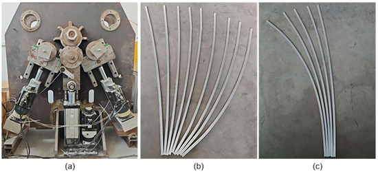
Figure 18.
(a) Four-Roll Bending Machine Schematic; (b) Test Profiles for Machine Error Experiment; (c) Test Profiles for Rolling Accuracy Experiment.
Table 9.
Analysis of Experimental Results for Machine Error.
5.2. Experimental Validation of Rolling Accuracy
To evaluate whether the rolling accuracy of the developed four-roll bending machine meets the requirements, this study conducted a rolling accuracy experiment. Based on the roller gap of the machine, aluminum profiles with specifications of 20 mm × 20 mm × 1500 mm were selected as the experimental material. To ensure the representativeness of the experimental results, five roll bending tests were conducted using preset radii of 1500 mm, 2000 mm, 2500 mm, 3000 mm, and 3500 mm, with each radius corresponding to one test. The experimental results, as shown in Table 10, include the measured actual bending radii and corresponding error values. The results indicate that the developed rolling machine achieves an average rolling error of 0.798% with an error range controlled within 0.84%, satisfying the precision requirements for profile rolling and aligning with the expected objectives. The test profiles used in this experiment are illustrated in Figure 18c. The roll bending accuracy error is defined by formula (24). To further evaluate the accuracy, comparisons were made between this machine and traditional roll bending machines, with relevant data presented in Table 11. The comparison indicates that the average error of traditional roll bending machines reaches 3.676%, which is relatively large and fails to meet the bending requirements for high-precision components. Therefore, the roll bending machine developed in this study demonstrates high accuracy and can satisfy the bending demands of high-precision components.
Table 10.
Analysis of Experimental Results for Rolling Accuracy.
Table 11.
Conventional Roll Bending Machine Roll Bending Results.
5.3. Arc Integrity Validation
In conventional roll bending processes, formed profiles commonly exhibit significant geometric residual straight edges at both ends. This phenomenon arises from the incomplete wrapping effect at the contact area between the upper roll and the workpiece. During operation of traditional roll bending machines, the length of the unformed end regions of the profile can reach up to 300 mm, as shown in Figure 19a. This parameter is influenced by the coupling effects of the machine’s structural parameters and the material’s mechanical properties. The fully servo-controlled four-roll bending machine developed in this study offers high precision, enabling real-time pose control during the rolling process. During the pre-bending stage, dynamic adjustment of the main spindle feed and side roll displacement significantly suppresses the geometric residual straight edges. Based on the experimental data from the profile rolling tests mentioned earlier, the maximum residual straight edge at the ends of the profiles formed using this machine is merely 40 mm, representing an 86.67% reduction compared to conventional equipment. This effectively ensures the geometric integrity of continuously bent profiles, meeting the stringent requirements for high-precision profile forming in aerospace and other advanced manufacturing fields.
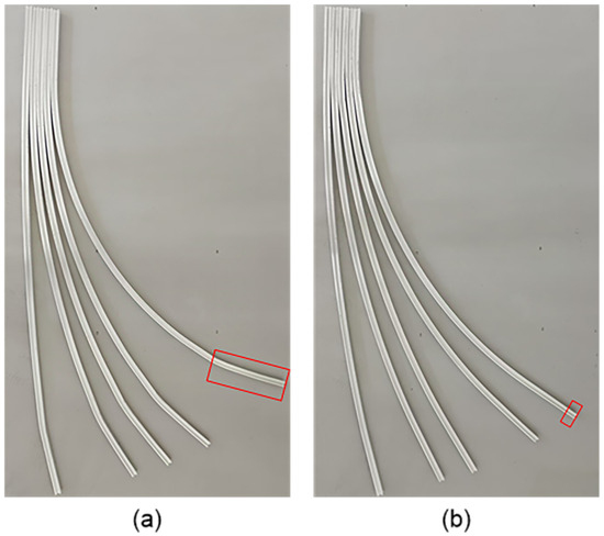
Figure 19.
Unilateral Residual Straight Edge Comparison: (a) Conventional Roll Bending Residual Straight Edge; (b) Proposed Machine Roll Bending Residual Straight Edge. The red boxes indicate the residual straight edge regions.
6. Discussion
This study systematically introduces the overall structure, workflow, and control architecture of a fully servo-controlled four-roll bending machine. The machine integrates a modular roll system architecture with a distributed multi-stage motion control system, enhancing equipment scalability and forming stability. The system employs a multi-axis control strategy that integrates the motion controller and servo drives. This approach achieves a positioning accuracy of ±0.01 mm. Experimental results demonstrate that the equipment maintains an error control within 1%, with an average rolling error of 0.798%. Compared to conventional roll bending processes, the residual straight edge length is significantly reduced, validating the effectiveness of the proposed solution. This machine offers advantages including high precision, intelligent operation, and excellent arc integrity, demonstrating broad application prospects in aerospace, rail transportation, and other advanced manufacturing sectors while providing robust support for high-end equipment production.
It is noteworthy that this study merely proposes and establishes a database conceptual framework covering partial profile specifications. Future research directions may focus on deeply integrating machine learning technologies, optimizing data integration within the database, and enhancing the real-time invocation mechanism of the machine towards the database. By incorporating machine learning algorithms, intelligent analysis and prediction of complex data generated during the roll bending process can be achieved, enabling dynamic adjustment of rolling parameters to further enhance bending accuracy.
7. Conclusions
In response to the urgent demand for high-precision bent parts in industrial manufacturing and the deficiencies of traditional roll bending machines in terms of forming accuracy, dynamic response, and process adaptability, this study proposes and develops a fully servo-driven four-roll roll bending machine based on C# programming, and experimentally verifies its roll bending accuracy. The primary contributions of this research include: designing a modular symmetric roller system structure, validating the strength of the guiding mechanism through SolidWorks Simulation static analysis to ensure high stiffness and dynamic load decoupling capability, with the maximum roll bending speed of the spindle reaching 23 r/min. Through ABAQUS explicit dynamics simulations, it is verified that under a 25° included angle, the symmetric axial roller layout exhibits stable progressive deformation capability and process feasibility in multi-displacement roll bending of aluminum alloy 6063 profiles. Furthermore, the deep integration of the modular mechanical platform with a distributed multi-level motion control system significantly enhances the equipment’s scalability and forming stability. Based on multi-axis control using a Googol controller and Delta servo drives, a development scheme for a fully servo-driven four-roll roll bending machine system is proposed, achieving a positioning accuracy of ±0.01 mm, which significantly surpasses traditional hydraulic and pneumatic drive methods and effectively guarantees the roll bending accuracy of profiles. Experimental verification indicates that the equipment error of this machine is less than 1%, with an average error of 0.798% for roll bending operations with different radii, reducing the residual straight edge length by 86.67% compared to conventional equipment.
Author Contributions
Conceptualization, D.G. and Q.S.; methodology, D.G. and Y.J.; software, D.G. and S.J.; validation, D.G., Q.S. and Y.Z.; data curation, D.G.; writing—original draft preparation, D.G.; writing—review and editing, Q.S.; visualization, Y.Z.; supervision, Q.S.; project administration, Q.S.; funding acquisition, Q.S. All authors have read and agreed to the published version of the manuscript.
Funding
Liaocheng’s key R&D plan was developed to create a special project to tackle common technical problems (No. 2021GGJBG005).
Institutional Review Board Statement
Not applicable.
Informed Consent Statement
Not applicable.
Data Availability Statement
No new data were created or analyzed in this study. Data sharing is not applicable to this article.
Conflicts of Interest
The authors declare no conflict of interest.
References
- Hua, M.; Baines, K.; Sansome, D. Design and Performance Considerations of the Continuos Four-roll Bender: A Precision Machine for the Roller Bending of Plates. In Proceedings of the Progress in Precision Engineering: Proceedings of the 6th International Precision Engineering Seminar (IPES 6)/2nd International Conference on Ultraprecision in Manufacturing Engineering (UME 2), May, 1991 Braunschweig, Germany; Springer: Berlin/Heidelberg, Germany, 1991; pp. 277–289. [Google Scholar]
- Corona, E. A simple analysis for bend-stretch forming of aluminum extrusions. Int. J. Mech. Sci. 2004, 46, 433–448. [Google Scholar] [CrossRef]
- Pham, C.; Thuillier, S.; Manach, P.Y. Twisting analysis of ultra-thin metallic sheets. J. Mater. Process. Technol. 2014, 214, 844–855. [Google Scholar] [CrossRef]
- Cha, W.g.; Kim, N. Study on twisting and bowing of roll formed products made of high strength steel. Int. J. Precis. Eng. Manuf. 2013, 14, 1527–1533. [Google Scholar] [CrossRef]
- Frohn-Sörensen, P.; Hochstrate, W.; Schneider, D.; Schiller, M.; Engel, B. Incremental bending of conic profiles on CNC hydraulic bending machines. Proc. Inst. Mech. Eng. Part B J. Eng. Manuf. 2021, 235, 1248–1268. [Google Scholar] [CrossRef]
- Wang, Z.; Hu, Y.; Cao, K.; Xu, M.; Hu, Y.; Sun, S. Optimized design of hydraulic and control system for longitudinal beam CNC bending machine. J. Phys. Conf. Ser. 2024, 2862, 012011. [Google Scholar] [CrossRef]
- Garad, S.; Ahire, S.; Gaidhani, A.; Bagul, P.; Kakade, D.A. Design and Development of Automatic Bending Machine. Int. J. Eng. Res. Technol. (IJERT) 2020, 9, 1375–1378. [Google Scholar]
- Amiolemhen, P.E.; Abiegbe, J.K. Design and fabrication of a three-rolls plate bending machine. Methodology 2019, 10, 31–41. [Google Scholar]
- Jing, Y.; Jiang, S.; Sun, Q.; Zhao, Y.; Song, Z.; Meng, X.; Li, H. Design and development of high precision four roll CNC roll bending machine and automatic control model. Sci. Rep. 2023, 13, 12954. [Google Scholar] [CrossRef] [PubMed]
- von Atzigen, M.; Liebmann, F.; Cavalcanti, N.A.; Baran, T.A.; Wanivenhaus, F.; Spirig, J.M.; Rauter, G.; Snedeker, J.; Farshad, M.; Fürnstahl, P. Reducing residual forces in spinal fusion using a custom-built rod bending machine. Comput. Methods Programs Biomed. 2024, 247, 108096. [Google Scholar] [CrossRef] [PubMed]
- Goto, H.; Tanaka, Y.; Ichiryu, K. 3D Tube Forming and Applications of a New Bending Machine with Hydraulic Parallel Kinematics. Int. J. Autom. Technol. 2012, 6, 509–515. [Google Scholar] [CrossRef]
- Gaaia, M.; Petcu, P.; Nicolau, A.M. Analysis of a roll bending machine: Enhancing efficiency and functionality. J. Ind. Des. Eng. Graph. 2024, 19, 29–32. [Google Scholar]
- Chen, P.; Lu, S. Springback characteristics and influencing laws of four-axis flexible roll bending forming for aluminum alloy. PLoS ONE 2024, 19, e0306604. [Google Scholar] [CrossRef] [PubMed]
- Liu, W.; Huang, K. Research on the three-roll-push-bending forming rulesfor improving processing precision. Int. J. Adv. Manuf. Technol. 2017, 90, 763–773. [Google Scholar] [CrossRef]
- Wu, K.; Sun, Y.; Cao, C.; Zhou, C.; Liu, Q.; Chang, X. On simulation analysis of plate forming and deformation compensation technology of the side roll for four-roll plate bending machine. Procedia Eng. 2017, 207, 1617–1622. [Google Scholar] [CrossRef]
- Hua, M.; Baines, K.; Cole, I. Bending mechanisms, experimental techniques and preliminary tests for the continuous four-roll plate bending process. J. Mater. Process. Technol. 1995, 48, 159–172. [Google Scholar] [CrossRef]
- Pachange, R.; Patil, A.; Naik, N.; Ajmani, N.; Bant, P.; Shivaprakash, M. Design And Fabrication Of Manual Roller Bending Machine. Int. Res. J. Eng. Technol. (IRJET) 2019, 7, 2278–2284. [Google Scholar]
- Gu, T.; Zhang, S.; Zhao, Y.; Yang, Y.; Liu, H.; Wu, L.; Liu, J.; Hou, H. Novel method to improve the microstructure and mechanical properties of 45 steel. Met. Mater. Int. 2022, 28, 833–840. [Google Scholar] [CrossRef]
- Yu, G.; Zhao, J.; Xu, C. Development of a symmetrical four-roller bending process. Int. J. Adv. Manuf. Technol. 2019, 104, 4049–4061. [Google Scholar] [CrossRef]
- Jiang, S.; Jing, Y.; Liu, H.; Sun, Q.; Zhao, Y. Theoretical and experimental analysis of springback compensation for four-roll roll forming. J. Braz. Soc. Mech. Sci. Eng. 2024, 46, 446. [Google Scholar] [CrossRef]
- Schwenke, H.; Knapp, W.; Haitjema, H.; Weckenmann, A.; Schmitt, R.; Delbressine, F. Geometric error measurement and compensation of machines—An update. CIRP Ann. 2008, 57, 660–675. [Google Scholar] [CrossRef]
Disclaimer/Publisher’s Note: The statements, opinions and data contained in all publications are solely those of the individual author(s) and contributor(s) and not of MDPI and/or the editor(s). MDPI and/or the editor(s) disclaim responsibility for any injury to people or property resulting from any ideas, methods, instructions or products referred to in the content. |
© 2025 by the authors. Licensee MDPI, Basel, Switzerland. This article is an open access article distributed under the terms and conditions of the Creative Commons Attribution (CC BY) license (https://creativecommons.org/licenses/by/4.0/).