Article

FEA for Optimizing Design and Fabrication of Frame Structure of Elevating Work Platforms

by
Antonio Berardi
1,*,
Cosimo Damiano Dellisanti
1,
Domenico Tarantino
1,
Karine Sophie Leheche Ouette
2,
Alessandro Leone
1 and
Antonia Tamborrino
1
1
Department of Plant, Soil and Food Sciences, University of Bari Aldo Moro, Via Amendola 165/A, 70126 Bari, Italy
2
Department of the Science of Agriculture, Food and Environment, University of Foggia, Via Napoli, 25, 71100 Foggia, Italy
*
Author to whom correspondence should be addressed.
Appl. Sci. 2025, 15(13), 7356; https://doi.org/10.3390/app15137356
Submission received: 19 May 2025 / Revised: 27 June 2025 / Accepted: 28 June 2025 / Published: 30 June 2025
(This article belongs to the Special Issue Innovative Engineering Technologies for the Agri-Food Sector)

Abstract

This study investigated the application of Finite Element Analysis (FEA) to optimize the design and material selection for the construction of the telescopic arm of an elevating work platform (EWP) used in agricultural environments. By comparing the structural performance of four materials—Aluminum Alloy (EN-AW 1200), Aluminum Alloy (EN-AW 2014), High-Strength Low-Alloy (HSLA) Steel Fe275JR, and HSLA Steel S700—under simulated operational conditions, this research identified the most suitable material for robust yet lightweight platforms. The results revealed that HSLA Steel S700 provides superior performance in terms of strength, low deformation, and high safety factors, making it ideal for scenarios requiring maximum durability and load-bearing capacity. Conversely, Aluminum Alloy (EN-AW 2014), while exhibiting lower strength compared with HSLA Steel S700, significantly reduces platform weight by approximately 60% and lowers the center of gravity, enhancing maneuverability and compatibility with smaller, less powerful tractors. These findings highlight the potential of FEA in optimizing EWP design by enabling precise adjustments to material selection and structural geometry. The outcomes of this research contribute to the development of safer, more efficient, and cost-effective EWPs, with a specific focus on improving productivity and safety in agricultural operations such as pruning and harvesting. Future work will explore advanced geometries and hybrid materials to further enhance the performance and versatility of these platforms.

1. Introduction

Elevating Work Platforms (EWPs) are essential tools across a wide range of industries, including construction, maintenance, manufacturing, warehousing, and increasingly, agriculture [1]. These platforms provide safe and efficient access to elevated work areas, allowing workers to perform tasks that would otherwise be challenging or dangerous [2]. Common types of EWPs include scissor lifts, boom lifts (both articulating and telescopic), and vertical mast lifts, each designed to meet the specific needs of different operational environments. Scissor lifts are frequently used in confined spaces for vertical lifting tasks, such as indoor maintenance. Boom lifts, with their extendable arms, are ideal for tasks that require a longer horizontal reach, making them popular in building maintenance and utility work. Vertical mast lifts, known for their compact size and maneuverability, are suited to narrow areas, such as warehouses and industrial storage facilities.
In agriculture, EWPs are increasingly used for tasks such as pruning, harvesting, and maintenance of orchards and plantations [3]. Boom lifts and scissor lifts are particularly valuable for reaching high branches during tree pruning, ensuring that workers can trim and maintain plants at significant heights safely and efficiently. Recently, a study [4] explored the use of EWPs in olive tree pruning, introducing a mechanized pruning system equipped with an elevated work platform with a double extendable arm, carried using the three-point hitch of the tractor. This study emphasized that agricultural EWPs, when properly designed and equipped, can transform labor-intensive tasks into safer, faster, and more efficient processes, thereby increasing productivity and reducing the need for manual ladder work.
In traditional olive growing, where trees can reach up to 10 m in height, EWPs offer significant advantages over ladders in pruning operations. A study by [5] compared mobile elevated work platforms with ladders in olive tree pruning, demonstrating that EWPs reduce physical strain on workers and improve pruning efficiency, making them a safer and more effective alternative. By reducing repetitive and strenuous movements required for pruning at heights, EWPs contribute to lower worker fatigue and a reduced risk of musculoskeletal injuries, which is especially important in physically demanding agricultural tasks.
However, agricultural applications of EWPs present unique challenges that require specialized design and material selection to ensure both structural integrity and operational efficiency. EWPs used outdoors must endure uneven terrain, environmental exposure, and dynamic loads associated with movement and pruning tasks [6,7]. These conditions demand frames that are not only robust enough to withstand repeated use but also lightweight for easy maneuverability.
The structural frame of an EWP is critical to its safety, stability, and functionality, as it must support variable loads while withstanding both static and dynamic forces during operation. Material selection, therefore, becomes a key aspect of frame design, directly influencing the platform’s strength, durability, weight, and overall performance. In agriculture and other demanding environments, selecting the right materials can make the difference between a safe, efficient platform and one prone to failure. Strong materials can improve stability and support heavier loads, but they often add weight, which may reduce maneuverability and increase operational costs. Conversely, lighter materials enhance mobility and efficiency but may compromise structural integrity if not adequately reinforced [8].
Finite Element Analysis (FEA) has become an essential tool for optimizing material selection and frame design in EWPs [9,10,11]. FEA enables the simulation of the behavior of different materials under various loading conditions, as defined by UNI EN 280 standards [12], identifying the most suitable materials for each type of EWP based on expected usage scenarios [13,14,15]. For agricultural applications, FEA can analyze the impact of dynamic forces—such as those generated during pruning—and select materials that maximize the strength-to-weight ratio while withstanding outdoor conditions [16].
Recent developments in boom design have further advanced the use of FEA for structural optimization. Comparative analysis had been conducted on telescopic booms with square and hexagonal cross-sections using ABAQUS [17]. The results showed that hexagonal profiles offered superior load-bearing performance while reducing structural weight, highlighting the potential of geometric refinement for enhancing strength and minimizing material usage in mobile structures.
In a separate application [18,19,20], ANSYS-based FEA was used to evaluate structural weaknesses in a three-point hitch agricultural cultivator. The study effectively identified high-risk zones under field conditions, demonstrating how simulation can inform material reinforcement and design optimization for rugged terrain machinery.
Despite the extensive use of FEA in industrial and construction EWPs, its application to agricultural platforms—specifically the telescopic arm design—has received limited attention [21,22]. This study addresses this gap by applying FEA to analyze and compare the structural performance of four materials commonly considered in EWP construction: two Aluminum Alloys (EN-AW 1200 and EN-AW 2014) and two High-Strength Low-Alloy Steels (Fe275JR and S700).
The main objectives of this research were (1) to identify stress concentrations and potential failure points in the telescopic arm under various loads typical of agricultural use; (2) to select the material that offers the best combination of strength, durability, and weight efficiency; and (3) to provide insights that can guide manufacturers in developing EWPs that are both safe and practical for agricultural operations.
In this study, the analysis of wind load was prioritized, as wind represents a significant external factor affecting the stability and safety of EWPs, especially in outdoor agricultural settings. According to UNI EN 280, wind load can critically influence the platform’s structural behavior during field operations, making it a key design consideration. Compared with other load conditions—such as platform weight and nominal user loads—wind load introduces unpredictable and dynamic lateral forces that critically affect the platform’s structural behavior. While dead loads act vertically and remain constant, wind loads induce bending, torsional, and shear stresses, especially at the fully extended arm. Moreover, in agricultural environments, wind conditions can change rapidly and unpredictably, making this factor even more relevant than typical operational loads in ensuring safety and structural integrity during pruning operations. By focusing on wind load, this research ensures that the telescopic arm design can maintain stability and performance even under adverse weather conditions, a crucial aspect for agricultural EWPs, which often operate in open, unpredictable environments.
By focusing on these research questions, this study aimed to fill an important gap in the literature and provide practical recommendations for the design of safer, lighter, and more efficient agricultural EWPs.

2. Materials and Methods

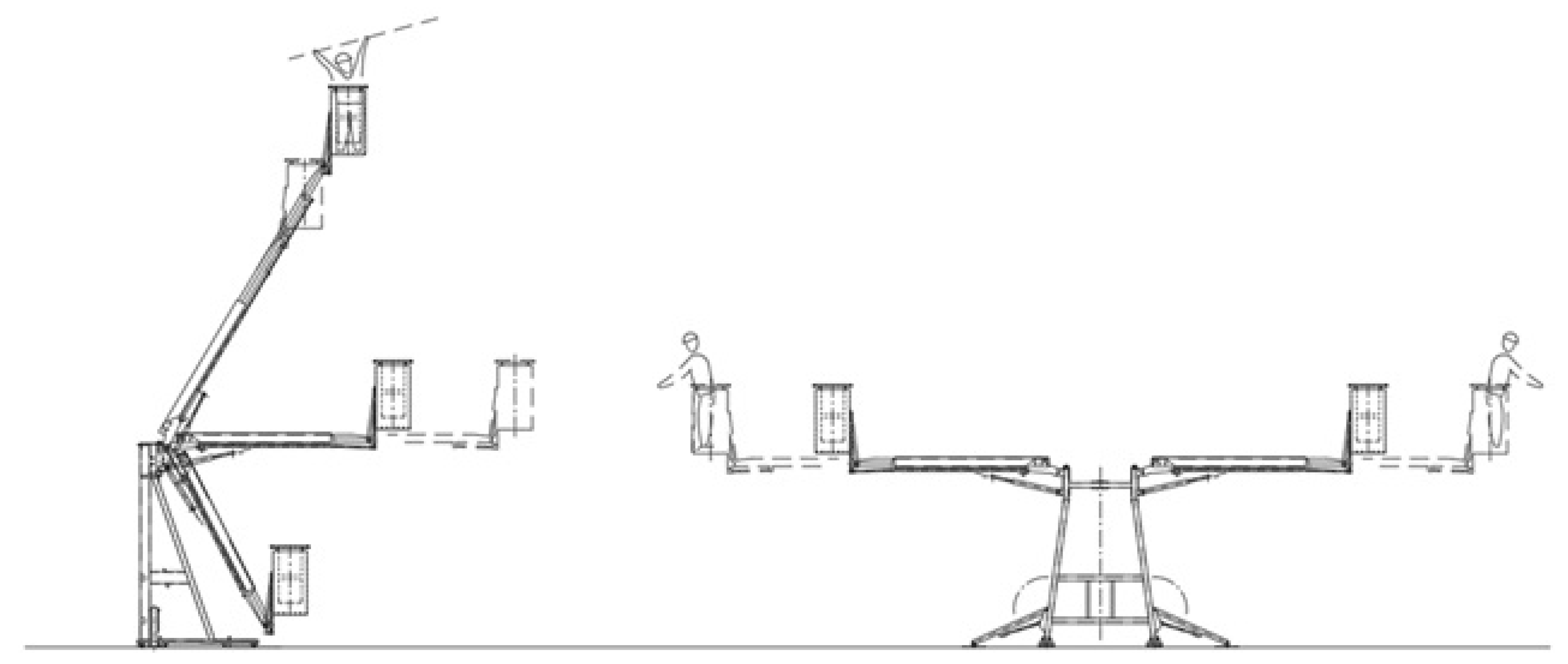
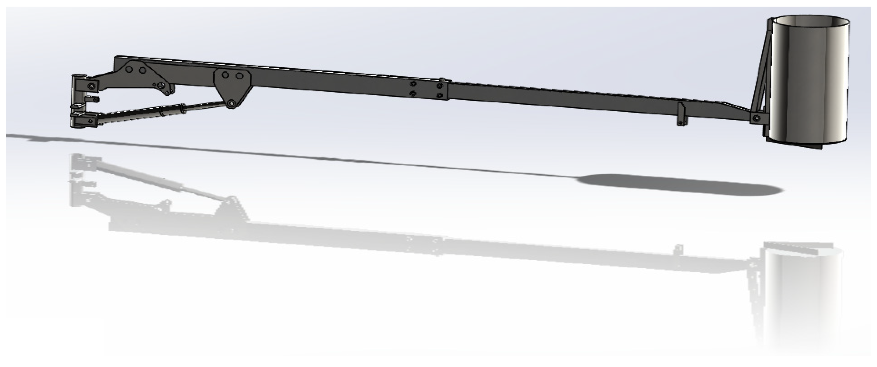
2.1. Experimental Design

This study applied Finite Element Analysis (FEA) to examine the structural performance of the telescopic arm frame of an Elevating Work Platform (EWP) constructed with four different materials, in accordance with UNI EN 280 (Figure 1). The objective was to identify the optimal material based on stress distribution, deformation, and load-bearing capacity under simulated operational conditions and the own weight of the structure in order to make it more manageable during transport and handling phases. The materials selected for this study include the following:
1.
Aluminium Alloy (EN-AW 1200): good resistance to corrosion, but not high resistance to stress. Known for its relatively low cost, mild steel offers moderate strength and ductility, making it a common choice in EWP frames;
2.
Aluminium Alloy (EN-AW 2014): Alloy highly appreciated for aeronautical and mechanical constructions where good toughness and good resistance to crack propagation are required;
3.
High-Strength Low-Alloy Steel (Fe275JR): structural steel with a low carbon content. Also called “construction steels”, as they are mainly used in the construction of building works;
4.
High-Strength Low-Alloy Steel (S700): structural steel. High strength low alloy for cold forming. Exceptional weldability properties. Excellent load-bearing capacity.
The analysis follows a structured approach to evaluate how each material affects the overall performance, focusing on load distribution, safety factors, and deformation patterns under standard operating conditions.

2.2. Finite Element Model Development

A 3D model of the EWP frame was developed using SolidWorks version 2023 software based on a generic EWP design commonly used in industrial and agricultural applications. The telescopic arm was modeled as a continuous structure with variable geometry, rather than a strictly homogeneous cantilever beam, to reflect the realistic design that includes welds, reinforcements, and connections (Figure 2).
This approach allows the analysis to capture local stress concentrations and deformation patterns more accurately than assuming a uniform cantilever model. The model was refined to include detailed representations of the main telescopic arms, base structure, hinge points, joints, reinforcements, and their support structures. Critical features, such as weld seams, bolt connections, and bracket attachments, were explicitly modeled to capture stress concentrations and ensure realistic load transfer between sections, which are known to be critical areas where potential failures can occur. This approach enables the analysis to identify and evaluate the most critical regions under operational conditions.
After creating the model, it was imported into ANSYS Workbench for FEA, where specific meshing, boundary conditions, and load scenarios defined in the UNI EN 280 standard were applied.
1.
Meshing: The frame model was meshed with a combination of tetrahedral and hexahedral elements, with finer meshing applied to critical areas prone to stress concentration (e.g., joints and connection points). A mesh sensitivity analysis was conducted to ensure accurate results, with the final mesh configuration selected to balance precision and computational efficiency. The mesh data are in Table 1.
2.
Material Properties: Each material was defined based on its mechanical properties as listed in Table 2. While tensile strength is listed for each material as an indicator of ultimate strength, it is not directly applied as a boundary condition in the FEA simulation. Instead, the analysis uses Young’s Modulus, Poisson’s Ratio, Yield Strength, and Density sourced from material databases and technical literature to define elastic behavior and evaluate stress distribution and safety factors under operational loads.

2.3. Boundary Conditions and Loading Scenarios

The frame model was subjected to multiple loading conditions simulating real-world operational stresses encountered by EWPs according to UNI EN 280. These included the following:
1.
Platform weight: The weight of the platform is calculated by adding the weight of each individual component of the platform. It is calculated by the software on the basis of the volume, and the acting weight force is positioned at the center of gravity of the component.
2.
Rated load:
The nominal load m is the following:
m = n * mp + me,
where the following is true:
mp: 80 kg (mass of a person);
me: 40 kg (minimum mass of tools and material);
n: the number of people allowed on the work platform.
The mass of each person is assumed to act as a point load on the working platform and on any extension of the platform at a horizontal distance of 0.1 m from the upper inside edge of the upper handrail. The distance between the point loads must be 0.5 m (Figure 3). The mass of the equipment is assumed to act as a uniformly distributed load over 25% of the working platform plane. If the resulting pressure exceeds 3 kN m−2, the percentage of 25% can be increased to a value that gives a pressure of 3 kN m−2 (Figure 4). All of these loads are assumed to be placed in the locations that result in the most severe outcomes.
The analysis includes both vertical and horizontal loads at various angles, with particular focus on angles that maximize shear stresses in the telescopic arm, as per the expected operational scenarios during pruning tasks.
3.
Wind Load:
According to the UNI EN 280, all mobile elevating work platforms used outdoors are considered to be subjected to wind pressure of 100 N m−2, equivalent to a wind speed of 12.5 m s−1 (Beaufort scale 6). Wind load was selected as a key boundary condition because it is a significant external factor affecting the stability and safety of EWPs, especially in agricultural applications, where platforms often operate in open and unpredictable environments. Wind load directly influences the lateral stability of the telescopic arm and was, therefore, prioritized for detailed analysis. Although other factors like ground inclination and operator motion can also influence stability, wind load is standardized and universally applicable under UNI EN 280, making it the most representative external factor for this study.
Wind stresses are assumed to act horizontally in the center of the area of the mobile elevating work platform parts, people and equipment on the working platform and should be considered as dynamic stresses.
Shape coefficients applied to areas exposed to wind:
(a)
L, U, T, I section: 1.6;
(b)
Box sections: 1.4;
(c)
Large flat areas: 1.2;
(d)
Circular sections, based on size: 0.8/1.2;
(e)
People directly exposed: 1.0.
The entire surface area of a person must be 0.7 m2 (0.4 m average width, 1.75 m height), with the center of the area 1.0 m above the level of the working platform.
The exposed area of a person standing on a working platform behind an unperforated section of fencing 1.1 m high shall be 0.35 m2, with the center of the area 1.45 m above the plane of the working platform.
The number of people directly exposed to the wind must be calculated as follows:
(a)
The length of the side of the working platform exposed to the wind, rounded to the nearest 0.5 m, and divided by 0.5 m;
(b)
The number of people admitted on the work platform, if less than the number calculated in (a).
The wind force on tools and materials exposed on the working platform shall be calculated as 3% of their mass, acting horizontally at a height of 0.5 m above the level of the working platform.
The applied loads are shown in Table 3.

2.4. Analysis Procedure
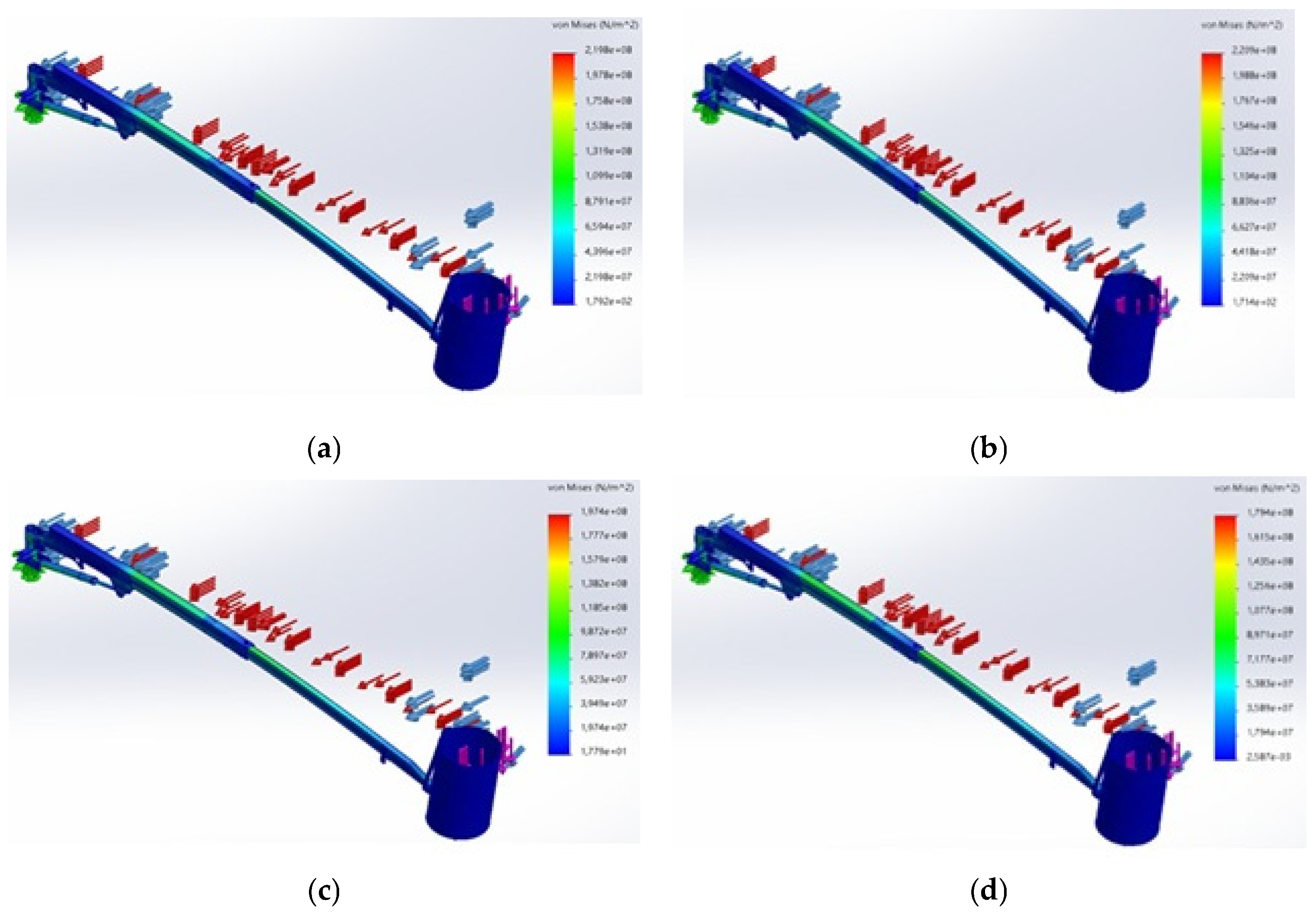
The analysis was conducted in ANSYS with the following steps:
1.
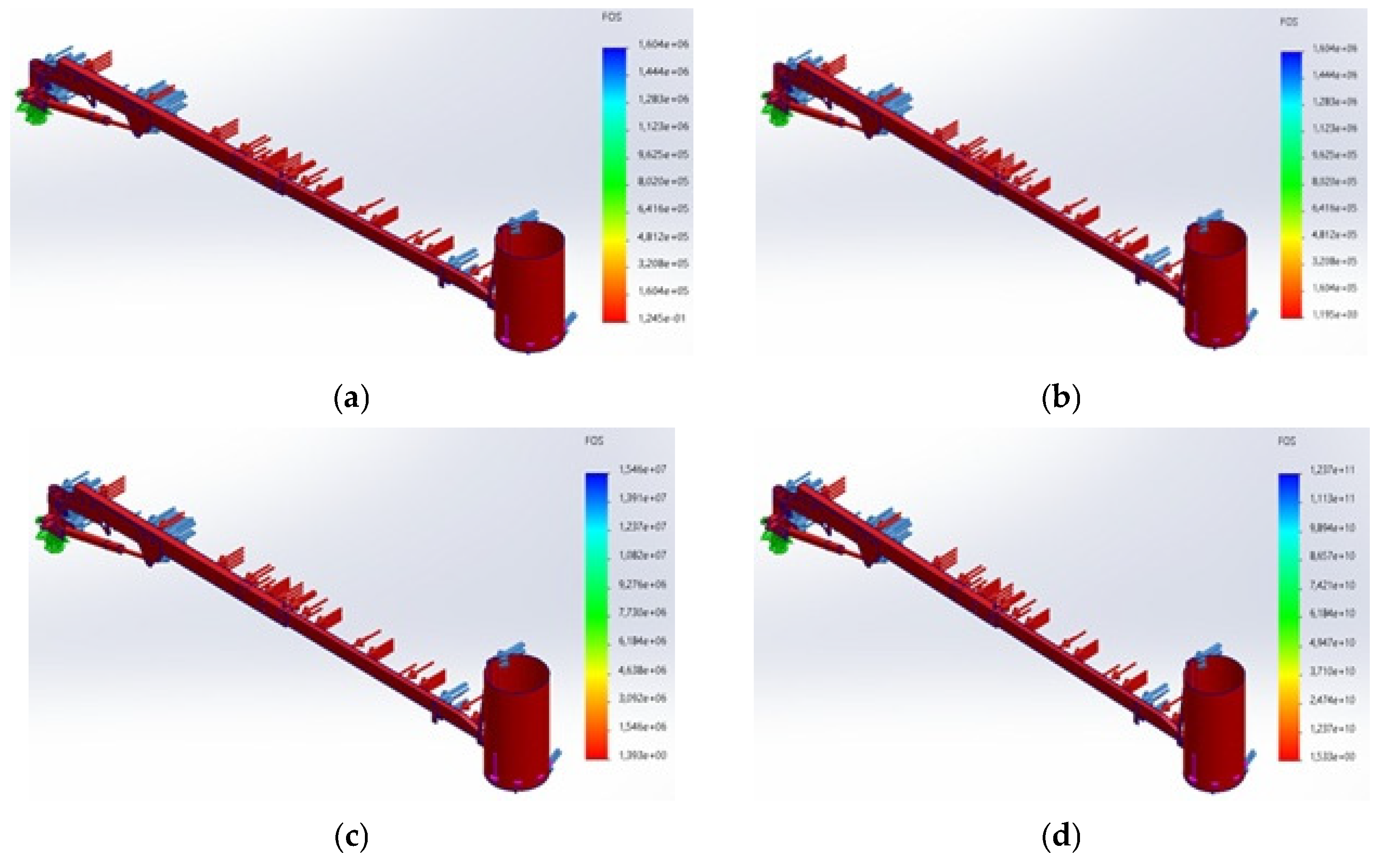
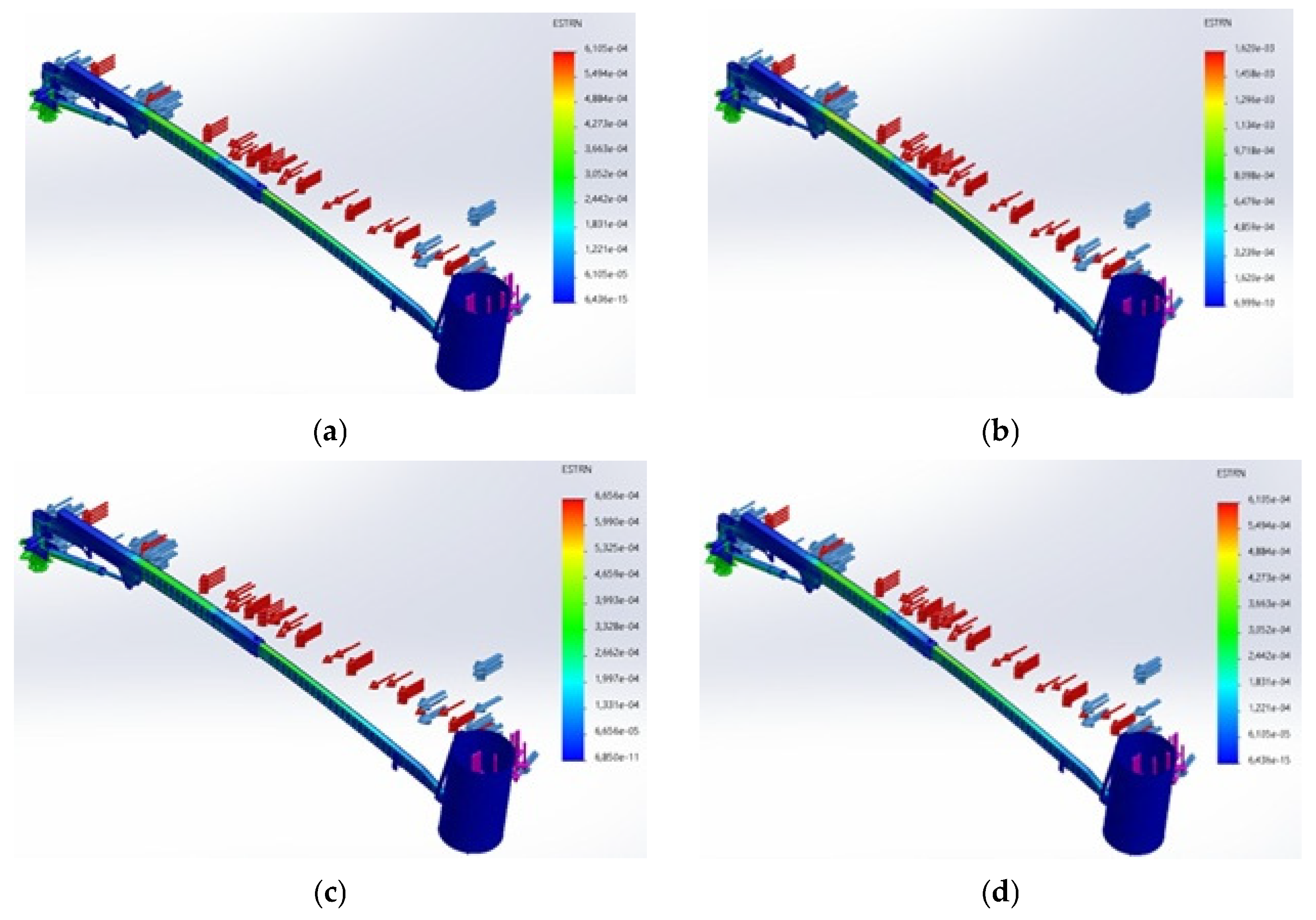
Static Structural Analysis: For each material, a static structural analysis was performed to calculate stress distribution, deformation, and factor of safety (FOS) under static and dynamic loading scenarios. The analysis focused on identifying maximum von Mises stress locations and comparing them to each material’s yield strength to assess safety.
2.
Modal Analysis: A modal analysis was conducted to determine the natural frequencies and mode shapes of the frame. This analysis helps to identify any resonance issues when subjected to dynamic loads, ensuring that the selected material does not lead to unwanted vibrations or structural instability.
3.
Fatigue Analysis: Using the fatigue module in ANSYS, the frame’s durability under cyclic loading was evaluated for each material. The number of load cycles to failure was estimated to assess each material’s resistance to fatigue and predict the frame’s operational lifespan under repeated loads.
4.
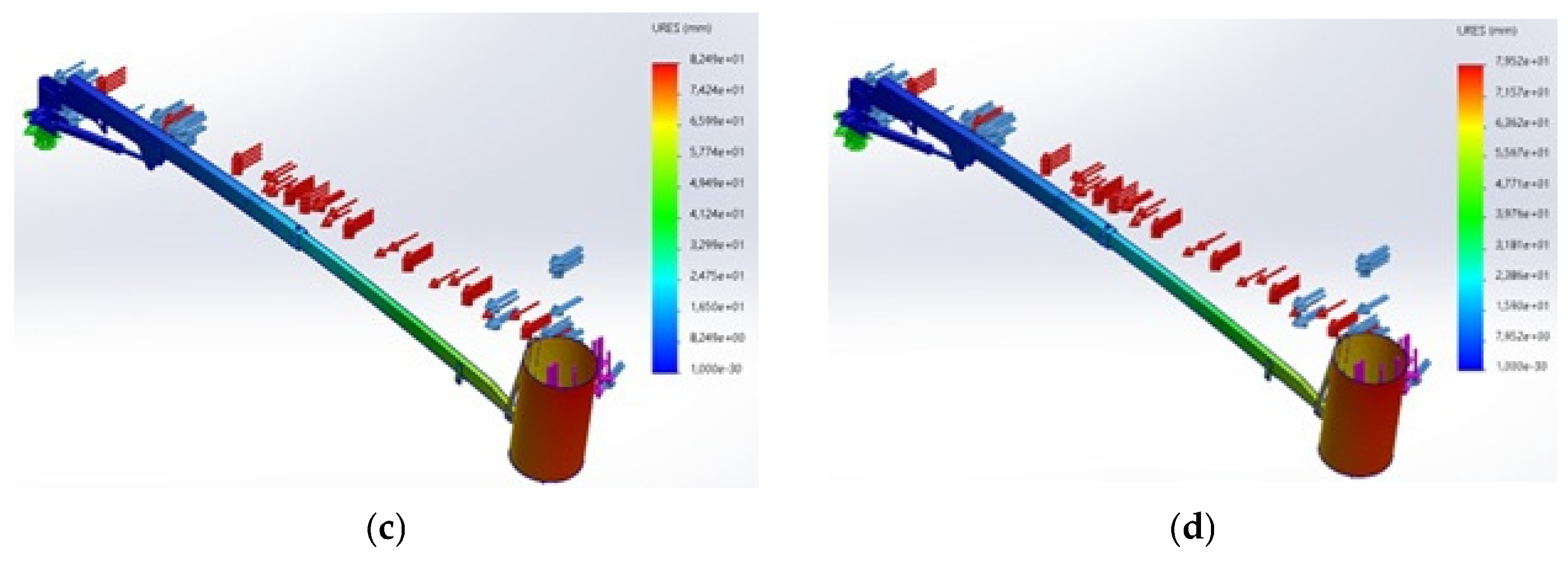
Deformation and Deflection Analysis: Deformation under loading was calculated to evaluate stiffness and resistance to bending. Excessive deflection was considered a potential failure criterion, as it could impact platform stability and operational safety. In addition to the magnitude of deformation, the direction of deformation vectors was analyzed to assess the risk of instability, tipping, or excessive lateral deflection. This directional analysis helps identify critical points in the structure that may compromise safety or maneuverability during agricultural operations.

2.5. Data Analysis and Comparison

The results for each material were compared across the following criteria:
  • Maximum Stress: The von Mises stress was calculated for each material under different load conditions and compared to the material’s yield strength to ensure safety;
  • Deformation: The maximum deflection under each load case was recorded, with materials showing lower deformation considered more favorable for stability;
  • Factor of Safety (FOS): The FOS was computed for each material to evaluate the frame’s margin of safety under applied loads.
The results for each material were analyzed to determine the optimal choice based on strength, durability, and weight–efficiency balance, providing insights into the most suitable material for EWP frames used in agricultural and industrial settings [16].

3. Results

3.1. Criteria Analisys for Evaluation

3.1.1. Comparative Analysis of Material Performance

The Finite Element Analysis (FEA) revealed significant differences in structural performance among the four materials—Mild Steel (A36), High-Strength Low-Alloy (HSLA) Steel, Aluminum Alloy (6061-T6), and Fiber-Reinforced Polymer (FRP). Table 4 summarizes the results, including maximum von Mises stress, deformation, factor of safety (FOS), and estimated fatigue life under cyclic loading [15,16,17].
The Aluminum Alloy arms were modeled with the same geometry and dimensions as the steel arms to ensure a consistent comparison of performance and stress distribution across materials, eliminating geometric variables that might otherwise affect the interpretation of material influence.
These results provide a solid basis for targeted geometry optimization, highlighting materials that exhibit lower stress concentrations and deformations, and pointing toward potential refinements—such as increasing local thickness in high-stress areas or optimizing cross-sections—to balance weight and strength effectively. Importantly, the analysis was conducted at the fully extended length of the telescopic arm, which represents the worst-case scenario for bending moments and shear stresses. This configuration is critical for design evaluation. If geometry were modified to adapt to different materials, the stress distribution would indeed change, suggesting that future studies should investigate geometry optimization strategies that leverage the unique properties of each material, potentially leading to lighter yet equally strong designs.

3.1.2. Stress and Factor of Safety (FOS)

Analyzing the results, it must be considered that the expected design loads are already increased with coefficients imposed by the current Uni EN 280 standard.
Analyzing the model created with Aluminum Alloy (EN-AW 1200), the Maximum Stress value of 219.8 MPa and the very low FOS value determine the inadequacy of this material for the intended use [18].
The models simulated with Aluminum Alloy (EN-AW 2014), HSLA Steel (700), and HSLA Steel (Fe275JR) present good strength and safety values, well within their yield strength. The high FOS indicates that the material can withstand unexpected dynamic loads or overloading conditions, a key advantage for agricultural applications.
Aluminum Alloy (EN-AW 2014) exhibited slightly higher stress (220.9 MPa) but maintained an FOS of 1.2. Due to the lower density value of aluminum, the entire system will be lighter.
HSLA Steel (Fe275JR) allowed FOS to increase up to 1.4, reducing the maximum stress (197.4 MPa) but increasing the structure weight, similarly to HSLA Steel (700), where the maximum stress is lower (179.4 MPa) and FOS is higher, 1.5.
Figure 5 compares the four different materials and the simulated Stress diagrams; similarly, Figure 6 compares the FOS calculated.

3.1.3. Deformation and Structural Stability

The FEA results show considerable variation in maximum deformation across the four materials, impacting each material’s suitability for different EWP applications [11].
The aluminum material, compared with HSLA steel, records greater deformations; in fact, HSLA steel (700) had a maximum deformation of 79.5 mm, and HSLA steel (Fe275JR) had a slightly greater with a value of 82.5 mm, while the alloy of aluminum (EN-AW 1200) records a maximum value of 231.8 mm and Aluminum Alloy (EN-AW 2014) had a similar value of 225.3 mm. While higher deformation values at the tip of the arm may be acceptable due to slow movement speeds and static operations, further analysis of local deformations can guide design adjustments to strengthen key areas, thus contributing to overall structural stability. Since the movement speed of the platform is very low and the execution of the activities takes place in static conditions, even a higher maximum deformation value, which is recorded at the tip of the arm, can be acceptable since it does not affect the stability of the support on which it is find the operator (Figure 7 and Figure 8).

3.1.4. Mass Comparison and Percentage Reductions

The Finite Element Analysis (FEA) on the four materials: Aluminium Alloy (EN-AW 1200), Aluminium Alloy (EN-AW 2014), High-Strength Low-Alloy Steel (Fe275JR), and High-Strength Low-Alloy Steel (S700) revealed significant mass differences up to 60%, impacting both maneuverability and compatibility with the tractor’s lifting system [19]. Table 5 shows the percentage mass reduction for each material compared with Low-Alloy Steel, the baseline with the highest mass.
Although the theoretical density ratio between steel (7800 kg m−3) and aluminum (2800 kg m−3) is about 2.78, the weight ratio of the two steel and aluminum models shows a mass ratio of 2.46; this result is justified by the fact that the connecting elements such as bolts, pins, etc. have been considered in all steel modeling.

3.1.5. Comparative Discussion and Practical Implications

The results indicate that HSLA Steel provides the best overall performance, balancing strength, low deformation, and extended fatigue life. As an alternative material for the application in agricultural purposes, mainly in pruning, we can apply the Alloy (EN-AW 2014). The performance of the material is less competitive compared with HSLA, but the weight of the platform, with similar geometry of the component, allows for reducing the load three-point linkage of the tractor by about 60% and to lower the center of gravity of the platform in static conditions [9,20,21].
Although the performance parameters of Alloy (EN-AW 2014) are acceptable in terms of safety, wanting to improve them and bring them closer to those of HSLA, one could think about redesigning the geometry of the arm, increasing the sections or thicknesses; although this operation may generate an increase in the weight of the structure, it would still guarantee a lower weight of the entire system.
Based on the FEA results, optimization strategies can be proposed by reinforcing local sections of the telescopic arm that experience higher stresses, using variable wall thickness or additional stiffening ribs. These strategies aim to maintain or enhance structural performance while still achieving weight savings. Additionally, targeted optimization could focus on fatigue-critical regions identified through modal and fatigue analyses.
The modal analysis revealed that the first three natural frequencies are sufficiently above the working frequency range, minimizing the risk of resonance during typical pruning operations. However, further investigation of mode shapes suggests potential local deformations near connection points that could be mitigated through design refinements. Fatigue analysis indicated that HSLA steels can endure significantly higher load cycles compared to aluminum alloys, aligning with their higher FOS and lower deformation, supporting their use in high-cycle operational scenarios typical of agricultural EWPs.
Overall, the analysis demonstrates that by selecting materials with favorable mechanical properties and optimizing the geometry accordingly, safer, lighter, and more cost-effective EWPs can be developed. Such improvements are essential in agricultural contexts where equipment must balance performance and efficiency. Future studies should integrate advanced optimization techniques (e.g., topology optimization) to refine the structure further and enhance field performance.
To further improve the structural behavior, future studies should apply advanced optimization techniques such as parametric optimization, sensitivity analysis, and topology optimization. These tools allow for a more accurate identification of critical parameters—such as wall thickness, reinforcement distribution, and joint stiffness—that most significantly influence stress concentrations and deflection. Moreover, multi-objective optimization algorithms could be used to simultaneously balance weight reduction, safety factor enhancement, and fatigue life extension, particularly under variable wind and service loads.

3.2. Field Maneuverability, Tractor Lifting Capacity, and Operational Efficiency

Pruning operations take place in fields where the distance between the rows is not always practicable with every type of tractor, and above all, it is not constant. Added to this is the conformation of the land, which is not always flat; therefore, to have good maneuverability, it is necessary to use medium–small power tractors, which, however, have reduced lifting capacity. Finally, to be able to carry out work even on slightly steep or irregular terrain, the lower center of gravity allows you to reduce the risk of lateral rollover [3,4].
The simulation of a telescopic arm using Aluminum Alloy (EN-AW 2014) demonstrated a significant weight reduction of approximately 60%. The weight reduction allows for the use of smaller, less powerful tractors compared to those currently in use, enabling more efficient lifting and movement of the EWP. Furthermore, the reduced weight, combined with a lower center of gravity, enhances the machine’s maneuverability and stability, thereby improving the safety of the worksite during field operations.

4. Conclusions

This study highlights the effectiveness of Finite Element Analysis (FEA) in optimizing the material selection and design of telescopic arms for Elevating Work Platforms (EWPs) used in agricultural applications. The comparison of four materials—Aluminum Alloy (EN-AW 1200 and EN-AW 2014), HSLA Steel (Fe275JR, and S700)—has led to the following key findings:
1.
HSLA Steel S700 emerged as the optimal material due to its superior strength, lower deformation, and high safety factor, making it ideal for demanding operational conditions requiring durability and load-bearing capacity.
2.
Aluminum Alloy (EN-AW 2014) provides a viable lightweight alternative, reducing the overall weight of the platform by approximately 60%. This weight reduction enables the use of smaller, less powerful tractors, improving maneuverability, lowering the center of gravity, and enhancing stability and safety during operations on uneven or sloped terrain.
3.
The use of FEA allowed for the identification of stress concentrations, deformation patterns, and failure points, enabling targeted improvements to the structural design without relying on time-consuming and costly physical tests.
The results also support targeted optimization strategies, such as reinforcing critical regions with higher local stress or introducing variable wall thicknesses and stiffeners, to improve safety and performance while maintaining weight advantages.
Modal and fatigue analyses confirmed that the selected materials, especially HSLA steels, perform well under dynamic and cyclic loading. However, further refinement of design details at connection points is recommended to mitigate localized vibration and fatigue risks.
This study demonstrated that integrating performance analysis, optimization strategies, and design improvements can result in safer, lighter, and more cost-effective EWPs that meet the demands of agricultural applications.
The findings highlight the potential to strike a balance between performance, safety, and practicality. Future studies should not only focus on geometry optimization and hybrid materials but also incorporate advanced simulation techniques (e.g., parametric and topology optimization) to fine-tune design parameters for different operational scenarios, including varying wind loads and dynamic conditions.
This work provides valuable insights for manufacturers and operators, supporting the development of safer, lighter, and more cost-effective EWPs tailored to the unique demands of agricultural environments.

Author Contributions

Conceptualization, A.T.; methodology, K.S.L.O.; software, A.B.; validation, C.D.D.; data curation, D.T.; writing—original draft preparation, A.B.; writing—review and editing, A.L. All authors have read and agreed to the published version of the manuscript.

Funding

This research received no external funding.

Institutional Review Board Statement

Not applicable.

Informed Consent Statement

Not applicable.

Data Availability Statement

The data presented in this study are available on request from the corresponding author.

Conflicts of Interest

The authors declare no conflicts of interest.

References

  1. May, F.; Spindler, B.; Müsse, J.; Skiba, K.; Kemper, N.; Stracke, J. Use of an elevated platform with perforated surface and manure belt by fast-growing broilers on commercial farms. Poult. Sci. 2024, 103, 103243. [Google Scholar] [CrossRef] [PubMed] [PubMed Central]
  2. Wang, Y.; Li, Z.; Wong, D.W.-C.; Cheng, C.-K.; Zhang, M. Finite element analysis of biomechanical effects of total ankle arthroplasty on the foot. J. Orthop. Transl. 2017, 12, 55–65. [Google Scholar] [CrossRef] [PubMed]
  3. Mohta, V.; Patnaik, A.; Panda, S.K.; Krishnan, S.V.; Gupta, A.; Shukla, A.; Wadhwa, G.; Verma, S.; Bandopadhyay, A. Design of an All-Purpose Terrace Farming Robot. arXiv 2022, arXiv:2212.01745. [Google Scholar] [CrossRef]
  4. Leone, A.; Amirante, P.; Tamborrino, A. Olive pruning mechanization system with a new type of elevated work platform. Acta Hortic. 2012, 949, 391–398. [Google Scholar] [CrossRef]
  5. Romaniello, R.; Tamborrino, A.; Leone, A. Mobile elevated work platforms versus ladders in olive tree pruning. J. Agric. Saf. Health 2018, 24, 141–153. [Google Scholar] [CrossRef] [PubMed]
  6. Kone, P.S.; Sengottain, S.; Murugan, S.; Harish, K. Stability Analysis of Self-propelled Aerial Man Lift Vehicles. Int. J. Veh. Struct. Syst. 2017, 9, 276–279. [Google Scholar] [CrossRef]
  7. Miomir, L.J.; Goran, N.; Stojanović, V.S. Accuracy of incidental dynamic analysis of mobile elevating work platforms. Struct. Eng. Mech. 2019, 71, 553–562. [Google Scholar] [CrossRef]
  8. Batista, E.; De Lazzari, J.A.; Matsubara, G.; Pfeil, M. Structural Dynamic and Buckling Behaviour of Steel Cold-formed Polygonal Conic Pole for Antennas Support. CE/Pap. 2022, 5, 151–160. [Google Scholar] [CrossRef]
  9. Velloso, N.S.; Costa, A.L.G.; Magalhães, R.R.; Santos, F.L.; Andrade, E.T. The Finite Element Method Applied to Agricultural Engineering: A Review. Curr. Agric. Res. J. 2018, 6, 286–299. [Google Scholar] [CrossRef]
  10. Cao, P.; Wang, T.; Zhai, L.; Niu, S.; Liu, L.; Shi, Y. Design of 6-DOF Tomato Picking Lifting Platform. Agriculture 2022, 12, 1945. [Google Scholar] [CrossRef]
  11. Sharma, A.; Bagha, A.; Shukla, D.; Bahl, S. Finite element model updating of metallic and composite structures-A state of the art review. AIMS Mater. Sci. 2021, 8, 390–415. [Google Scholar] [CrossRef]
  12. UNI EN 280:2013+A1:2015; Mobile Elevating Work Platforms—Design Calculations—Stability Criteria—Construction—Safety—Examinations and Tests. iTeh Standards: Newark, DE, USA, 2015.
  13. Bai, Z.; Lv, X.; Xia, L. Finite Element Analysis for the Lifting Platform of a Self-Propelled Multi-Functional Machine Used in Orchard. IOP Conf. Ser. Mater. Sci. Eng. 2019, 470, 012012. [Google Scholar] [CrossRef]
  14. Godara, S.S.; Brenia, V.; Soni, A.K.; Shekhawat, R.S.; Saxena, K.K. Design & analysis of connecting rod using ANSYS software. Mater. Today Proc. 2022, 56, 1896–1903. [Google Scholar] [CrossRef]
  15. Zhang, C.; Yang, J.; Jiang, L.; He, Y. Experimental Studies and Finite Element Analysis of Socket-Type Keyway Steel Pipe Scaffolding. Buildings 2024, 14, 245. [Google Scholar] [CrossRef]
  16. Liu, T.; Huang, Y.; Li, Y.; Meng, J.; Liu, Y.; Wei, Y.; Huang, Y.; Zhou, Q.; Yang, W.; Yan, F.; et al. Effect of different restorative design and materials on stress distribution in cracked teeth: A finite element analysis study. BMC Oral Health 2025, 25, 31. [Google Scholar] [CrossRef] [PubMed] [PubMed Central]
  17. Guo, H.; Mu, X.; Lv, K.; Du, F. Telescopic Boom Design and Finite Element Analysis Based on ABAQUS. Adv. Mater. Res. 2014, 1077, 215–220. [Google Scholar] [CrossRef]
  18. Yang, J. Strength Calculation Method of Agricultural Machinery Structure Using Finite Element Analysis. Int. J. Adv. Comput. Sci. Appl. 2024, 15, 699–705. [Google Scholar] [CrossRef]
  19. Gipiela, M.L.; Amauri, V.; Nikhare, C.; Marcondes, P.V.P. A numerical analysis on forming limits during spiral and concentric single point incremental forming. IOP Conf. Ser. Mater. Sci. Eng. 2017, 164, 012009. [Google Scholar] [CrossRef]
  20. Huang, J.; Tian, K.; Ji, A.; Zhang, B.; Shen, C.; Liu, H. Research on the Construction of a Finite Element Model and Parameter Calibration for Industrial Hemp Stalks. Agronomy 2023, 13, 1918. [Google Scholar] [CrossRef]
  21. Batista, E.; De Lazzari, J.A.; Matsubara, G.; Pfeil, M.; Elias, R. Assessment of reinforcements for enhancing structural performance of cold-formed steel polygonal conical poles for antennas support. Lat. Am. J. Solids Struct. 2025, 22, e8033. [Google Scholar] [CrossRef]
  22. Bagha, A.; Bahl, S. Finite element analysis of VGCF/pp reinforced square representative volume element to predict its mechanical properties for different loadings. Mater. Today Proc. 2020, 39 Pt 1, 54–59. [Google Scholar] [CrossRef]
Figure 1. Spaces for maneuvering a telescopic elevating work platform.
Applsci 15 07356 g001
Figure 2. 3D model FE of EWP frame.
Applsci 15 07356 g002
Figure 3. Mass person position as per UNI EN 280.
Applsci 15 07356 g003
Figure 4. Mass tools and material position as per UNI EN 280.
Applsci 15 07356 g004
Figure 5. Stress diagram (a) Aluminium Alloy (EN-AW 1200); (b) Aluminium Alloy (EN-AW 2014); (c) High-Strength Low-Alloy Steel (Fe275JR); (d) High-Strength Low-Alloy Steel (S700).
Applsci 15 07356 g005
Figure 6. Factor of safety diagram (a) Aluminium Alloy (EN-AW 1200); (b) Aluminium Alloy (EN-AW 2014); (c) High-Strength Low-Alloy Steel (Fe275JR); (d) High-Strength Low-Alloy Steel (S700).
Applsci 15 07356 g006
Figure 7. Deformation diagram. (a) Aluminium Alloy (EN-AW 1200); (b) Aluminium Alloy (EN-AW 2014); (c) High-Strength Low-Alloy Steel (Fe275JR); (d) High-Strength Low-Alloy Steel (S700).
Applsci 15 07356 g007
Figure 8. Deflection. (a) Aluminium Alloy (EN-AW 1200); (b) Aluminium Alloy (EN-AW 2014); (c) High-Strength Low-Alloy Steel (Fe275JR); (d) High-Strength Low-Alloy Steel (S700).
Applsci 15 07356 g008aApplsci 15 07356 g008b
Table 1. Mesh characteristics.
DescriptionCharacteristics
Mesh typeMesh of solid elements
Mesher used: Mesh based on blend curvature
Jacobian points for high-quality mesh16 Points
Maximum element size77.526 mm
Minimum element size4.305 mm
Mesh qualityExcellent
Total knots50,878
Total elements23,633
Max aspect ratio324.76
% of elements with aspect ratio < 340.1
Percentage of elements with aspect ratio > 1028.6
Percentage of distorted elements0
Table 2. Material mechanical properties.
MaterialYoung’s Modulus (MPa)Poisson’s RatioTensile Strength (MPa)Yield Strength (MPa)Density (kg/m3)
Aluminium Alloy (EN-AW 1200)700.389775252800
Aluminium Alloy (EN-AW 2014)700.38973952402800
High-Strength Low-Alloy Steel (Fe275JR)2100.284102757800
High-Strength Low-Alloy Steel (S700)2100.287807007800
Table 3. Applied loads on lifting platform (SolidWorks software Table).
Load IDImageLoad Detail
Rated Load-1Applsci 15 07356 i001Entity: 1 face
Type: Apply normal face
Value: 800 N
Rated Load-2Applsci 15 07356 i002Entity: 1 face
Type: Apply normal face
Value: 400 N
Pressure-1Applsci 15 07356 i003Entity: 2 face
Type: Normal to the selected face
Value: 140 N m−2
Angle: 0 deg
Pressure-2Applsci 15 07356 i004Entity: 10 face
Type: Normal to the selected face
Value: 160 N m−2
Angle: 0 deg
Table 4. Behavior of materials with applied loads.
MaterialMaximum Stress (N m−2)Maximum
Deformation (mm)
Factor of Safety
Aluminium Alloy (EN-AW 1200)219,800,000231.80.1
Aluminium Alloy (EN-AW 2014)220,900,000225.31.2
High-Strength Low-Alloy Steel (Fe275JR)197,400,00082.51.4
High-Strength Low-Alloy Steel (S700)179,400,00079.51.5
Table 5. Mass and percentage mass reduction.
MaterialMass (kg)Percentage Mass Reduction
Compared to Mild Steel (%)
Aluminium Alloy (EN-AW 1200)74.8159.44
Aluminium Alloy (EN-AW 2014)74.8159.44
High-Strength Low-Alloy Steel (Fe275JR)184.450.00
High-Strength Low-Alloy Steel (S700)184.450.00
Disclaimer/Publisher’s Note: The statements, opinions and data contained in all publications are solely those of the individual author(s) and contributor(s) and not of MDPI and/or the editor(s). MDPI and/or the editor(s) disclaim responsibility for any injury to people or property resulting from any ideas, methods, instructions or products referred to in the content.

