Abstract
(1) Background: The paper focuses on foot biomechanics in static situations. The aim was to determine the distribution of the load exerted by the human body on the ground in order to establish reference points on the foot for correct human body posture. (2) Methods: A model was developed to describe the body weight-ground relationship, consisting of a support platform and a part imitating the rest of the human body. Experiments consisted of tilting the general centre of gravity from the maximum forward through midfoot, a passive, neutral position, to the maximum backwards while maintaining balance. The ground load was measured in each position. (3) Results: The loads of the front and rear parts of the support platform and the resultant load force at different degrees of body tilt were calculated. It has been shown that at the maximum inclination of the body to the extreme support point, the entire weight falls on this point. For the neutral position (in the Basic Balance Point), the load on the front and rear parts of the support platform was 26% and 74%, and 40% and 60% for the passive position (in the Passive Balance Point). (4) Conclusions: The distribution of body weight on the ground is determined by the projection of the general centre of gravity on the ground through the feet. The resultant ground reaction force defines both the magnitude and direction of the load exerted on the support platform. Ground reaction forces associated with body weight were assessed at five anatomical points of the foot: the forefoot, rearfoot, midfoot, and the Passive and Basic Balance Point. In an upright standing posture, the projection of the general centre of gravity fluctuates between the Passive and Basic Balance Point, corresponding to the passive and neutral positions, respectively. Only in the neutral position, the body’s weight, as concentrated in the general centre of gravity, falls on the axis of the upper ankle joint and distributes the load between the forefoot and rearfoot. Determining the correct distribution of foot loads may serve in the future to study abnormalities in human body posture
1. Introduction
Foot biomechanics is one of the least thoroughly described issues among the biomechanical elements of the human body. Perhaps because the description requires taking into account so many variables, it is extremely difficult to properly describe the locomotion and support-bearing function of the foot.
In the professional literature, one can find, on the one hand, anatomical and functional descriptions of the foot without physical and mathematical justification, based mainly on the imagination of researchers [1]. The conclusions from such descriptions are then implemented in medical procedures, including conservative and surgical treatment [2,3]. Researchers often use the concepts of unilateral and bilateral levers interchangeably concerning the description of foot function [4], or use the concept of muscle force instead of muscle force moment, and use relative values of muscle forces acting on the foot and ankle joint to describe the actual strength capabilities of these muscles [1,2,4,5,6]. In the medical literature, one can often find a suggestion that the force loading the foot—regardless of body tilt—is directed toward the ankle joint axis. From there, it is divided into two vectors. One vector is directed towards the forefoot and the other towards the hindfoot, with vector values differing significantly [1,7,8].
The review of the literature shows that there are obvious gaps in the scientific documentation of foot biomechanics [1,2,4,5,7,8], which are filled by some researchers with proposals that have no theoretical justification, constituting a basis for further, more advanced considerations, which can lead to flawed conclusions and then incorrect implementations in medical practice. Probably for this reason, in the literature databases, one can find some publications dealing with biomechanical simulations using advanced mathematical algorithms, but because they are based on incorrect assumptions provided by the medical community, they obtain results that despite their computational values [9], often have little in common with the actual biomechanical functioning of the lower limbs, including the foot.
A significant issue that is important for considerations of the biomechanics of the foot, which is an element of the human body that is constantly loaded both statically and dynamically, is the correct determination of the centre of gravity of the human body. Studies do not distinguish between the general centre of gravity of the body and the centre of gravity of the body that is subject to inclination on the axis of the upper ankle joint (body weight without taking into account the weight of the feet) [10,11,12]. This distinction is crucial because it affects other final results. In the first case, the foot is an element of the object, which is the human body, and in the second case, the foot is an element of the ground, i.e., a support platform on which the rest of the body tilts [13]. Differentiating these centres of gravity may have a significant impact on the design of medical procedures [14] and can influence anthropometric measurements that translate into the clinical condition of patients [15]. So far, no scientific report mentions the centre of gravity of the human segment of the body tilting at the upper ankle joint. Therefore, those studies incorrectly include the weight of the feet in the analysis of the body leaning, which, as previously proven [13], should be treated as a support platform, constituting a kind of “ground element”.
This study tested the hypothesis that the upright standing position of the human body represents a neutral position—as is commonly assumed—in which the projection of the centre of gravity passes through the axis of the upper ankle joint, and the loading distribution between the forefoot and hindfoot corresponds to either 40:60% [16] or 50:50% [7,17]. Finally, it turned out that it was not true. In addition, the distribution of the load exerted by the human body on the ground was analysed to identify reference points on the foot that are relevant for maintaining correct body posture.
The analysis focused on the biomechanics of ground reaction loading transmitted through the feet during a static posture. Specifically, it examined the pressure exerted by the primary foot support regions as a function of the displacement of the body’s general centre of gravity. Ground reaction forces were assessed for positions considered the most energetically efficient in the upright stance—those in which the contractile activity of antigravity muscles is minimised, and both muscular and gravitational moments are slight. Two balance conditions were indicated: the Basic Balance Point (a neutral posture in which active muscle moments are effectively zero) and the Passive Balance Point (a quasi-static condition in which support is primarily maintained through muscle passive structural elements). In upright standing, the body oscillates between these two postural states. In this study, the distribution of load between the forefoot and hindfoot was 24:76% in the Basic Balance Point and 40:60% in the Passive Balance Point.
The findings presented in the article may serve as a basis for developing objective diagnostic procedures for assessing postural imbalances or musculoskeletal dysfunctions.
2. Materials and Methods
2.1. Terms Used to Describe the Biomechanics of Loading the Ground with the Human Body
- CoG1—the general centre of gravity of an object. In the case of a human, this is the resultant centre of gravity of the entire body [18].
- CoG2—the centre of gravity of the part of the object that is tilted on the axis of rotation. In the case of a human, this is the part of the human body that is tilted in the upper ankle joint. The mass of the feet is not included in the centre of gravity, because it is a support platform on which the rest of the body tilts [18].
- Basic Balance Point—the point at which the projection of the general centre of gravity (CoG1) falls on the axis of rotation of the tilted object, generating a load on the front (A) and rear (B) points of the support platform in proportions of 26% to 74%, respectively. In the case of a human, this is the point at which the projection of the general centre of gravity (CoG1) intersects two axes, i.e., the axis of rotation of the upper ankle joint and the axis of rotation of the lower ankle joint (Henke’s axis).
- Neutral position—a vertical position in which the general centre of gravity of an object (CoG1) falls on the Basic Balance Point. Concerning a human, it is a standing, upright position in which the projection of the general centre of gravity (CoG1) falls on the Basic Balance Point located on the axis of rotation of the upper ankle joint.
- Passive Balance Point—the point at which the projection of the general centre of gravity (CoG1) falls in front of the axis of rotation of the tilted object, generating a load on the front (A) and rear (B) points of the support platform in proportions of 40% to 60%, respectively. In the case of a human, it is the point at which the projection of the general centre of gravity (CoG1) falls in front of the axis of the upper ankle joint, generating a gravitational torque balanced by the torque of passive tissue structures (fascia, ligaments).
- Passive position—a vertical position in which the general centre of gravity of the object (CoG1) falls on the Passive Balance Point. Concerning a human, it is a standing, upright position in which the projection of the general centre of gravity (CoG1) falls on the Passive Balance Point located in front of the axis of the upper ankle joint. This position is the most beneficial energetically for a human.
2.2. The Main Parameters Concerning the Analysis of the Ground Load of the Body Weight Through the Foot
The biomechanical system of the foot is influenced by two centres of gravity, CoG1 and CoG2. CoG2 is a point that concentrates the weight of only that part that is tilted on the axis of rotation (the upper ankle joint in the case of humans), which is important in the analysis of gravitational torques and counteracting muscle torques [13,14]. In the calculation of the CoG2, the body weight does not include the human lamina pedis, because it is a platform on which the rest of the human body is supported. CoG1 (general centre of gravity) is the point where the weight of the entire object (WCoG1) is concentrated, including the weight of the support platform (in the case of humans, the foot). The value of the general weight concentrated in CoG1 affects the load of the ground with the body weight through the foot. For ease of consideration, the manuscript considers the load of one foot with the entire body weight. In the case of the analysis of bipedal stance, the obtained results should be divided by two to obtain the load of each foot.
The two support points in the platform, that is, the feet, are taken into account. The first is localised on the forefoot on the most peripherally protruding part, which is the head of the first metatarsal bone (point A). The second one is localised on the most posterior part of the hindfoot, which is a calcaneal tuberosity (point B) (Figure 1). The body can lean forward and backwards, maintaining balance only to the limit of the projection of CoG1 falling on the anterior support point (point A) in the case of a forward body lean and on the posterior support point (point B) in the case of a backwards lean. The distances between the extreme support points A and B and the projection of the general centre of gravity CoG1 are shown in the figure (Figure 1A,B).
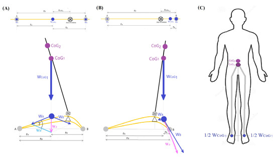
Figure 1.
Diagram of the ground load of the body weight (WCoG1) through the foot in the general body centre of gravity CoG1 inclination (including the support platform). (A) CoG1 deflection forward, (B) CoG1 deflection backwards. (C) Diagram of the human body with the general body centre of gravity (CoG1) and body weight symmetrically distributed on two feet. In a standing position on both feet, the load on each foot is equal to half the body weight value. A—front support point, B—rear support point, WA and WB—load on the front (A) and rear (B) support points, respectively, WJ—resultant of the forces of gravity WA and WB, WB’—vector parallel to WB with the same value, γ [°]—the angle between the vector WA and WB’ lying opposite the vector WJ, rCoG1—the arm of the gravity force of the general centre of gravity CoG1, rA—distance from point A to the projection of WCoG1 on the support platform, rB—distance from point B to the projection of WCoG1 on the support platform, rD—distance from point A to B, grey point with a cross – axis of rotation in the upper ankle joint.
Given the above parameters and using the principle of rotational moment balance for a two-supported beam (1) (2), the position of the general projection of the centre of gravity (CoG1) on the support platform was determined. With the known load of points, A and B (WA, WB) obtained by measuring the load on scales and the known distance between points A and B (rD), the distance from point A to the line of the general projection of the centre of gravity (rA) (3) and the distance from point B to the line of the general projection of the centre of gravity (rB) (4) were calculated (Figure 1A,B).
The position of the general projection of the centre of gravity CoG1 on the object’s support platform, indicating the location of the load on the support platform at this point (WCoG1), is located at a distance rA from point A and rB from point B. Determining the projection point of CoG1 on the support platform allows for plotting of two components of the foot load WA and WB, and then their resultant WJ (5) (Figure 1A,B). The resultant WJ indicates the value and direction of the load on the support platform and is dependent on the degree of the object’s inclination.
Given the values of vectors , the value of the gamma angle (γ) between vectors and was calculated based on the law of cosines (6) (Figure 1).
Since the model system has similar parameters to the model human, having determined the gamma angle (γ), the value of the resultant gravity force for the model human body was calculated (7).
For theoretical considerations, three-foot loading situations were distinguished, i.e., neutral situation, maximum body tilts forward or backwards (Figure 2A–C).
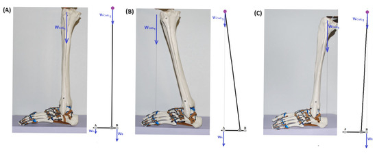
Figure 2.
Weight-bearing of the foot and position of the projection of the general centre of gravity (CoG1) on the support platform in the (A) neutral situation, (B) with maximum forward inclination of the CoG1, (C) with maximum backwards inclination of the CoG1. Point A—is the anterior support point of the foot, Point B—is the posterior support point of the foot, WCoG1—is total body weight including the weight of the support platform (foot), WA—is weight pressing the first metatarsal head to the ground, WB—weight pressing the calcaneal tuberosity to the ground.
2.3. Research Models—Flat Bar Model and Human Body
The human body in the model can be simplified into two elements, the support platform (i.e., the foot) and the rest of the body, which tilts at the upper ankle joint. This simplification allows for focusing on the relationship between the centre of gravity, the support platform (which bears the weight of the tilting flat bar), and the ground (which supports the weight of the entire model). It was not concerned with how the weight is distributed within the foot itself. Instead, it was focused solely on the loads at the extreme support points at specific tilt angles of the flat bar, while maintaining the system’s balance. By translating this to the human foot, it was aimed to capture the load on the head of the first metatarsal bone and the calcaneal tuberosity.
A model system was with a height of l1 = 2.06 m, which consisted of a metal flat bar (l2 = 2 m, width: 0.03 m) with a threaded rod with nuts imitating the weight of the human head placed at one end, and on the other side with a hinged platform imitating the footplate (lamina pedis). The height of the foot with the hinge is l3 = 0.06 m. The hinge in this system imitates the talus bone with a trochlea. The weight of the tilting part of the model (flat bar + rod with nuts) was 2.648 kg, and the entire system, together with the platform imitating the foot, was 2.972 kg. The centre of gravity for the tilted part of the model (CoG2) (without the support platform) is located at a height of 1.1 m (h2) from the axis of rotation, and 1.16 m from the ground (1.1 + height of the platform with a hinge of 0.06 m) (hCoG2). On the other hand, the general centre of gravity for the entire system (CoG1) together with the platform and hinge is 0.01 m lower, i.e., at a height of 1.15 m (hCoG1) measured from the ground, and measured from the axis of rotation at a height of 1.09 m (h1). The line indicating the projection of the centre of gravity on the support platform was obtained by mounting a cable with a weight at the centre of gravity point of CoG2. The hinge connecting the tilted part and the support platform imitates the upper ankle joint. Subsequent degrees of flat bar tilt relative to the support platform were stabilised by tightening the screw on the axis of rotation. Two scales (EKS002W, 1–5000 g, Digital scale, Esperanza-Extrim-Titanium, Ożarów Mazowiecki, Poland) were used to measure the ground load of the object (Figure 3A). The readings on the scales were checked based on standard weights of 0.5 kg and 1 kg. Before each weighing, the scales were tared. It was performed twenty-two repetitions of the gravity measurements at points A and B at each degree of flat bar inclination.
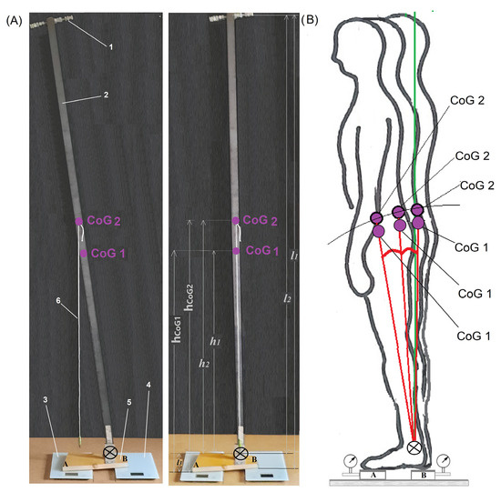
Figure 3.
Model for measuring the ground load through the extreme areas within the support platform of the model object. (A) Model of the foot and the tilted body placed on two scales, recording the forces exerted on the ground by the front and rear parts of the support platform. The loads were measured at different inclinations of the overall centre of gravity CoG1 from the neutral position to the maximum tilt, both forward and backwards. (B) Scheme of the tilt of the overall centre of gravity of the human body (CoG1). The ground load weight was recorded under the extreme points of support of the foot (points A and B) at different body tilts. CoG1—is the general centre of gravity of the model (with a support platform), CoG2—the centre of gravity of the tilting part of the object (without support platform), h1—distance from CoG1 to the axis of rotation, h2—distance from CoG2 to the axis of rotation, l1—object height measured from the ground, l2—object height measured from the axis of rotation, l3—support platform height measured from the ground to the axis of rotation, 1—a threaded rod with nuts imitating the head, 2—metal flat bar, 3 and 4—scales to measure the load at points A and B, 5—support platform, 6—rope indicating the projection of the centre of gravity, circle with a cross–axis of rotation.
In addition to the tests on the technical model (flat bar model), the ground loads at the level of the extreme support points of the human foot were also exam ined. The calculations were made for an example human with a total mass of 94.2 kG (CoG1), height of 1.82 m (and a distance from the axis of the upper ankle joint to the top of the head of 1.73 m), foot length of 0.23 m (rD), the distance from point A to the projection of the upper ankle joint axis (rA) equal to 0.13 m, and the distance from point B to the projection of the upper ankle joint axis (rB) equal to 0.045 m (Figure 3B). The CoG1 of the human body was located at a height of 1.064 m (hCoG1) from the plantar side of the feet, and at a height of 0.974 m (h1) from the axis of rotation. To calculate the CoG2 of the leaning body, the total weight of the human was reduced by the weight of the feet [19], which was finally 91.6 kG. The CoG2 of the leaning part of the human body was located at a height of 1.077 m (hCoG2) and a height of 0.987 m (h2) from the axis of rotation.
2.4. Statistical Analysis
Statistical analysis was performed to show differences between measurements at points A and B for different degrees of model and human body inclination. One-way ANOVA was used (the data meet assumptions of normality and equal variances). Then, a post hoc Tukey’s test was conducted to identify which groups differed. Calculations were performed in the R environment [20] using the stat library.
3. Results
3.1. Loading the Ground with the Weight of the Object Through the Support Platform from Maximum Forward Tilt to Maximum Backwards Tilt While Maintaining Balance
The ground loads were measured at the extreme support points A and B in seven situations, i.e., from the maximum forward inclination of the object’s centre of gravity (CoG1) through the neutral position to the maximum backwards inclination of the model object while maintaining balance (Table 1) (Figure 4C).

Table 1.
The mean with standard deviation ground load force through the foot at different positions of the CoG1 projection from maximum forward (100% of A point weight-bearing) inclination to maximum backwards (100% of B point weight-bearing) inclination on the support platform. A Point and B Point—the extreme points on the support platform, the lengths of the force vectors, and the angle (γ) of inclination of the flat bar. WA—component of the gravity force loading A Point, WB—component of the gravity force loading B Point and WJ—resultant of the gravity forces WA and WB, gamma (γ) [°]—the angle between the vector WA and WB’ lying opposite the vector WJ (Figure 1). The lengths of the vectors of the forces are WA, WB, and WJ expressed in [cm], and WA, WB, and WJ expressed in [kG]. * PBP—Passive balance Point, ** BBP—Basic Balance Point.
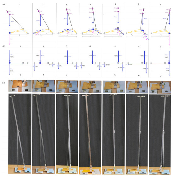
Figure 4.
Load on two extreme support points of the human foot (point A—head of the first metatarsal bone and point B—tuberosity of the calcaneal bone) from the maximum forward inclination of the general centre of gravity of the body (CoG1) to the maximum backwards inclination. (A) Projection of CoG1 in the sagittal plane onto the longitudinal arch of the foot, together with the distribution of load directions (WA and WB) and the resultant force (WJ) from full load on point A through subsequent stages of loading points A and B, up to full load on point B. (B) Percentage distribution of loads on points A and B in the foot reduced to a beam system supported at two points, i.e., at points A and B. (C) measurement results of the load on the front and rear parts of the support platform depending on the projection of the general centre of gravity of the flat bar model onto the support platform. CoG1—point of the general centre of gravity of the body, CoG2—point of the centre of gravity of the part of the body, which is tilting on the axis of rotation. WCoG1—whole body weight (including support platform).
The difference in load measurements at the extreme support points at different degrees of inclination was significantly different (p < 0.05). The load, the pressure of the object’s support points (WA, WB), was the greatest in the situation when the general projection of the centre of gravity (CoG1) fell on point A or point B. In each intermediate situation, the weight was distributed into two components, WA and WB > 0, with their resultant WJ, which is their vector sum (Figure 4(ABC1–ABC7)). WJ is the pressure force of the foot on the ground by the weight of the body at the point of projection of the general centre of gravity of the body onto the foot.
When the object is gradually tilted forward, rA shortens and rB lengthens, while when tilted backwards, rB shortens and rA lengthens, which affects the load distribution of point A and point B (Figure 4(B1–B7)). From the maximum load of point B to the maximum load of point A, the load distribution of points A and B can be calculated based on the principle of a beam supported at two points. Assuming that all the weight loading the foot is 100%, then depending on the degree of inclination of the centre of gravity (CoG1), the weight components (WA and WB) are distributed at points A and B to different degrees (Figure 4(B1–B7,C1–C7)).
Based on the measurement scheme used for the flat bar model, calculations for the human body were made (Table 2).
Table 2.
The values of gravity forces WA, WB and WJ for different degrees of body weight inclination (from maximum forward to maximum backwards) on the upper ankle joint of an example human. WJ was calculated based on the γ angle obtained for the flat bar model. * PBP—Passive Balance Point, ** BBP—Basic Balance Point.
Similarly, as for the flat bar model results, the difference in mean load measurements at the extreme support points at different degrees of inclination was significantly different (p < 0.05). Studies on the flat bar model and the human body, whose parameters differ, have shown a relationship between the degree of inclination of the general centre of gravity (CoG1) and the load on the extreme support points of the platform. Regardless of the type of object with the support platform, its weight and height, the ground load propagating through the support platform when the centre of gravity is projected onto the support platform so that the rA/rB ratio is the same causes the ratio of the loads on the extreme support points (WA/WB) are the same.
3.2. Loading the Ground with the Weight of the Human Body Through the Foot While Maintaining Balance
3.2.1. Loading the Ground in a Neutral Position
In a very simplified way, in the neutral position, the weight of the whole body (WCoG1) falls on the upper ankle joint axis, and from this is distributed between two main support points in the foot, i.e., the head of the first metatarsal bone (point A) on one side and the calcaneal tuberosity on the other (point B). Based on the principle of balancing the moments of forces in a loaded beam, the values of the load forces were determined at points A and B (WA and WB) (Figure 4A). For the model human foot, the distance from point A to the axis of the upper ankle joint (rA) is 0.13 m, and the distance from point B to the axis of the upper ankle joint (rB) is 0.045 m, WA and WB can be calculated from Formula (8).
The calculations show that in the neutral position, 74.28% (69.98 kg) of the human body weight is loaded by the calcaneal tuberosity (point B) and 25.72% (24.22 kg) of the weight is loaded by the forefoot (point A) (8) (Figure 4(A5,B5,C5)).
3.2.2. Load at Maximum Forward Tilt
At the maximum forward body tilt with maintaining balance, the entire body weight (WCoG1) is located at level I of the metatarsal head (point A), which is the most forward point of the support triangle. With the maximum load on point A, point B, i.e., the calcaneal tubercle, is simultaneously completely relieved. Knowing that at the maximum forward body tilt, rA is zero and rB is equal to rD and is 0.175 m in the case of a model human foot, then based on the rule of equality of torques, the loads on points A and B (WA and WB) are 94.2 kg (10) and 0 kg (9), respectively.
This means that in the position of maximum forward leaning of the body while maintaining balance, the forefoot is loaded 100% (Figure 4(A1,B1,C1)).
3.2.3. Load at Maximum Rearward Tilt
At the maximum backwards tilt of the body, while maintaining balance, the entire body weight (WCoG1) is at the level of the calcaneal tuberosity (point B), while the head of the first metatarsal bone (point A) is completely relieved. Knowing that at the maximum backward tilt of the body, rB is zero, and rA is equal to rD and is 0.175 m, then based on the rule of equality of torques in a beam supported at two points, WA and WB are 0 kG (11) and 94.2 kG (12), respectively. It follows that the entire weight of the tilted body loads the calcaneal tuberosity.
This means that in the position of the maximum backwards body leaning while maintaining balance, the hindfoot is loaded 100% (Figure 4(A7,B7,C7)).
4. Discussion
Scientific reports describe the results of experimental studies indicating a free upright position of a human with a slight forward tilt so that the overall projection of the centre of gravity falls in front of the axis of the upper ankle joint at the anterior edge of the lateral malleolus. Some researchers indicate a slightly larger forward tilt, due to which the load on both the hindfoot and forefoot is at a level of about 50% of the body weight [1,7,17]. Others indicate a tilt just at the anterior edge of the lateral malleolus, from where the load is distributed in 60% on the hindfoot to 40% on the forefoot [16]. Their descriptions of the biomechanics of the upper ankle joint and foot indicate that the projection of the centre of gravity in such a position falls on the axis of the upper ankle joint from where the weight is distributed into two vectors, one going towards the forefoot and the other towards the hindfoot [1,7,8,17], which is in contradiction with the load distribution based on the double-supported beam principle, based on which the foot loads should be considered.
Our experiments show that in the static upright position of a human, a neutral and passive state can be distinguished. Only in the neutral position does the general projection of the centre of gravity (CoG1) fall on the axis of the upper ankle joint at the Basic Balance Point [21], from where it is distributed bivectorally, i.e., towards the forefoot and hindfoot. This results in the forefoot being loaded with 25.72% and the hindfoot with 74.28% of the total body weight. There is no theoretical and practical possibility for the body weight distribution from the axis of the upper ankle joint to the forefoot and hindfoot in the proportions of 50%/50%, as some researchers claim [7] or 40%/60%, as others claim [16].
What some researchers observe in their experimental studies, reporting a load distribution of 40%/60% for the forefoot and hindfoot, respectively, results from the fact that a human most often has a passive upright position with a slight forward tilt in front of the axis of the upper ankle joint. This is the natural human standing upright position because the energy input is the smallest. In such a position, i.e., a slight tilt of the general body centre of gravity (CoG1), a small gravitational moment is generated, which is balanced by the moment of passive structures (ligamentous-capsular) of the upper ankle joint and the triceps calf [22,23,24]. In such a position, the projection of the general centre of gravity passes through the so-called Passive Balance Point (PBP). The load on the forefoot and hindfoot in the PBP position determined experimentally in our studies is approximately 40% forefoot and 60% hindfoot, respectively. There is no way that in such a position the projection of the centre of gravity passes through the upper ankle joint, as we have shown. In such a position, the vector load distribution (WA and WB) runs from the projection of the general centre of gravity (from the PBP point) on the support platform towards the forefoot and hindfoot, and their resultant force WJ indicates the direction and magnitude of the ground load through the foot.
The distribution of load across the foot has significant clinical implications. By identifying the correct loading patterns at the extreme support points and along the foot arch in a standing position, it is possible to develop diagnostic tools for detecting postural abnormalities. For instance, an excessive load on the forefoot may indicate a forward shift of the body’s centre of gravity, often observed in conditions such as pathological thoracic kyphosis (e.g., Bechterew’s disease), kyphoscoliosis, or flexion contractures of the hip joints. Conversely, an increased load on the hindfoot may suggest postural patterns such as flat back syndrome or lumbar hyperlordosis. In addition to aiding in diagnosis, such measurements can be used to monitor the progress of treatment during the implementation of a targeted rehabilitation protocol. In addition, surgical procedures aimed at increasing muscle moments [14], e.g., in weakened muscles or impaired muscle balance, will have to be revised. It should be taken into account that with maximum forward body tilt, CoG2 can be moved forward in front of the frontal support point of the foot while maintaining balance, while CoG2 cannot exceed it. This means that the gravitational arm for CoG2, and therefore the moment of gravity at maximum tilt, is greater than previously thought, which is why the counteracting moment of force of the triceps muscle also has a greater value [18]. The main limitation in the study of the ground load mediated by the support platform, which is the foot, is the difficulty in making precise, repeatable measurements using analogue models, and it is even more difficult to transfer such measurement methodology to the human body. The prepared analogue model (flat-bar model) simulating the tilt of the object on the axis of rotation located on the support platform, although it captures the principle of operation, gives only an approximation of the actual result. It focuses on static research. In the future, this type of research should be extended to dynamic research using sensors with a high level of precision, and then transferred to computer simulation conditions. In addition, a series of measurements should be performed on people to estimate the average values of CoG1 and CoG2 positions and gravitational and muscle torques (mainly the triceps calf muscle) for the human population in specific age, gender, or e.g., in different sports disciplines (developed upper body—higher centre of gravity, developed lower body—lower).
Such an approach will allow for more accurate calculations and transfer these observations to the human body with higher precision (the human general centre of gravity tilts on the axis of rotation of the upper ankle joint).
5. Conclusions
- -
- In the human upright standing position, two situations can be distinguished: one in which the projection of the general centre of gravity (CoG1) passes through the Basic Balance Point (BBP) and the other in which the CoG1 projection passes through the Passive Balance Point (PBP). The most energetically beneficial position is the PBP; however, in practice, there is an oscillation between PPB and BBP.
- -
- When the CoG1 projection falls in the Basic Balance Point (BBP), the forefoot is loaded by 26% and the hindfoot by 74%, while when the CoG1 projection falls in the Passive Balance Point (PBP), the forefoot is loaded by 40% and the hindfoot by 60%.
- -
- The more the CoG1 is tilted forward, the more the forefoot is loaded, and the hindfoot is relieved in proportion to the load on the forefoot.
- -
- If the ratio of the distance between the CoG1 projection on the support platform and points A and B (rA/rB) in the objects is the same, then the percentage load on the extreme points of the support platforms will be the same regardless of the characteristics of the objects tilting on the axis of rotation.
- -
- The direction and value of the load falling on the support platform are determined by the resultant force WJ, which is the vector sum of WA and WB. In the case of a human, this is a force flattening the arch of the foot.
- -
- Examination of the foot load at characteristic points, i.e., forefoot (100%/0%), rearfoot (0%/100%), midfoot (50%/50%), and Passive (40%/60%) and Basic Balance Point (24%/76%), can be used to determine whether we are dealing with correct or incorrect body posture. Any deviation from the foot load pattern at these points will indicate minor or major posture defects.
Author Contributions
Conceptualisation, J.M.D. and M.W.P.; methodology, J.M.D. and M.W.P.; formal analysis, J.M.D. and M.W.P.; investigation, J.M.D. and M.W.P.; resources, J.M.D. and M.W.P.; writing—original draft preparation, J.M.D. and M.W.P.; writing—review and editing, J.M.D. and M.W.P.; visualisation, J.M.D. and M.W.P.; supervision, J.M.D. and M.W.P. All authors have read and agreed to the published version of the manuscript.
Funding
This research received no external funding.
Institutional Review Board Statement
Not applicable.
Informed Consent Statement
Not applicable.
Data Availability Statement
The original contributions presented in this study are included in the article material. Further inquiries can be directed to the corresponding author.
Acknowledgments
We would like to express our gratitude to the head of the Department of Bioinformatics and Telemedicine at the Jagiellonian University Medical College, Andrzej A. Kononowicz, for his kindness and for allowing us to work on this project.
Conflicts of Interest
The authors declare no conflicts of interest.
References
- Kapandji, A. The Physiology of the Joints, 7th ed.; Handspring Publishing: London, UK, 2020. [Google Scholar]
- Silver, R.L.; De La Garza, J.; Rang, M. The Myth of Muscle Balance. J. Bone Jt. Surg.-Ser. B 1985, 67, 432–437. [Google Scholar] [CrossRef] [PubMed]
- Zhou, H.; Xu, D.; Quan, W.; Gao, Z.; Xiang, L.; Gu, Y. Are There Changes in the Foot Biomechanics during the before and after Fifth Metatarsal Fracture Running Stance Phase? iScience 2025, 28, 112432. [Google Scholar] [CrossRef] [PubMed]
- Bochenek, A.; Reicher, M. Anatomia Człowieka. Tom 1; Wydawnictwo Lekarskie PZWL: Warsaw, Poland, 2010; ISBN 978-83-200-4323-5. [Google Scholar]
- Vogl, A.; Mitchell, A.; Drake, R. Gray Anatomia. Podręcznik Dla Studentów Książka; Edra Urban & Partner: Wrocław, Poland, 2016. [Google Scholar]
- Liu, Y.; Fernandez, J. Randomized Controlled Trial of Gastrocnemius Muscle Analysis Using Surface Electromyography and Ultrasound in Different Striking Patterns of Young Women’s Barefoot Running. Phys. Act. Health 2024, 8, 223–233. [Google Scholar] [CrossRef]
- Mueller, M.J. The Ankle and Foot Complex. In Joint Structure and Function: A Comprehensive Analysis; Levangie, P.K., Cynthia, N.C., Eds.; McGraw Hill: New York, NY, USA, 2005; pp. 437–477. [Google Scholar]
- Schunke, M.; Schulte, E.; Schumacher, U. Prometeus Lern Atlas Der Anatomie Tom 1; Thieme: Stuttgart, Germany, 2006. [Google Scholar]
- Hoy, M.G.; Zajac, F.E.; Gordon, M.E. A Musculoskeletal Model of the Human Lower Extremity: The Effect of Muscle, Tendon, and Moment Arm on the Moment-Angle Relationship of Musculotendon Actuators at the Hip, Knee, and Ankle. J. Biomech. 1990, 23, 157–169. [Google Scholar] [CrossRef] [PubMed]
- Azar, F.M.; Beaty, J.H.; Canale, S.T. Campbell’s Operative Orthopaedics, 14th ed.; Elsevier: Amsterdam, The Netherlands, 2020; ISBN 9780323672191. [Google Scholar]
- Levine, D.; Richards, J.; Whittle, M.W. Whittle’s Gait Analysis, 6th ed.; Elsevier: Amsterdam, The Netherlands, 2022; ISBN 9780702084973. [Google Scholar]
- Xu, D.; Zhou, H.; Quan, W.; Ma, X.; Chon, T.E.; Fernandez, J.; Gusztav, F.; Kovács, A.; Baker, J.S.; Gu, Y. New Insights Optimize Landing Strategies to Reduce Lower Limb Injury Risk. Cyborg Bionic Syst. 2024, 5, 0126. [Google Scholar] [CrossRef] [PubMed]
- Dygut, J.; Piwowar, M. The Real Rotational Capacity of the Human Joints—The Muscular and Gravitational Torques and the Foot as a Platform. Acta Bioeng. Biomech. 2024, 26, 111–121. [Google Scholar] [CrossRef] [PubMed]
- Dygut, J.; Piwowar, M. Torques in the Human Upper Ankle Joint Level and Their Importance in Conservative and Surgical Treatment. Sci. Rep. 2024, 14, 7525. [Google Scholar] [CrossRef] [PubMed]
- Wang, M.; Song, Y.; Zhao, X.; Wang, Y.; Zhang, M. Utilizing Anthropometric Measurements and 3D Scanning for Health Assessment in Clinical Practice. Phys. Act. Health 2024, 8, 182–196. [Google Scholar] [CrossRef]
- Nordin, M.; Frankel, H. Basic Biomechanics of the Musculoskeletal System; Lippincott Williams & Wilkins, Wolters Kluwer Buisness: Philadelphia, PA, USA, 2012. [Google Scholar]
- Morton, D.J. The Human Foot: Its Evolution, Physiology and Functional Disorders; Columbia University Press: New York, NY, USA, 1935. [Google Scholar]
- Dygut, J.; Piwowar, M. The Methods of Determining the Centre of Gravity of a Tilting Body on the Upper Ankle Joint and Weighing the Feet of a Living Human. Appl. Sci. 2025, 15, 6812. [Google Scholar] [CrossRef]
- Stanley Plagenhoef, F.G.E.; Abdelnour, T. Anatomical Data for Analyzing Human Motion. Res. Q. Exerc. Sport 1983, 54, 169–178. [Google Scholar] [CrossRef]
- R Core Team. R: A Language and Environment for Statistical Computing; R Foundation for Statistical Computing: Vienna, Austria, 2024. [Google Scholar]
- Hicks, J.H. The Three Weight-Bearing Mechanisms of the Foot. In Biomechanical Studies of the Musculo-Skeletal System; Charles C Thomas Publisher: Springfield, IL, USA, 1962. [Google Scholar]
- Walsh, E.G. Muscles, Masses and Motion: The Physiology of Normality, Hypotonicity, Spasticity and Rigidity; Cambridge University Press: Cambridge, UK, 1992. [Google Scholar]
- Simons, D.G.; Mense, S. Understanding and Measurement of Muscle Tone as Related to Clinical Muscle Pain. Pain 1998, 75, 1–17. [Google Scholar] [CrossRef] [PubMed]
- Loram, I.D.; Maganaris, C.N.; Lakie, M. The Passive, Human Calf Muscles in Relation to Standing: The Short Range Stiffness Lies in the Contractile Component. J. Physiol. 2007, 584, 677–692. [Google Scholar] [CrossRef] [PubMed]
Disclaimer/Publisher’s Note: The statements, opinions and data contained in all publications are solely those of the individual author(s) and contributor(s) and not of MDPI and/or the editor(s). MDPI and/or the editor(s) disclaim responsibility for any injury to people or property resulting from any ideas, methods, instructions or products referred to in the content. |
© 2025 by the authors. Licensee MDPI, Basel, Switzerland. This article is an open access article distributed under the terms and conditions of the Creative Commons Attribution (CC BY) license (https://creativecommons.org/licenses/by/4.0/).