
Study on the Evolution Characteristics of Surrounding Rock and Differentiated Support Design of Dynamic Pressure Roadway with Double-Roadway Arrangement


Abstract
1. Introduction
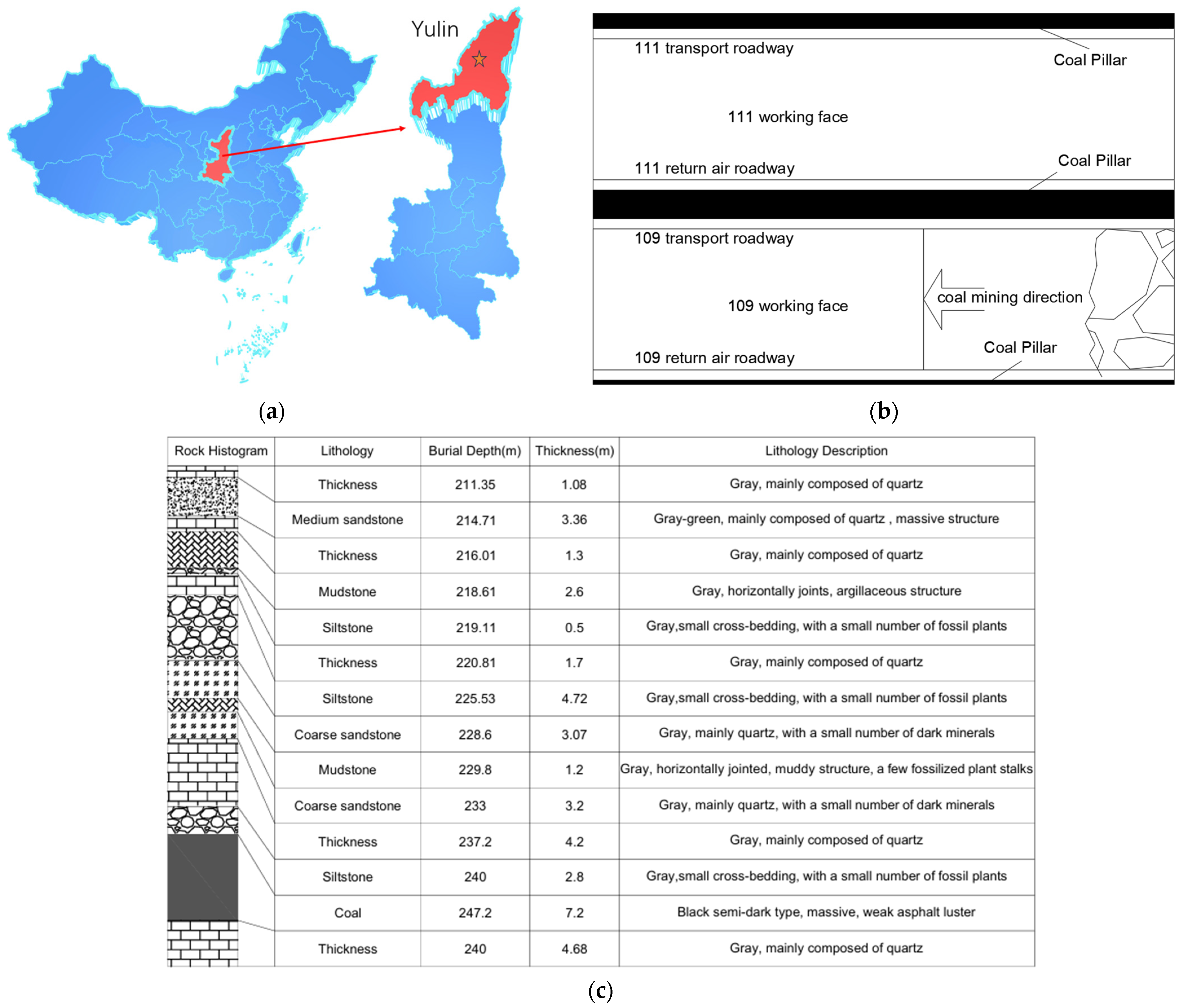
2. Project Overview
Geological Conditions
3. Size Optimization of Coal Pillar in Double-Roadway Excavation
3.1. Theoretical Calculation of Coal Pillar Width
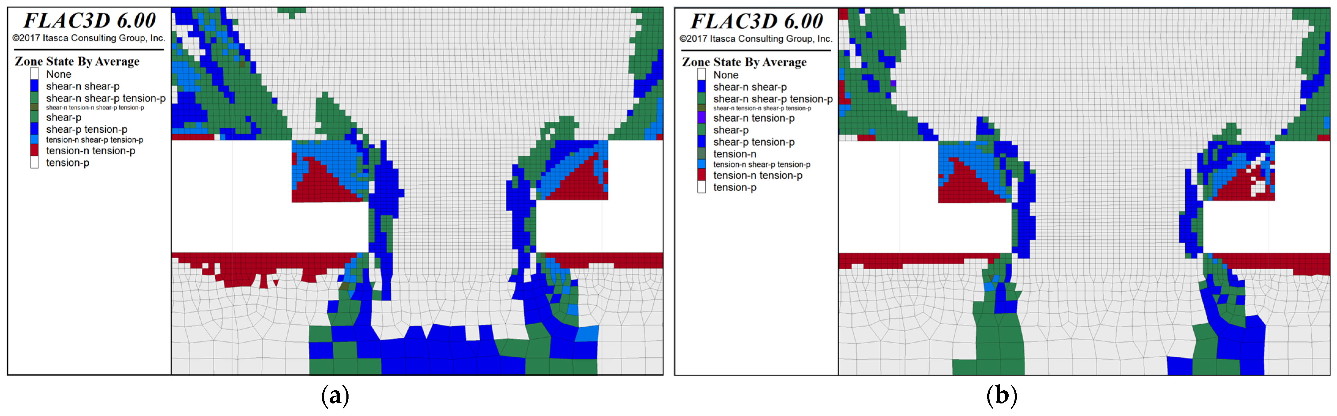
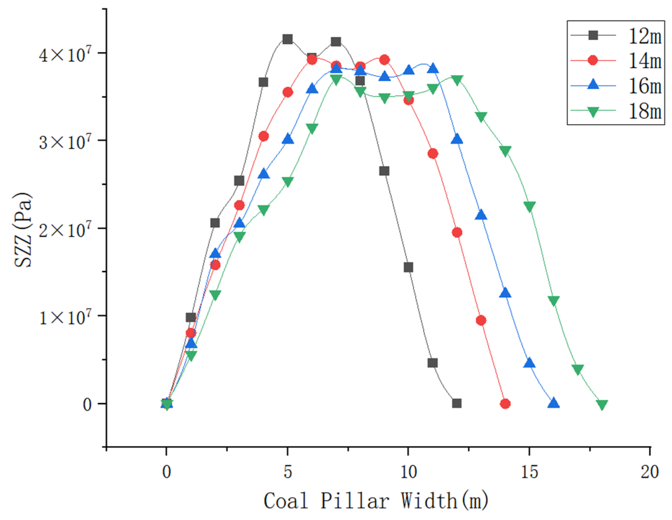
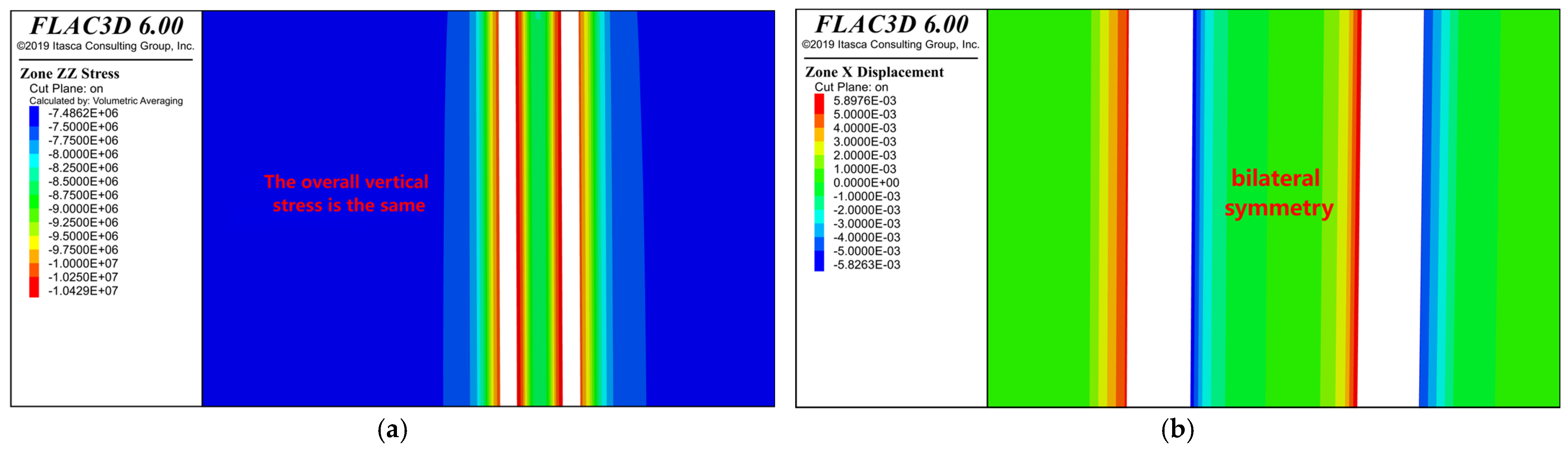
3.2. Coal Pillar Optimization Design Simulation Calculation
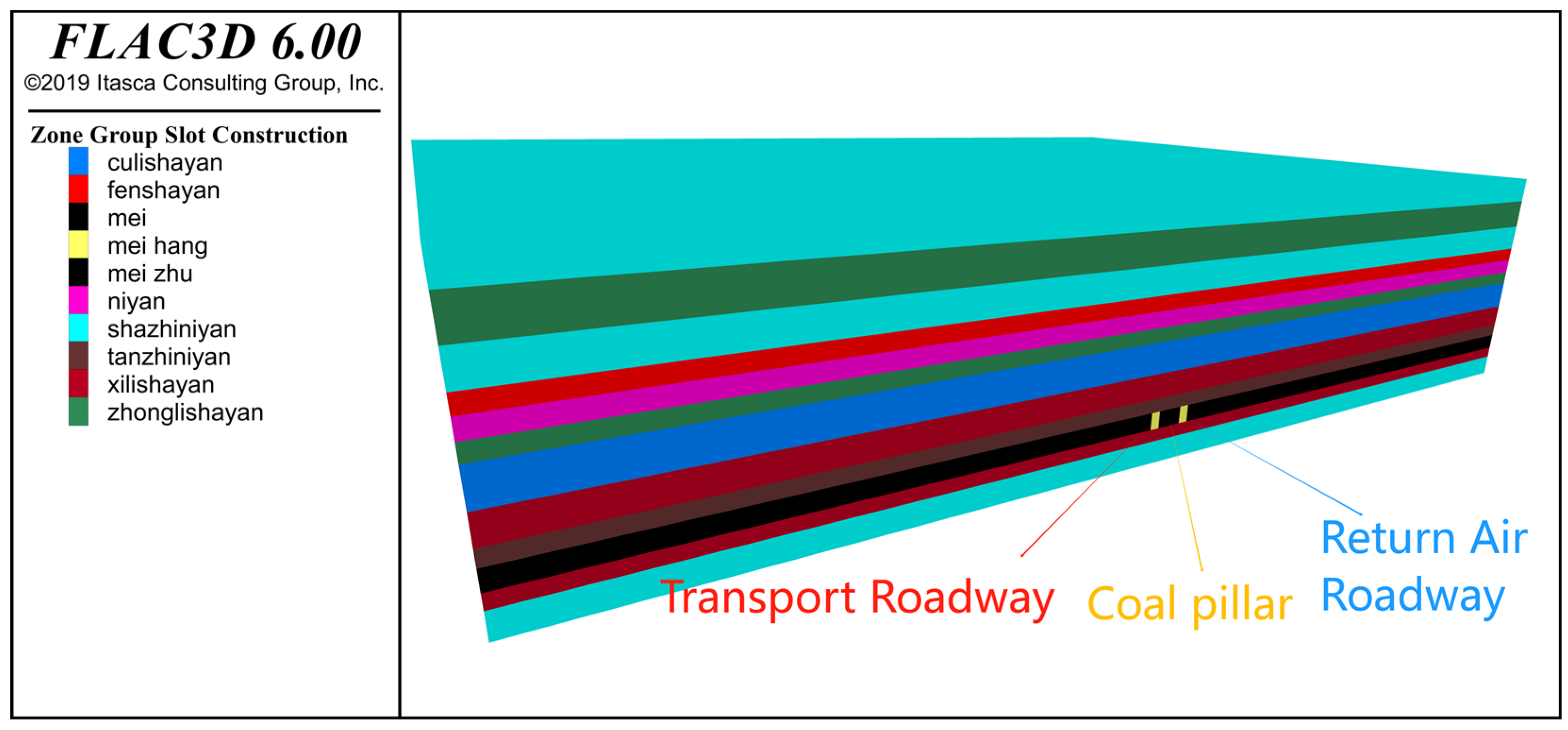
3.2.1. Model Establishment
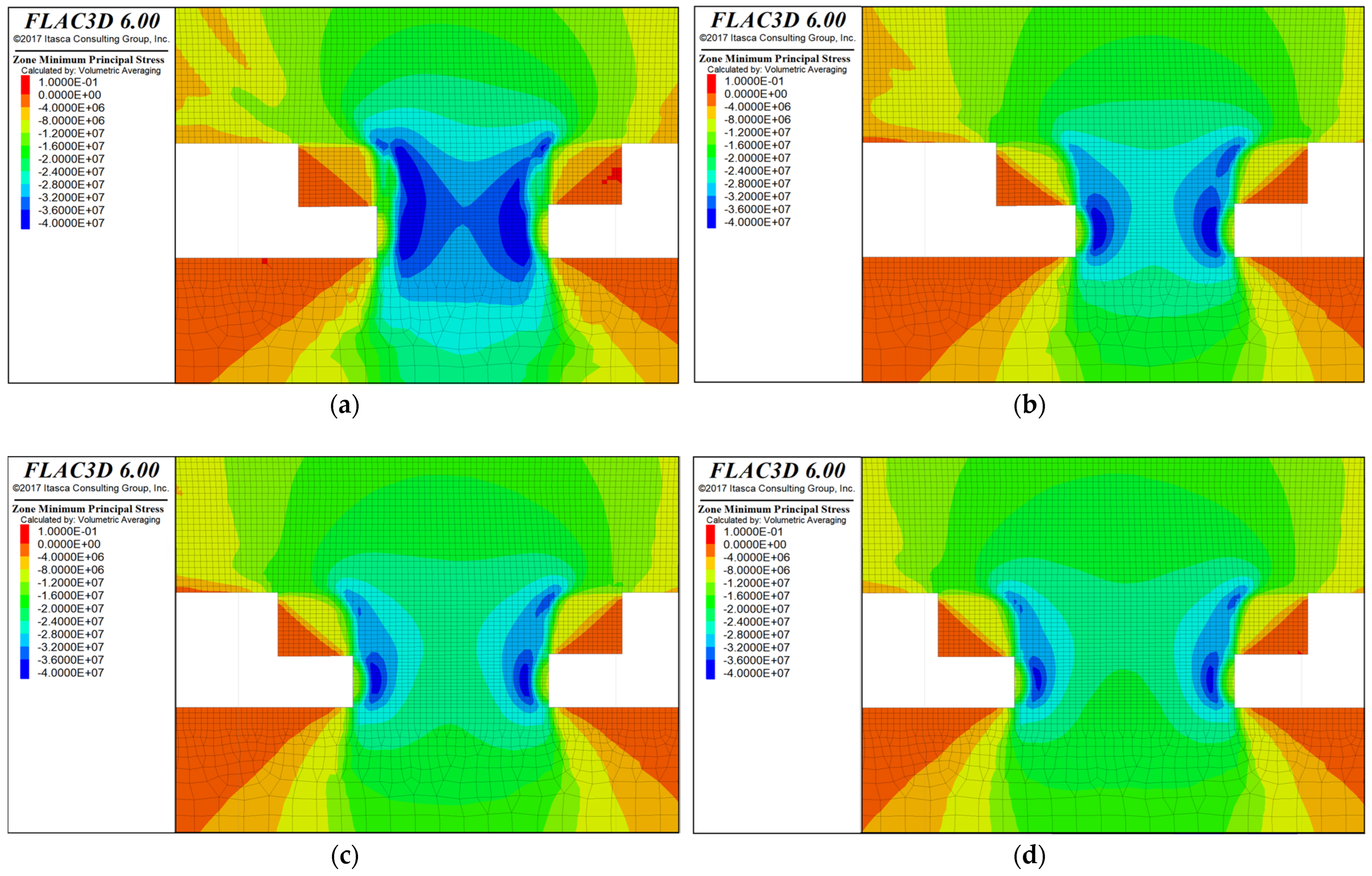
3.2.2. Computational Simulation
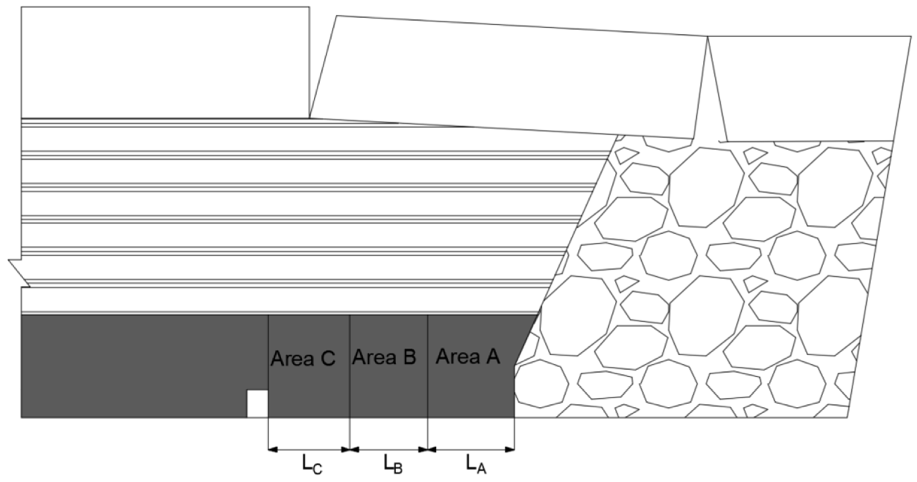
4. Double-Roadway Layout’s Surrounding Rock Movement Law
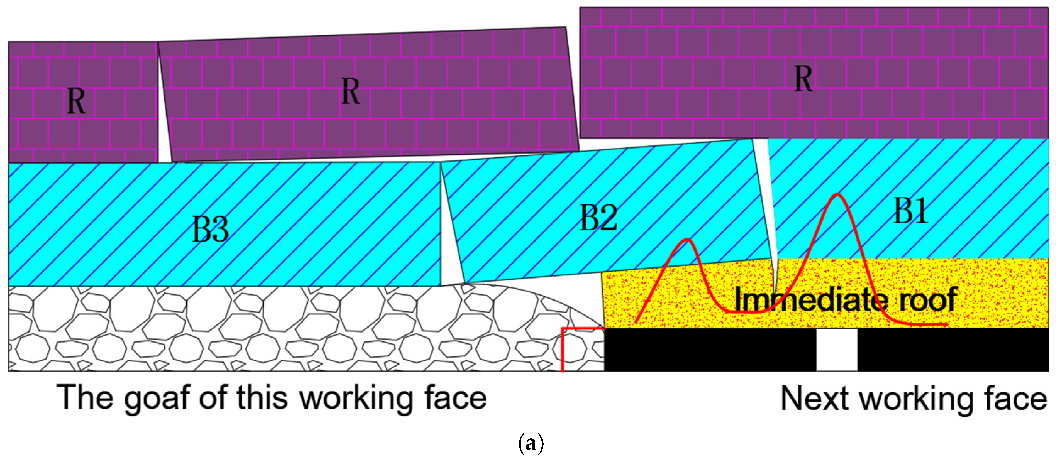
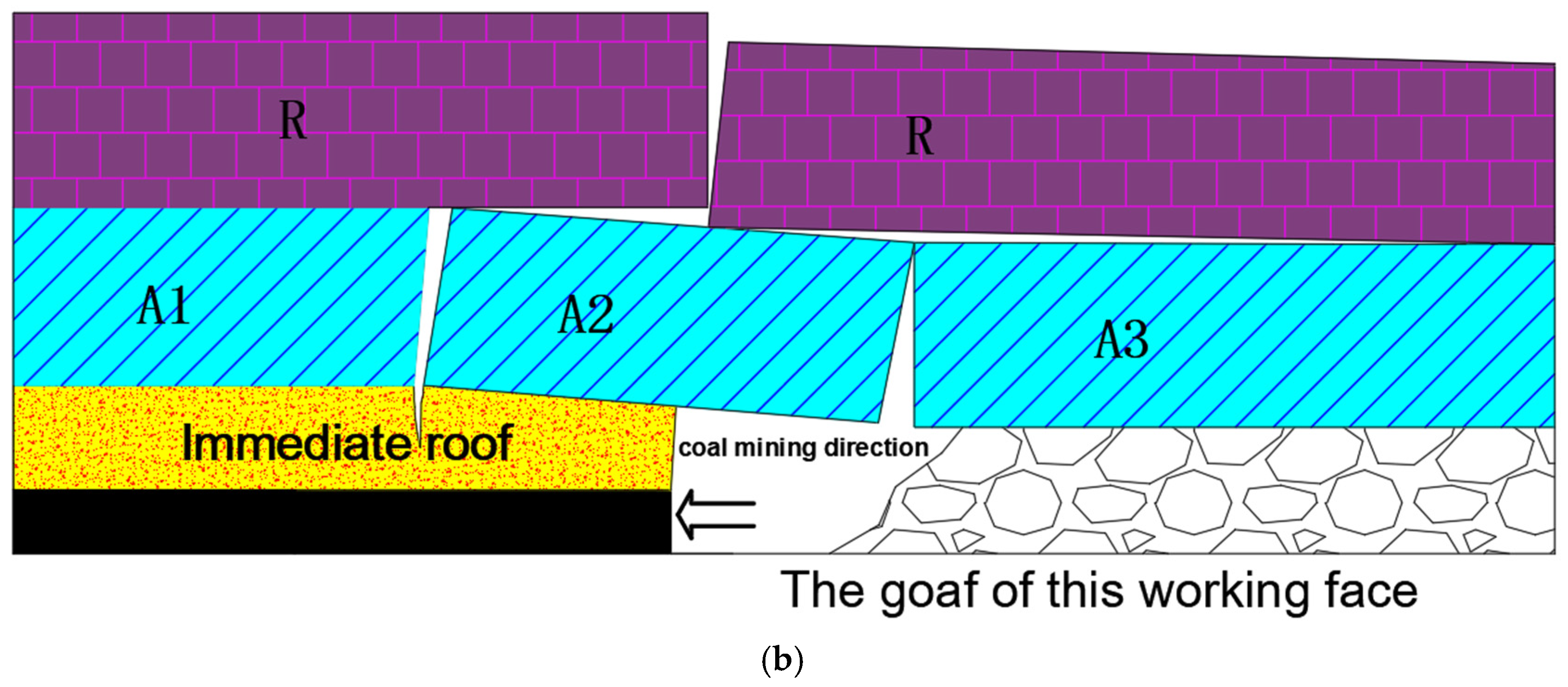
4.1. Characteristics of Rock Mass Movement
4.2. Characteristics of Differential Stress in Surrounding Rock
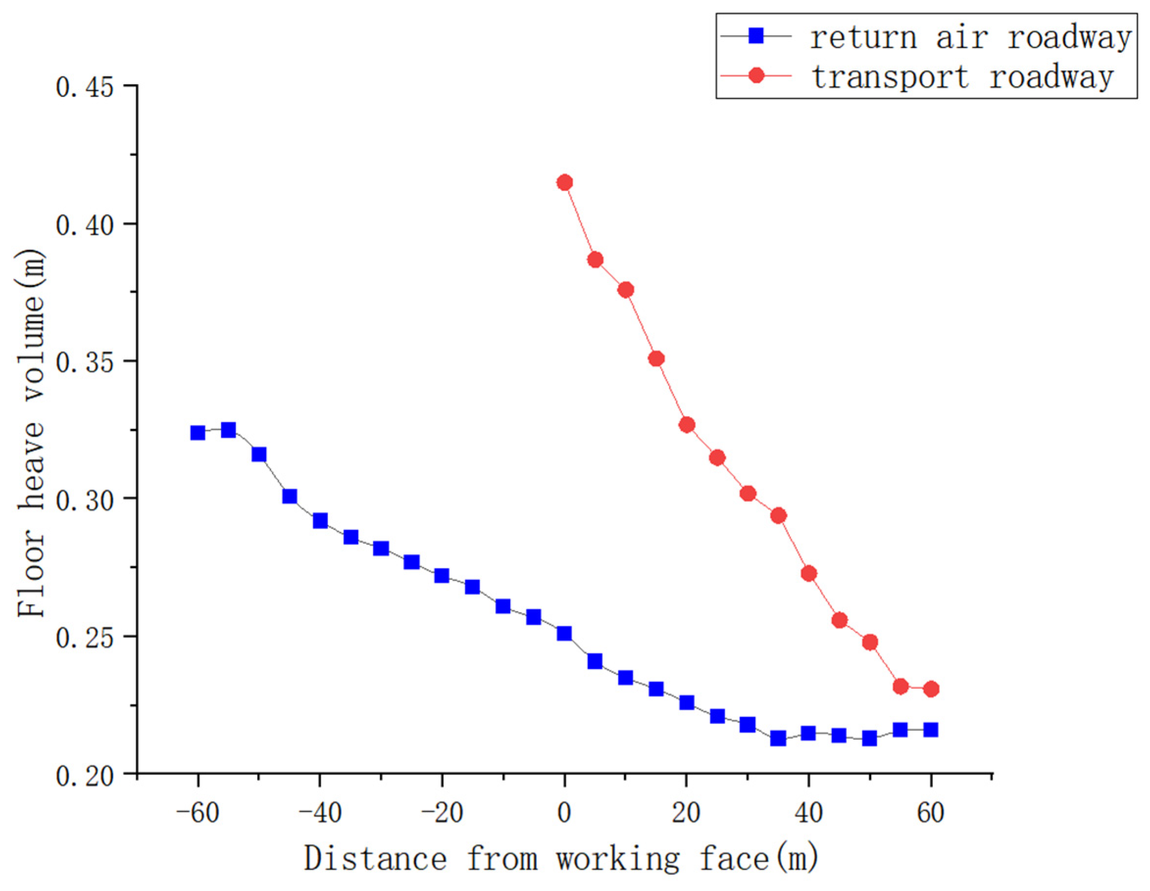
4.3. Surface Proximity Differential Characteristics
5. Double-Roadway Differential Support Design and Application
5.1. Principle of Differential Control
5.2. Differentiated Control Scheme
5.2.1. Differentiated Support Scheme for Class A Roadways
5.2.2. Differentiated Support Scheme for Class B Roadways
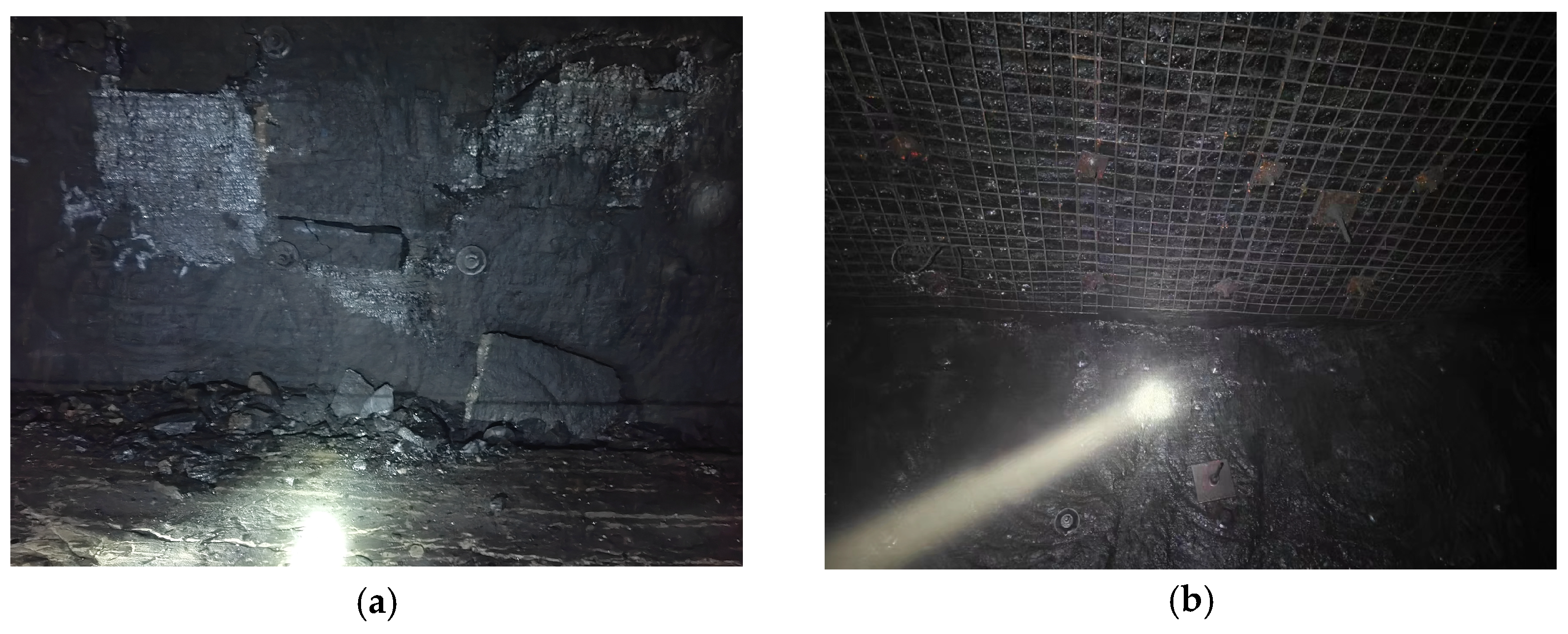
5.2.3. Actual Usage Effect of Class B Roadway Support
6. On-Site Data Monitoring
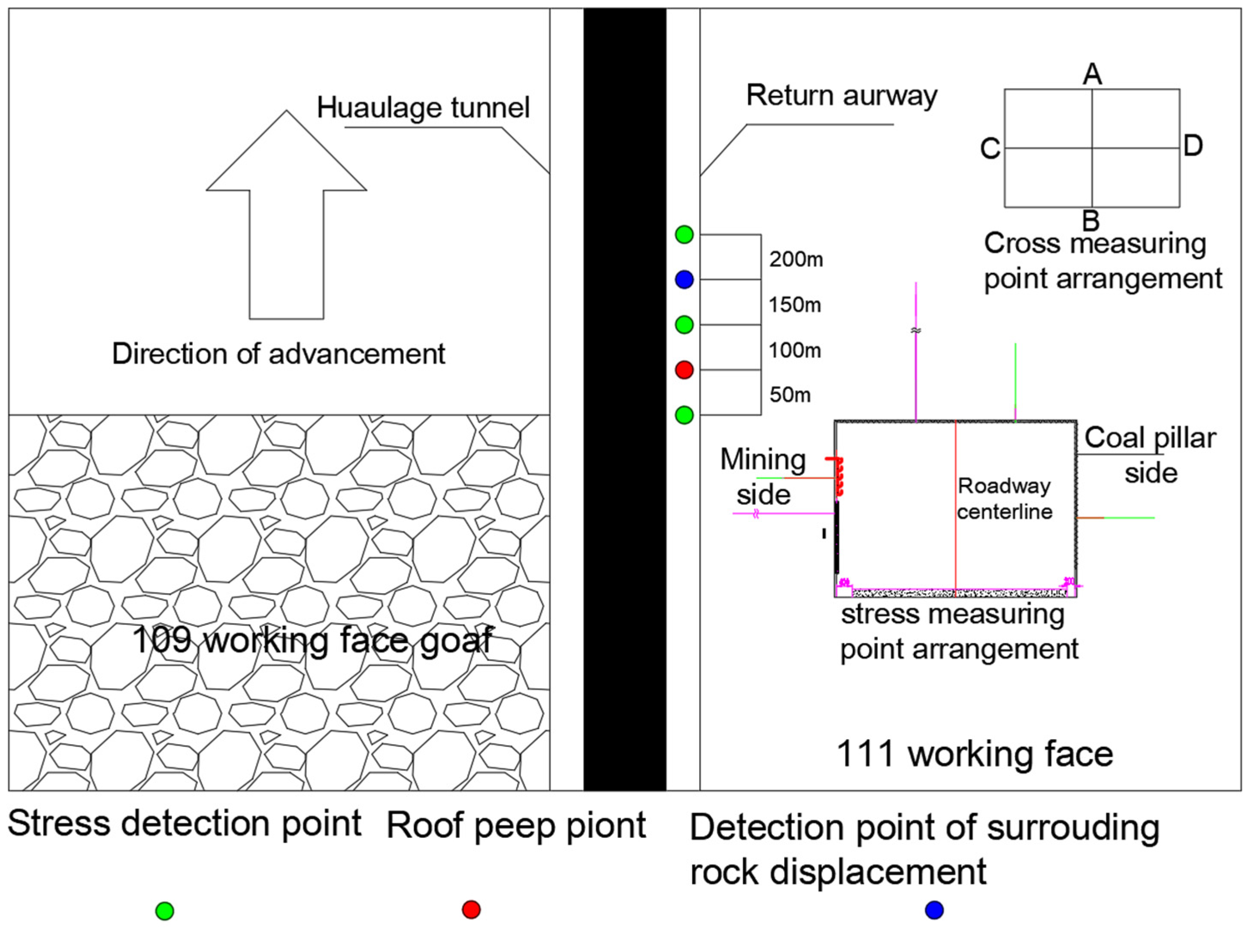
6.1. Measurement Point Arrangement
6.2. Analysis of Data Monitoring Results
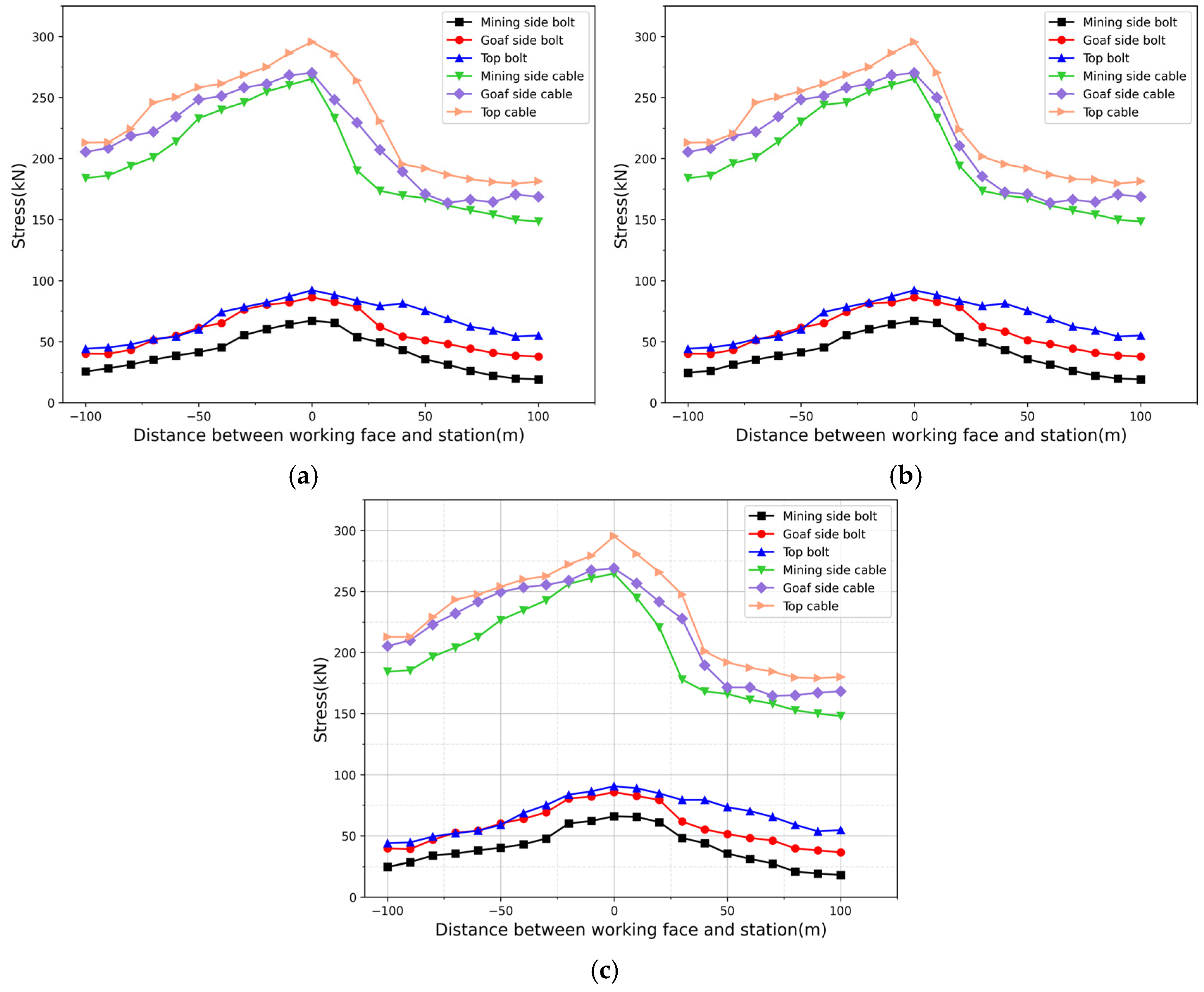
6.2.1. Monitoring of Anchor (Bolt) Forces in the Return Air Roadway
6.2.2. Monitoring of Surrounding Rock Convergence in Return Air Roadway
6.2.3. Advanced Working Face Roof Peeping
7. Conclusions
Author Contributions
Funding
Data Availability Statement
Acknowledgments
Conflicts of Interest
References
- Wu, L. Study on Mine-induced Stress of Reused Roadway in Longwall Mining with Two Gateroad Layout in Yangquan Mining Area; China Coal Research Institute: Beijing, China, 2018; Volume 12. [Google Scholar]
- Zhang, Z. The Study on Temporal and Spatial Evolution Characteristics of Surrounding Rock Stress Shell of Deep Roadway and Supporting Mechanism. Ph.D. Thesis, China University of Mining and Technology, Beijing, China, 2018. [Google Scholar]
- Kang, P.; Yan, L.; Guo, X.; Zhang, Z.; Gao, F. Characteristics of surrounding rock deformation and reinforcement technology of retained entry in working face with multi-entry layout. Chin. J. Rock Mech. Eng. 2012, 31, 2022–2036. [Google Scholar]
- Liang, Y.; Jin, J.; Zha, W.; Xu, T.; Cheng, W. Study on the evolution law of the ‘Butterfly-type’plastic zone in the surrounding rock of deep dynamic pressure roadway. Sci. Rep. 2025, 15, 2731. [Google Scholar]
- Fan, L.; Wang, W.; Yuan, C.; Ma, Y. Research on the differentiated support technology for roadways based on the mechanical response of the plastic zone. Energy Sci. Eng. 2024, 12, 670–683. [Google Scholar] [CrossRef]
- Zhu, L.; Liu, C.; Gu, W.; Yuan, C.; Wu, Y.; Liu, Z.; Song, T.; Sheng, F. Research on floor heave mechanisms and control technology for deep dynamic pressure roadways. Processes 2023, 11, 467. [Google Scholar] [CrossRef]
- Cui, J.; Wang, W.; Chao, Y. Application of stability analysis in surrounding rock control and support model of deep roadway. Int. J. Oil Gas Coal Technol. 2021, 29, 180–192. [Google Scholar] [CrossRef]
- Pang, S. Design and Practical of Equipment Remove Gateway of Fully Mechanized Coal Mining Working Face with Super Mining Height 8.2m. J. Min. Strat. Control Eng. 2018, 23, 45–49. [Google Scholar]
- Zhang, J.; Liu, L.; Yan, X.; Li, Y. Asymmetrical support technology for dynamic pressure roadway: A case study from Guotun coal mine in China. Geotech. Geol. Eng. 2019, 37, 823–832. [Google Scholar] [CrossRef]
- Wu, X.; Lai, X.; Guo, J.; Cui, F.; Wang, Z.; Xu, H. PSO-SVM prediction model of coal pillar width in fully mechanized mining face. J. Xi’an Univ. Sci. Technol. 2020, 40, 64–70. [Google Scholar]
- Cai, T.; Li, G.; Yang, Q.; Zhou, J. Study on the instability mechanism and control technology of narrow coal pillar in double-roadway layout of Changping mine. Sci. Rep. 2024, 14, 16676. [Google Scholar] [CrossRef]
- Liu, S.; Bai, J.; Wang, X.; Wang, G.; Wu, B.; Li, Y.; Zhao, J. Study on the stability of coal pillars under the disturbance of repeated mining in a double-roadway layout system. Front. Earth Sci. 2021, 9, 754747. [Google Scholar] [CrossRef]
- Landar, S.; Velychkovych, A.; Ropyak, L.; Andrusyak, A. A Method for Applying the Use of a Smart 4 Controller for the Assessment of Drill String Bottom-Part Vibrations and Shock Loads. Vibration 2024, 7, 802–828. [Google Scholar] [CrossRef]
- Peng, L.; Yue, N.; An, L.; Feng, Z.; Li, M. Study on support of retractable channel in fully-mechanized mining face with super large mining height. J. Coal Sci. Technol. 2022, 50, 204–210. [Google Scholar]
- Peng, L.; Liu, W.; Peng, C. Study on roof-cutting and support of a retreating roadway under the double influence of large mining heights. Appl. Sci. 2024, 14, 7946. [Google Scholar] [CrossRef]
- Wu, X.; Wang, S.; Gao, E.; Chang, L.; Ji, C.; Ma, S.; Li, T. Failure Mechanism and Stability Control of Surrounding Rock in Gentle Slope and Close Distance Mining Roadways. Eng. Fail. Anal. 2023, 152, 107489. [Google Scholar] [CrossRef]
- Guo, Z.; Li, W.; He, M.; Tang, J. Failure mechanisms and control strategies in dynamic pressure roadways of deep soft rock based on compensation theory. J. China Univ. Min. Technol. 2023, 52, 931–942. [Google Scholar]
- Cheng, J.; Wei, Z.; Bai, J. Study on floor heave control technology of deep tectonic stress water-rich soft rock roadway based on blasting pressure relief. Coal Sci. Technol. 2022, 50, 117–126. [Google Scholar]
- Peng, L.; Xu, X.; He, M. Numerical Simulation Study on Through-Anchor Cable Reinforcement Control of Inter-Roadway Coal Pillars in Double-Roadway Layouts. Sustainability 2025, 17, 2416. [Google Scholar] [CrossRef]
- Peng, L.; Gong, K.; He, M. Research on Width Optimization of Bearing Coal Pillar Between Roadways Under the Influence of Mining on Both Sides. Appl. Sci. 2025, 15, 314. [Google Scholar] [CrossRef]
- Guo, D.; Zhang, W.; Li, X.; Wang, H.; Zhao, Z.; Zhu, R. Comprehensive Pressure Relief Technology and Application for Small Coal Pillar Roadway Protection in Double Roadway Driving. J. Min. Saf. Eng. 2025, 42, 556–566. [Google Scholar]
- Liu, H.; Wu, X.; Gao, Z.; Hao, Z.; Zhao, X. Evolution Law and Stability Control of Plastic Zones in Retained Entries of Double Roadway Layout Working Faces. J. Min. Saf. Eng. 2017, 34, 689–697. [Google Scholar]
- Kumar, A.; Waclawik, P.; Singh, R.; Ram, S.; Korbel, J. Performance of a Coal Pillar at Deeper Cover: Field and Simulation Studies. Int. J. Rock Mech. Min. Sci. 2019, 113, 322–332. [Google Scholar] [CrossRef]
- Sun, N.; Sun, D. Study on Roof Caving Law and Coal Pillar Width in Large Mining Height Ultra-Long Working Faces. J. Energy Sci. Technol. 2023, 21, 22–26+30. [Google Scholar]
- Yu, Y.; Deng, K.Z.; Luo, Y.; Chen, S.E.; Zhuang, H.F. An Improved Method for Long-Term Stability Evaluation of Strip Mining and Pillar Design. Int. J. Rock Mech. Min. Sci. 2018, 107, 25–30. [Google Scholar] [CrossRef]
- Wang, Q.; Gao, H.; Jiang, B.; Li, S.; He, M.; Wang, D.; Lu, W.; Qin, Q.; Gao, S.; Yu, H. Research on Reasonable Coal Pillar Width for Roadways Driven Along Goaf in Deep Mines. Arab. J. Geosci. 2017, 10, 466. [Google Scholar] [CrossRef]
- Tao, Y.; Xiao, L.; Jia, J.; Jia, J.; Du, S. Study on the Mechanism of Floor Heave in Retained Roadways of Double Roadway Layout Working Faces and Reasonable Width of Coal Pillars for Roadway Protection. Coal Technol. 2023, 42, 77–81. [Google Scholar]
- Chen, S.; Zhu, W. Study on Double Roadway Layout Under Section Coal Pillars in Ultra-Close Upper Coal Seams of Huojitu Mine. J. Min. Saf. Eng. 2016, 33, 467–474. [Google Scholar]
- Yang, K.; Gou, P. Research on Differential Control of Surrounding Rock in Double Roadway Layouts Under High-Intensity Mining. J. Min. Saf. Eng. 2021, 38, 76–83. [Google Scholar]
- Hao, D.; Wu, Y.; Chen, H.; Chu, X.; Li, Y. Instability Mechanism and Control of Mining Roadways in Close Proximity to Thick Coal Seams Under Goaf. J. China Coal Soc. 2019, 44, 2682–2690. [Google Scholar]
- Xue, Y. Optimization of Small Coal Pillar Width and Control Measures in Gob-Side Entry Excavation of Thick Coal Seams. Sci. Rep. 2024, 14, 23304. [Google Scholar] [CrossRef]
- Gu, C.; Xu, Q.; Yang, H.; Fang, X.; Xue, G. Asymmetric Deformation Mechanism and Control of Roadways in Structurally Complex Areas. Geotech. Geol. Eng. 2021, 39, 145–155. [Google Scholar] [CrossRef]
- Li, C.; Huo, T.; Wu, Z.; Lv, K.; Zhang, B. Mechanism of Non-Uniform Severe Roof Deformation in Dynamic Pressure Roadways and Its Stability Control. J. Cent. South Univ. Sci. Technol. 2020, 51, 1317–1327. [Google Scholar]
- Yang, T.; Zhang, Y.; Zhang, J.; Lin, H.; Bao, R.; He, Y.; Yan, Y.; Luo, P.; Wu, H.; Sun, J.; et al. Study on the Stability and Reasonable Width of Coal Pillars in “Three Soft” Coal Seams Based on a Physical Similarity Simulation Experiment. Appl. Sci. 2024, 14, 6127. [Google Scholar] [CrossRef]
- Huang, W.; Zhao, T.; Jiang, D.; Guo, X.; Zheng, Y.; Wang, X. Arrangement of double entry driving with a narrow coal pillar in the middle and stability control technology of surrounding rock. Chin. J. Rock Mech. Eng. 2023, 42, 617–629. [Google Scholar]
- Niu, M.; Li, Q.; Liu, J.; Qian, D.; Wang, J.; Cao, Y.; Ma, K.; Wu, J. Research on Reasonable Width of Coal Pillars between Roadways for Double-roadway Tunneling in Thick Coal Seams with Shallow Buried Thin Bedrock in Zhuanlongwan Coal Mine. Coal Technol. 2024, 43, 25–28. [Google Scholar]
- Du, B.; Liu, C.; Yang, J.; Wu, F. Abutment pressure distribution pattern and size optimization of coal pillar under repeated mining: A case study. Arab. J. Geosci. 2020, 13, 1261. [Google Scholar] [CrossRef]
- Zhang, W.; Wang, X.; Xing, M.; Zhang, B. Theoretical and experimental study on the mechanical measurement of rock tensile fracture by ring radial compression. Géotechnique, 2024; ahead of print. [Google Scholar]
- Zhang, H.; Li, Y.; Wang, X.; Yu, S.; Wang, Y. Study on Stability Control Mechanism of Deep Soft Rock Roadway and Active Support Technology of Bolt-Grouting Flexible Bolt. Minerals 2023, 13, 409. [Google Scholar] [CrossRef]
- Hao, Y.; Li, M.; Wang, W.; Zhang, Z.; Li, Z. Study on the Stress Distribution and Stability Control of Surrounding Rock of Reserved Roadway with Hard Roof. Sustainability 2023, 15, 14111. [Google Scholar] [CrossRef]
- Ma, Q.; Zhang, Y.; Li, Z.; Zheng, Y.; Song, G.; Hu, L. The Optimized Roadway Layouts and Surrounding Rock Control Technology of the Fully Mechanized Mining Surface with Large Mining Heights in High-Gas Mines. Processes 2022, 10, 2657. [Google Scholar] [CrossRef]


| Lithology | Density/(kg/m3) | Elastic Modulus/(GPa) | Tensile Strength/(MPa) | Cohesion/(MPa) | Internal Friction Angle/(°) |
|---|---|---|---|---|---|
| Medium sandstone | 2653 | 12.5 | 4.6 | 2.5 | 31 |
| Mudstone | 2589 | 8.67 | 2.55 | 1.7 | 25 |
| Coarse sandstone | 2813 | 12.35 | 6.5 | 2.7 | 20 |
| Siltstone | 2680 | 16.5 | 6.97 | 1.3 | 21 |
| Coal | 1390 | 1.68 | 1.1 | 1.2 | 19 |
| Thickness | 2531 | 14.6 | 6.58 | 2.0 | 32 |
Disclaimer/Publisher’s Note: The statements, opinions and data contained in all publications are solely those of the individual author(s) and contributor(s) and not of MDPI and/or the editor(s). MDPI and/or the editor(s) disclaim responsibility for any injury to people or property resulting from any ideas, methods, instructions or products referred to in the content. |
© 2025 by the authors. Licensee MDPI, Basel, Switzerland. This article is an open access article distributed under the terms and conditions of the Creative Commons Attribution (CC BY) license (https://creativecommons.org/licenses/by/4.0/).
Share and Cite
Peng, L.; Wang, S.; Zhang, W.; Liu, W.; Hui, D. Study on the Evolution Characteristics of Surrounding Rock and Differentiated Support Design of Dynamic Pressure Roadway with Double-Roadway Arrangement. Appl. Sci. 2025, 15, 7315. https://doi.org/10.3390/app15137315
Peng L, Wang S, Zhang W, Liu W, Hui D. Study on the Evolution Characteristics of Surrounding Rock and Differentiated Support Design of Dynamic Pressure Roadway with Double-Roadway Arrangement. Applied Sciences. 2025; 15(13):7315. https://doi.org/10.3390/app15137315
Chicago/Turabian StylePeng, Linjun, Shixuan Wang, Wei Zhang, Weidong Liu, and Dazhi Hui. 2025. "Study on the Evolution Characteristics of Surrounding Rock and Differentiated Support Design of Dynamic Pressure Roadway with Double-Roadway Arrangement" Applied Sciences 15, no. 13: 7315. https://doi.org/10.3390/app15137315
APA StylePeng, L., Wang, S., Zhang, W., Liu, W., & Hui, D. (2025). Study on the Evolution Characteristics of Surrounding Rock and Differentiated Support Design of Dynamic Pressure Roadway with Double-Roadway Arrangement. Applied Sciences, 15(13), 7315. https://doi.org/10.3390/app15137315