Article

Research on the Implementation of a Heat Pump in a District Heating System Operating with Gas Boiler and CHP Unit

Faculty of Engineering, University of Rijeka, Vukovarska 58, 51000 Rijeka, Croatia
*
Author to whom correspondence should be addressed.
Appl. Sci. 2025, 15(13), 7280; https://doi.org/10.3390/app15137280
Submission received: 26 May 2025 / Revised: 13 June 2025 / Accepted: 19 June 2025 / Published: 27 June 2025

Abstract

Featured Application

This study provides a practical framework for retrofitting existing third-generation district heating (DH) systems currently reliant on gas-fired boilers and CHP units with medium-scale heat pumps. The findings support utility companies, energy planners, and municipal DH operators in designing optimised hybrid systems that reduce carbon emissions, improve energy efficiency, and adapt to fluctuating energy prices. The results can guide investment decisions and policy development for sustainable DH system upgrades, particularly in urban areas seeking to meet decarbonisation targets.

Abstract

Given the widespread use of gas-fired boilers and combined heat and power (CHP) units in existing district heating (DH) systems, this study investigates the integration of medium-scale heat pumps (HPs) into such configurations. Fifteen DH system variants were analysed, differing in installed HP capacity, operational strategies, and the synchronisation of heat and electricity production with thermal demand. A dynamic simulation model incorporating real-world equipment performance was developed to assess energy efficiency, environmental impact, and economic viability under three distinct energy price scenarios. The results demonstrate that an HP sized to 17% of the total heating capacity of the DH system achieves a 54% decrease in primary energy consumption and a 68% decrease in emissions compared to the base system. Larger HP capacities enhance environmental performance and increase the share of renewable energy but also entail higher investment. An economic analysis reveals that electricity-to-gas price ratios strongly influence the cost-effectiveness of HP integration. Under favourable electricity pricing conditions, systems with HP operational priority achieve the lowest levelized cost of heating. The most economically viable configuration consists of 600 kW HP and achieves a payback period of 4.7 years. The findings highlight the potential for HPs to decarbonize DH systems while emphasising the importance of market conditions and system design in ensuring economic feasibility.

1. Introduction

District heating (DH) systems play a crucial role in the decarbonisation of the energy sector. The improvement of DH systems through the use of heat pumps (HP) and renewable energy sources (RES) can lead to improved air quality and reduced dependence on fossil fuel imports. It is expected that the demand for accelerated decarbonisation and electrification of the energy sector will lead to an increased use of HPs.
A comprehensive definition and classification of DH systems based on the technology used and the period of implementation can be found in the literature [1]. Existing DH systems that rely on fossil fuels need to be upgraded to fourth-generation DH systems, which are characterised by lower operating temperatures in the pipe network, enabling lower heat losses and higher efficiency of HP. Alarnaout et al. [2] conducted theoretical analysis on complete replacement of gas boilers with small-scale high-temperature HPs which operate with synthetic refrigerant R1234-ze. The assessment of six distinct scenarios indicated that replacement ensures environmental and economic benefits for residential-use scenarios. In an analysis on the transition from the third to the fourth generation of DH system, Požgaj et al. [3] concluded that it is feasible to replace gas-fired boilers with commercially available medium-scale HPs utilising natural refrigerants. Volkova [4] theoretically evaluated three heating scenarios for a newly developed urban area in Estonia and concluded that low-temperature DH systems with large-scale HPs exhibited the lowest primary energy consumption and energy costs compared to high-temperature gas-boiler-based DH system.
The integration of combined heat and power (CHP) units into DH systems represents a transformative approach to energy generation, offering substantial efficiency, economic, and environmental advantages over conventional gas-boiler-based systems. CHP is a well-established technology that simultaneously produces electricity and thermal energy using a range of technologies and fuel sources, most commonly natural gas or coal. The viability of the utilisation of CHP technology within existing DH systems has been a subject of investigation by numerous authors [2,5,6,7,8,9,10,11]. These studies examined whether retaining existing CHP systems or replacing them with RES-based alternatives would be more feasible. Olympios et al. [12] found that a centralised DH system with CHP units is more advantageous than heating by decentralised gas boilers in London. In a recent study, Yu et al. [6] found that DH systems employing gas boilers and CHP units sized for base load heating can be economically competitive compared to individual heating systems utilising HPs. Reiter et al. [7] determined that it is feasible to replace the outdated CHP unit with solar thermal collectors and absorption HPs in a large-scale DH system in Graz. Popovski et al. [8] analysed the decarbonisation of a large-scale coal-fired CHP-based DH system in Germany, highlighting solar energy, biomass, waste incineration, and large-scale HPs as promising technologies. Despite their environmental benefits, large HPs were found to be economically uncompetitive without regulatory changes, prompting recommendations to lower electricity prices for HP operations.
The implementation of HP units within CHP-based DH systems plays a significant role in stabilising the electricity market, while it can also enhance energy efficiency and reduce environmental impact [5,13,14]. It can also improve system flexibility and reduce operational costs. In circumstances where electricity from RES is abundant and electricity prices are low, the utilisation of HPs becomes a priority. Conversely, when electricity from RES is insufficient and electricity prices are high, CHP units can operate profitably, generating both electricity and heat. Several studies have examined the integration of HPs into existing CHP-based DH systems. Ommen et al. [15] analysed various configurations for integrating HPs into DH systems incorporating gas-fired CHP units. They found that supplying HP-generated heat directly to consumers is more suitable for decentralised systems, whereas connecting the HP to the return pipe upstream of the CHP unit is better aligned with centralised system configurations. Capone et al. [16] investigated the placement of a large-scale HP within a DH system and concluded that incorrect placement has the potential to negate the positive effects by up to 63%. Levihn [14] provided practical insights into the DH network in Stockholm, where high-temperature HPs have been integrated with CHP plants since the 1970s. The study highlights that the combination of large-scale HPs and CHP enables flexible heat production and optimisation based on electricity prices. Aste et al. [9] examined the use of wood-biomass-powered CHP units and geothermal HP with photovoltaic (PV) power plants to achieve carbon dioxide (CO2)-free heat and electricity production for a DH system near Milan, Italy. Barco-Burgos et al. [10] demonstrated that small-scale DH systems with CHP units offer greater potential for the integration of high-temperature HPs compared to medium- and large-scale systems. Their analysis of 12 different system configurations showed that the optimal integration method varies with system complexity, highlighting the need for configuration-specific research. Ommen et al. [11] performed an analysis on the implementation of booster HPs in ultra-low-temperature and low-temperature DH systems. The overall system performance improved when a central HP was utilised in the return flow of the DH system but also determined lower efficiency for the system when an HP was placed in parallel with a CHP plant. Helin et al. [17] indicated that large-scale HPs in CHP-based DH systems, utilised during periods of low electricity prices, are economically viable and contribute to the reduction of CO2 emissions. The implementation of such HPs has the potential to reduce operating costs by 8–12% compared to DH systems based on CHP units.
While the literature has explored the integration of large-scale HPs either as replacements for, or in combination with, boiler or CHP-based DH systems, the potential of medium-scale HPs within existing third-generation DH networks that already utilize CHP and boiler technologies remains largely unaddressed. The modelling of HPs in these analyses also varies significantly, ranging from theoretical process models to data-driven approaches, both of which may not accurately represent commercially available products. Notably, research tends to focus on the operation of either CHP or heat pumps in isolation, with limited attention given to their synchronised operation within DH systems. Consequently, there is a clear research gap regarding the implementation and coordinated operation of medium-scale HPs alongside CHP and boiler units in existing third-generation DH systems.
This paper makes several key contributions to the field of DH system optimisation and decarbonisation. Specifically, it addresses the integration of medium-scale HPs into third-generation DH systems that are already operated with CHP and boiler units. The main research question of this study is as follows: Is it viable to implement medium-sized HPs to cover a fraction of the heating load in the DH system? This study is based on a comprehensive dynamic simulation model of the DH system encompassing consumers, distribution, and production subsystems. Unlike many previous works that rely on theoretical or simplified representations, this analysis incorporates the operational characteristics of commercially available equipment, thus providing more realistic insights into system performance. The research investigates various sizes of implemented HPs and explores multiple operational strategies, including prioritisation of technology and synchronised operation of CHP and HPs, as well as the management of produced electricity. Furthermore, the study evaluates the economic feasibility of these configurations under different gas and electricity price scenarios, reflecting the real-world volatility of energy markets.

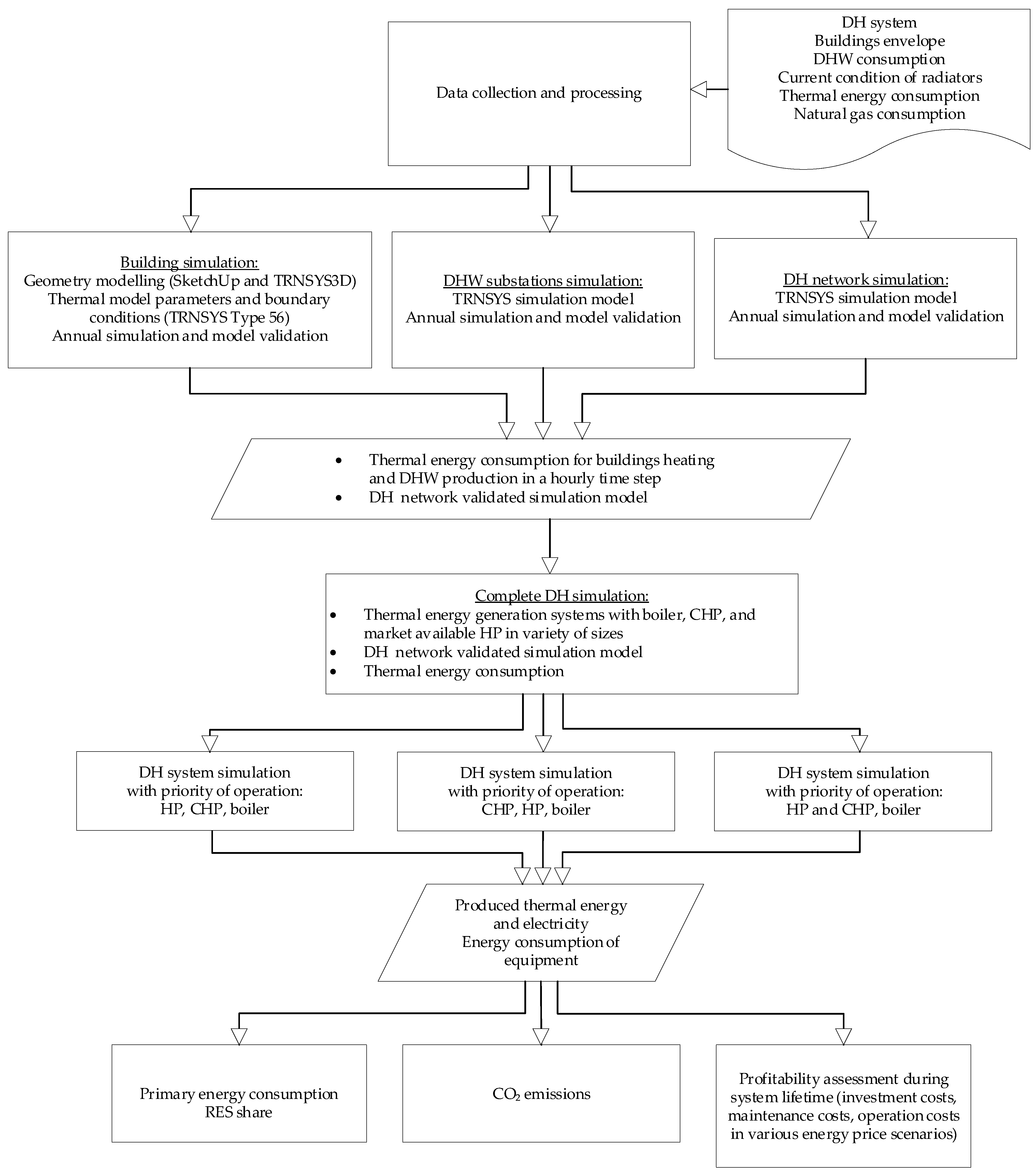
2. Materials and Methods

2.1. Methods

This research contributes to the ongoing discussion surrounding the integration of medium-scale HPs into third-generation DH systems that are already operated with CHP and boiler units. The research does this by systematically evaluating all the DH subsystems, with a focus on the thermal energy production subsystem under controlled operation conditions. This study evaluates the energy performance, costs, and CO2 emissions across a range of system configurations, operation regimes, and energy price scenarios. The primary flowchart of the model is presented in Figure 1.
To achieve a high degree of reliability, this study relies on the previous work of authors where a numerical model of a complete DH system was developed and validated [3]. The present study investigates the third-generation DH system in Croatia through a case study approach. The initial phase of the study entailed the aggregation and processing of all data pertinent to the DH system simulation. This encompassed the analysis of building design projects and the current state of the envelope and heating systems in buildings. Additionally, it involved the examination of DH data concerning equipment type and size, operational parameters, thermal energy utilisation in buildings, and fuel (natural gas) consumption.
Following the processing of the specified parameters, the TRNSYS 17 simulation environment was utilised to develop the dynamic simulation models. This decision was made due to the TRNSYS 17 environment’s proven capability to model complex interactions within energy systems [18]. For the sake of clarity, details on this process are briefly elaborated here, with further elaboration available in previous works by the authors. The design of simulation models for systems employing a natural gas boiler, CHP unit, and HP was informed by the thermal energy consumption of the DH system and the requisite thermal energy capacity in design conditions. The boiler and CHP unit were regarded as existing equipment within the system, while the CHP units were considered in a range of sizes. The operation of the CHP unit was simulated based on data provided by the manufacturer, with particular reference to capacities and efficiency at partial load. The operation of HPs was simulated based on manufacturer data. This process incorporated the consideration of efficiency at partial load, as well as variable heat sink and source temperatures. The system control was analysed within the context of three distinct operational strategies. The first operational strategy prioritised the operation of HP over CHP. The second operational strategy prioritised the operation of CHP over HP. The third operational strategy involved the simultaneous operation of CHP and HP, with adjustments made to meet the required thermal energy demands. In all three of the considered operational strategies, the priority assigned to the boiler operation was the lowest. Simulations were performed for a whole year operation of the DH system to include a realistic scenario comprising peak load periods during the winter period and those with lower load during the transitional and summer period. Outputs from simulations provided data on the produced and consumed energy by each generator in the system, enabling the calculation of key performance indicators, including primary energy consumption, the proportion of renewable energy within the system, and CO2 emissions. An economic analysis was conducted over the system’s lifecycle, considering three energy price scenarios to evaluate the investment’s profitability.

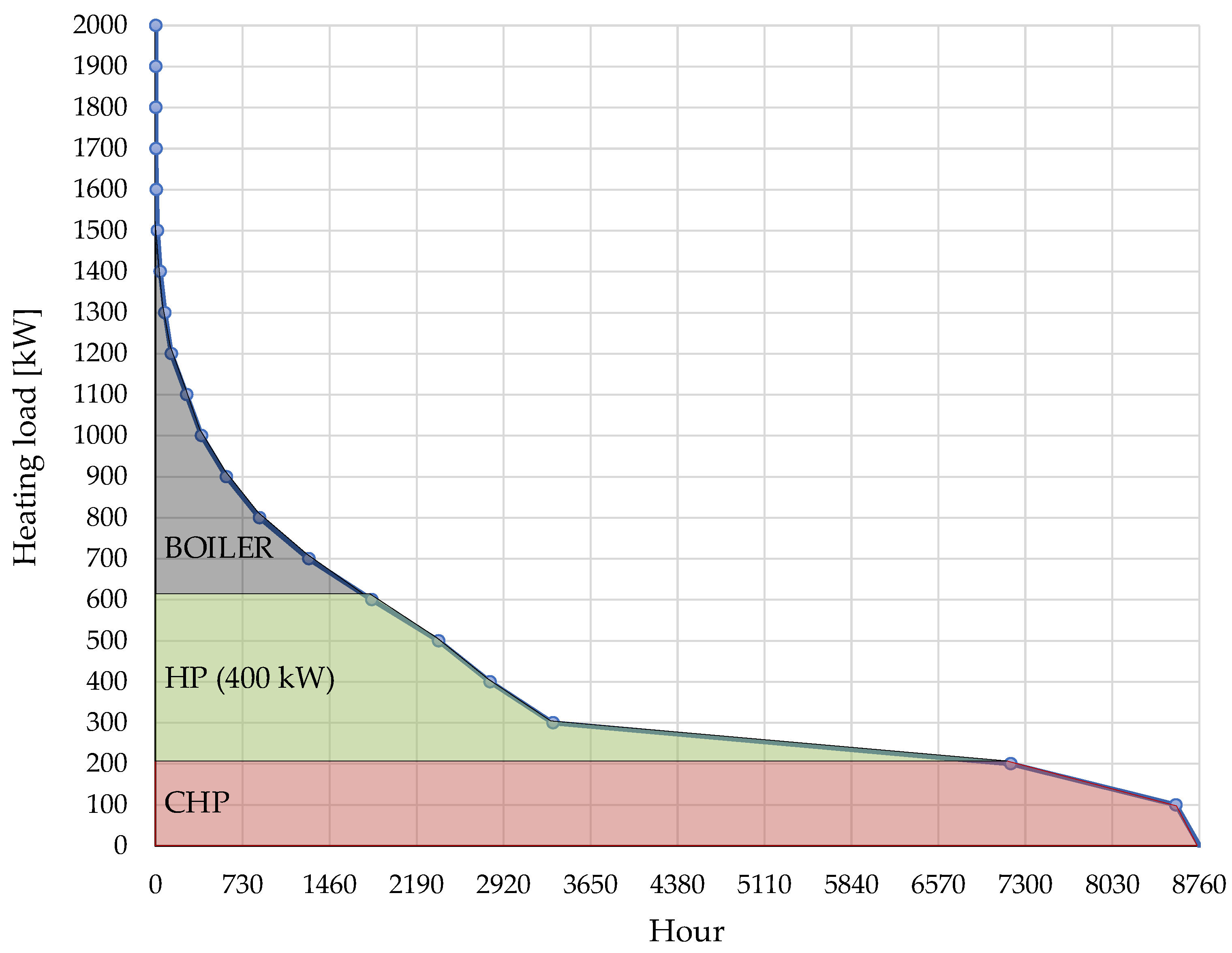
2.1.1. Control Logic for Technology Prioritisation in DH System Operation

DH systems often incorporate multiple heat generation units, such as CHP plants, HP, and boilers. In the simulations conducted, different operational strategies are analysed in which specific technologies are given priority, either operating individually (e.g., CHP or HP prioritised) or concurrently (e.g., CHP and HP operated in parallel).
The general control logic governing technology prioritisation is illustrated in Figure 2. This logic is applied at each simulation time step. At every time step, the required thermal capacity is calculated based on the system’s supply and return water temperatures. This demand is then compared to the maximum available capacity of the prioritised heat generator. If the required capacity is less than the maximum output of the prioritised unit, that unit is activated and operates at partial load, while all other generators remain off. Conversely, if the required capacity exceeds the prioritised unit’s maximum output, it is operated at full load, and the subsequent unit in the hierarchy is activated to supply the remaining demand, either at partial or full load, depending on the shortfall.

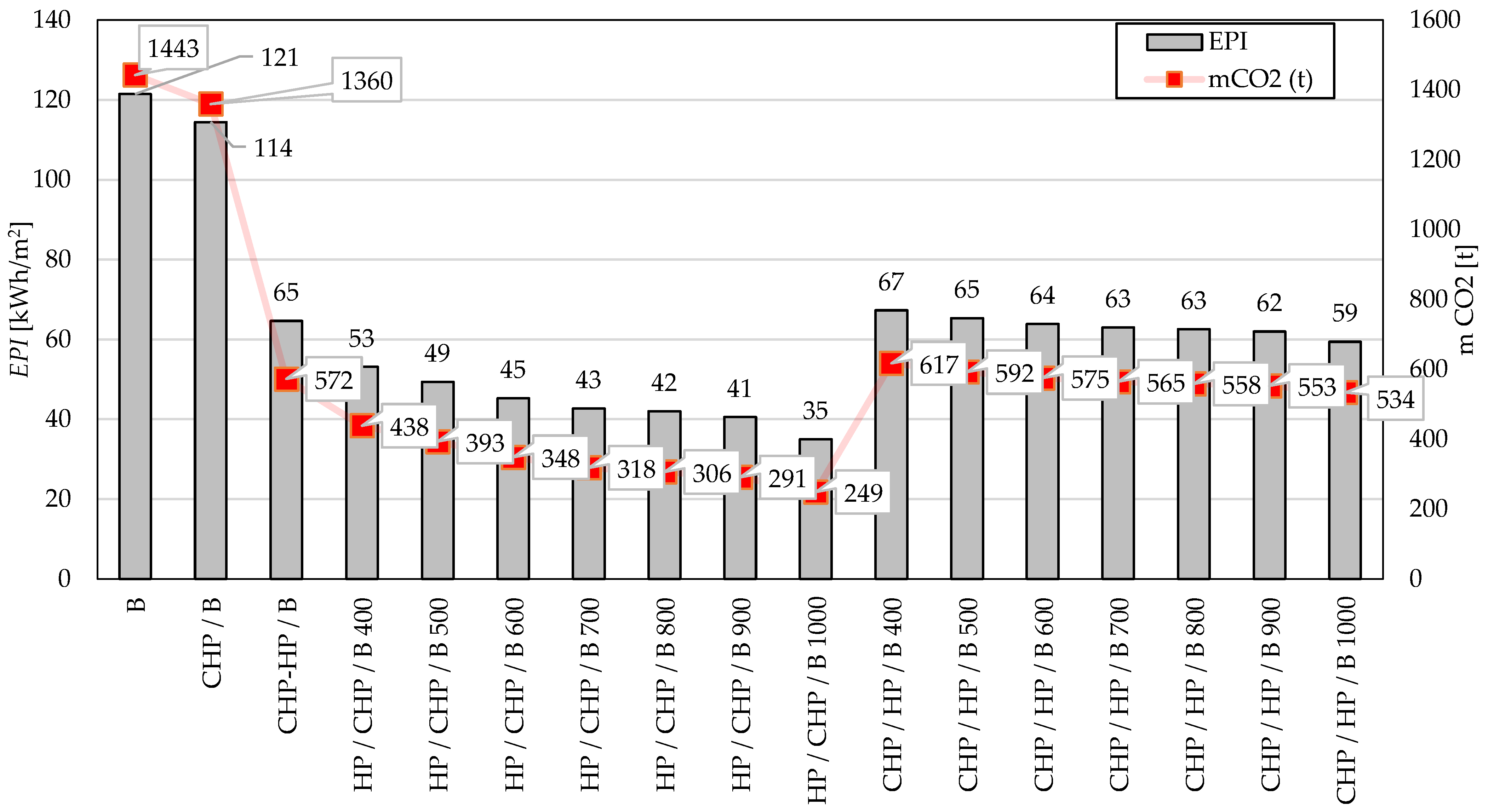
2.1.2. Calculation of Energy Performance Indicators

The results from dynamic simulations were used to calculate the system’s energy performance indicators. The scheme of the energy supply concept in the DH system is presented in Figure 3.
Energy flows are evaluated at each time step of the simulation. Energy consumption for the system operation is denoted as Econs, where Econs,g,B represents natural gas consumption in the boiler, Econs,g,CHP represents natural gas consumption in the CHP unit, while the electricity consumption from the HP unit is presented as Econs,ee,HP. The total produced thermal energy Eprod,t, which is distributed across the DH network, is calculated as the sum of thermal energy produced by each thermal energy generator in the system:
Eprod,t = SUM(Eprod,t,B + Eprod,t,CHP + Eprod,t,HP)
Natural gas is imported from the gas network; therefore, the imported energy to the system is calculated as follows:
Eimp,g = SUM(Econs,g,B + Econs,g,CHP)
The electricity produced by the CHP unit is denoted as Eprod,ee,CHP, the electricity which is consumed by HP is denoted as Econs,ee,HP, the electricity which is imported from the grid is expressed as Eimp,ee, while the electricity exported to the grid is Eexp,ee.
Concerning strategies for management of produced electricity, for the case when the electricity produced by CHP is used for HP operation, the calculation is as follows:
for Econs,ee,HP > Eprod,ee,CHP
Eimp,ee = SUM(Econs,ee,HPEprod,ee,CHP)
while the electricity which is exported to the grid is as follows:
for Econs,ee,HP < Eprod,ee,CHP
Eexp,ee = SUM(Eprod,ee,CHPEcons,ee,HP)
The exported and imported electricity for the case when the HP is operated by using electricity from the grid and the electricity produced by CHP unit is sold to the grid is calculated as follows:
Eimp,ee = SUM(Econs,ee,HP)
Eexp,ee = SUM(Eprod,ee,CHP)
The primary energy consumption EP is calculated as the product imported and the primary energy factor fimp,nren for each energy carrier. The calculation for electricity is performed in a way that imported energy is deducted by exported energy. Primary energy factors (fee,nren,i) depend on the share of renewable, non-renewable, and imported energy components. The primary energy consumption for electricity is calculated with a factor of 1.614, while the primary energy for natural gas is calculated with a factor of 1.095. These values are determined at the national level [19].
EP = SUM(Eimp,eeEexp,ee) ∙ fimp,nren,ee + SUM(Eimp,gfimp,nren,g)
The primary energy indicator EPI is defined as the ratio of total primary energy consumption to the total useful area of the buildings connected to DH system:
EPI = EP/A
The share of renewable energy RES is calculated using the following equation:
RES = SUM Econs,res/Eprod,t
In the Expression (9), Econs,res represents the renewable energy produced in the system. For heat generators powered entirely by natural gas, such as boilers and CHP units, Es,cons,res equals zero, and for systems using HP, it corresponds to the thermal energy derived from the source:
Econs,res = Eprod,t,HPEcons,ee,HP

2.1.3. Calculation of the CO2 Emissions

Emissions of CO2 (mCO2,i) for each energy carrier are calculated as follows:
mCO2,i = Es,imp,ifem,i
The specific CO2 emission for electricity is 0.2348 kg/kWh, whereas the specific emission for natural gas is 0.2202 kg/kWh. These values are defined at the national level [19].

2.1.4. Calculation of Costs
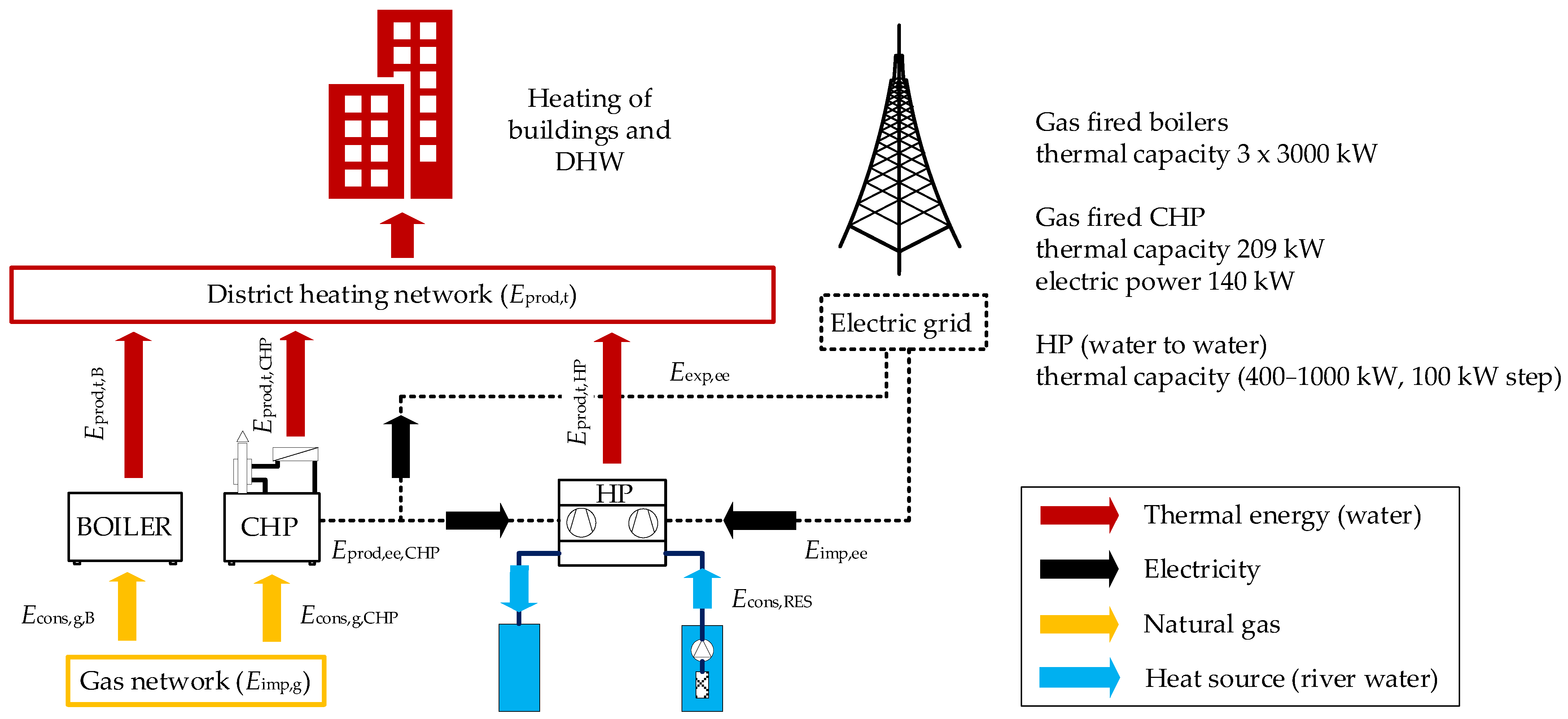
The total costs comprise investment costs for equipment, operating costs, and maintenance expenses. The present value of total costs is determined using the following equation:
Ct (τ) = CI + SUM [Ca,iRd − Vf,τ]
where τ represents the accounting period, CI is the initial investment cost, Ca is the annual operating cost, Rd is the discount factor for each year, and Vf,τ is the residual value at the end of the evaluation period. The calculation is repeated annually over the accounting period.
The discount factor Rd(p) is defined by the following:
Rd(p) = [1/(1 + r/100)] p
p represents the year, and r is the discount rate.
Levelized cost of heating CLH is calculated for all scenarios and system variants considered in this study. It is defined as the ratio of the total system costs to the total thermal energy produced over the evaluation period, as expressed by the following equation:
CLH = Ct (τ)/Eprod,t (τ)

2.2. Case Study

The research is conducted on the case study of one of the existing DH systems in Rijeka, Croatia. Constructed in the 1970s, the DH system services eight multi-story buildings and one primary school, covering a total heated area of 48,455 m2. TRNSYS Type 56 multi-zone thermal model [18] is used to perform simulations of buildings and determine the required energy for heating. The methodology for developing and validating consumer, distribution, and production models has been detailed in a prior study by the authors [3].
The design load for heating of buildings was determined through dynamic simulation within the TRNSYS interface, consistent with the HRN EN ISO 12831-1:2017 standard [20]. The calculated design heating capacity was 2195 kW.
The total number of apartments in the DH system is 601, and the calculated capacity for DHW heating is 569 kW. The simultaneity factor of the heat load for heating buildings is 0.8 according to standard DIN 4708-2 [21]. Network heat losses were determined by dynamic simulation using TRNSYS Type 951. The heat pipelines’ annual heat losses amounted to 167 kWh/m, with a peak hourly loss of 17.16 kW. Accordingly, the total heat capacity requirement in design conditions is 2342 kW. Characteristics of the DH system are outlined in Table 1.
The supply temperature in the DH network, under the assumption that all buildings undergo energetic renovation while retaining the current radiators, is 72 °C at an outdoor design temperature of −8 °C. During the heating season, the temperature of the supply pipe in the network varies in response to the external temperature, ranging from a maximum of 72 °C to a minimum of 65 °C. It does not fall below 65 °C due to demand for DHW in buildings.
In addition to the boiler and CHP-based systems, 15 variants of systems with implemented HP units were considered. These systems employ a gas-fired boiler, a CHP unit, and a water-to-water HP in different sizes. They are designed to meet the same heat load for space heating and DHW, maintaining a supply temperature within the DH network.

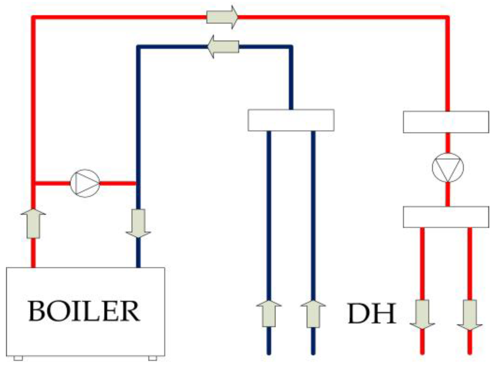
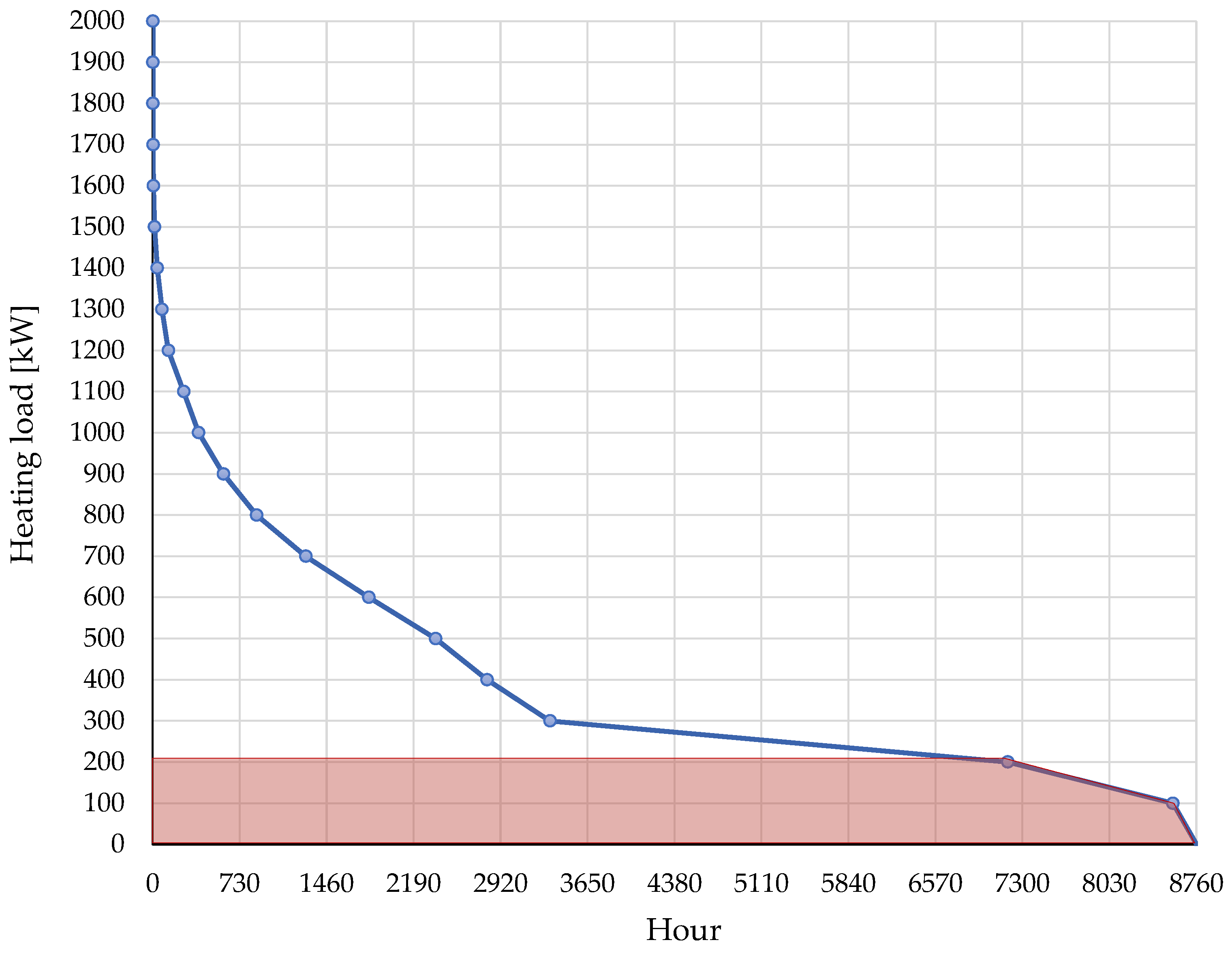
2.2.1. System with Gas-Fired Boiler

The gas-fired boiler system represents the original method of heat production established during the construction of the DH system. This system comprises three gas-fired boilers with a total heating capacity of 9 MW. The capacity is oversized, as it was based on the heating demand at the time of the system’s installation, when the connected buildings were not yet renovated. Additionally, a reserve capacity was included for potential system expansion. The dynamic simulations of the gas-fired boiler operation were conducted using Trnsys Type 751 [22]. Figure 4 presents a schematic of a third-generation DH system based exclusively on oversized gas-fired boilers. This configuration represents the legacy system used for thermal energy production before any modernisation involving CHP units or HPs. It serves as one of the baseline scenarios against which all proposed modernisation variants are evaluated in terms of performance and cost-effectiveness.

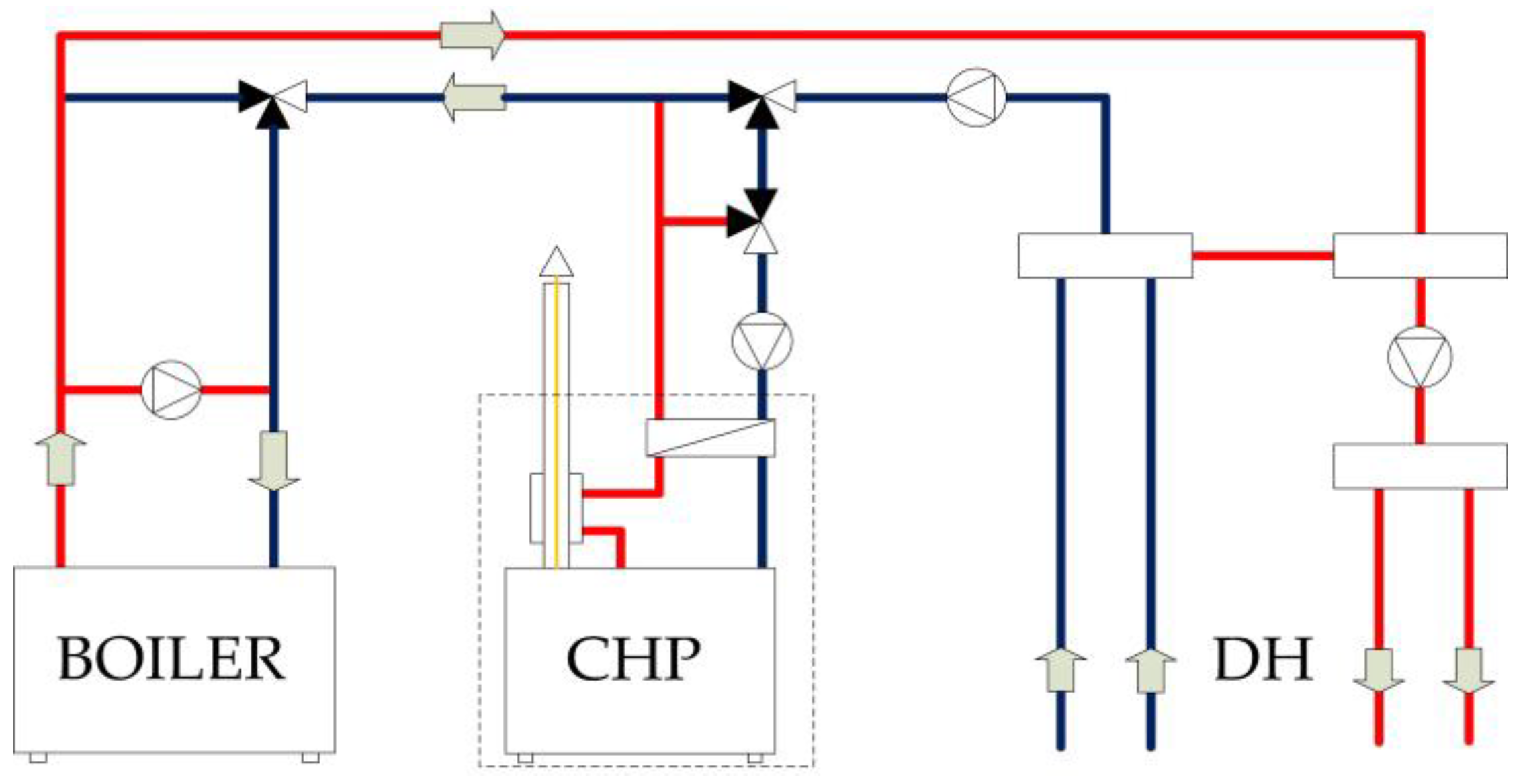
2.2.2. System with Gas-Fired Boiler and CHP Unit

The heat production system consists of a gas-fired boiler and a CHP unit powered by a gas engine, as shown in Figure 5.
The CHP unit is installed in the return line of the heating system, thereby ensuring priority in the production of thermal energy. The gas-fired boiler is activated when the CHP unit is unable to achieve the required water temperature. A comprehensive system simulation was performed to determine the heating energy required for space heating, DHW, and the heat losses in the distribution network during the year. The simulation results were integrated over an hourly time step to obtain the necessary thermal output. The data were then filtered based on the frequency of occurrence throughout the year and sorted from highest to lowest values.
The annual duration curve of the required heating capacity is illustrated in Figure 6. The area beneath this curve represents the total thermal energy required by the DH system. By the aforementioned figure and the established practice that the CHP device should achieve more than 5000 operating hours during the year, a CHP unit with a heating capacity of 209 kW was installed. This unit can operate at full load for 6685 h per year and even more if a partial load operation is introduced. The area of the corresponding rectangle illustrates the thermal energy produced by the CHP unit with a heating capacity of 209 kW.
The technical specifications of the CHP unit with a gas engine are provided in Table 2 [23]. The CHP unit was modelled using the Trnsys Type 211 component developed by the authors [24]. This black-box model incorporates manufacturer catalogue data and allows partial load operation at specified increments.

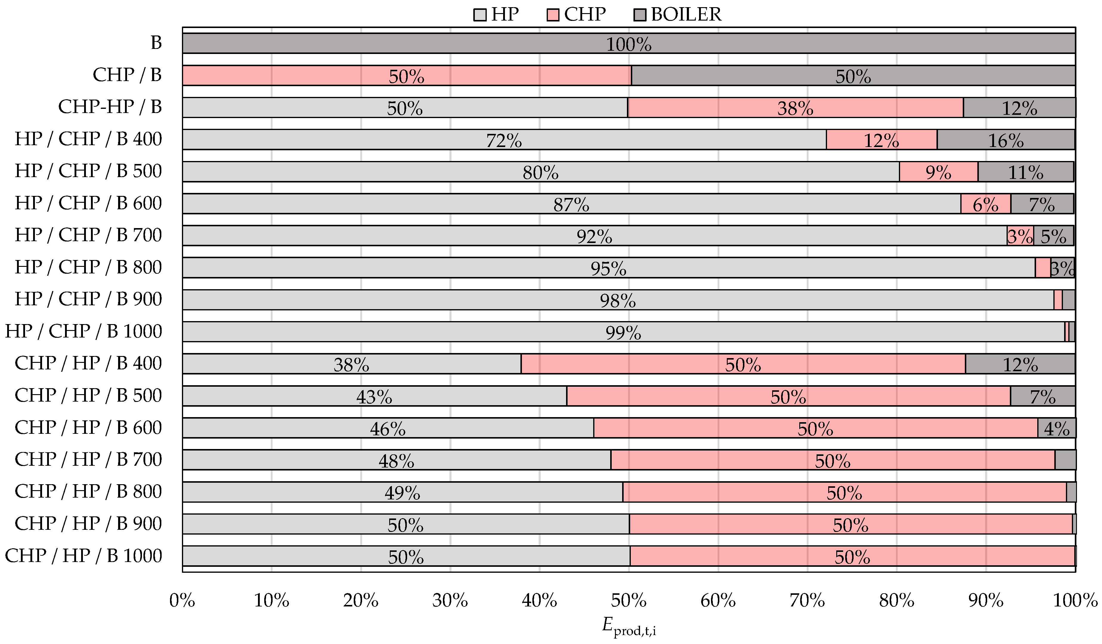
2.2.3. Systems with a Gas-Fired Boiler, CHP Unit, and HP

The implementation of a water-to-water HP has been identified as a potential enhancement to the aforementioned systems. The present study considers an HP that uses water from a nearby river as a heat source. The river’s length is 19 km, and the abstraction of river water is located 18 km downstream. The river’s relatively short length results in a consistent water temperature at the abstraction point, which remains almost constant throughout the year. In this case study, a constant water temperature of 8 °C was adopted. Temperature fluctuations within a few degrees Celsius would not significantly affect the efficiency of the HP during the year. The configuration of the HP is such that it is connected to the return line of the heating system immediately before the CHP unit, as illustrated in Figure 7. This configuration ensures a lower temperature of the inlet water to the HP compared to a configuration in which the HP is placed in the supply line after the CHP unit.
Different operation strategies of equipment for heat and power generation were examined through variants of the system presented in Table 3, along with the thermal capacities of HP units considered in the study. Systems B and CHP-B in the table represent previously mentioned systems with a gas-fired boiler and a gas-fired boiler with a CHP unit.
The selection of HP is based on the required water temperature in the distribution network and the temperature of the heat source. When choosing an HP, the requirements of the current European legislation on the use of fluorinated greenhouse gases were taken into account, which will prohibit the installation of devices that work with a refrigerant that has a GWP of 150 or higher from the beginning of 2030 [25]. For this reason, the choice of HP is limited to devices that are available on the market and use natural refrigerants. Depending on the required heating capacity and temperature regime, units which are considered use R717 refrigerant. A range of HP units was selected using professional software GEA RTSelect [26]. All the HP units are selected under operating conditions of water at the condenser 70/60 °C and a heat source temperature of 8 °C. The smallest of the considered HPs has a heating capacity of 400 kW and requires 141.5 kW of electrical power. The criterion for selection of this unit was to match the required electrical power to the CHP electrical power at full load. The annual duration curve for this case is presented in Figure 8. It is visible that CHP with HP can cover the heating energy requirement for 7000 h in the year. Larger units are selected in increments of 100 kW heating capacity up to 1000 kW. Performance data and efficiency metrics for the HPs under variable temperature conditions and partial load operations, which are acquired using professional software, were used to simulate the operation of HPs using Trnsys Type 581 [22].
In the HP/CHP/B system, the HP has the priority for heat production. When the HP cannot achieve the required water temperature, the CHP unit is activated, followed by the boiler as needed. The HP draws electricity from the grid, while the electricity generated by the CHP unit is sold back to the grid. In the CHP/HP/B system, the CHP unit has heat production priority. When it cannot reach the necessary water temperature, the HP is switched on, followed by the boiler if required. Like the previous system, the HP uses grid electricity, and the electricity produced by the CHP unit is sold to the grid. In the CHP-HP/B system, the CHP unit and the HP operate simultaneously and adjust to maintain water temperature in the system. The HP’s load is adjusted so that its required electrical power matches that of the CHP unit. The electricity produced by the CHP unit is used only for the HP operation.

2.2.4. Operational Cost Components: Energy, Equipment, and Maintenance

Electricity and natural gas are the energy sources considered in the analysis. The price of electricity varies depending on whether the energy is taken from the grid or delivered to the grid. In Croatia, the price of electricity for enterprise customers at medium voltage is set at 0.174 €/kWh for the high tariff and 0.105 €/kWh for the low tariff, as of 1 January 2025. The peak power charge is 3.865 €/kW, according to the National distributor for enterprise customers [27]. The price for electricity delivered to the grid is set at 0.125 €/kWh, as per the national legislation [28]. These electricity prices have been adopted for Scenario 1. A comparison of these prices with current prices reveals that at the beginning of 2024, the former was approximately 10% lower. For the second scenario, the electricity prices in effect at that time were adopted, with a high tariff of 0.161 €/kWh, a low tariff of 0.093 €/kWh, and a peak power charge of 3.451 €/kW, by the national distributor for enterprise customers [27]. The price for electricity delivered to the grid is set at 0.114 €/kWh by national legislation [28]. The electricity prices assumed for Scenario 3 are equivalent to those in Scenario 1. Heat energy producers may also have a different contractual model for electricity pricing, but this scenario is not included in this analysis because of business confidentiality.
The price of natural gas has undergone significant fluctuations in recent years. In this paper, the price of natural gas is analysed within three distinct scenarios. The gas price currently applied by the Republic of Croatia is utilised in Scenario 1. The gas price for heat producers is set at the same level as the purchase price, as defined by national guidelines [29]. For Scenario 1, a gas price of 0.0502 €/kWh was adopted, as reported by the Central European Gas HUB (CEGH) [30]. For Scenario 2, a gas price of 0.030 €/kWh was implemented, as observed at the beginning of 2024. The third scenario involved a gas price of 0.100 €/kWh, representing a substantial increase in gas costs. The highest average monthly gas price on the CEGH during 2022 was recorded in August 2022, reaching approximately 0.345 €/kWh. This surge was driven by supply disruptions and geopolitical tensions linked to the 2022 energy crisis.
In order to facilitate the comparison of scenarios, an indicator IC, which represents the electricity-to-gas price ratio, has been introduced. It is calculated using the mean electricity price.
IC = Cee(mean)/Cg
The HP requires heat from a heat source for its operation. The analysis considered the use of water from a nearby river as a heat source. The fee for using river water is 0.013 €/m3. Electricity, gas, and water use prices, as well as corresponding electricity-to-gas price indicators by scenarios, are shown in Table 4.
Systems with a boiler and CHP unit (B and CHP/B systems) have already been built, so the system’s investment will not be considered. In contrast, investment costs for the proposed systems incorporating HP vary depending on the installed capacity. These costs were estimated based on data obtained from equipment manufacturers, including heat pumps, circulation pumps, and piping to the water abstraction point, as well as the associated labour costs for installation.
The connection of electrical equipment to the medium-voltage grid operated by the National distributor is classified as a complex interconnection; therefore, the grid connection cost has been incorporated [31]. Total investment costs as a function of the installed HP capacity are presented in Table 5.
Maintenance costs were considered for all evaluated systems. The maintenance costs for the gas-fired boilers are based on the actual maintenance costs for the boilers in system B, which amount to 100.000 € per year. The specific boiler maintenance cost, with a value of 0.031 €/kWh, is calculated by dividing the annual maintenance cost by the total thermal energy produced by the boilers (3226 MWh). The maintenance costs for gas-fired boilers in other systems are calculated according to the thermal energy produced by the boilers in each system. Maintenance costs for systems with gas-fired CHP units are calculated as 0.0138/kWh of electricity produced [32]. For systems integrating HPs, maintenance costs are determined as 4% of HP’s investment value.

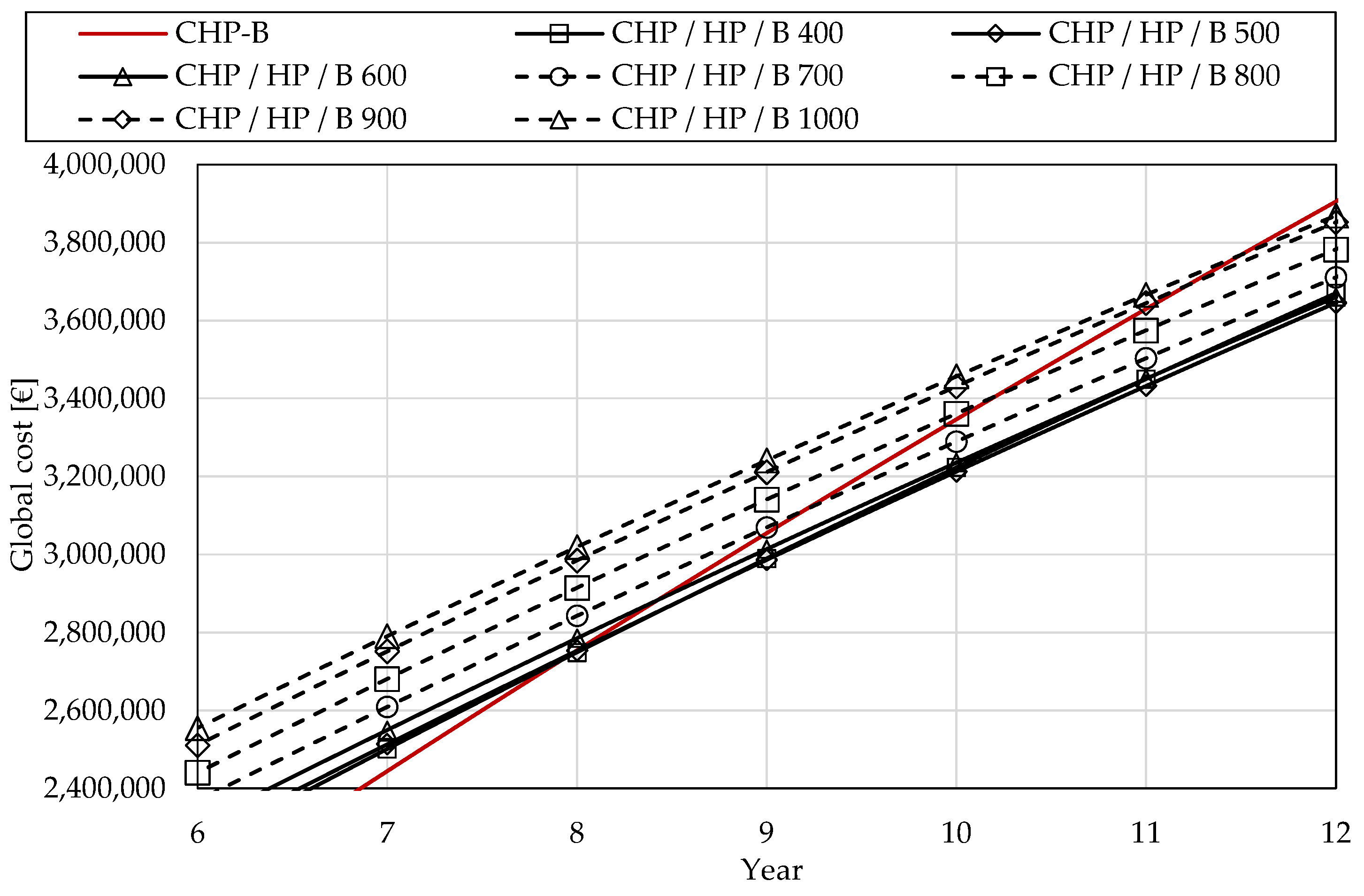
3. Results and Discussion

Dynamic simulations were used to determine the performance of each system. Among the many results that dynamic numerical simulation can provide, for this analysis, it was important to determine the energy flows of required and produced thermal energy by each generator, as well as the electricity taken and exported to the distribution network. The structure of the thermal energy produced in systems is shown in Figure 9. System B is based on the application of a natural gas boiler, which, as the results show, fully meets the system’s thermal energy requirements. By introducing a CHP unit sized to cover base heating load while retaining the existing boiler (CHP/B system) and giving priority to the CHP unit, it is possible to cover half of the required heating needs with the CHP unit. The simultaneous operation of a 400 kW medium-scale HP and CHP unit, which has priority over boiler operation (CHP-HP/B) results in half of the thermal energy produced by the HP, 38% by the CHP unit, and 12% by the boiler. In this variant, the HP is operated according to the available electrical power from the CHP unit, resulting in a slightly larger share for the HP. When the priority in the production of heat energy is given to HP (HP/CHP/B systems), the greatest proportion of thermal energy is produced by the HP (72 to 99%), followed by the CHP unit, and the boiler. The share of energy produced by the HP depends on the installed capacity of the unit. The operation of a boiler or CHP unit is necessary for periods of operation at peak load. In variants where the system is configured to prioritize the operation of the CHP unit (CHP/HP/B systems), 50% of the thermal energy is produced by the CHP unit, while the HP, depending on the size of the unit, covers 38% to 50% of the energy requirement. Generally, in scenarios where a larger HP unit has been installed, only a small or negligible percentage of thermal energy is produced by the boiler. So, an HP sized to 43% of the heating load could replace a gas boiler in conditions of the reference year.
The share of renewable energy sources in the DH systems is determined based on simulation results, as illustrated in Figure 10. Systems incorporating only a boiler or a combination of boiler and CHP units do not utilize renewable energy sources. RES contributions are observed exclusively in configurations that include an HP. Systems where operational priority is assigned to the HP demonstrate a higher RES share compared to those where the CHP unit has priority. Moreover, the RES share increases with the installed HP capacity. The highest RES share, reaching 67%, is observed in the HP/CHP/B configuration, where a 1000 kW HP operates as the primary heat source. Even higher RES contributions could be achieved if the electricity consumed by the HP were sourced from on-site renewable generation.
The indicators of primary energy consumption (EPI) and CO2 emissions (mCO2) for analysed DH systems are shown in Figure 11. The introduction of a CHP unit to the DH system has been shown to have limited effectiveness in reducing primary energy consumption and CO2 emissions, with no significant decrease observed in either variable. The highest energy performance index (EPI) recorded was 121 kWh/m2 in system B, while system CHP/B demonstrated an EPI of 114 kWh/m2. The integration of a medium-sized HP unit within the system has been observed to result in a substantial reduction in primary energy consumption. In the HP/CHP/B systems, where the HP has operational priority, the EPI is reduced up to 70% (1000 kW HP unit) compared to the base system with the boiler and CHP unit. Further reductions in EPI could be achieved through the deployment of large-scale HP units. In contrast, when the CHP unit holds operational priority, the EPI reduction is less substantial, ranging from 41% with a 400 kW HP to 48% with a 1000 kW HP.
The highest CO2 emissions are produced in systems that utilize natural gas exclusively: 1443 tons of CO2 per year in the gas-fired boiler system, and 1360 tons of CO2 in the CHP/B system. In the systems where HP takes operational priority, annual emissions are, depending on the installed HP size, reduced in range from 71 to 82% compared to the CHP/B system. In the systems where CHP takes operational priority, annual emissions are reduced by a smaller amount compared to the systems with HP operational priority: reduction is in the range from 55 to 61% compared to the CHP/B system. Similar annual CO2 emissions are achieved when the electricity generated by the CHP is utilised for the HP operation (CHP-HP/B system), which results in 572 tons of CO2 emissions per year, representing a 58% reduction relative to the CHP-B system.
A full lifecycle assessment (LCA) was not conducted due to the unavailability of detailed data on materials, manufacturing, and supply chains. However, according to a recent LCA study on heat pumps [33], the use phase accounts for approximately 94.6% of total emissions, with other phases contributing marginally (~6%). Therefore, the operational CO2 emissions presented in this study provide a reliable representation of the overall environmental impact.
The cost analysis is based on the assumption that the DH system operator invests its funds in the purchase of new equipment, i.e., does not make a loan for the investment. The initial costs for equipment, grid connection, maintenance, and purchased water for HPs are the same for all three price scenarios. However, the energy price differs due to different electricity and natural gas prices. The levelized cost of energy for heating CLH is presented in Figure 12.
In Scenarios 1 and 2, which reflect current and recent energy price conditions, the baseline DH system configuration CHP/B is found to be the most cost-effective. It achieves the lowest levelized cost of heating CLH among all evaluated configurations, with values of 0.037 €/kWh and 0.019 €/kWh, respectively. Under these scenarios, high electricity prices favour the operation of the CHP unit, particularly due to the ability to export electricity to the grid. Consequently, systems incorporating HPs exhibit higher CLH values compared to the baseline system.
The increase in costs is most pronounced in configurations where the HP has operational priority, with CLH rising by up to 75% in Scenario 1 and by more than 200% in Scenario 2. Even in configurations where the CHP unit retains operational priority, the CLH still increases by up to 31% in Scenario 1 and up to 88% in Scenario 2. The cost increase is more significant in systems with higher installed HP capacity. These results indicate that, under the current and recent electricity price conditions modelled in Scenarios 1 and 2, the installation of HPs, particularly large-scale units, is not economically viable. Additionally, the operation of a system relying solely on a gas-fired boiler under these pricing conditions proves economically unviable due to high fuel costs and the absence of electricity export revenues.
In contrast, Scenario 3 assumes a more favourable electricity price structure. Under this scenario, all system variants incorporating HPs achieve lower specific heating costs than the baseline DH system, which records a CLH of 0.110 €/kWh. Cost reductions are more substantial in configurations where the HP has operational priority, with the greatest reduction of 33% observed in the system featuring the largest HP unit (1000 kW). As anticipated, systems prioritising CHP operation show more modest cost reductions, up to 12% compared to the baseline. These results suggest that under favourable electricity pricing conditions, the implementation of medium- to large-scale HPs may be economically feasible.
Accordingly, the long-term economic analysis focuses on Scenario 3, which reflects favourable electricity pricing conditions. To assess the feasibility of integration of HPs under these conditions, global costs over a 20-year period are calculated for each system configuration. The results for systems with prioritised operation of HP and CHP-HP are presented in Figure 13. Among these configurations, the CHP-HP/B system exhibits the highest levelized cost of heating CLH, resulting in the longest payback period of 7 years. In contrast, systems with prioritised HP operation demonstrate improved economic performance, achieving payback periods ranging from 4 to 6 years. The shortest payback period—4.7 years—is observed in the system with a 600 kW HP, followed closely by the 500 kW and 700 kW configurations.
Figure 14 illustrates the results for systems with prioritised CHP operation under Scenario 3. Due to higher CLH values, these configurations exhibit longer payback periods compared to those with prioritised HP operation. The shortest payback period in this group is 8 years, recorded for systems with 400 kW and 500 kW HP units. As the installed HP capacity increases, the payback period correspondingly extends, reaching up to 11.5 years for the system with a 1000 kW HP unit. Overall, the payback period increases with HP capacity. Furthermore, configurations in which the HP is integrated without operational priority are found to be economically unviable under the given conditions.

4. Conclusions

This study examined the viability of integrating medium-scale HPs into existing third-generation DH systems already comprising CHP units and gas boilers. A dynamic simulation model was developed to realistically represent the behaviour of the production, distribution, and consumption subsystems using commercially available technologies. The research assessed multiple system configurations and operational strategies under varying energy price scenarios to determine the energy, environmental, and economic impacts of HP integration.
The findings demonstrate that incorporating HPs into DH systems can significantly enhance environmental performance. When the HP is given operational priority, systems achieve substantial reductions in primary energy consumption (up to 70%) and CO2 emissions (up to 82%) compared to the baseline configuration with CHP and boiler. Additionally, these configurations result in a higher share of RES, reaching up to 67%, especially with larger HP capacities. However, some reliance on the boiler or CHP remains necessary to cover peak thermal demands.
Despite these advantages, economic feasibility is highly dependent on the prevailing electricity and gas price ratios. Under current and recent pricing conditions in Croatia (Scenarios 1 and 2), where electricity prices remain high relative to gas, systems with HPs, particularly those with larger capacities, incur higher heating costs and longer payback periods. In these scenarios, configurations prioritising CHP operation remain the most cost-effective due to the opportunity to export electricity. The cost of heating in HP-priority systems can rise by up to 75% under such conditions, making them economically unviable in the short term.
Conversely, Scenario 3, characterised by more favourable electricity pricing, demonstrates that systems prioritising HP operation can achieve lower levelized costs of heating than the baseline CHP and boiler setup. In this scenario, HP systems exhibit payback periods of 4 to 6 years, with the shortest observed at 4.7 years for a 600 kW HP, confirming the potential for economic viability under supportive market conditions.
With regard to the generalisation of the results, it is important to note that the economic viability of HP integration depends significantly on local energy prices. Electricity-to-gas price ratios vary widely across Europe, and under conditions of high electricity prices, heat pumps become less economically attractive, while more favourable ratios enhance their competitiveness. In colder climates, the annual thermal energy demand of DH systems would be higher than in the Rijeka case and, conversely, lower in milder climates. However, since the analysed HP uses river water as a heat source, with relatively stable temperatures year-round, its coefficient of performance (COP) remains largely unaffected by ambient air temperature. Although specific national policies (e.g., carbon pricing or subsidies) may influence fuel price dynamics, they would not alter the technical performance of the system. Therefore, while the energy demand and cost-effectiveness may vary across regions, the technical findings remain broadly applicable in similar system configurations.
In conclusion, the integration of medium-scale HPs into DH systems can offer considerable environmental and energy efficiency benefits, especially when sized to cover a significant portion of the heating load. However, their economic justification is conditional on energy market structures. For widespread adoption, policy support or market reforms that reduce electricity prices relative to gas, alongside technical measures such as lowering system supply temperatures, will be essential. Further optimisation of DH system configurations and the adoption of low-temperature networks could enhance both the efficiency and cost-effectiveness of HP integration in future DH systems.

Future Work and Research Outlook

Several directions for future research have been identified to enhance the modelling framework and its decision-support capabilities:
1.
Methodological enhancement through optimisation and hybrid approaches
To improve model adaptability and strengthen its decision-making value, future work will integrate optimisation algorithms and hybrid data-driven methods. These enhancements will enable automated identification of optimal system configurations and control strategies under varying boundary conditions, potentially improving both energy efficiency and economic outcomes.
2.
Advanced financial modelling under dynamic market conditions
The current financial analysis assumes self-financing and static energy prices. Future studies will incorporate more realistic scenarios, including mixed financing models (e.g., loans, subsidies) and dynamic electricity and gas pricing. This will offer a more robust foundation for investment planning in an evolving energy market and policy landscape.
3.
Progressive integration into fourth-generation DH paradigms
While this study supports the transition toward low-temperature DH through the inclusion of HPs, achieving full alignment with fourth-generation DH principles will require further development. These include lowering building-level supply temperatures and integrating on-site renewable electricity sources, such as PV, to power HPs. Future research will address these aspects to support broader decarbonisation and system flexibility.

Author Contributions

Conceptualisation, D.P., B.D., B.P., and V.M.-V.; methodology, D.P. and B.D.; software and simulation, D.P., B.D., and V.M.-V.; formal analysis, D.P.; investigation, D.P.; resources, D.P. and B.D.; writing—original draft preparation, D.P., B.D., and V.M.-V.; writing—review and editing, D.P., B.D., and V.M.-V.; visualisation, D.P., B.D., and V.M.-V.; supervision, B.D.; All authors have read and agreed to the published version of the manuscript.

Funding

This work has been supported by the University of Rijeka under the project Investigating the potential for the renewal of district heating systems using dynamic simulations (uniri-iskusni-tehnic-23-146).

Institutional Review Board Statement

Not applicable.

Informed Consent Statement

Not applicable.

Data Availability Statement

Dataset available on request from the authors.

Conflicts of Interest

The authors declare no conflicts of interest.

Abbreviations

The following abbreviations are used in this manuscript:
Aarea (m2)
Ccost (€)
COPcoefficient of performance (-)
Eenergy (kWh)
EPprimary energy (kWh)
EPIprimary energy indicator (kWh/m2)
fenergy factor (-)
SCOPseasonal coefficient of performance (-)
RESshare of renewable energy (-)
mmass (t)
CHP combined heat and power
COP coefficient of performance
DH district heating
DHW domestic hot water
GIS geographic information system
GWP global warming potential
HP heat pump
PV photovoltaic
RES renewable energy sources
Subscripts
a annual
Bboiler
cons consumption
d discount
ee electricity
em emission
expexported
g gas
i energy carrier
I initial investment
imp imported
LHlevelized cost of heat
nren non-renewable
p year
prod produced
r discount rate
s system
ttotal
τ accounting period

References

  1. Lund, H.; Werner, S.; Wiltshire, R.; Svendsen, S.; Thorsen, J.E.; Hvelplund, F.; Mathiesen, B.V. 4th Generation District Heating (4GDH). Energy 2014, 68, 1–11. [Google Scholar] [CrossRef]
  2. Alarnaot Alarnaout, G.; Navarro-Esbrí, J.; Mota-Babiloni, A. Operational, Economic, and Carbon Footprint Feasibility of a Moderately-High-Temperature Heat Pump as an Alternative to Conventional Boilers in Various Scenarios. Energy Convers. Manag. 2024, 309, 118424. [Google Scholar] [CrossRef]
  3. Požgaj, D.; Pavković, B.; Delač, B.; Glažar, V. Retrofitting of the District Heating System Based on the Application of Heat Pumps Operating with Natural Refrigerants. Energies 2023, 16, 1928. [Google Scholar] [CrossRef]
  4. Volkova, A.; Krupenski, I.; Pieper, H.; Ledvanov, A.; Latõšov, E.; Siirde, A. Small Low-Temperature District Heating Network Development Prospects. Energy 2019, 178, 714–722. [Google Scholar] [CrossRef]
  5. Lund, H.; Østergaard, P.A.; Chang, M.; Werner, S.; Svendsen, S.; Sorknæs, P.; Thorsen, J.E.; Hvelplund, F.; Mortensen, B.O.G.; Mathiesen, B.V.; et al. The Status of 4th Generation District Heating: Research and Results. Energy 2018, 164, 147–159. [Google Scholar] [CrossRef]
  6. Yu, H.; Bergaentzlé, C.; Petrović, S.; Ahlgren, E.O.; Johnsson, F. Combining Techno-Economic Modeling and Spatial Analysis for Heat Planning in Rural Regions: A Case Study of the Holbæk Municipality in Denmark. Smart Energy 2024, 14, 100144. [Google Scholar] [CrossRef]
  7. Reiter, P.; Poier, H.; Holter, C. BIG Solar Graz: Solar District Heating in Graz—500,000 m2 for 20% Solar Fraction. Energy Procedia 2016, 91, 578–584. [Google Scholar] [CrossRef]
  8. Popovski, E.; Aydemir, A.; Fleiter, T.; Bellstädt, D.; Büchele, R.; Steinbach, J. The Role and Costs of Large-Scale Heat Pumps in Decarbonising Existing District Heating Networks—A Case Study for the City of Herten in Germany. Energy 2019, 180, 918–933. [Google Scholar] [CrossRef]
  9. Aste, N.; Caputo, P.; Del Pero, C.; Ferla, G.; Huerto-Cardenas, H.E.; Leonforte, F.; Miglioli, A. A Renewable Energy Scenario for a New Low Carbon Settlement in Northern Italy: Biomass District Heating Coupled with Heat Pump and Solar Photovoltaic System. Energy 2020, 206, 118091. [Google Scholar] [CrossRef]
  10. Barco-Burgos, J.; Bruno, J.C.; Eicker, U.; Saldaña-Robles, A.L.; Alcántar-Camarena, V. Review on the Integration of High-Temperature Heat Pumps in District Heating and Cooling Networks. Energy 2022, 239, 122378. [Google Scholar] [CrossRef]
  11. Ommen, T.; Thorsen, J.E.; Markussen, W.B.; Elmegaard, B. Performance of Ultra Low Temperature District Heating Systems with Utility Plant and Booster Heat Pumps. Energy 2017, 137, 544–555. [Google Scholar] [CrossRef]
  12. Olympios, A.V.; Pantaleo, A.M.; Sapin, P.; Markides, C.N. On the Value of Combined Heat and Power (CHP) Systems and Heat Pumps in Centralised and Distributed Heating Systems: Lessons from Multi-Fidelity Modelling Approaches. Appl. Energy 2020, 274, 115261. [Google Scholar] [CrossRef]
  13. David, A.; Mathiesen, B.V.; Averfalk, H.; Werner, S.; Lund, H. Heat Roadmap Europe: Large-Scale Electric Heat Pumps in District Heating Systems. Energies 2017, 10, 578. [Google Scholar] [CrossRef]
  14. Levihn, F. CHP and Heat Pumps to Balance Renewable Power Production: Lessons from the District Heating Network in Stockholm. Energy 2017, 137, 670–678. [Google Scholar] [CrossRef]
  15. Ommen, T.; Markussen, W.B.; Elmegaard, B. Heat Pumps in Combined Heat and Power Systems. Energy 2014, 76, 989–1000. [Google Scholar] [CrossRef]
  16. Capone, M.; Guelpa, E.; Verda, V. Optimal Installation of Heat Pumps in Large District Heating Networks. Energies 2023, 16, 1448. [Google Scholar] [CrossRef]
  17. Helin, K.; Syri, S.; Zakeri, B. Improving District Heat Sustainability and Competitiveness with Heat Pumps in the Future Nordic Energy System. Energy Procedia 2018, 149, 455–464. [Google Scholar] [CrossRef]
  18. TRNSYS Transient System Simulation Tool. 2013. Available online: https://www.trnsys.com/ (accessed on 15 May 2025).
  19. Primary Energy Factors for Republic of Croatia. Available online: https://mpgi.gov.hr/UserDocsImages/dokumenti/EnergetskaUcinkovitost/meteoroloski_podaci/FAKTORI_primarne_energije.pdf (accessed on 3 February 2022).
  20. DIN EN 12831-1:2017-09; Energy Performance of Buildings—Method for Calculation of the Design Heat Load. DIN Media GmbH: Berlin, Germany, 2017.
  21. DIN 4708-2:1994-04; Zentrale Wassererwärmungsanlagen; Regeln Zur Ermittlung Des Wärmebedarfs Zur Erwärmung von Trinkwasser in Wohngebäuden. DIN Media GmbH: Berlin, Germany, 1994; p. 7.
  22. The TESS Component Libraries 17; TESS: Madison, WI, USA, 2021.
  23. Technology Brochure-CHP Units for Heat and Power—Vitobloc; Viessmann GmbH: Allendorf, Germany, 2019.
  24. Delač, B.; Pavković, B.; Lenić, K.; Mađerić, D. Integrated Optimization of the Building Envelope and the HVAC System in NZEB Refurbishment. Appl. Therm. Eng. 2022, 211, 118442. [Google Scholar] [CrossRef]
  25. Regulation (EU) 2024/573 of the European Parliament and of the Council of 7 February 2024 on Fluorinated Greenhouse Gases, Amending Directive (EU) 2019/1937 and Repealing Regulation (EU) No 517/2014; 2024. Available online: https://eur-lex.europa.eu/eli/reg/2024/573/oj/eng (accessed on 15 May 2025).
  26. GEA RTSelect Configuration and Engineering Software, Version 13. 9. 2.; GEA Group: Düsseldorf, Germany, 2025.
  27. HEP Elektra d.d. National Electricity Tariff Items for Supply the Enterprise Consumers. Available online: https://www.hep.hr/elektra/poduzetnistvo/tarifne-stavke-cijene-1578/1578 (accessed on 24 April 2025).
  28. Official Gazette of the Republic of Croatia NN RH No. 83/2023—The Act on Amendments to the Law on RES and High-Efficiency Cogeneration. Available online: https://narodne-novine.nn.hr/clanci/sluzbeni/2023_07_83_1298.html (accessed on 24 April 2025).
  29. Official Gazette of the Republic of Croatia NN RH No. 31/2023—The Regulation on Eliminating Market Disturbances. Available online: https://narodne-novine.nn.hr/clanci/sluzbeni/2023_03_31_531.html (accessed on 24 April 2025).
  30. Central European Gas Hub. Available online: https://www.cegh.at/en/ (accessed on 24 April 2025).
  31. National Electricity Operator HEP Elektra d.d. Complex Interconnection to the Medium-Voltage Grid. Available online: https://www.hep.hr/ods/pristup-mrezi/prikljucenje-na-mrezu-28/slozeno-prikljucenje/239 (accessed on 24 April 2025).
  32. Schaumann, G.; Schmitz, K.W. Kraft-Wärme-Kopplung, 4th ed.; Springer: Berlin/Heidelberg, Germany, 2010. [Google Scholar]
  33. Famiglietti, J.; Acconito, L.; Arpagaus, C.; Toppi, T. Environmental Life Cycle Assessment of Industrial High-Temperature to Residential Small-Size Heat Pumps: A Critical Review. Energy Convers. Manag. X 2025, 26, 100947. [Google Scholar] [CrossRef]
Figure 1. Flowchart for the modelling and simulation cycle.
Applsci 15 07280 g001
Figure 2. Control logic diagram for prioritised operation of HP, CHP, and boiler (highest to lowest priority).
Applsci 15 07280 g002
Figure 3. Scheme of the energy flows in DH system.
Applsci 15 07280 g003
Figure 4. A schematic of a DH system with a gas-fired boiler.
Applsci 15 07280 g004
Figure 5. Schematic of a DH system with a gas-fired boiler and CHP unit.
Applsci 15 07280 g005
Figure 6. The annual duration of the required heating capacity and energy that can be covered by the operation of the CHP unit.
Applsci 15 07280 g006
Figure 7. Schematic of a DH system with a gas-fired boiler, CHP and HP units.
Applsci 15 07280 g007
Figure 8. The annual duration of the required heating capacity and energy that can be covered by the operation of the CHP and HP unit with 400 kW heating capacity.
Applsci 15 07280 g008
Figure 9. The structure of the thermal energy produced in systems.
Applsci 15 07280 g009
Figure 10. The share of RES by the systems.
Applsci 15 07280 g010
Figure 11. Indicators of primary energy consumption (EPI) and CO2 emission.
Applsci 15 07280 g011
Figure 12. Comparison of system performance in different price variants in terms of (a) absolute values of levelized cost of energy for heating; (b) values of levelized cost of energy for heating relative to the base DH system.
Applsci 15 07280 g012
Figure 13. Global costs over the considered period for systems with prioritised CHP-HP and HP operation in price Scenario 3.
Applsci 15 07280 g013
Figure 14. Global costs over the considered period for systems with prioritised CHP operation in price Scenario 3.
Applsci 15 07280 g014
Table 1. The main climate and location data and characteristics of the DH system considered in the study.
Climate dataCityRijeka (Croatia)
LongitudeE 14°26′31.834″
LatitudeN 45°19′37.427″
Design ambient temperature−8 °C
Annual average ambient temperature15.8 °C
DH dataTrench total length912 m
Fuel typeNatural gas
Annual fuel energy consumption (2019)5,069,863 kWh
Annual thermal energy supply into DH system (2019)4,410,544 kWh
Annual heating and DHW demand building (2019)3,943,144 kWh
Supply/return temperature90/70 °C
DH consumersNumber of buildings9
Heated area48,455 m2
Heated space volume145,365 m3
Internal heat gains6 W/m2
Infiltration/required ventilation rate0.48 h−1/1.32 h−1
Heating operationInterrupted during the night
Heating temperature set point20 °C
Number of apartments601
Number of persons1455
DHW set point45 °C
Table 2. The technical specifications of the CHP unit with a gas engine.
CHP Load
%
Electrical Output
kW
Heating Output
kW
Fuel Use
kW
100140209384
75105171310
5070130227
Table 3. Overview of system variants considered in the study: configuration, operational priority, and energy utilisation.
SystemPriority in Thermal Energy ProductionHP
Capacity
Electricity for HP
Operation
Produced Electricity from CHP
BBoiler---
CHP/BCHP--Sold to grid
CHP-HP/BCHP-HP, boiler400 kWFrom CHPUsed for HP
HP/CHP/BHP, CHP, boiler400 kW–1000 kW (100 kW
increment)
From gridSold to grid
CHP/HP/BCHP, HP, boiler400 kW–1000 kW (100 kW
increment)
From gridSold to grid
Table 4. Energy prices and electricity-to-gas price indicator.
Scenario 1Scenario 2Scenario 3Unit
High LowHigh LowHigh Low
Electricity0.1740.1050.1610.0930.1740.105€/kWh
3.8653.4513.865€/kW
Gas0.0500.0300.100€/kWh
Water0.0130.0130.013€/m3
Ic2.84.21.4-
Table 5. Investment costs for systems.
SystemHP CapacityInvestment Cost
CHP-HP/B
HP/CHP/B
CHP/HP/B
400 kW540,000 €
500 kW610,000 €
600 kW690,000 €
700 kW760,000 €
800 kW830,000 €
900 kW900,000 €
1000 kW980,000 €
Disclaimer/Publisher’s Note: The statements, opinions and data contained in all publications are solely those of the individual author(s) and contributor(s) and not of MDPI and/or the editor(s). MDPI and/or the editor(s) disclaim responsibility for any injury to people or property resulting from any ideas, methods, instructions or products referred to in the content.

