Article

A Novel Adaptive Transient Model of Gas Invasion Risk Management While Drilling

1
Engineering Technology Management Department, Jianghan Oilfield Company, Qianjiang 433124, China
2
College of Petroleum Engineering, China University of Petroleum (Beijing), Beijing 102249, China
3
Drilling Engineering Technology Research Center, Sinopec Petroleum Engineering Technology Research Institute Co., Ltd., Beijing 102206, China
4
College of Mechanical and Transportation Engineering, China University of Petroleum (Beijing), Beijing 102249, China
*
Author to whom correspondence should be addressed.
Appl. Sci. 2025, 15(13), 7256; https://doi.org/10.3390/app15137256
Submission received: 21 April 2025 / Revised: 17 June 2025 / Accepted: 23 June 2025 / Published: 27 June 2025
(This article belongs to the Special Issue Development and Application of Intelligent Drilling Technology)

Abstract

The deep and ultra-deep oil and gas resources often have the characteristics of high temperature and high pressure, with complex pressure systems and narrow safety density windows, so risks such as gas invasion and overflow are easy to occur during the drilling. In response to the problems of low management efficiency and large gas kick by traditional gas invasion treatment methods, this paper respectively established and compared three intelligent control models for bottom hole pressure (BHP) based on a PID controller, a fuzzy PID controller, and a fuzzy neural network PID controller based on the non-isothermal gas–liquid–solid three-phase transient flow heat transfer model in the annulus. The results show that compared with the PID controller and the fuzzy PID controller, the fuzzy neural network PID controller can adjust the control parameters adaptively and optimize the control rules in real-time; the efficiency of the fuzzy neural network PID controller to deal with a gas kick is improved by 45%, and the gas kick volume in the process of gas kick is reduced by 63.12%. The principal scientific novelty of this study lies in the integration of a fuzzy neural network PID controller with a non-isothermal three-phase flow model, enabling adaptive and robust bottom hole pressure regulation under complex gas invasion conditions, which is of great significance for reducing drilling risks and ensuring safe and efficient drilling.

1. Introduction

Controlling bottom hole pressure (BHP) in real-time during drilling operations is crucial for efficient drilling performance and risk mitigation [1,2,3]. Managed pressure drilling (MPD) technology aims to maintain BHP within a safe pressure window by dynamically adjusting the choke valve at the wellhead [4,5,6]. This approach enables the early circulation of gas influx without shutting in the well, improving the operational safety and efficiency in complex formations [7,8].
In recent years, numerous control strategies for MPD have been developed, including classical PID controllers and advanced methods such as nonlinear model predictive control (NMPC) and L1 adaptive control. Riet et al. developed an automatic MPD system to treat gas kicks efficiently [9]. Pedersen et al. used a linear model predictive control (MPC) algorithm to regulate pump flow and choke pressure to manage and maintain BHP [10]. Nygaard, Nandan, and Sule et al. proposed a method of BHP control using the NMPC algorithm, which can track BHP set-point during normal operations and switch to flow control mode automatically in abnormal situations [11,12,13,14,15]. Li and Hessam et al. designed an integrated estimator to calculate BHP in real-time and developed an L1 adaptive controller to regulate BHP automatically [16,17]. Li et al. presented a robustness analysis framework for pressure control in MPD and an approach to search for controller tuning parameters [18]. In addition, Sule et al. and Nandan et al. used fault trees, Bayesian networks, multiple linear controllers, etc., to regulate BHP [19,20,21]. Sheikhi et al. proposed a nonlinear predictive generalized minimum variance (NPGMV) controller to regulate BHP [22]. These advanced methods can provide accurate BHP tracking, especially in abnormal situations. However, they rely heavily on accurate and often complex multiphase flow models, which are governed by nonlinear partial differential equations (PDEs) [23,24]. As a result, they often suffer from high computational burden, model sensitivity, and limited robustness in real-time applications.
For the PID controller, Zhou presents three control schemes to stabilize the BHP prole, including PI control, feed-forward PI control, and adaptive feed-forward PI control, and the results show that the adaptive PI controller exhibits less tracking error and fewer oscillations [25,26,27,28]. Erge et al. considered the thixotropic behavior of drilling fluids and developed a preview-based feedback PI controller to regulate BHP [29]. Godhavn developed a nonlinear hydraulic model based on PID capturing only the main pressure and flow dynamics [30]. Siahaan et al. established an adaptive PID switching controller to regulate BHP, which can choose the right PID parameter based on the data measurement [31]. Vega et al. identified the process of MPD as a low-order transfer function model, generating the gain, the time constant, and the delay to set the PID controller for BHP [32]. Zhang et al. put forward an improved particle swarm optimization PID neural network (IPSO-PIDNN) model to control BHP [33]. Gorjizadeh et al. developed a fuzzy controller, which satisfies physical/operational limitations [34]. The PID controller has the advantages of a simple structure, independent control parameters, good adaptability, and strong robustness. It can exert its control ability to the maximum effect on complex models and is widely used in the field of the petroleum industry. Nevertheless, traditional PID controllers require offline tuning and fixed parameters, which limit their adaptability in dynamically changing downhole environments.
Most of the existing studies are based on the gas–liquid two-phase flow model to control BHP [35,36], while studies considering gas–liquid–solid three-phase flow in the wellbore annulus are limited. The multiphase flow model is a hyperbolic partial differential equation (PDE) equation, and the solution of the gas–liquid–solid three-phase flow model is more complex. To reduce the control complexity while maintaining accuracy, PID control is still a suitable choice. However, traditional PID controllers require predefined parameters, do not adapt to changing targets, and exhibit poor responsiveness and significant overshoot in BHP regulation [25].
In recent years, machine learning has been widely applied in various industrial scenarios [37]. Among them, artificial neural networks have strong self-learning and nonlinear approximation capabilities, enabling the real-time adjustment of PID parameters. Fuzzy control provides reasoning capability based on human knowledge. However, traditional fuzzy controllers often rely on fixed fuzzy rule tables defined offline, which lack adaptability in dynamic downhole conditions. To overcome these limitations, this paper proposes a fuzzy neural network PID controller that integrates neural network adaptability, fuzzy logic reasoning, and PID simplicity. This controller can learn and optimize fuzzy rules online according to real-time system feedback, providing improved adaptability and robustness.
Compared to NMPC and L1 adaptive control, the proposed fuzzy neural network PID controller reduces the dependence on accurate physical models, lowers the computational load, and improves the numerical stability during real-time operation in complex multiphase environments. Based on the three-phase flow mechanism in the wellbore, the controller is developed to regulate BHP, and its performance is compared with that of the conventional PID controller and fuzzy PID controller during gas kick scenarios. Simulation results demonstrate that the proposed controller achieves higher accuracy, faster response, and better control stability in BHP regulation.
Compared to previous studies that mostly relied on simplified two-phase or isothermal models, this work presents a novel integration of a fuzzy neural network PID controller with a full-scale non-isothermal gas–liquid–solid three-phase model. This integration allows for online rule optimization, improved adaptability, and real-time robustness for BHP control during gas invasion scenarios, which constitutes the core scientific contribution of this study.

2. Multiphase Flow Model

2.1. Assumed Conditions

To reduce the complexity of modeling and solving, the following reasonable assumptions are made:
(1) After the high-temperature cuttings break away from the bottom and enter the annulus, heat exchange with the annulus fluid is completed instantly, forming a heat balance.
(2) The annular wall resistance of all cuttings is the same, which is equal to the wall resistance of particles at the center of the annulus.
(3) The three phases of gas, liquid, and solid at the same position are in real-time temperature and pressure balance.
(4) Wall resistance does not affect the radial distribution of cuttings in the annulus.
(5) The cuttings concentration and annulus wall resistance do not affect the two-phase boundary conditions in the gas–liquid mainstream area [35,36].
(6) The bit does not affect the bottom hole flow and heat transfer processes.
(7) This study assumes drilling in high-temperature and high-pressure gas formations without formation fluids.
(8) The formation pressure is always higher than the annular pressure by 2 MPa.

2.2. Governing Equations

(1) Mass conservation equation of multiphase flow
The mass conservation equation ensures that the total mass of the gas–liquid–solid mixture is conserved during transient flow through the annulus:
ρ m t + ( ρ m V m ) z = Γ m
where ρ m is the density of a gas–liquid–solid three-phase mixture in k g / m 3 ; t is the time in s ; V m is the average flow rate of the gas–liquid–solid three-phase mixture in m / s ; z is the depth in m ; and Γ m is the mass exchange between a gas–liquid–solid three-phase mixture, Γ m = 0 , in k g / m 3 · s .
The density and flow velocity of the mixture are the average density and flow velocity of the gas, liquid, and solid, so the change in mass with time and well depth can be expressed as follows:
ρ m t = ( ρ G α G ) t + ( ρ L α L ) t + ( ρ S α S ) t
( ρ m V m ) z = ( ρ G α G V G ) z + ( ρ L α L V L ) z + ( ρ S α S V S ) z
where α is the volume fraction, and subscripts G, L, and S indicate the gas, liquid, and solid phases.
The mass exchange of the three phases of gas, liquid, and solid includes gas–liquid mass exchange, gas–solid mass exchange, and liquid–solid mass exchange.
Γ m = Γ GL + Γ LG + Γ GS + Γ SG + Γ SL + Γ LS
(2) Momentum conservation equation of multiphase flow
The momentum conservation equation balances the pressure forces, gravitational effects, wall friction, and inter-phase drag forces. It reflects the dynamic behavior of multiphase flow and is crucial for accurately computing the annular pressure distribution that influences BHP.
ρ m V m t + ρ m V m 2 z + P z + ρ m g cos θ + F Wm + F Im = 0
where P is the annulus pressure in P a ; g is the gravitational acceleration in m / s 2 ; θ is the well inclination angle in ° ; F W m is the wall friction force of each phase in k g / m 2 / s 2 ; F I m is the interaction force between phases in k g / m 2 / s 2 ; and the sum of the interaction force between phases is 0.
(3) Temperature of the multiphase mixture in annular
Under deep drilling gas invasion conditions, the temperature of the annular multiphase mixture is determined by the combination of its heat carried by the upward flow of the annular fluid, the heat exchange between the annular fluid and the well wall, the heat exchange between the annular fluid and the drill pipe, and the heat carried by the high-temperature rock chips at the bottom of the well, so the energy conservation of the annular mixture can be expressed by the following equation:
t ρ m α m u m + 1 2 V m 2 = ρ m α m V m g cos θ + z ρ m α m V m u m + P ρ m + 1 2 V m 2 + Q total A an + H ˙ m
where α m is the volume fraction of the mixture; u m is the internal energy of the mixture in m 2 / s 2 ; Q t o t a l is the total heat exchange between the annulus and the environment in k g · m / s 3 ; A a n is the annulus cross-sectional area in m 2 ; and H m is the enthalpy flux per unit volume in k g / m / s 3 .
The heat exchange between the annulus and the environment mainly consists of three parts: ① the heat exchange between the annulus fluid and the drill pipe; ② the heat exchange between the annulus fluid and the casing or the formation; and ③ the heat of the high-temperature rock chips at the bottom of the well itself. The total heat exchange is given by the following formula:
Q total = 2 π r dp , o h dp - an T dp T an + 2 π r ca 3 , i h an - ca 3 T ca 3 T an + π r ca 3 , i 2 R O P ρ f C f T f
where r d p , o and r c a 3 , i denote the heat transfer diameters of the annular fluid to the drill pipe and casing, respectively, in m ; h d p a n and h a n c a 3 are the convective heat transfer coefficients of the annulus to the drill pipe and the annulus to the casing, respectively, in W / m 2 / ° C ; T d p , T a n , T c a 3 , and T f denote the drill pipe wall temperature, the annular fluid temperature, the production casing temperature, and the bottom hole formation temperature, respectively, in ° C ; ROP denotes the mechanical drilling speed in m / s ; ρ f is the density of the formation in k g / m 3 ; C f is the specific heat capacity of the formation rock in J / k g · ° C ; and T f is the formation temperature at the bottom hole location in ° C .

2.3. Convection Heat Transfer Coefficient

The calculation of the convection heat transfer coefficient between the annular fluid and the surrounding environment under different flow conditions varies. For flow types without obvious gas–liquid boundaries, the nature of each phase and the convection heat transfer coefficient are calculated using the method of single-phase mimetic fluid, such as bubbly flow, dispersed bubbly flow, and stirred flow; for segmental plug flow with obvious gas–liquid boundaries, the two parts of its Taylor bubble region and liquid-phase segmental plug region are calculated separately, and the convection heat transfer coefficients under different flow conditions are summarized as Table 1.

2.4. Boundary Conditions

The invasion of formation fluids into the annulus is not considered during the whole gas invasion process or simulated gas invasion process, so the mass of the liquid phase flowing into the annulus from the top of the drill pipe is always balanced with the mass of the liquid phase flowing into the annulus from the bottom of the drill pipe. The gas invasion rate is controlled by the differential pressure at the bottom of the well, formation permeability, and seepage radius and can be calculated by the following equation:
Q G = 2.64 × 10 20 K H P r 2 B H P 2 0.8 + ln t D T + 18.15 Z μ G
where   Q G is the gas invasion rate in m 3 / s ; K is the permeability of the drilled encounter with the high-pressure formation in m D ; H is the drainage thickness of the high-pressure formation in m ; P r is the pore pressure of the high-pressure formation in P a ; B H P is the bottom hole pressure in P a ; T is the formation temperature in ° C ; Z is the compressibility factor; μ G is the viscosity of gas in P a · s ; and t D denotes the dimensionless time, and its calculation is shown as follows:
t D = max 10 , 1.47 × 10 9 t r ca 3 , i 2 K ϕ μ G c G
where t is the actual gas invasion time in s ; ϕ is the porosity of the high-pressure gas layer in %; and c G is the gas-phase compression coefficient of the invasion gas.
The solid phase in the annulus is considered an incompressible phase, and its volume flow rate is a function of the rate of penetration.
Q S = R O P π r ca 3 , i 2
where Q S is the volume flow rate of the solid phase in m 3 / s , and R O P is the rate of penetration in m/s.

2.5. Numerical Solution Method

The solution of the heat transfer equation for the three-phase flow of annular air–liquid–solid is the decoupling process of the controlling equations of the annular air mixture, i.e., the coupling of the mass conservation equation, the momentum conservation equation, and the wellbore-formation convective heat transfer equation for the three-phase flow of annular air–liquid–solid using the finite difference method. The main idea of the solution process is to solve the properties of the circulating fluid at the previous time step, then calculate all of the flow parameters of the current circulating air–liquid–solid three-phase mixture, including volume fraction, flow velocity, pressure, etc., then use the existing flow parameters to solve the temperature field at the current time, and finally loop the above “temperature field at the previous time—current flow parameters—current temperature field”. Finally, the process of “previous temperature field—current flow parameters—current temperature field” is repeated until the model converges, and the iterative solution is completed, as shown in Figure 1.
Firstly, the flow equations are solved by the implicit finite difference method, which includes the mass conservation equation of the annular mixture and the momentum conservation equation of the annular mixture. The solution of the wellbore-formation flow and heat transfer system includes five parts: drill pipe fluid, drill pipe, annular mixture, casing, and formation. The entire wellbore-formation system is discretized, and the energy conservation equations of each part of the wellbore-formation system are solved using the explicit finite difference method. The wellbore is discretized into 400 uniform control volumes, each with a length of 20 m and a time step of 20 s. The stability of the numerical solution is guaranteed by the CFL (Courant–Friedrichs–Lewy) condition. At each time step, the maximum relative change of pressure, velocity, or temperature is less than 10−4 as the convergence criterion.

2.6. Model Validation

In order to verify the accuracy of the multiphase flow heat transfer model, this paper compares the prediction results of the proposed model, the simulation results of the commercial software Drillbench2022.2.0, and the pressure measurement while drilling (PWD) data of an ultra-deep well in the Tarim Basin. The basic data of the validation well are shown in Table 2.
The annular pressure measured by PWD is 55.70 MPa at a depth of 5310 m. The data in Table 2 are input into the proposed model and the Drillbench software, respectively, and the calculation results of the drill pipe and annular pressure are shown in Figure 2. It can be seen that the annular pressure calculated by the model proposed in this paper is in good agreement with the annular pressure calculated by Drillbench, with a mean relative error (MRE) of only 0.74% and a relative error of 1.13% with the actual measured value of the annulus, indicating that the established model has high accuracy.

3. BHP Control Model Development

3.1. Simulated Well Parameters

In this paper, the object of the intelligent control model is a gas invasion simulation well with a depth of 8000 m. This well is vertical, and water-based drilling fluid is used in the drilling process; the well structure and drilling engineering parameters are shown in Table 3. The classical PID controller, fuzzy PID controller, and fuzzy neural network PID controller have been developed to regulate BHP by adjusting the opening of the throttle valve to handle gas invasion accidents automatically.

3.2. Proportional–Integral–Derivative (PID) Controller

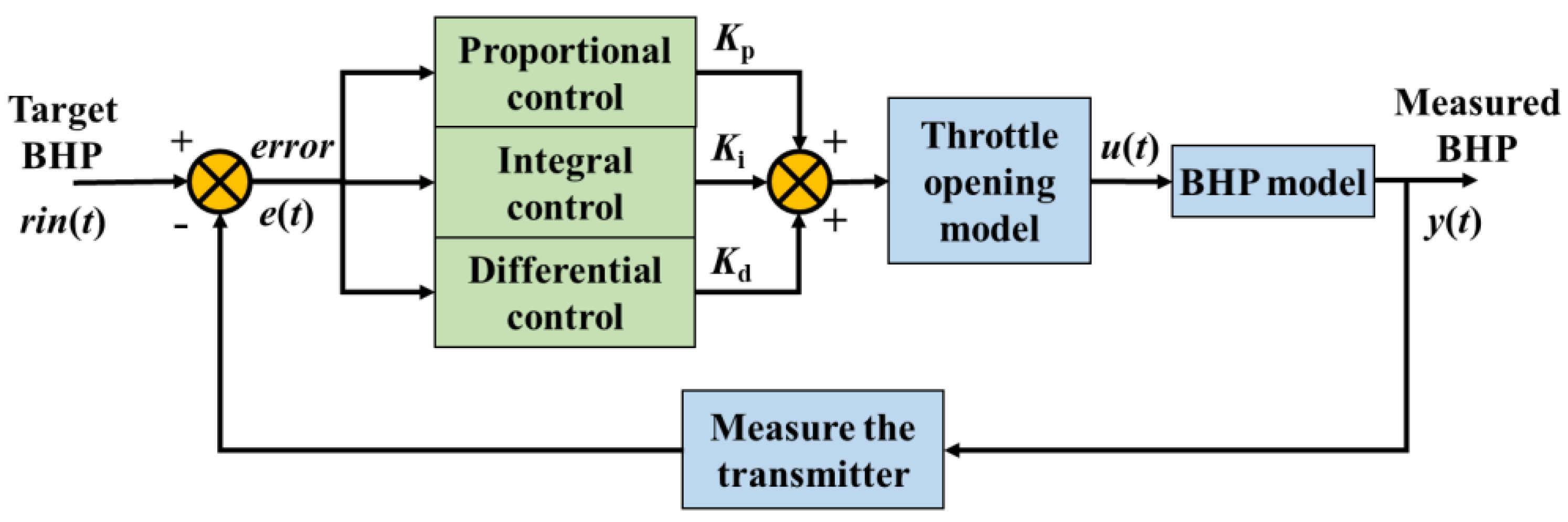
The classic PID controller is still a key technology in many industrial control fields because of its good stability, high reliability, simple structure, and convenient control. The PID controller mainly includes three control modules: proportional, integral, and differential, as shown in Figure 3.
① The proportional part can quickly adjust the control parameters according to the actual deviation of the control target.
② The integral part can evaluate the error of each step of regulation and adjust the control parameters to eliminate the system error.
③ The differential part can control in advance according to the error change ratio and suppress the overshoot effectively.
The PID controller of BHP regulates the opening of the wellhead throttle valve according to the control error (e) between the target of the BHP (rin) and the measured value of the BHP (y) and regulates BHP automatically, where the control error can be expressed as follows:
e t = r i n t y t
First, the automatic regulation control equation for the opening of the wellhead throttle valve is established according to the PID control principle, which is expressed as follows:
u t = K p e t + K i 0 t e t d t + K d d e t d t
where u is the control variable for throttle opening; e is the control error, which is the difference between the target BHP and the actual measured BHP; K p is the proportionality parameter; K i is the integral parameter; and K d is the differential parameter.
The real-time opening of the throttle is shown below:
u t = u t 1 + K p e t + K i t = 0 t e t + K d e t e t 1
The pressure drop caused by the gas–liquid–solid three-phase in the annulus through the wellhead throttle is calculated by the following equation:
Q = C v U max P top P S , 0 x L - S / ρ L - S , top + x G / Y ρ G , top
where Q is the total mass flow rate through the wellhead throttle in k g / s ; C v is the fixed constant of the wellhead throttle valve; U is the wellhead throttle opening; P t o p is the pressure at the wellhead throttle in P a ; P S is the pressure at the downstream end of the wellhead throttle in P a ; x L S is the mass flow fraction of the liquid–solid mixture in k g / m 3 ; x G is the mass flow fraction of the gas phase; ρ L S , t o p is the density of the liquid–solid mixture at the wellhead in k g / m 3 ; ρ G , t o p is the density of the gas phase at the wellhead in k g / m 3 ; and Y is the gas expansion factor.
Therefore, the correspondence between throttle opening and throttle pressure can be obtained by solving Equation (14), and the correspondence between the throttle opening and BHP can be established so that the BHP can be controlled by adjusting throttle opening, and then the gas invasion accident can be handled.
After specifying the target parameters and the control object, this paper searches for the tuning parameters of the PID controller by the grid search method, including K p , K i , and K d , and the search range and step size are shown in Table 4.
Different combinations of regulation parameters were evaluated according to the regulation efficiency and overshoot, and it was found that when K p = 4.00 , K i = 0.02 , and K d = 3.00 , the PID controller of BHP had the highest regulation efficiency and almost zero overshoot, so this combination was selected as the result of the adjustment of the bottom hole pressure PID controller parameters.
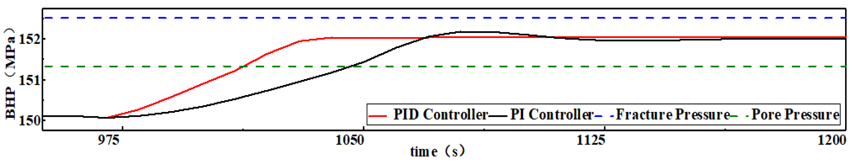
As shown in Figure 4, the PID controller of BHP established in this section has a significantly higher regulation efficiency compared to the existing PI controller of BHP. Because of the addition of the differential control part, the overshoot of the BHP disappears, which makes the BHP regulation process more stable and more reliable.
The pool level reached the warning value 960 s after the gas invasion occurred. The PID controller and PI controller started to regulate the BHP at the same time. The PI controller regulated the BHP within the safety pressure window after 87 s, while the PID controller only took 53 s to regulate the BHP within the safety pressure window, which was 39% more efficient. On the other hand, the PI controller takes 110 s to regulate the BHP to the target BHP, while the PID controller takes only 73 s, saving 34% of the regulation time. During the entire BHP control process, the root mean square error (RMSE) of the PI controller is 0.31 MPa, and the integral absolute error (IAE) is 3250.39 MPa·s. The RMSE of the PID controller is 0.24 MPa, and the IAE is 1870.05 MPa·s. According to the control principle of the PID controller, the function of the differential partial override control and suppression of overshoot is the main reason for the efficiency improvement and the disappearance of the overshoot.

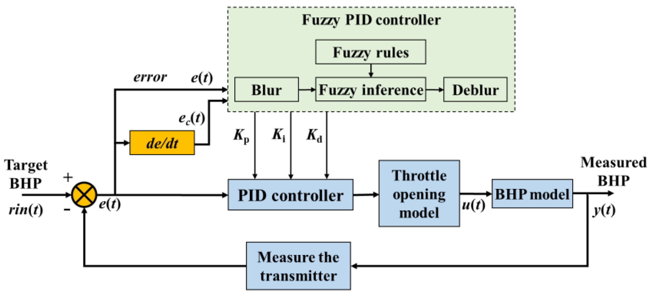
3.3. Fuzzy PID Controller

The fuzzy PID controller couples the fuzzy reasoning and the PID controller. It is the adaptive tuning of the control parameters by establishing the membership function of the control parameters, error, and error change ratio and designing the fuzzy control rules. The fuzzy PID controller can adjust the control parameters dynamically, overcome the limitation of fixed parameters in the PID controller, and improve the control efficiency.
The core of a fuzzy PID controller is a fuzzy inference machine, which can develop reasonable control rules based on human expert experience and includes three stages, such as fuzzification of the control object, fuzzy inference process, defuzzification of the control parameters, etc. The error and the error change ratio are the input of the model, and the control parameters of PID can be adjusted adaptively by fuzzy control rules. Its robustness will be significant compared with classical PID controllers. In this paper, by coupling the fuzzy inference and PID controller, an intelligent regulation model of BHP based on the fuzzy PID controller is developed, and its control principle is shown in Figure 5.
(1) Parameter fuzzification
Firstly, the input parameters are fuzzified. The error e t and error change ratio e c t are two input parameters of the fuzzy PID controller. After parameter fuzzification, fuzzy inference, and defuzzification, the control parameters of PID   K p , K i , and   K d are obtained. One of the parameters’ fuzzification processes is to calculate the fuzzy quantity of the input parameter based on the actual domain [ x L ,    x H ] and its corresponding set domain [−b, b] of the fuzzy quantity ( x ^ ), and the calculation process is as follows:
x ^ = k x x H x L 2
where x ^ is determined by rounding to the nearest whole number, and k is the quantification factor, which is calculated as follows:
k = 2 b x H x L
Based on the actual condition, it was determined that the domains of the two input parameters e and   e c were [−3, −2, −1, 0, 1, 2, 3]. The control domains of the three output parameters K p , K i , and   K d were [−3, −2, −1, 0, 1, 2, 3], [0.020, 0.013, 0.007, 0, 0.007, 0.013, 0.020], and [−3, −2, −1, 0, 1, 2, 3].
The discrete theoretical domain of each parameter corresponds to the following fuzzy geometry {PB, PM, PS, ZE, NS, NM, NB}.
Each parameter corresponds to a fuzzy quantity, and its degree of membership to this fuzzy quantity is calculated by the membership function.
ω B x = 0 0 , 1 1 x   is   not   a   member   of   B   at   all x   is   part   of   B x   is   a   complete   member   of   B
where x is the element; B is the set; and ω B is the membership degree of element x in set B .
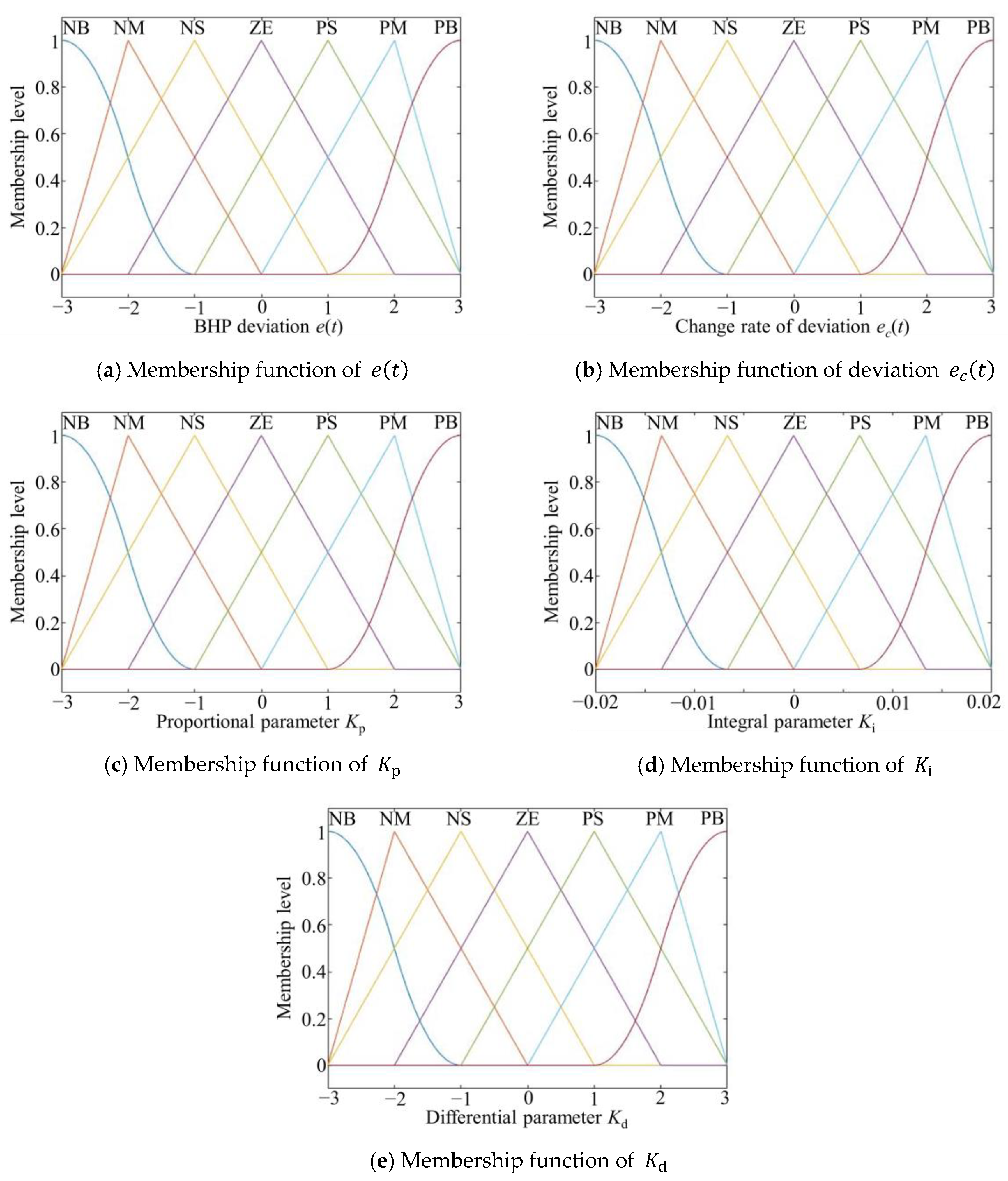
In this paper, triangular, bell-shaped, and sigmoid-type membership functions are used to calculate the membership of the input parameters to the fuzzy quantities. The triangular membership function is as follows:
ω x = 0 , x a t x a t b t a t , a t x b t c t x c t b t , b t x c t 0 , c t x
where a t is the left foot; b t is the peak; and c t is the right foot.
The bell-shaped membership function is as follows:
ω x = 1 1 + x c b a b 2 b b
where a b is the parameter that controls the width of the function; b b is the parameter that indicates the degree of steepness of the slope of the control function; and c b is the center position of the function.
The sigmoid-type membership function is as follows:
ω x = 1 1 + e a s x c s
where a s is the parameter for controlling the slope of the curve; and c s is the center point of the S-shaped curve.
The error e t , error change ratio   e c t , and control parameters   K p ,   K i , and K d of the membership function are shown in Figure 6.
(2) Fuzzy rules and fuzzy inference
Analyzing the response mechanism of BHP to the wellhead choke valve opening and considering the adjustment effect of K p , K i , and K d on the opening degree of the wellhead choke valve and the relationship between them. A fuzzy control rule table for adjusting the K p , K i , and K d changes corresponding to the error and the error change ratio is established. The fuzzy control rule table for regulation is shown in Table 5, Table 6 and Table 7. According to the fuzzy rule table of PID control parameters, it can be self-adaptive tuning according to the real-time deviation and deviation change rate of K p , K i , and K d , which overcomes the limitation of fixed classical PID control parameters and improves the responsiveness and adaptability of the fuzzy PID controller significantly.
(3) Defuzzification
The input parameters are still fuzzy vectors after the fuzzy rule inference operation; it is necessary to deblur them to obtain the exact values of the three control parameter variations. Commonly used defuzzification methods are the maximum membership method, area center method, weighted average method, median method, etc. In this paper, the area center method is used for defuzzification, and the center of gravity of the area enclosed by the membership function curve is used as the final output value. This method is more sensitive to the input signal; even if the input value changes slightly, the output value can make a corresponding change, and the calculation formula is as follows:
x 0 = X x ω x x d x X ω x x d x
where X is the input signal x of the theoretical domain of the input signal.
After calculating the parameter changes of the PID controller based on the area center method, K p , K i , and K d in the PID controller are determined as follows:
K p = K p _ initial + Δ K p K i = K i _ initial + Δ K i K d = K d _ initial + Δ K d
where K p _ i n i t i a l , K i _ i n i t i a l , and K d _ i n i t i a l are the initial parameters’ fuzzy values.
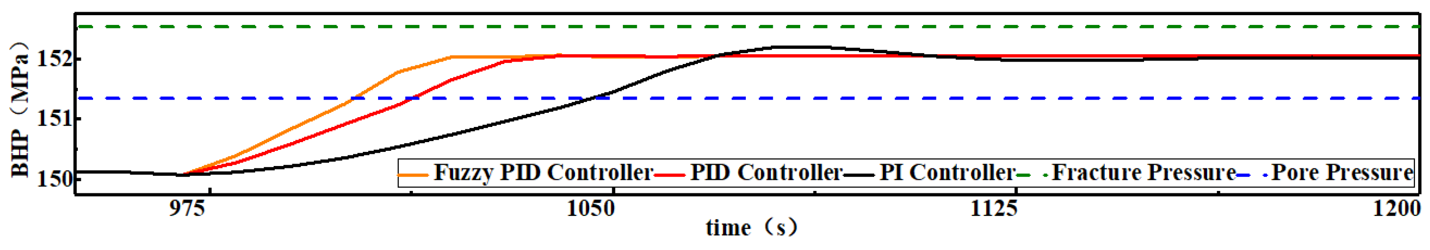
As shown in Figure 7, compared with the traditional PID controller, the response speed of the fuzzy PID control is faster and reduces from 53 s to 42 s, so the fuzzy adaptive PID control suppresses the gas invasion accident 11 s earlier, and its RMSE is 0.22 MPa and IAE is 1674.84 MPa·s. In addition, the time taken by the fuzzy adaptive PID and the traditional PID to regulate the BHP to the target value is 60 s and 73 s, respectively; it can be considered that the regulation efficiency of the fuzzy adaptive PID is improved by about 18% relative to the PID controller, with no overshoot.

3.4. Fuzzy Neural Network PID Controller

The fuzzy neural network PID controller introduces an artificial neural network into the fuzzy control process and uses a multi-layer neural network to realize fuzzy reasoning and optimize fuzzy control rules online in the control process [38]. The fuzzy neural network PID controller takes into account the advantages of fuzzy reasoning and ANN, which not only has good logical reasoning ability but also can realize the dynamic optimization of control rules.
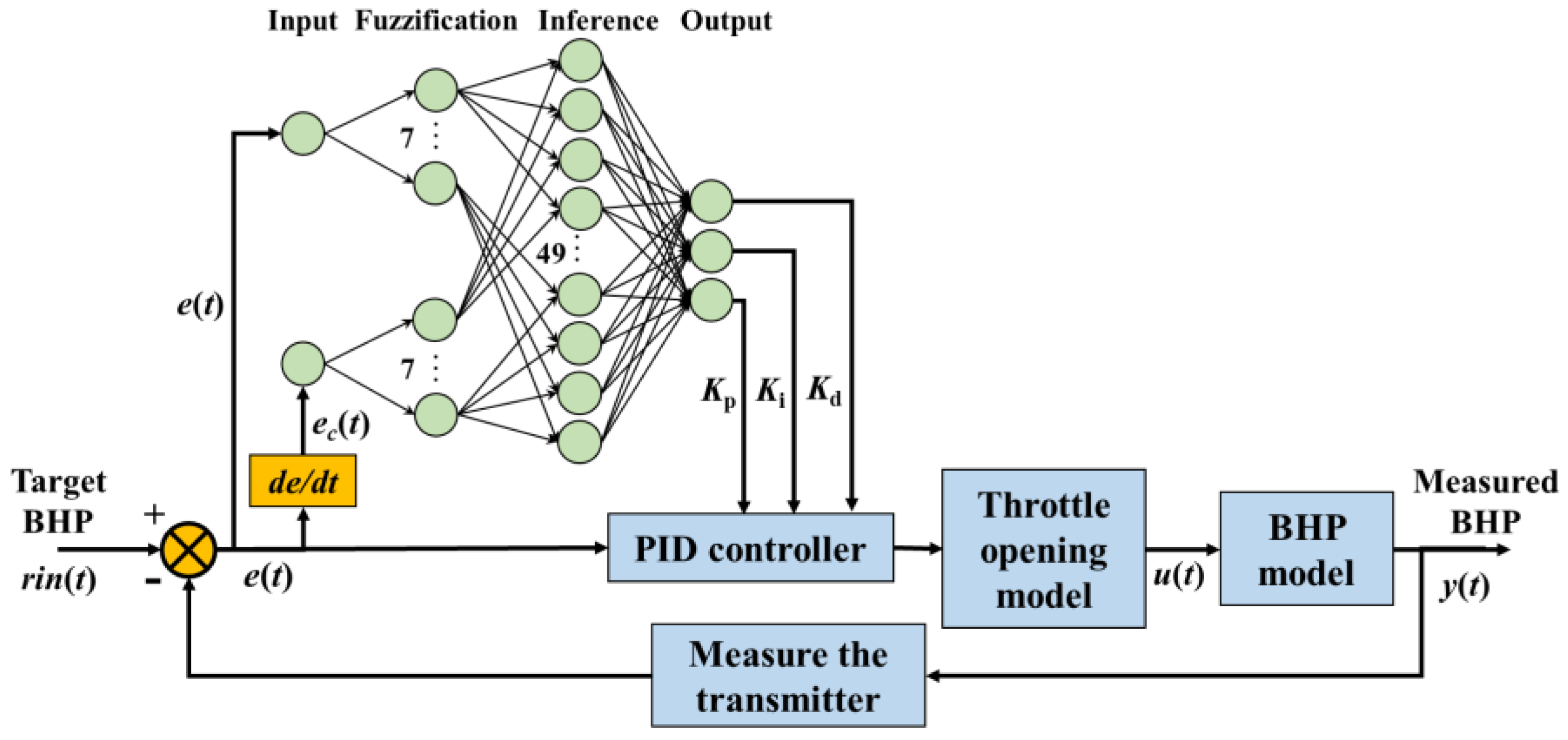
As shown in Figure 8, the fuzzy neural network PID controller is a four-layer neural network that replaces the parameter input, fuzzification, fuzzy inference, and defuzzification processes of the fuzzy PID controller, which not only fully retains the logic inference capability of the fuzzy PID controller but also can overcome the limitation that the neural network PID controller can easily fall into the local optimum, and, at the same time, because the neural network has a strong online learning capability, the fuzzy control rules can be adjusted online to make up for the deficiency in the responsiveness of the controller due to the fixed and unchanging fuzzy control rules. In this paper, based on the fuzzy PID controller established in Section 3.3, a neural network module is introduced to establish a fuzzy neural network PID controller for wellbore pressure.
The input layer of the fuzzy neural network consists of two neurons for e t and e c t of the inputs, which are transmitted to the fuzzification layer in the form of a vector with one row and two columns. The fuzzification layer includes 14 neuron nodes, and the two output signals of the input layer are transmitted to 7 neuron nodes, each of which acts as the equivalent of a membership function to divide the theoretical domain of the input values into seven fuzzy intervals of the fuzzy quantity domain, P B , P M , P S , Z E , N S , N M , N B ; the output signal of the input layer is passed to the fuzzy inference layer in the form of a membership matrix with two rows and seven columns after being calculated by the membership function. There are 49 neuron nodes in the fuzzy inference layer, and each node corresponds to a fuzzy rule. The input signal is fuzzed by the fuzzification layer and then logically reasoned using the fuzzy rule function, and the fuzzy matrix obtained by the inference is passed to the output layer. The three neurons in the output layer will obtain the change of control parameters of the PID controller by weighting the fuzzy quantity output from the fuzzy inference layer after the weighting operation K p , K i , and K d , which is the defuzzification process.
After determining the fuzzy neural network structure, the solution of the fuzzy neural network PID controller for the BHP is achieved by the following process:
(1) Random initialization of the neural network weight matrix.
(2) Input the present value of the BHP error and the amount of error variation into the neural network.
(3) The input parameters are transmitted through the neural network to output the wellbore pressure regulation parameters K p , K i , and K d .
(4) After the controller calculates the control volume of the wellhead throttle, the output value of the BHP is obtained after the calculation of the three-phase flow model in the annulus.
(5) Calculation of the error and the rate of change of the error in the target and output values of the BHP.
(6) Backpropagation of the neural network module to compute the partial derivatives of the objective function for the parameter matrix.
(7) Adjustment of the weight matrix according to the fastest decreasing direction of the objective function and the established learning rate of the neural network.
(8) Cycle steps 2–7 until the wellbore pressure is regulated to the target value.
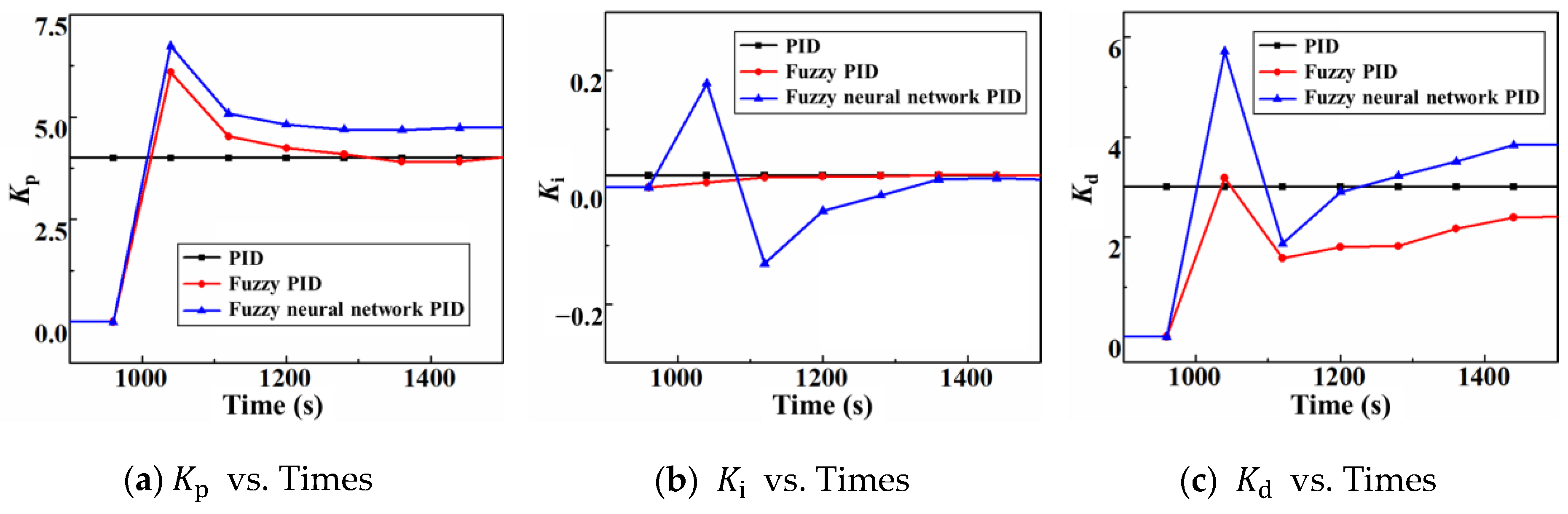
Based on the above model construction and solution methods, a fuzzy neural network PID control model for the BHP is constructed. As shown in 
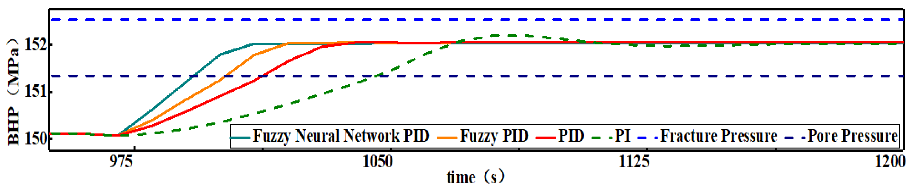
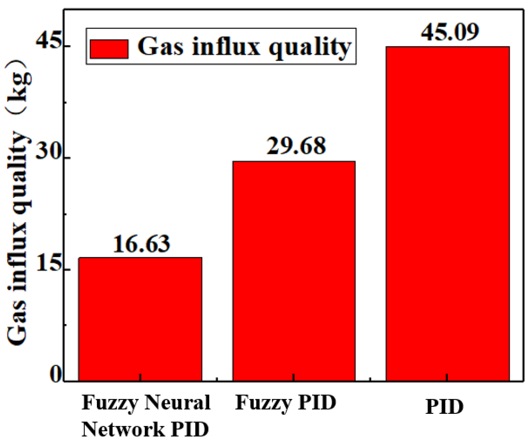
Figure 9, the efficiency of the fuzzy neural network PID controller is further improved for the fuzzy PID controller in terms of BHP regulation. The fuzzy neural network PID controller starts regulating the BHP from 960 s and takes only 32 s to regulate BHP within the safety pressure window, which is 10 s earlier compared to the fuzzy PID controller; the efficiency is improved by 24%, the RMSE is only 0.20 MPa, and the IAE is only 1487.58 MPa·s. On the other hand, the fuzzy neural network PID controller regulates BHP to the target value at 1010 s with no overshoot, which is 10 s earlier compared to the fuzzy PID controller and has a 17% efficiency improvement. The further improvement of the fuzzy neural network PID regulation performance is due to its ability to achieve adaptive tuning of the control parameters and online optimization of the control rules through fuzzy control rules and neural network modules simultaneously.
The time and error comparison of the four controllers to control the BHP to the target value is shown in Table 8. It can be seen that the fuzzy neural network PID takes the least time, has the lowest error, and has good BHP control performance.

4. Comparison and Discussion

This section compares and analyzes the performance of different intelligent controllers in terms of control parameters, throttle pressure, gas invasion mass flow rate, and gas invasion volume of BHP regulation and gas invasion handling.

4.1. Control Parameters Comparison

Figure 10 shows the variation of K p , K i , and K d with time for three BHP control models in dealing with the gas invasion. In the PID control model, the control parameters K p , K i , and K d must be set with extensive experience before BHP regulation, and they cannot be tuned adaptively and cannot vary with the control time. In the fuzzy PID and fuzzy neural network PID, the control parameters K p , K i , and K d can be tuned adaptively and have an obvious variation. Among them, the fuzzy neural network PID can further optimize the control rules by the neural network module; this can improve the response performance of the control parameters compared with the fuzzy PID controller.

4.2. Throttle Pressure Comparison

Figure 11 shows the variation in throttle pressure with time for three BHP control models in dealing with the gas invasion. At 960 s, a gas invasion warning is issued, and all three controls start regulating the wellbore pressure simultaneously. The PID controller model took a total of 400 s from the start of the gas invasion warning to the end of the gas invasion treatment, and the fuzzy PID control model took a total of 320 s from the gas invasion warning to the end of the gas invasion treatment, while the fuzzy neural network PID control model took only 240 s to handle the gas invasion, which improved the regulation efficiency by 40% over the PID control model and 25% over the fuzzy PID control model. Therefore, the fuzzy neural network PID can regulate the throttle valve opening and pressure more efficiently, thus increasing the BHP and reducing the gas invasion rate in a short time until the well is successfully pressurized.

4.3. Mass Flow Rate of Gas Kick Comparing

Figure 12 compares the variation in gas invasion mass flow rates in the annulus with time for the three models of smart regulation of BHP in dealing with the gas invasion. Due to the low efficiency of throttle pressure regulation, the gas invasion flow rate under the PID control treatment is at the highest level after the measures are taken, increasing the fluctuation of the BHP and the difficulty of regulation in the later period.
In contrast, the fuzzy PID controller and the fuzzy neural network PID controller, which combines a fuzzy inference machine and a fuzzy neural network, are more efficient in controlling the gas invasion flow rate, which can be reduced at a higher rate since the start of regulation, avoiding more gas invasion and larger fluctuations in BHP. This is because the fuzzy neural network PID control can regulate the pressure at the wellhead throttle more efficiently, thus suppressing gas invasion.

4.4. Gas Influx Quality Comparing

As shown in Figure 13, for the same gas invasion conditions, the gas invasion mass during the regulation of the BHP by the fuzzy neural network PID controller is 16.63 kg, while the gas invasion mass generated during the regulation by the fuzzy PID controller and the classical PID controller is 29.68 kg and 45.09 kg, respectively. It can be seen that because the fuzzy neural network PID controller can efficiently regulate the BHP, thus effectively suppressing the rate of gas invasion, its ability to handle gas invasion is improved by 63% compared to the classical PID controller. Therefore, the fuzzy neural network PID controller can more effectively suppress the growth of pool level and fluctuation of BHP when dealing with gas invasion, and its ability to deal with gas invasion incidents under the same conditions is significantly improved.

5. Conclusions

Based on the circulating gas–liquid–solid three-phase flow heat transfer model, established under high-temperature and high-pressure drilling gas invasion conditions in deep wells, a PID controller for BHP was established in combination with automatic control theory to realize the automatic regulation and control of wellbore pressure. Based on this, fuzzy control rules were introduced to realize the adaptive rectification of PID control parameters to establish a fuzzy PID controller for BHP, and the introduction of a neural network module, combined with the online learning capability of the neural network, establishes the fuzzy neural network PID controller for BHP. Finally, the performance of three different controllers in BHP control and gas invasion treatment is compared and analyzed, and the following conclusions are drawn:
(1) As the core scientific contribution of this study, the introduction of a fuzzy inference machine and the construction of a fuzzy neural network module to achieve adaptive tuning of PID control parameters and online optimization of fuzzy control rules effectively improves the efficiency and responsiveness of the downhole pressure controller. Moreover, due to the online optimization of control rules, the generalization capability of the fuzzy neural network PID controller for different control systems of the BHP is significantly improved.
(2) The BHP fuzzy neural network PID controller can adjust the control parameters and control rules according to the real-time changes of the annular multiphase flow system and the BHP control deviation, so the efficiency of BHP regulation is significantly improved compared with the classical PID control. In this case, the classical PID controller takes 53 s to regulate the BHP within the safety pressure window, while the fuzzy neural network PID controller takes only 32 s, which is 38% more efficient. Meanwhile, the classical PID controller takes 73 s to regulate the BHP to the target pressure, while the fuzzy neural network PID controller takes only 50 s, which is 32% more efficient.
(3) Since the BHP fuzzy neural network PID controller can adjust the wellhead throttle opening and BHP more quickly, it can suppress the gas invasion rate more efficiently and reduce the total gas invasion and BHP fluctuation, which effectively improves its ability to handle gas invasion. In this case, the total amount of gas invasion during a gas invasion treatment by the fuzzy neural network PID controller was 16.63 kg, and the total amount of gas invasion during a gas invasion treatment by the classical PID controller was 45.09 kg, compared with the 63% improvement in the treatment capability of gas invasion by the fuzzy neural network PID controller for the BHP.
Despite the promising results, some limitations of the current study should be acknowledged and will guide future work. Firstly, the integration of the FNN-PID controller with a detailed non-isothermal three-phase transient model introduces a significant computational load, which may limit real-time applicability. Future work will consider the development of reduced-order models or surrogate-assisted control strategies to improve the computational efficiency. Secondly, the current model assumes a vertical wellbore geometry and fixed drilling conditions; extending the model to complex well types, such as deviated or horizontal wells, will be essential for broader applicability. Lastly, while this study is based on simulation data, integrating the proposed control framework with real-time field data (e.g., from pressure-while-drilling or temperature sensors) is a promising direction for enabling intelligent, adaptive BHP management in real-world drilling environments.

Author Contributions

Conceptualization, Y.Z. and Z.Z.; methodology, Y.Z. and X.Y.; software, X.Y.; validation, X.Y. and W.Z.; formal analysis, Y.Z.; investigation, X.Y. and W.Z.; resources, Z.Z.; data curation, Y.Z. and X.Y.; writing—original draft preparation, Y.Z.; writing—review and editing, Y.Z., X.Y. and W.Z.; visualization, W.Z.; supervision, W.Z. and Z.Z.; project administration, Z.Z. All authors have read and agreed to the published version of the manuscript.

Funding

This research was funded by the Youth Foundation of the National Natural Science Foundation of China grant number 52204020 and the National Key Research and Development Program grant number 2019YFA0708300.

Institutional Review Board Statement

Not applicable.

Informed Consent Statement

Not applicable.

Data Availability Statement

The raw data supporting the conclusions of this article will be made available by the authors on request.

Conflicts of Interest

Author Yuqiang Zhang was employed by the Jianghan Oilfield company and author Wenping Zhang was employed by the Sinopec Petroleum Engineering Technology Research Institute Co., Ltd. The remaining authors declare that the research was conducted in the absence of any commercial or financial rela-tionships that could be construed as a potential conflict of interest.

References

  1. Liang, H.; Liu, G.; Zou, J.; Bai, J.; Jiang, Y. Research on calculation model of bottom of the well pressure based on machine learning. Future Gener. Comput. Syst. 2021, 124, 80–90. [Google Scholar] [CrossRef]
  2. Yin, H.; Liu, P.; Li, Q.; Wang, Q.; Gao, D. A new approach to risk control of gas kick in high-pressure sour gas wells. J. Nat. Gas Sci. Eng. 2015, 26, 142–148. [Google Scholar] [CrossRef]
  3. Wang, J.; Deng, S.; Li, J.; Yang, H.; Liu, G. Development of a multiphase variable mass flow model and its application in well control for variable gradient managed pressure drilling. Energy Rep. 2023, 9, 3358–3368. [Google Scholar] [CrossRef]
  4. Hannegan, D.; Todd, R.J.; Pritchard, D.M.; Jonasson, B. MPD—Uniquely Applicable to Methane Hydrate Drilling. In Proceedings of the SPE/IADC Underbalanced Technology Conference and Exhibition, Houston, TX, USA, 11–12 October 2004. [Google Scholar]
  5. Kaasa, G.-O.; Stamnes, Ø.N.; Imsland, L.; Aamo, O.M. Simplified Hydraulics Model Used for Intelligent Estimation of Downhole Pressure for a Managed-Pressure-Drilling Control System. SPE Drill. Complet. 2012, 27, 127–138. [Google Scholar] [CrossRef]
  6. Chen, X.; He, M.; Xu, M.; Wang, S.; Dai, B. Early gas kick detection-inversion-control integrated system: The significance of applications of managed pressure drilling: A review. Geoenergy Sci. Eng. 2023, 229, 212134. [Google Scholar] [CrossRef]
  7. Pozo, M.; Torres, F.; Bedoya, J.; Leroy, J.C.; Montilva, J. Enhancing Performance and Operational Safety of Argentinean Vaca Muerta Shale Wells by Drilling High Pressure Formations Using Managed Pressure Drilling. In Proceedings of the SPE Annual Technical Conference and Exhibition, San Antonio, TX, USA, 9–11 October 2017. [Google Scholar]
  8. Vega, M.P.; Freitas, M.G.; Folsta, M.G.; Gandelman, R.A.; Martins, A.L. Experimental Control of Annulus Pressure While Drilling Oil Wells. IFAC Proc. Vol. 2012, 45, 134–139. [Google Scholar] [CrossRef]
  9. van Riet, E.J.; Reitsma, D.; Vandecraen, B. Development and Testing of a Fully Automated System to Accurately Control Downhole Pressure During Drilling Operations. In Proceedings of the SPE/IADC Middle East Drilling Technology Conference and Exhibition, Abu Dhabi, United Arab Emirates, 20–22 October 2003. [Google Scholar]
  10. Pedersen, T.; Godhavn, J.-M. Model Predictive Control of Flow and Pressure in Underbalanced Drilling. IFAC Proc. Vol. 2013, 46, 307–312. [Google Scholar] [CrossRef]
  11. Nandan, A.; Imtiaz, S. Nonlinear model predictive control of managed pressure drilling. ISA Trans. 2017, 69, 307–314. [Google Scholar] [CrossRef]
  12. Nandan, A.; Imtiaz, S. Nonlinear Model Predictive Controller for Kick Attenuation in Managed Pressure Drilling. IFAC-Pap. 2016, 49, 248–253. [Google Scholar] [CrossRef]
  13. Nygaard, G.H.; Imsland, L.S.; Johannessen, E.A. Using NMPC Based on A Low-Order Model for Controlling Pressure During Oil Well Drilling. IFAC Proc. Vol. 2007, 40, 159–164. [Google Scholar] [CrossRef]
  14. Sule, I.; Imtiaz, S.; Khan, F.; Butt, S. Nonlinear model predictive control of gas kick in a managed pressure drilling system. J. Pet. Sci. Eng. 2019, 174, 1223–1235. [Google Scholar] [CrossRef]
  15. Sule, I.; Imtiaz, S.; Khan, F.; Butt, S. Risk analysis of well blowout scenarios during managed pressure drilling operation. J. Pet. Sci. Eng. 2019, 182, 106296. [Google Scholar] [CrossRef]
  16. Li, Z.; Hovakimyan, N.; Kaasa, G.-O. Bottomhole Pressure Estimation and 1 Adaptive Control in Managed Pressure Drilling System. IFAC Proc. Vol. 2012, 45, 128–133. [Google Scholar] [CrossRef]
  17. Mahdianfar, H.; Hovakimyan, N.; Pavlov, A.; Aamo, O.M. L1 adaptive output regulator design with application to Managed Pressure Drilling. J. Process Control 2016, 42, 1–13. [Google Scholar] [CrossRef]
  18. Li, Q.; Kamel, M. Robustness Analysis and Tuning for Pressure Control in Managed Pressure Drilling. IFAC-Pap. 2016, 49, 556–561. [Google Scholar] [CrossRef]
  19. Mahdianfar, H.; Morten Aamo, O.; Pavlov, A. Suppression of Heave-Induced Pressure Fluctuations in MPD. IFAC Proc. Vol. 2012, 45, 239–244. [Google Scholar] [CrossRef]
  20. Nandan, A.; Imtiaz, S.; Butt, S. Robust gain switching control of constant bottomhole pressure drilling. J. Process Control 2017, 57, 38–49. [Google Scholar] [CrossRef]
  21. Sule, I.; Khan, F.; Butt, S.; Yang, M. Kick control reliability analysis of managed pressure drilling operation. J. Loss Prev. Process Ind. 2018, 52, 7–20. [Google Scholar] [CrossRef]
  22. Sheikhi, M.A.; Nikoofard, A.; Khaki-Sedigh, A. Control of managed pressure drilling systems using nonlinear predictive generalized minimum variance approach based on a Volterra model. ISA Trans. 2022, 128, 380–390. [Google Scholar] [CrossRef]
  23. Naderi Lordejani, S.; Besselink, B.; Schilders, W.H.A.; van de Wouw, N. Model complexity reduction and controller design for managed pressure drilling automation. J. Process Control 2023, 122, 69–83. [Google Scholar] [CrossRef]
  24. Wang, G.; Lv, Z.; Zhong, L.; Li, Z.; Fu, Q.; Li, Y.; He, Y.; Liu, H. Hydraulic modeling study and control algorithm design of double-layer pipe dual-gradient drilling. Geoenergy Sci. Eng. 2024, 240, 212926. [Google Scholar] [CrossRef]
  25. Zhou, J. Adaptive PI Control of Bottom Hole Pressure during Oil Well Drilling. IFAC-Pap. 2018, 51, 166–171. [Google Scholar] [CrossRef]
  26. Zhou, J.; Gravdal, J.E.; Strand, P.; Hovland, S. Automated Kick Control Procedure for an Influx in Managed Pressure Drilling Operations. Model. Identif. Control Nor. Res. Bull. 2016, 37, 31–40. [Google Scholar] [CrossRef]
  27. Zhou, J.; Krstic, M. Adaptive predictor control for stabilizing pressure in a managed pressure drilling system under time-delay. J. Process Control 2016, 40, 106–118. [Google Scholar] [CrossRef]
  28. Zhou, J.; Nygaard, G. Control and estimation of downhole pressure in managed pressure drilling operations. In Proceedings of the 2010 4th International Symposium on Communications, Control and Signal Processing (ISCCSP), Limassol, Cyprus, 3–5 March 2010; IEEE: Piscataway, NJ, USA, 2010; pp. 1–6. [Google Scholar]
  29. Erge, O.; Gu, Q.; Chen, D.; van Oort, E. MPD choke control considering the thixotropic gelation behavior of drilling fluids. J. Pet. Sci. Eng. 2022, 208, 109793. [Google Scholar] [CrossRef]
  30. Godhavn, J.-M. Control Requirements for High-End Automatic MPD Operations. In Proceedings of the SPE/IADC Drilling Conference and Exhibition, Amsterdam, The Netherlands, 17–19 March 2009. [Google Scholar]
  31. Siahaan, H.B.; Jin, H.; Safonov, M.G. An Adaptive PID Switching Controller for Pressure Regulation in Drilling. IFAC Proc. Vol. 2012, 45, 90–94. [Google Scholar] [CrossRef]
  32. Vega, M.P.; de Moraes Oliveira, G.F.; Fernandes, L.D.; Martins, A.L. Monitoring and control strategies to manage pressure fluctuations during oil well drilling. J. Pet. Sci. Eng. 2018, 166, 337–349. [Google Scholar] [CrossRef]
  33. Zhang, H.; Qiu, Y.; Liang, H.; Li, Y.; Yuan, X. Research on remote intelligent control technology of throttling and back pressure in managed pressure drilling. Petroleum 2021, 7, 222–229. [Google Scholar] [CrossRef]
  34. Gorjizadeh, H.; Ghalehnoie, M.; Negahban, S.; Nikoofard, A. Fuzzy controller design for constant bottomhole pressure drilling under operational/physical constraints. J. Pet. Sci. Eng. 2022, 212, 110335. [Google Scholar] [CrossRef]
  35. Patrício, R.V.; Oliveira, G.d.M.; Dalbone de Carvalho, M.A.; Martins, A.L.; Fernandes, L.D.; Vega, M.P. Dynamic gas kick regulation through control reconfiguration under MPD scenario—Two-phase flow validation. J. Pet. Sci. Eng. 2019, 172, 806–818. [Google Scholar] [CrossRef]
  36. Yang, H.-W.; Li, J.; Jiang, J.-W.; Zhang, H.; Guo, B.-Y.; Zhang, G.; Chen, W. A dynamic managed pressure well-control method for rapid treatment of gas kick in deepwater managed pressure drilling. Pet. Sci. 2022, 19, 2297–2313. [Google Scholar] [CrossRef]
  37. Kim, J.; Cho, M.-K.; Jung, M.; Kim, J.; Yoon, Y.-S. Rotary hearth furnace for steel solid waste recycling: Mathematical modeling and surrogate-based optimization using industrial-scale yearly operational data. Chem. Eng. J. 2023, 464, 142619. [Google Scholar] [CrossRef]
  38. Yang, R.; Gao, Y.; Wang, H.; Ni, X. Fuzzy Neural Network PID Control Used in Individual Blade Control. Aerospace 2023, 10, 623. [Google Scholar] [CrossRef]
Figure 1. Flow chart of the solution procedure.
Applsci 15 07256 g001
Figure 2. Comparison results of the proposed model with Drillbench and measured data.
Applsci 15 07256 g002
Figure 3. BHP regulation model principle based on the PID controller.
Applsci 15 07256 g003
Figure 4. BHP vs. time for the PI controller method and the PID controller method.
Applsci 15 07256 g004
Figure 5. BHP regulation model principle based on the fuzzy PID controller.
Applsci 15 07256 g005
Figure 6. Membership function graph of each parameter.
Applsci 15 07256 g006
Figure 7. BHP vs. time for the PI, PID, and fuzzy PID controllers.
Applsci 15 07256 g007
Figure 8. BHP control model based on the fuzzy neural network PID controller.
Applsci 15 07256 g008
Figure 9. Effects of various intelligent controllers on BHP.
Applsci 15 07256 g009
Figure 10. Control parameter vs. times for PID, fuzzy PID, and fuzzy neural network PID.
Applsci 15 07256 g010
Figure 11. Throttle pressure vs. time for PID, fuzzy PID, and fuzzy neural network PID.
Applsci 15 07256 g011
Figure 12. The mass flow rate of gas kick vs. time under different BHP intelligent control models.
Applsci 15 07256 g012
Figure 13. Gas influx quality vs. time for PID, fuzzy PID, and fuzzy neural network PID controller.
Applsci 15 07256 g013
Table 1. Convection heat transfer coefficient of different flow patterns.
Flow PatternConvection Heat Transfer Coefficient and Its Supplementary EquationParameter Description
Bubble flow h M = N u M λ M 2 r ca 3 , i r dp , o
N u M = f M 2 R e M P r M 1.07 + 12.7 f M 2 P r M 2 / 3 1 μ M μ M , W 1 / 4
R e M = 2 ρ M V M r ca 3 , i r dp , o μ M
P r M = C p M μ M λ M
h is the convection heat transfer coefficient in W / m 2 / ° C ; λ is the thermal conductivity in W / m / ° C ; N u is the Nusselt number; C p is the specific heat capacity in J / k g / ° C ; f is the friction factor; R e is the Reynolds number; P r is the Prandtl number; μ is the viscosity in P a · s ; and subscript M is the mixture.
Diffuse bubble flow
Mixing flow
Slug flow h M = h TB χ + h LS 1 χ
h TB = 2.08 α L 2 / 3 h LTB
h LS = N u LS 2 r ca 3 , i r dp , o λ LS
N u LS = f 2 R e LS P r LS 1.07 + 12.7 f 2 P r LS 2 / 3 1 μ LS μ LS , W 1 / 4
Subscripts TB and LS are the Taylor bubble region and liquid slug region, respectively.
Subscript LTB is the Taylor bubble zone liquid film.
Table 2. Basic data of the validation well.
ParametersValuesParametersValues
Well depth5318 m Rate of penetration20 m / s
Casing depth4931 m Flow rate23.14 L / s
Casing inner diameter0.2 m Drilling fluid density1100 k g / m 3
Bit diameter0.1683 m Drilling fluid viscosity17 m P a · s
Drill pipe outer diameter0.127 m Inlet temperature10 °C
Drill pipe inner diameter0.1086 m Surface temperature20 °C
Drill bit nozzle diameter3 × 0.3142 m Geothermal gradient0.02 °C/m
Cutting density2650 k g / m 3 String density7800 k g / m 3
Cutting specific heat capacity837 J / k g · String specific heat capacity400 J / k g ·
Cutting thermal conductivity2.25 W / m · String thermal conductivity43.75 W / m ·
Table 3. Basic data of the simulated well.
ParametersValuesParametersValues
Vertical Depth8000 m Drill pipe inner diameter0.0943 m
Drill pipe outer diameter0.1143 m Borehole diameter0.1651 m
Liquid-phase flow rate26.25 k g / s High-pressure gas permeability15/30/45 m D
Gas layer drilling open thickness5 m The radius of gas invasion supply150 m
Drilling fluid injection temperature20 °CGeothermal gradient0.02 °C/m
Rate of penetration2 m / h Rock chip equivalent diameter0.005 m
Drilling fluid viscosity0.07 P a · s The roughness of the ring’s hollow wall surface25.4 × 10−6 m
Stratigraphic rock density2650 k g / m 3 Drilling fluid density1750 k g / m 3
Initial bottom hole differential pressure2 M P a Pool level increment warning value2.5 m 3
Table 4. PID control grid search in the parameter setting process.
Search ParametersSearch ScopesSearch StepsOptimization Results
K p 1.00~8.000.504.00
K i 0~0.060.010.02
K d 0~6.000.503.00
Table 5. Fuzzy rule table of proportional parameter variation K p .
ec(t)NBNMNSZEPSPMPB
ΔKp
e(t)
NBPBPBPMPMPSZEZE
NMPBPBPMPSPSZENS
NSPMPMPMPSZENSNS
ZEPMPMPSZENSNMNM
PSPSPSZENSNSNMNM
PMPSZENSNMNMNMNB
PBZEZENMNMNMNBNB
Table 6. Fuzzy rule table of the integral parameter variation K i .
ec(t)NBNMNSZEPSPMPB
ΔKi
e(t)
NBNBNBNMNMNSZEZE
NMNBNBNMNSNSZEZE
NSNBNMNSNSZEPSPS
ZENMNMNSZEPSPMPM
PSNMNSZEPSPSPMPB
PMZEZEPSPSPMPBPB
PBZEZEPSPMPMPBPB
Table 7. Fuzzy rule table of the differential parameter variation K d .
ec(t)NBNMNSZEPSPMPB
ΔKd
e(t)
NBPSNSNBNBNBNMPS
NMPSNSNBNMNMNSZE
NSZENSNMNMNSNSZE
ZEZENSNSNSNSNSZE
PSZEZEZEZEZEZEZE
PMPBNSPSPSPSPSPB
PBPBPMPMPMPSPSPB
Table 8. Comparison of the four controllers.
IndicatorsPIPIDFuzzy PIDFuzzy Neural Network PID
Regulation time (s)87534232
RMSE (MPa)0.310.240.220.20
IAE (MPa·s)3250.391870.051674.841487.58
Disclaimer/Publisher’s Note: The statements, opinions and data contained in all publications are solely those of the individual author(s) and contributor(s) and not of MDPI and/or the editor(s). MDPI and/or the editor(s) disclaim responsibility for any injury to people or property resulting from any ideas, methods, instructions or products referred to in the content.

