Article

BDS-PPP-B2b-Based Smartphone Precise Positioning Model Enhanced by Mixed-Frequency Data and Hybrid Weight Function

1
School of Land Science and Technology, China University of Geosciences Beijing, Beijing 100083, China
2
Key Laboratory of Monitoring and Protection of Natural Resources in Mining Cities, Ministry of Natural Resources, Jinzhong 030600, China
*
Author to whom correspondence should be addressed.
Appl. Sci. 2025, 15(13), 7169; https://doi.org/10.3390/app15137169
Submission received: 22 April 2025 / Revised: 17 June 2025 / Accepted: 20 June 2025 / Published: 25 June 2025
(This article belongs to the Special Issue Advanced GNSS Technologies: Measurement, Analysis, and Applications)

Abstract

Compared to high-cost hardware-based Global Navigation Satellite System (GNSS) positioning techniques, smartphone-based precise positioning technology plays an important role in applications such as the Internet of Things (IoT). Since Google released the Nougat version of Android in 2016, this has provided a new method for achieving high-accuracy positioning solutions with a smartphone. However, two factors are limiting smartphone-based high-accuracy applications, namely, real-time precise orbit/clock products without the internet and the quality-adaptive precise point positioning (PPP) model. To overcome these two factors, we introduce BDS PPP-B2b orbit/clock corrections and a hybrid weight function (based on C/N0 and satellite elevation) into smartphone real-time PPP. To validate the performance of such a method, two sets of field tests were arranged to collect the smartphone’s GNSS measurements and PPP-B2b orbit/clock corrections. The results illustrated that the hybrid weight function led to 5.13%, 18.00%, and 15.15% positioning improvements compared to the results of the C/N0-dependent model in the east, north, and vertical components, and it exhibited improvements of 71.10%, 72.53%, and 53.93% compared to the results of the satellite-elevation-angle-dependent model. Moreover, the mixed-frequency measurement PPP model could also provide positioning improvements of about 14.63%, 19.99%, and 9.21%. On average, the presented smartphone PPP model can bring about 76.64% and 59.84% positioning enhancements in the horizontal and vertical components.

1. Introduction

With the rapid development of mobile technology, smartphones with functions of communication, navigation, and entertainment are becoming indispensable tools in daily life. How to provide a positioning service with the characteristics of precision, continuity, and reliability by using smartphones has become a prominent research focus point. Since Google established the Application Programming Interface (API) for decoding raw GNSS observations in the Nougat version of Android in 2016, more attention has been paid to raw Global Navigation Satellite System (GNSS)-measurement-based positioning using smartphones [1,2]. Meanwhile, benefitting from the rapid developments of smartphones and the Internet of Things (IoT), the potential of smartphone-based high-accuracy positioning technology is increasing unprecedentedly. Moreover, the performance of the GNSS chipset embedded in smartphones has gradually been enhanced in terms of tracking multi-frequency multi-constellation signals, decreasing measurement noise, and optimizing the duty cycle mechanism, which has enabled researchers to provide higher-accuracy positioning services by using carrier-phase-measurement-based positioning methods such as precise point positioning (PPP) and real-time kinematic positioning (RTK) [3,4].
However, compared to RTK (which is a typical relative positioning mode), PPP is an absolute positioning mode that does not rely on a base station and is not affected by the baseline length. PPP works by only using the raw measurements from the user station and the precise orbit/clock products [5,6,7,8]. Meanwhile, compared to Standard Point Positioning (SPP), which is based on meter-level pseudo-range and is adopted by almost all smartphones at present [9,10], PPP is based on millimeter-level carrier phase observations. Due to hardware cost and performance limitations, it is almost impossible for PPP in smartphones to achieve millimeter-level positioning using dual-frequency carrier phase observations. However, it is recognized that the positioning accuracy of smartphones can reach the sub-meter or even centimeter level [11,12,13,14]. Therefore, PPP is treated as a potential higher-accuracy positioning method for smartphones. However, the implementation of PPP in smartphones is still limited by some challenges. For example, the antenna of the embedded GNSS chipset is designed to be omnidirectional and linearly polarized, which leads to more severe multipath errors and more frequent cycle slips. As a result, it takes more time for smartphones to converge to a high-accuracy positioning solution [15].
Besides the multipath and cycle slip errors, ionosphere delay is another key issue decreasing the positioning accuracy of smartphones. Usually, dual-frequency GNSS observations are utilized to form an ionosphere-free combination. However, for smartphones, only single-frequency GNSS observations were available before 2018, which made it hard to form an ionosphere-free combination for PPP. Fortunately, smartphones are now currently equipped with dual-frequency GNSS chips. However, even in open-sky observation environments, the number of GNSS satellites that can provide dual-frequency observations is rather low for smartphones [16], compared to the number of GNSS satellites that can provide single-frequency data (L1/B1/G1/E1) [12]. In addition, the integrity of the dual-frequency data (i.e., L1 + L5 and E1 + E5a) in smartphones is much lower than that of single-frequency data (i.e., L1 and E1). This means that the positioning performance using dual-frequency ionosphere-free PPP is difficult to maintain at a high accuracy. This fact results in it being the case that single-frequency PPP is still the most available precise positioning mode for most smartphones. In addition, the inconsistent clocks in the carrier phase and pseudo-range in smartphones resulted in inconsistent pseudo-ranges and carrier phase observations [3]. Such inconsistencies have been resolved by Wang et al. (2021) and Chen et al. (2019) by setting independent receiver clock biases for the pseudo-range and carrier phase in [2,17]. Zanggehnejad et al. (2023) demonstrated that such inconsistencies can also be recovered by adjusting the phase or using only the first value of the FullBiasNanos while generating a pseudo-range [18].
Currently, many studies have been performed to improve the accuracy of smartphones through post-processing models. For example, by using a Hatch-filtering-based carrier-phase-smoothed pseudo-range, the positioning accuracy based on the double-differenced pseudo-range with this carrier phase smoothing technique is less than 5 m [19]. According to the work in [20], the positioning accuracy based on smartphones’ pseudo-ranges can be improved by more than 50% after introducing the velocity-aided constraint. While using the PPP mode, positioning accuracies in the horizontal and vertical components are approximately 0.37 m and 0.51 m [21]. While employing a C/N0 weight function method in the positioning mode based on the fusion of the pseudo-range, carrier phase, and Doppler observations, a higher positioning accuracy can be achieved. Specifically, such an approach can obtain positioning accuracies of 0.6 m and 1.4 m in the horizontal direction and vertical direction, respectively [22]. Meanwhile, it has also been indicated that the C/N0-dependent weight function model is more effective than the satellite elevation-dependent weight function for a smartphone positioning system [23]. However, smartphones need high-accuracy positioning services in real time rather than in post-processing. Theoretically, two GNSS data processing schemes can fulfil this purpose. The first one is to receive the real-time orbit/clock products from one of the IGS centers via the internet, and the other one is to use the BDS PPP-B2b service from satellites. Significantly, the satellite-based PPP-B2b service provided by BDS will not rely on the internet and is much more useful for smartphone-based positioning applications. At present, the BDS PPP-B2b service only provides precision orbit/clock corrections for BDS-3 and GPS satellites, and introductions on the system design, signal structure, data format, and encoding method of BDS PPP-B2b products can be found in [24]. The update interval of the BDS PPP-B2b clock correction is normally 6 s, while the update interval for other information (i.e., orbit) is 48 s [25]. Nie et al. (2018) evaluated the performance of the static PPP based on the BDS PPP-B2b service using four IGS stations’ data, providing positioning accuracies of 0.3 m and 0.6 m in the horizontal and vertical directions, respectively [26]. Similarly, Wu et al. (2024) analyzed the accuracy of the real-time orbit/clock products from the BDS PPP-B2b service and an IGS center (CNES), and also evaluated the impacts of these products on the PPP accuracy [27]. The results illustrated that the PPP-B2b service can provide centimeter-level and decimeter-level positioning accuracy in China and its surrounding areas. Zhao and Zhai (2025) also analyzed the positioning accuracy of a PPP-B2b-based PPP in vehicle applications [28], and positioning accuracies of about 0.5 m and 3.0 m in the horizontal and vertical components were obtained.
Accordingly, it is possible to obtain a decimeter-level positioning accuracy by using the BDS PPP-B2b service. Compared to these existing works about the BDS PPP-b2b-based PPP, our contributions in this paper can be summarized as (1) introducing the BDS PPP-B2b service-based PPP into a smartphone, and (2) a hybrid weight function based on the C/N0-dependent model and the satellite elevation-dependent model being adopted by such a PPP-B2b service-based PPP model. To validate the performance of this method, two sets of tests were conducted to collect the smartphone’s GNSS measurements and PPP-B2b orbit/clock corrections. This paper is arranged as follows. After the Introduction Section, the methods of smartphone GNSS observation generation, PPP-B2b-based orbit and clock correction recovery, the mixed-frequency PPP model, and the hybrid weight function are presented in the Methods Section. Then, the GNSS data quality of a smartphone is evaluated in terms of the C/N0, multipath error, satellite availability, and Position Dilution of Precision (PDOP), respectively. After that, the performance of the presented smartphone PPP is presented based on a static test and a dynamic experimental test. Finally, the Discussion Section and the Conclusion Section are presented.

2. Methods

This section provides the methods of GNSS observations generated by a smartphone, B2b-PPP orbit and clock correction recovery, mixed-frequency PPP, and hybrid weight function in detail, respectively.

2.1. Smartphone GNSS Observations Generation

Android-based smartphones can provide GNSS pseudo-range, carrier phase, and Doppler by using GNSS-related messages (shown in Table 1) in Android N version and later versions [18,29]. Regarding these messages, the variables shown in Table 2 represent important information.
To obtain the correct time information, the following two functions can be used to generate the GPS time and the UTC time, respectively:
G P S T = T i m e N a n o s F u l l B i a s N a n o s B i a s N a n o s
U T C T = T i m s N a n o s F u l l B o i a s N a n o s + B i a s N a n o s L e a p S e c o n d     10 9
and the pseudo-range ( P ) can be generated by
P = t R x t T x 10 9 c [ m ]
with
t R x G N S S = T i m e s N a n o s T i m e O f f s e t N a n o s F u l l B i a s N a n o s + B i a s N a n o s [ ns ]
where t R x G N S S represents the signal reception time relative to a reference GNSS (such as GPS), and t T x gives the signal transmission time for each system.
For GPS, BDS, GLONASS, and GALILEO, t R x G N S S can be, respectively, expressed by
t R x G P S = t R x G N S S w e e k N u m b e r N a n o s [ ns ]
t R x B D S = t R x G N S S w e e k N u m b e r N a n o s 14 s [ ns ]
t R x G L O = t R x G N S S D a y N u m b e r N a n o s + 3 h l e a p s e c o n d [ ns ]
t R x G A L = t R x G N S S w e e k N u m b e r N a n o s [ ns ]
w e e k N u m b e r N a n o s = f l o o r ( F u l l B i a s N a n o s 604800 10 9 ) ( 604800 10 9 ) [ ns ]
D a y N u m b e r N a n o s = f l o o r ( F u l l B i a s N a n o s 86400 10 9 ) ( 86400 10 9 ) [ ns ]
t T x = R e c e i v e r S v T i m e s N a n o s [ ns ]
where w e e k N u m b e r N a n o s is the total number of nanoseconds from the start of a GNSS time in the current week. After obtaining t R x and t T x , the pseudo-range value can be obtained. D a y N u m b e r N a n o s is the total number of nanoseconds from the start of GNSS time in the current day, and l e a p s e c o n d is the number of jump seconds between the UTC time and the GNSS time at present.
The carrier-phase ( φ ) and Doppler observations of GNSS can be generated by
φ = 1 λ A c c u m u l a t e d D e l t a R a n g e M e t e r s [ cycle ]
P s e u d o r a n g e R a t e M e t e r s P e r S e c o n d = λ D o p p l e r S h i f t [ m / s ]
where c and λ are the constant speed of light and the wavelength, respectively.

2.2. PPP-B2b-Based Orbit and Clock Corrections

According to the BDS B2b-PPP protocol, corrections of satellite orbit and clock offset for broadcast ephemeris are expressed in SSR format [30,31]. By using these corrections, the precise satellite position X o r b i t , p r e c can be obtained by
X o r b i t , p r e c = X b r d c Y b r d c Z b r d c e r a d i a l e a l o n g e c r o s s δ O r a d i a l δ O a l o n g δ O c r o s s
e r a d i a l = r r e c r o s s = r × r ˙ r × r ˙ e a l o n g = e c r o s s × e r a d i a l
and the precise satellite clock d t p r e c can be expressed by
d t p r e c = d t b r d c δ τ s c
where r (= X b r d c Y b r d c Z b r d c T ) and r ˙ are the vectors of satellite position and velocity, which are calculated by using broadcast ephemeris; δ O r a d i a l , δ O a l o n g , and δ O c r o s s are orbit corrections that are provided by the BDS PPP-B2b; c is the speed of light; d t p r e c is the PPP-B2b-corrected precise satellite clock offset, which is calculated by broadcast ephemeris ( d t b r d c ) and the clock offset correction ( δ τ s ). Here, the broadcast ephemeris is the civil navigation message (CNAV1) that is transmitted on the BDS B1C frequency and the navigation message (LNAV) that is transmitted on the GPS L1C/A frequency, respectively [30].

2.3. Mixed-Frequency PPP Model

The observation functions of the GNSS carrier phase and pseudo-range on a single frequency can be described by [32,33]
P i s y s = ρ i s y s + c d t r s y s c d t s s y s d i o n s y s + d t r o p s y s + ε P , i s y s
Φ i s y s = ρ i s y s + c d t r s y s c d t s s y s + d i o n s y s + d t r o p s y s + λ i s y s N i s y s + ξ Φ , i s y s
where P i s y s and Φ i s y s ( = φ λ ) denote the pseudo-range and the carrier-phase observations at the ith frequency (when i is set to 1, this equation denotes the observations at frequencies L1/B1/G1/E1, and when i is set to 5, it denotes observations at frequencies L5/E5a); superscript sys is satellite system; ρ i s y s is the geometric distance between a satellite and a smartphone; d t r s y s and d t s s y s are clock offsets of a GNSS receiver and a satellite, respectively; d i o n s y s and d t r o p s y s are the ionospheric delay and the tropospheric delay, respectively; N i s y s is the integer ambiguity of carrier phase; ε P , i s y s and ξ Φ , i s y s are the sum of measurement noise, multipath error, and those unmodeled errors for pseudo-range and carrier-phase observations, respectively.
The estimated parameter vector in such a mixed-frequency PPP can be defined as
X M F = l X c d t r D C B r e c T r o p w e t N ¯ r , 1 s y s N ¯ r , 5 s y s I ¯ r , 1 s y s
where X = x     y     z T is the position vector; D C B r e c is the hardware delay of the receiver; T r o p w e t is the residual of the wet delay of the zenith troposphere; N ¯ r , 1 s y s = N 1 1   , ,   N 1 m T is the ambiguity vector for frequency L1/G1/B1/E1; N ¯ r , 5 s y s = N 5 1   , ,   N 5 m T is the ambiguity vector for frequency L5/E5a; I ¯ r , 1 s y s = I r , 1 1   , ,   I r , 1 m T is the ionospheric vector; c d t r is the receiver clock offset. For multi-GNSS data, an independent receiver clock bias for each GNSS is set instead of using an inter-system bias.
The observation model of such a mixed-frequency PPP can be expressed by
P r , 1 s y s P r , 5 s y s Φ r , 1 s y s Φ r , 5 s y s I G I M = A X c d t r D C B r e c T r o p w e t N ¯ r , 1 s y s N ¯ r , 5 s y s I ¯ r , 1 s y s + δ P r , 1 s y s δ P r , 5 s y s δ Φ r , 1 s y s δ Φ r , 5 s y s δ I G I M
where A is the coefficient matrix, which can be defined as
A = l a b c I c d t r d c b r e c M w 0 0 I i o n 1 a b c I c d t r d c b r e c M w 0 0 I i o n 5 a b c I c d t r 0 M w I a m b 1 0 I i o n 1 a b c I c d t r 0 M w 0 I a m b 5 I i o n 5 0 0 0 0 0 0 0 0 I i o n 1
where a , b , and c are the coefficients in the direction cosine matrix; I c d t r is the coefficient of the receiver clock error; d c b r e c is the coefficient matrix of the receiver hardware delay; M w represents the coefficient matrix of the residual of the wet component of a zenith tropospheric delay; I a m b 1 and I a m b 5 represent coefficient matrices for ambiguity parameters of L1, G1, B1, E1, and L5; I i o n 1 and I i o n 5 represent coefficient matrices for ionospheric delays.
Then, the sequential least square adjustment is used to estimate the parameters by using
P X ^ k = A k T P k A k + P X ^ k 1
X ^ k = A k T P k A k + P X ^ k 1 1 A k T P k L k + P X ^ k 1 X ^ k 1
where P k is the prior weight matrix of the observations.

2.4. Hybrid Weight Function

The positioning accuracy of a PPP model is determined by the observation model and weight function together. Based on the observation mode of the presented mixed-frequency PPP, usually, two classic weight functions can be adopted in data processing. One is the elevation-dependent model [34]:
σ P , i 2 = σ P 2 / sin 2 e l e i
σ L , i 2 = σ L 2 / sin 2 e l e i
The other one is the signal-to-noise rate (C/N0)-based model [2,35]:
σ P , i 2 = σ P 2 10 max C / N 0 , M A X C / N 0 , i , 0 10
σ L , i 2 = σ L 2 10 max C / N 0 , M A X C / N 0 , i , 0 10
where σ P , i 2 and σ L , i 2 represent the variances of pseudo-range and carrier-phase observations for the ith satellite, respectively; σ P 2 and σ L 2 denote the priori standard deviations of pseudo-range and carrier-phase observations; e l e i is the satellite elevation. max is the function to find the maximum value; C / N 0 , M A X indicates the maximum value of the carrier-to-noise ratio ( C / N 0 , i ).
However, the impacts of two such classic weight functions would be different even for the same GNSS in different applications. Theoretically, the C/N0-dependent weight function can reflect a more realistic quality of the observation. However, the satellite observations with the same C/N0 values could also have different elevation angles. Meanwhile, for a satellite with lower elevation angle, its observation would be more severely affected by the multipath error, which will result in a lower quality. To set a reliable prior variance for a smartphone’s GNSS observation, this paper tries to build a novel weight function. The basic logic of such a novel weight function is that the weight function is majorly based on the C/N0 value and it could also present the impact of the satellite elevation angle (i.e., in terms of a coefficient). This is because the C/N0 value is more reliable than the satellite elevation angle in presenting the quality of a GNSS observation. In addition, the enhancement of the satellite elevation angle-dependent model should be within a reasonable range to prevent the C/N0-dependent model from losing its effectiveness. That is to say, based on the C/N0-dependent weight function, the variance of each GNSS observation is further adjusted and optimized by such a satellite elevation angle-dependent coefficient, thereby improving the positioning accuracy.
Therefore, based on the C/N0-based model [2] as shown in Equations (26) and (27), we defined a hybrid weight function by considering both the satellite elevation angle and C/N0 ratio value, which can be written as
σ P , i 2 = α σ P 2 10 max C / N 0 , M A X C / N 0 , i , 0 10
σ L , i 2 = α σ L 2 10 max C / N 0 , M A X C / N 0 , i , 0 10
where α is a satellite elevation angle-dependent coefficient that can be calculated using Equation (30):
α   = 1 ,                                                   e l e i e l e s e t 2 e l e i e l e min e l e s e t e l e min 2 ,       e l e min e l e i < e l e s e t
where e l e i represents the elevation angle of the i th satellite; e l e min is the minimum value of the satellite elevation angle; e l e s e t is a value a little higher than the minimum satellite elevation angle; α is a factor related to lower satellite elevation angles; and the corresponding value is between 1 and 4.
Accordingly, this hybrid weight function is mainly based on the C/N0-dependent model. Meanwhile, the impact of GNSS observations with different elevation angles on the PPP accuracy can be restrained by multiplying an elevation-angle-dependent coefficient.

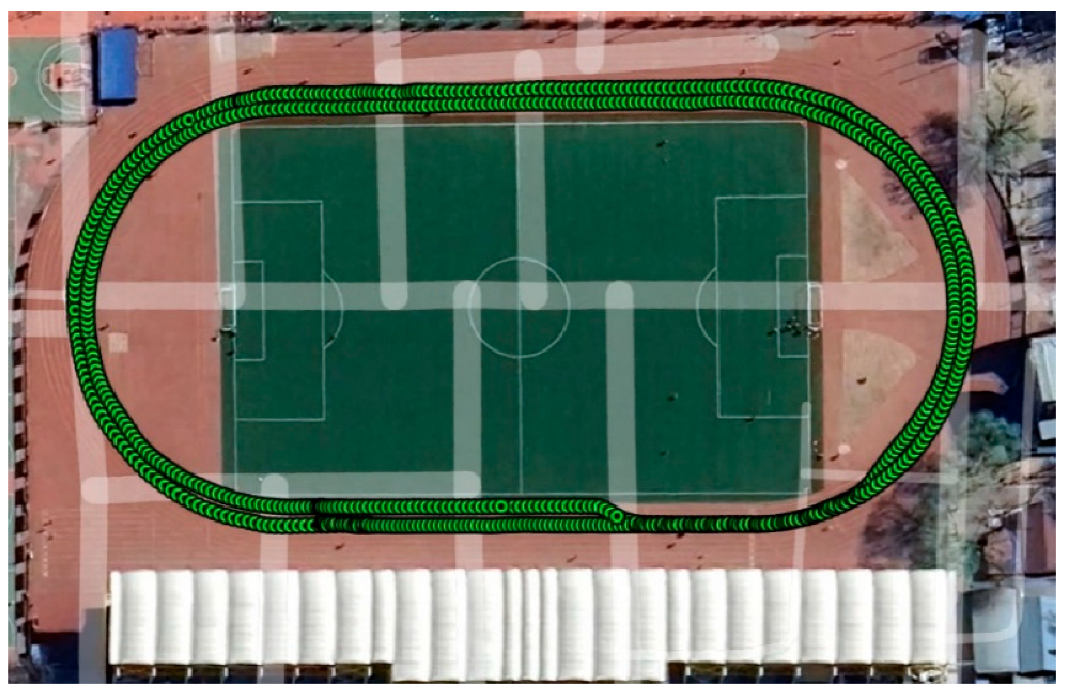
3. Data Collection and Observation Quality Assessment

To validate the performance of the presented smartphone PPP model, two field tests are arranged around the playground of China University of Geosciences (Beijing, China). The first test was the static experiment, which was arranged at 9.00 AM–12:30 PM on 4 June 2025, with a total duration of approximately 3.5 hours. The main equipment used in this experiment was a XIAO MI8 smartphone (Xiaomi, Beijing, China) (marked as MI8) and a geodesic receiver called the PANDA GNSS receiver (Pandagnss, Wuhan, China, www.pandagnss.com). The MI8 smartphone was placed under a relatively unobstructed sky environment and closely adjacent to the PANDA receiver (as shown in the subfigures of Figure 1 and Figure 2). Due to the positioning accuracy of a smartphone’s PPP being at about the sub-meter to meter level, the distance between the MI8 and the GNSS receiver’s antenna can be ignored in this work. The purpose of the static experiment is to analyze the convergence and positioning accuracy of a smartphone’s PPP, and the purpose of this dynamic test is to show the real-time positioning accuracy of the smartphone PPP model in a real application. To evaluate the positioning accuracy, the PPP solutions based on the PANDA receiver and IGS ultra-rapid precise orbit/clock products (from GFZ) are used as reference positioning results.
The second test was a dynamic experiment, arranged at 10:20 AM on 30 October 2023, and the corresponding experimental equipment and trajectory are shown in Figure 2 and Figure 3. In addition to the MI8 and the two GNSS PANDA receivers, a high-precision inertial navigation device named POS320 (NAVTIMES, Beijing, China) was also used in the dynamic experiment. The reference results of the dynamic experiment are calculated through the tightly coupled integration of RTK/INS using the GINS commercial software (GINS version 3.1.0, http://www.whmpst.com/en/imgproduct.php?aid=29, accessed on 21 April 2025).

3.1. Carrier-to-Noise Ratio

Before the positioning accuracy analysis, the C/N0, multipath errors and satellite availability of GPS and BDS satellites in both the static and kinematic tests are presented in Figure 4. The C/N0 ratio is an important indicator to show the noise level of the original GNSS observations, and it can be used to identify the quality of GNSS measurements. A larger C/N0 value means a higher-quality GNSS measurement. Figure 4 shows the variations in C/N0 ratios of these visible GPS and BDS satellites during the static experiment and dynamic experiment, and the corresponding statistical results are listed in Table 3. Accordingly, the minimum, maximum, and average values of C/N0 for these observed GPS satellites are 10.94 dB-Hz, 49.85 dB-Hz, and 37.33 dB-Hz, respectively, which are generally higher than those of BDS satellites in the static experiment. Similarly, in the dynamic experiment, the average C/N0 of the GPS satellite is also higher than the average C/N0 of these BDS satellites, with the corresponding values of 40.46 dB-Hz of GPS and 34.27 dB-Hz of BDS.

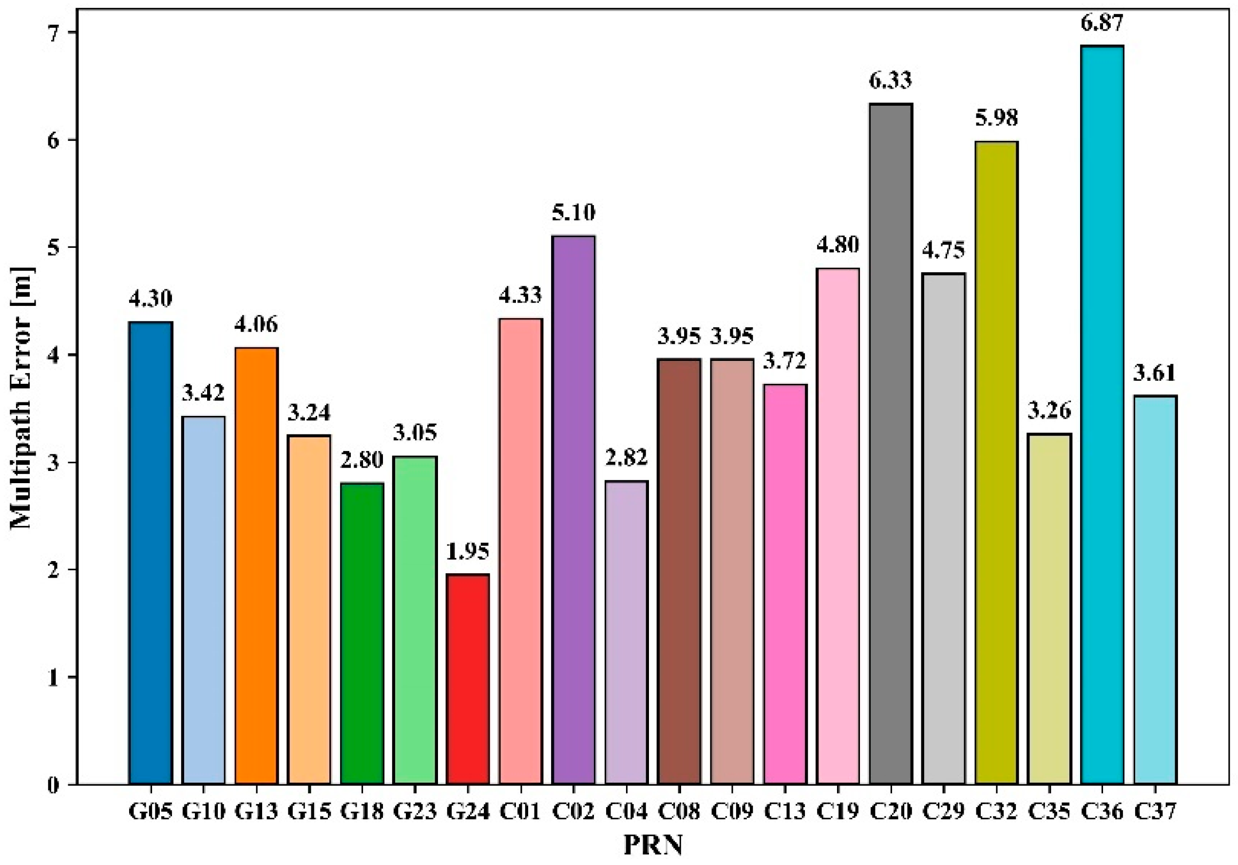
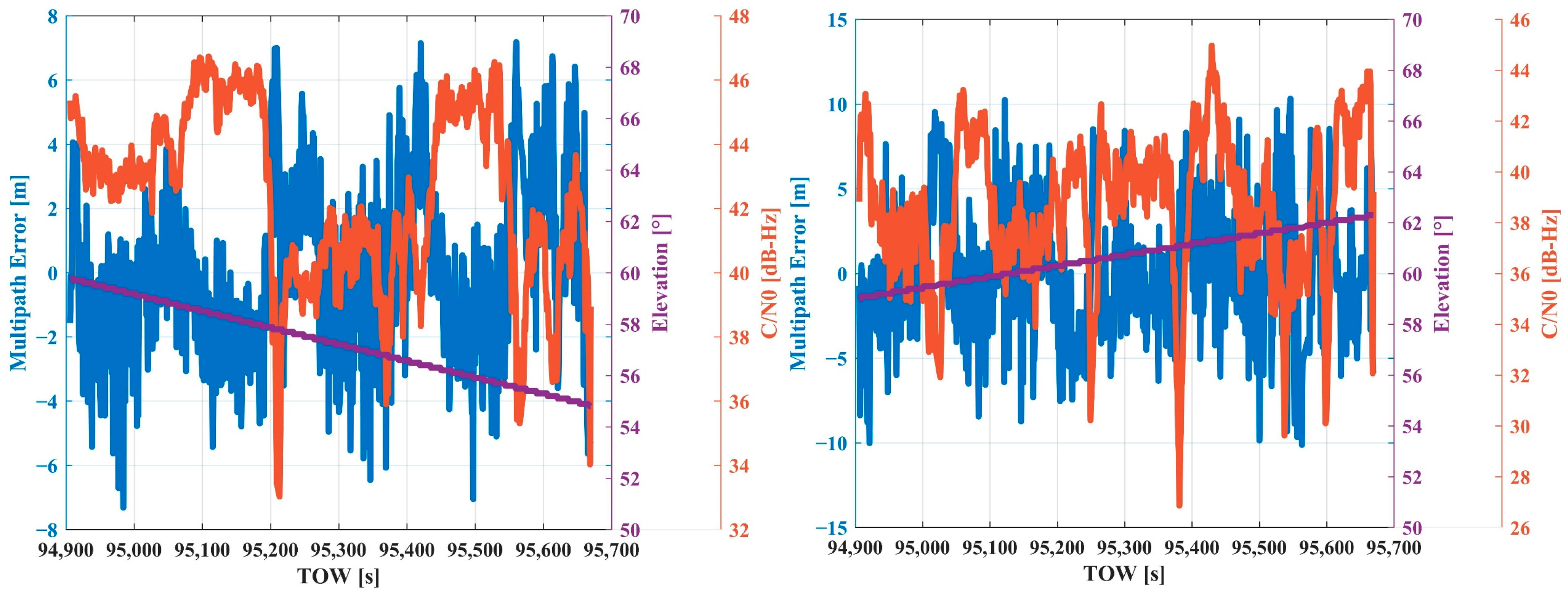
3.2. Multipath Errors

Multipath error is one of the major errors affecting the quality of GNSS observations. For the dual-frequency GNSS observations, usually, a combination of pseudo-range and carrier phase can be used to extract multipath errors. In this study, mainly single-frequency GNSS observations were available; therefore, we used the pseudo-range minus the carrier phase (CMC) to evaluate the multipath error, which can be expressed as [32,36]
C M C = P λ Φ = 2 I λ N Φ + M P + ε P + M Φ + ε Φ
where M P and M Φ denote multipath errors in pseudo-range and carrier phase, respectively. Due to the observation noise of the pseudo-range being much larger than the observation noise and multipath error of the carrier phase, Equation (34) can be approximately simplified as [36]
C M C 2 I λ N + M P + ε P
Since the ionosphere delay changes slowly over a short time, this characteristic ensures that it can be regarded as a constant. In addition, the ambiguity is a constant when there is no cycle slip. Therefore, removing the average value of the CMC in Equation (32) can eliminate the influence of the ionosphere delay and ambiguity, and the residual value (CMCR) of the CMC can be used to reflect the multipath error and measuring noise of the pseudo-range.
C M C R = C M C C M C ¯ = M P + ε P
As is known, the multipath error on a pseudo-range is larger than the measuring noise. Therefore, the CMCR can be used to characterize multipath errors. Shown in Figure 5 and Figure 6 are the statistics RMS values of multipath errors for these observed GPS and BDS satellites in both the static and dynamic experiments. Accordingly, in the static experiment, the RMS values of multipath error for these observed satellites are within 3.95 m ~ 10.71 m, except G30, which has a higher RMS value of 15.95 m. In the dynamic experiment, the RMS values of the multipath error for GPS satellites are distributed between 1.95 m and 4.30 m, while these values for BDS satellites range from 1.95 m to 4.30 m. In general, the multipath error strength of BDS satellites is larger than that of GPS satellites.
To present the relationship between the multipath error, satellite elevation angle, and C/N0, the corresponding results of G22 (GPS) and C35 (BDS) in the static experiment and that of G15 (GPS) and C19 (BDS) in the dynamic experiment are shown in Figure 7 and Figure 8, respectively, as examples. Obviously, there is an anti-correlation between the multipath errors and C/N0 values, and similar relations between multipath errors and elevation angles can also be found. However, the correlation of C/N0 and multipath error is much stronger than that of elevation angle and multipath error. Usually, lower elevations could lead to smaller C/N0 values and greater multipath errors.

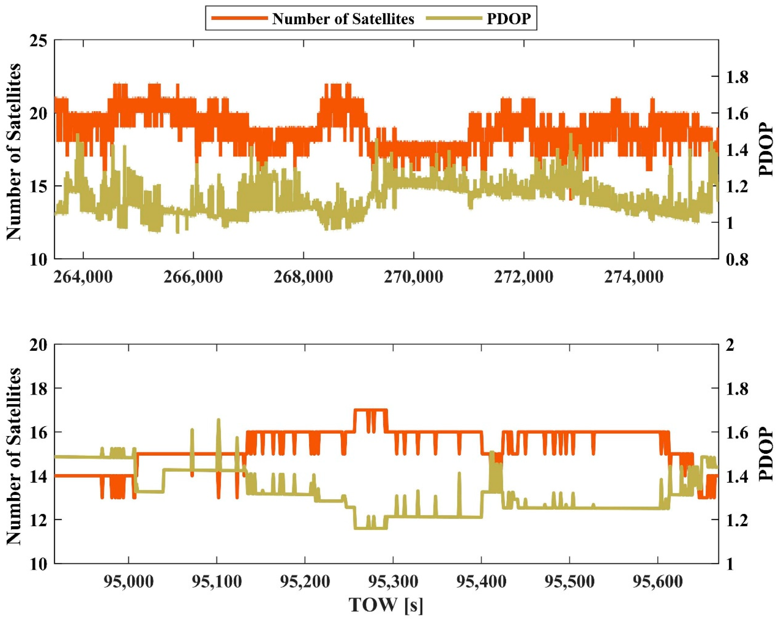
3.3. Satellite Availability and PDOP

The number of available satellites can reflect the positioning performance directly. In addition, PDOP, which represents the strength of the geometry structure between the user and observed satellites, can also be adopted to show the positioning accuracy. Theoretically, more available satellites or a smaller PDOP would mean a higher positioning accuracy. Usually, a PDOP value less than 3 is considered an ideal GNSS observing condition. Otherwise, a larger PDOP value could mean a lower positioning accuracy. Shown in Figure 9 are the number of GPS+BDS satellites and the corresponding PDOP of MI8 in the static and dynamic experiments, respectively. The number of GPS+BDS satellites observed by MI8 is about 16–22 in the static experiment, while the number of GPS+BDS satellites was approximately 13–17 in the dynamic experiment. The PDOP value of MI8 is between 1.0 and 1.4 in the static experiment, and that in the dynamic experiment is between 1.2 and 1.6. According to Figure 9, the PDOP values fluctuated frequently during the dynamic experiment, which is due to the frequent re-tracking of the GNSS satellite.

4. Results and Discussion

In this section, the impacts of precise orbit/clock products, hybrid weight function, and the mixed-frequency measurement model on a smartphone PPP are presented in detail.

4.1. Performance of the Presented Smartphone Static PPP

Based on the ultra-rapid precise orbit/clock products, these static smartphone’s GPS+BDS data were processed by (1) GPS PPP based on the hybrid weight function and the mixed-frequency measurements for L1 and L5 (GPS-MF-Com), (2) GPS+BDS PPP based on the elevation-dependent weight function and measurements for L1 and B1 (GB-SF-Ele), (3) GPS+BDS PPP based on the C/N0-dependent weight function and measurements for L1 and B1 (GB-SF-CN0), (4) GPS+BDS PPP based on the hybrid weight function and measurements for L1 and B1 (GB-SF-Com), and (5) GPS+BDS PPP based on the hybrid weight function and the mixed-frequency measurements for L1, L5, and B1 (GB-MF-Com), respectively.
The positioning errors of these five schemes are presented in Figure 10, and the corresponding RMS values are listed in Table 4. From Figure 10, it can be seen that the convergence speed of the smartphone PPP is invisible due to the low-quality GNSS observations. According to the statistical results, the positioning errors based on the elevation-dependent weight function are more difficult to converge to zero. However, the positioning errors of the smartphone PPP based on the hybrid weight function converge quickly. As is shown in Table 4, the positioning accuracy of GPS+BDS PPP based on the hybrid weight function and the mixed-frequency measurements (GB-MF-Com) is the highest among the five schemes, with the RMS values of 0.51 m, 0.67 m, and 0.71 m in the east, north, and vertical directions, respectively. In contrast, the GB-SF-Ele scheme provides the worst positioning accuracy among these five schemes, even worse than the results of the GPS-MF-Com scheme. Compared to the results of the GB-SF-Ele scheme, the positioning accuracy of the GB-SF-Com scheme was improved from 1.88 m, 2.48 m, and 3.61 m to 0.61 m, 0.69 m, and 0.83 m in the east, north, and vertical components, respectively, with position improvement percentages of 67.55%, 72.18%, and 77.01%. Such position improvement percentages are 20.69% and 15.31% in the north and vertical components, compared with the results of the GB-SF-C/N0 scheme. The GB-MF-Com scheme brings about 16.39%, 2.9%, and 14.46% improvements to the GB-SF-Com scheme and also offers 59.52%, 22.99%, and 33.64% to the GPS-MF-Com scheme in the three components. These results indicate that (1) neither the elevation-dependent weight function nor the C/N0-dependent weight function can represent the quality of smartphones’ GNSS observations accurately, and the presented hybrid weight function is one of the effective tools; (2) the mixed-frequency measurement model can increase the available measurements and further improve the smartphone positioning accuracy.

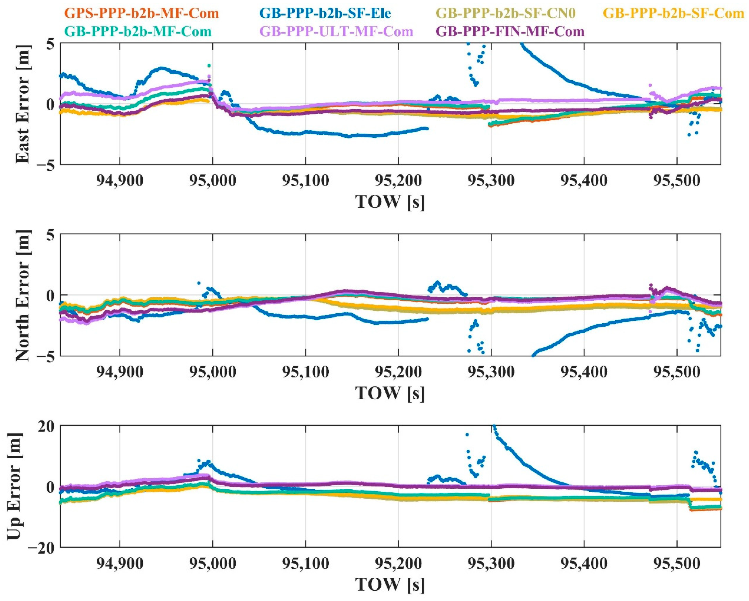
4.2. Performance of the Presented Smartphone Dynamic PPP

In this section, the results of the presented smartphone PPP based on the BDS PPP-B2b products and IGS real-time products in the dynamic test are presented. The reference results for this dynamic experiment are calculated by the tight RTK/INS integration. The dynamic smartphone’s GPS+BDS data are processed by (1) GPS-only PPP using the BDS PPP-B2b products based on the hybrid weight function and the mixed-frequency measurements for L1 and L5 (GPS-PPP-b2b-MF-Com); (2) GPS+BDS-3 PPP using the BDS PPP-B2b products based on the elevation-dependent weight function and measurements for L1 and B1 (GB-PPP-b2b-SF-Ele); (3) GPS+BDS-3 PPP using the BDS PPP-B2b products based on the C/N0-dependent weight function and measurements for L1 and B1 (GB-PPP-b2b-SF-CN0); (4) GPS+BDS-3 PPP using the BDS PPP-B2b products based on the hybrid weight function and measurements for L1 and B1 (GB-PPP-b2b-SF-Com); (5) GPS+BDS-3 PPP using the BDS PPP-B2b products based on the hybrid weight function and the mixed-frequency measurements for L1, L5, and B1 (GB-PPP-b2b-MF-Com); (6) GPS+BDS PPP using the ultra-rapid precise products provided by IGS based on the hybrid weight function and the mixed-frequency measurements for L1, L5, and B1 (GB-PPP-ULT-MF-Com); and (7) GPS+BDS PPP using the final precise products provided by IGS based on the hybrid weight function and the mixed-frequency measurements for L1, L5, and B1 (GB-PPP-FIN-MF-Com), respectively.
Figure 11 provides the positioning errors of the dynamic PPP of the MI8 smartphone by using different orbit/clock products, and the corresponding RMS values are listed in Table 5. As presented, the 3D positioning accuracy based on the BDS PPP-B2b products performs obviously worse than those based on the ultra-rapid precise products and the final products, especially while using the GPS+BDS-3 single-frequency observations based on the elevation-dependent stochastic weight model. However, such a positioning accuracy loss is mainly in the vertical direction. While evaluating the positioning accuracy in the horizontal component, these BDS PPP-B2b product-based smartphone PPP schemes can provide almost the same positioning accuracy as the IGS product-based PPP schemes, except for the GB-PPP-b2b-SF-Ele scheme. This may be because the elevation-dependent weight function cannot indicate the real quality of smartphones’ GNSS observations.
Specifically, compared to the results of the GPS-PPP-b2b-MF-Com scheme, the positioning accuracy of the GB-PPP-b2b-MF-Com scheme is improved from 0.68 m, 0.65 m, and 3.58 m to 0.61 m, 0.55 m, and 3.16 m, with the corresponding improvements of 10.29%, 15.38%, and 11.73% in the east, north, and vertical components, respectively. Compared to the results of the GB-PPP-b2b-SF-C/N0 scheme, the GB-PPP-b2b-SF-Com scheme provides 10.26%, 15.31%, and 14.99% positioning accuracy improvements in the three components, and such improvement percentages are 74.64%, 72.88%, and 36.85% when compared with the results of the GB-PPP-b2b-SF-Ele scheme. In general, the positioning accuracy of the GB-PPP-b2b-MF-Com scheme is higher than that of the GB-PPP-b2b-SF-Com scheme (0.70 m, 0.83 m, and 3.29 m), with the accuracy upgradation of 12.86%, 33.73%, and 3.95% in the east, north, and vertical directions, respectively. Moreover, compared to the positioning accuracy of the GB-PPP-FIN-MF-Com scheme (0.60 m, 0.79 m, and 0.81 m), about 8.33%, 11.39%, and 40.74% positioning accuracy degradations occur in the GB-PPP-ULT-MF-Com scheme, and about 1.67% and −30.38% positioning accuracy impacts in the GB-PPP-b2b-MF-Com. The positioning accuracy of the GB-PPP-b2b-MF-Com scheme is about three times higher than that of the GB-PPP-FIN-MF-Com scheme in the vertical component. In general, the positioning accuracy of the smartphone PPP model provided in this work can almost reach the same positioning accuracy as that presented in [28].

4.3. Experimental Result Discussion

The above results have presented the impacts of different precise orbit/clock products, the hybrid weight function, and the mixed-frequency GNSS measurements on the smartphone PPP in both the static and dynamic experiments. As is shown in Table 4 and Table 5, the positioning accuracy of the smartphone PPP based on the mixed-frequency GNSS measurements is higher than the smartphone PPP based on single-frequency GNSS observations and double-frequency GNSS observations. Also, the smartphone PPP based on the hybrid weight function is more effective in identifying GNSS data quality than the elevation-dependent weight function and the C/N0-dependent weight function. Meanwhile, based on such a smartphone PPP model, the impacts of different precise orbit/clock products on positioning have illustrated that the main influences of the BDS PPP-B2b products on smartphone PPP are in the vertical direction, with a slight impact in the horizontal component. This proves that the BDS PPP-B2b service-based smartphone PPP can be used to provide high-accuracy positioning services for these applications, focusing on the horizontal positioning accuracy.

5. Conclusions

In this paper, we provided a smartphone precise point positioning model based on the BDS PPP-B2b orbit and clock corrections, the mixed-frequency GNSS observations, and the hybrid weight function based on the C/N0 and the satellite elevation angle. The purpose of introducing the BDS PPP-B2b orbit and clock corrections instead of these IGS real-time products into the smartphone positioning system is to ensure the possibility of smartphones’ real-time high-accuracy positioning in China and its surrounding areas. This is because there is no communication limitation for the BDS PPP-B2b service, while the IGS real-time service is limited by the internet network connections. The hybrid weight’s function is to overcome the impacts of both the C/N0 and satellite elevation angle-dependent weight models on the parameter estimation accuracy. According to the static and dynamic experiments, we know that the positioning accuracy of a smartphone in real time can be upgraded visibly by using the presented PPP model compared to existing positioning methods (the built-in single point positioning and the conventional PPP).
According to the statistics in the static experiment, the positioning accuracy of the presented smartphone PPP model can provide a positioning accuracy of 0.51 m, 0.67 m, and 0.71 m in the east, north, and vertical components in terms of RMS values, which brings about 67.55%, 72.18%, and 77.01% positioning accuracy enhancements compared to the PPP based on the satellite elevation angle-dependent weight model. In the dynamic experiment, the positioning accuracies of the presented smartphone PPP based on the PPP-B2b service are 0.61 m, 0.55 m, and 3.16 m in the three directions, and are even higher in the horizontal component than in the IGS final precise product-based PPP. In general, by introducing the hybrid weight function, about 5.13%, 18.00%, and 15.15% positioning improvements and about 71.10%, 72.53%, and 53.93% can be obtained while comparing with the solutions from the C/N0-dependent PPP and the satellite-elevation-angle-dependent PPP, respectively. Furthermore, after introducing the mixed-frequency measurements into the hybrid weight function-dependent smartphone PPP, further 14.63%, 17.99%, and 9.21% positioning improvements can be obtained. Finally, by integrating the mixed-frequency PPP model and the hybrid weight function in a smartphone PPP, roughly 76.64% and 59.84% positioning enhancements in the horizontal and vertical components can be obtained compared to the results from the conventional smartphone positioning model. Considering that smartphone users focus more on the horizontal positioning than the vertical, the smartphone PPP model presented in this paper theoretically can meet the high-accuracy requirement for most IoT applications at present.
This work has proven the potential application of a smartphone PPP based on the BDS PPP-B2b service, mixed-frequency observations, and the hybrid weight function. However, it still cannot overcome the impact of GNSS satellite signal-blocking. To address this, our work in the future is to introduce inertial measurement units, geomagnetic data, barometer data, etc., into such a PPP model. In addition to the BDS PPP-B2b service used in this paper, our work will also explore the application of services like Galileo HAS in the precise positioning of smartphones.

Author Contributions

Conceptualization, Z.G. and Z.W.; data curation, Z.W. and S.L.; formal analysis, Z.W. and S.L.; funding acquisition, Z.G. and C.Y.; investigation, Z.G. and Z.W.; methodology, Z.G., Z.W., and C.Y.; project administration, Z.G. and C.Y.; software, Z.G. and Z.W.; validation, Z.W. and S.L.; visualization, Z.W. and S.L.; writing—original draft, Z.G. and Z.W.; writing—review and editing, Z.G. and C.Y. All authors have read and agreed to the published version of the manuscript.

Funding

This work was partially funded by the National Natural Science Foundation of China (NSFC) (Grants No. 42274022 and 42274024) and the National Key Research and Development Program of China (Grant No. 2022YFB3903903).

Institutional Review Board Statement

Not applicable.

Informed Consent Statement

Not applicable.

Data Availability Statement

The datasets adopted in this paper can be made available on request from the corresponding author.

Acknowledgments

Many thanks to the IGS centers for providing precise orbit/clock products. The authors also would like to thank the anonymous reviewers who gave valuable suggestions that helped to improve the quality of the manuscript.

Conflicts of Interest

The authors declare no conflicts of interest.

References

  1. Miao, W.; Li, B.; Gao, Y. The Superiority of Multi-GNSS L5/E5a/B2a Frequency Signals in Smartphones: Weight functioning, Ambiguity Resolution, and RTK Positioning. IEEE Internet Things J. 2022, 10, 7315–7326. [Google Scholar] [CrossRef]
  2. Wang, L.; Li, Z.; Wang, N.; Wang, Z. Real-time GNSS precise point positioning for low-cost smart devices. GPS Solut. 2021, 25, 1–13. [Google Scholar] [CrossRef]
  3. Håkansson, M. Characterization of GNSS observations from a Nexus 9 Android tablet. GPS Solut. 2019, 23, 21. [Google Scholar] [CrossRef]
  4. Wanninger, L.; Heßelbarth, A. GNSS code and carrier phase observations of a Huawei P30 smartphone: Quality assessment and centimeter-accurate positioning. GPS Solut. 2020, 24, 64. [Google Scholar] [CrossRef]
  5. Hou, P.; Zha, J.; Liu, T.; Zhang, B. Recent advances and perspectives in GNSS PPP-RTK. Meas. Sci. Technol. 2023, 34, 051002. [Google Scholar] [CrossRef]
  6. Xin, S.; Geng, J.; Zhang, G.; Ng, H.; Guo, J.; Hsu, L. 3D-mapping-aided PPP-RTK aiming at deep urban canyons. J. Geod. 2022, 96, 78. [Google Scholar] [CrossRef]
  7. Zumberge, J.F.; Heflin, M.B.; Jefferson, D.C.; Watkins, M.M.; Webb, F.H. Precise point positioning for the efficient and robust analysis of GPS data from large networks. J. Geophys. Res. Solid. Earth 1997, 102, 5005–5017. [Google Scholar] [CrossRef]
  8. Kouba, J.; Héroux, P. Precise point positioning using IGS orbit and clock products. GPS Solut. 2001, 5, 12–28. [Google Scholar] [CrossRef]
  9. Shinghal, G.; Bisnath, S. Conditioning and PPP processing of smartphone GNSS measurements in realistic environments. Satell. Navig. 2021, 2, 1–17. [Google Scholar] [CrossRef]
  10. Wang, J.; Wang, Y. Analysis of 5G Smart Communication Base Station Doppler-Smoothed Pseudorange Single-Point Geodesic Positioning Accuracy. J. Comput. Netw. Commun. 2023, 10, 4297044. [Google Scholar] [CrossRef]
  11. Li, G.; Geng, J. Characteristics of raw multi-GNSS measurement error from Google Android smart devices. GPS Solut. 2019, 23, 90. [Google Scholar] [CrossRef]
  12. Paziewski, J.; Fortunato, M.; Mazzoni, A.; Odolinski, R. An analysis of multi-GNSS observations tracked by recent Android smartphones and smartphone-only relative positioning results. Measurement 2021, 175, 109162. [Google Scholar] [CrossRef]
  13. Wang, J.; Zheng, F.; Hu, Y.; Zhang, D.; Shi, C. Instantaneous sub-meter level precise point positioning of low-cost smartphones. Navig. J. Inst. Navig. 2023, 70, navi.597. [Google Scholar] [CrossRef]
  14. Li, M.; Huang, T.; Li, W.; Zhao, Q.; Jiang, K. Precise point positioning with mixed single-and dual-frequency GNSS observations from Android smartphones considering code-carrier inconsistency. Adv. Space Res. 2024, 74, 2664–2679. [Google Scholar] [CrossRef]
  15. Li, G.; Geng, J. Android multi-GNSS ambiguity resolution in the case of receiver channel-dependent phase biases. J. Geod. 2022, 96, 72. [Google Scholar] [CrossRef]
  16. Wen, Q.; Geng, J.; Li, G.; Guo, J. Precise point positioning with ambiguity resolution using an external survey-grade antenna enhanced dual-frequency android GNSS data. Measurement 2020, 157, 107634. [Google Scholar] [CrossRef]
  17. Chen, B.; Gao, C.; Liu, Y.; Sun, P. Real-time precise point positioning with a Xiaomi MI 8 android smartphone. Sensors 2019, 19, 2835. [Google Scholar] [CrossRef]
  18. Zangenehnejad, F.; Jiang, Y.; Gao, Y. GNSS Observation Generation from Smartphone Android Location API: Performance of Existing Apps, Issues and Improvement. Sensors 2023, 23, 777. [Google Scholar] [CrossRef]
  19. Liu, Q.; Ying, R.; Wang, Y.; Liu, P. Pseudorange double difference algorithm based on duty-cycled carrier phase smoothing on low-power smart devices. In China Satellite Navigation Conference (CSNC) 2018 Proceedings; Springer: Singapore, 2018; Volume I, pp. 415–430. [Google Scholar]
  20. Han, Z.; Wang, X.; Zhang, J.; Xin, S.; Huang, Q.; Shen, S. An Improved Velocity-Aided Method for Smartphone Single-Frequency Code Positioning in Real-World Driving Scenarios. Remote Sens. 2024, 16, 3988. [Google Scholar] [CrossRef]
  21. Gill, M.; Bisnath, S.; Aggrey, J.; Seepersad, G. Precise point positioning (PPP) using low-cost and ultra-low-cost GNSS receivers. In Proceedings of the 30th International Technical Meeting of The Satellite Division of The Institute of Navigation (ION GNSS+ 2017), Portland, OR, USA, 25–29 September 2017; pp. 226–236. [Google Scholar]
  22. Zhang, X.; Tao, X.; Zhu, F.; Shi, X.; Wang, F. Quality assessment of GNSS observations from an Android N smartphone and positioning performance analysis using time-differenced filtering approach. GPS Solut. 2018, 22, 1–11. [Google Scholar] [CrossRef]
  23. Liu, H.; Gao, Z.; Wang, L.; Xu, Q.; Yang, C. Reliable Positioning Model of Smartphone Sensors and User Motions Tightly Enhanced PDR. IEEE Internet Things J. 2024, 11, 30925–30938. [Google Scholar] [CrossRef]
  24. Yang, Y.; Ding, Q.; Gao, W.; Li, J.; Xu, Y.; Sun, B. Principle and performance of BDSBAS and PPP-B2b of BDS-3. Satell. Navig. 2022, 3, 5. [Google Scholar] [CrossRef]
  25. Liu, C.; Gao, W.; Liu, T.; Wang, D.; Yao, Z.; Gao, Y.; Nie, X.; Wang, W.; Li, D.; Zhang, W.; et al. Design and implementation of a BDS precise point positioning service. Navigation 2020, 67, 875–891. [Google Scholar] [CrossRef]
  26. Nie, Z.; Xu, X.; Wang, Z.; Du, J. Initial assessment of BDS PPP-B2b service: Precision of orbit and clock corrections, and PPP performance. Remote Sens. 2021, 13, 2050. [Google Scholar] [CrossRef]
  27. Wu, M.; Wang, L.; Xie, W.; Yue, F.; Cui, B. Performance Evaluation and Application Field Analysis of Precise Point Positioning Based on Different Real-Time Augmentation Information. Remote Sens. 2024, 16, 1349. [Google Scholar] [CrossRef]
  28. Zhao, L.; Zhai, W. Assessment of PPP Using BDS PPP-B2b Products with Short-Time-Span Observations and Backward Smoothing Method. Remote Sens. 2025, 17, 25. [Google Scholar] [CrossRef]
  29. European Global Navigation Satellite Systems Agency. Using GNSS Raw Measurements on Android Devices; Publications Office of the European Union: Prague, Czech Republic, 2018. [Google Scholar]
  30. China Satellite Navigation Office. BeiDou Navigation Satellite System Signal in Space Interface Control Document Precise Point Positioning Service Signal PPP-B2b (Version 1.0); China Satellite Navigation Office: Beijing, China, 2020. [Google Scholar]
  31. Wu, P.; Lou, Y.; Zhang, W.; Liu, W.; Li, Y.; Zhao, Q. Evaluation of real-time kinematic positioning performance of the BDS-3 PPP service on B2b signal. GPS Solut. 2023, 27, 192. [Google Scholar] [CrossRef]
  32. Li, X.; Wang, H.; Li, X.; Li, L.; Lv, H.; Shen, Z.; Xia, C.; Gou, H. PPP rapid ambiguity resolution using Android GNSS raw measurements with a low-cost helical antenna. J. Geod. 2022, 96, 65. [Google Scholar] [CrossRef]
  33. Cheng, S.; Wang, F.; Li, G.; Geng, J. Single-frequency multi-GNSS PPP-RTK for smartphone rapid centimeter-level positioning. IEEE Sens. J. 2023, 23, 21553–21561. [Google Scholar] [CrossRef]
  34. Dach, R.; Hugentobler, U.; Fride, P. Bernese GPS Software Version 5.0.; University of Bern: Bern, Switzerland, 2007. [Google Scholar]
  35. Li, Y.; Cai, C.; Xu, Z. A Combined Elevation Angle and C/N0 Weighting Method for GNSS PPP on Xiaomi MI8 Smartphones. Sensors 2022, 22, 2804. [Google Scholar] [CrossRef]
  36. Li, W.; Zhu, X.; Chen, Z.; Dai, Z.; Li, J.; Ran, C. Code multipath error extraction based on the wavelet and empirical mode decomposition for Android smart devices. GPS Solut. 2021, 25, 91. [Google Scholar] [CrossRef]
Figure 1. Equipment (MI8, PANDA GNSS receiver, GNSS antenna, and MI8) (a) and the sky-plots of GPS and BDS (b) in the static experiment.
Applsci 15 07169 g001
Figure 2. Equipment (MI8, PANDA GNSS receiver, POS320, GNSS antenna, and MI8) (a) and the sky-plots of GPS and BDS (b) in the dynamic experiment.
Applsci 15 07169 g002
Figure 3. Reference trajectory for the dynamic experiment.
Applsci 15 07169 g003
Figure 4. Variation in MI8’s C/N0 for visible GPS/BDS satellites in the static experiment (left) and dynamic experiment (right).
Applsci 15 07169 g004
Figure 5. RMS of multipath error for GPS and BDS satellites in the static experiment.
Applsci 15 07169 g005
Figure 6. RMS of multipath error for GPS and BDS satellites in the dynamic experiment.
Applsci 15 07169 g006
Figure 7. Correlation of C/N0, satellite elevation angle, and multipath error for G22 and C35 in the static experiment.
Applsci 15 07169 g007
Figure 8. Correlation of C/N0, satellite elevation angle, and multipath error for G15 and C19 in the dynamic experiment.
Applsci 15 07169 g008
Figure 9. Number of visible GPS+BDS satellites and the corresponding PDOP for MI8 in the static experiment (above) and the dynamic experiment (below).
Applsci 15 07169 g009
Figure 10. Positioning errors of different PPP modes based on different weight functions in the static test.
Applsci 15 07169 g010
Figure 11. Positioning errors of dynamic PPP using different products based on different weight functions.
Applsci 15 07169 g011
Table 1. Important variables and their meanings in the GNSS clock interface.
FiledsDescription
TimesNanosAndroid terminal GNSS receiver time
BiasNanosThe sub-nanosecond-level deviation between the Android GNSS receiver clock and real GPS time
FullBiasNanosNanosecond-level deviation between the Android GNSS receiver clock and real GPS time
DriftNanosPerSecondAndroid GNSS receiver clock drift
LeapSecondLeap second associated with the clock’s time
Table 2. Important variables and meanings.
FiledsDescription
SvidSatellite ID
ConstellationTypeConstellation type
StateCurrent state of the GNSS engine
ReceivedSvTimeNanosReceived GNSS satellite time at the measurement time
Cn0DbHzCarrier-to-noise density
CarrierFrequencyHzCarrier frequency at which codes and messages are modulated
TimeOffsetNanosTime offset at which the measurement was taken in nanoseconds
CarrierCyclesNumber of full carrier cycles between the satellite and the receiver
PseudorangeRatemetersperSecondPseudo-range rate at the timestamp
AccumulatedDeltaRangeMetersAccumulated distance values since the last channel initialization
AccumulatedDeltaRangeStateState parameters of carrier phase observation values
Table 3. C/N0 values of these visible GPS L1 and BDS B1 satellites in the MI8 smartphone.
Static (dB-Hz)Dynamic (dB-Hz)
MINMAXAVGMINMAXAVG
GPS9.55 47.76 36.50 24.9747.3840.46
BDS9.02 46.91 32.74 9.2049.1234.27
Table 4. Position RMS of static PPP for MI8 based on different positioning modes.
Positioning ModesEast (m)North (m)Up (m)
GPS-MF-Com1.260.871.07
GB-SF-Ele1.882.483.61
GB-SF-CN00.610.870.98
GB-SF-Com0.610.690.83
GB-MF-Com0.510.670.71
Table 5. Positioning RMS of dynamic PPP accuracy for MI8 based on different weight functions.
Positioning ModesEast (m)North (m)Up (m)
GPS-PPP-b2b-MF-Com0.68 0.65 3.58
GB-PPP-b2b-SF-Ele2.76 3.06 5.21
GB-PPP-b2b-SF-CN00.78 0.98 3.87
GB-PPP-b2b-SF-Com0.70 0.83 3.29
GB-PPP-b2b-MF-Com0.61 0.55 3.16
GB-PPP-ULT-MF-Com0.65 0.88 1.14
GB-PPP-FIN-MF-Com0.60 0.79 0.81
Disclaimer/Publisher’s Note: The statements, opinions and data contained in all publications are solely those of the individual author(s) and contributor(s) and not of MDPI and/or the editor(s). MDPI and/or the editor(s) disclaim responsibility for any injury to people or property resulting from any ideas, methods, instructions or products referred to in the content.

