Article

Increasing Deformation Energy Absorption of AM Drone Fuselages Using a Low-Density Polymeric Material

1
Department of Aeronautical Engineering, Vilnius Gediminas Technical University (VILNIUS TECH), Linkmenų str. 28-4, 08217 Vilnius, Lithuania
2
Laboratory of Innovative Building Structures, Vilnius Gediminas Technical University (VILNIUS TECH), Saulėtiekio Av. 11, 10223 Vilnius, Lithuania
3
Department of Reinforced Concrete Structures and Geotechnics, Vilnius Gediminas Technical University (VILNIUS TECH), Saulėtiekio Av. 11, 10223 Vilnius, Lithuania
*
Author to whom correspondence should be addressed.
Appl. Sci. 2025, 15(13), 7164; https://doi.org/10.3390/app15137164
Submission received: 10 June 2025 / Revised: 22 June 2025 / Accepted: 24 June 2025 / Published: 25 June 2025

Abstract

Featured Application

The presented design for an additive manufacturing (DfAM) concept features an internal metastructure that combines different density parts to enhance the energy absorption capacity and mechanical resistance of a drone fuselage segment, meeting the targeted weight requirement.

Abstract

This study investigates the potential of low-density polymeric materials to enhance the deformation energy absorption of drone fuselage components manufactured using fused filament fabrication (FFF). Two materials—PLA (polylactic acid) and LW-PLA (lightweight polylactic acid)—were selected based on their accessibility, printability, and prior mechanical characterizations. While PLA is widely used in additive manufacturing, its brittleness limits its suitability for components subjected to accidental or impact loads. In contrast, LW-PLA exhibits greater ductility and energy absorption, making it a promising alternative where weight reduction is critical and structural redundancy is available. To evaluate the structural efficiency, a simplified analysis scenario was developed using a theoretical 300 J collision energy, not as a design condition, but as a comparative benchmark for assessing the performance of various metastructural configurations. The experimental results demonstrate that a stiffening core of the LW-PLA metastructure can reduce the component weight by over 60% while maintaining or improving the deformation energy absorption. Modified prototypes with hybrid internal structures demonstrated stable performances under repeated loading; however, the tests also revealed a buckling-like failure of the internal core in specific configurations, highlighting the need for core stabilization within metastructures to ensure reliable energy dissipation.

1. Introduction

The increasing interest in additive manufacturing (AM) technologies today is driven by various factors, including their speed and accessibility for average or novice consumers compared to traditional acquisition methods for drones [1,2]. The inherent flexibility of AM technologies in geometry creation and the ability to produce lightweight structures have opened up new frontiers in customized, rapid, and cost-effective prototyping [3,4]. A key enabler of this innovation is design for additive manufacturing (DfAM) [5], which integrates computational design with manufacturing constraints to optimize both shape and performance. Nevertheless, the physical properties of the manufactured components hinge on the production conditions, including the polymer material, printing temperature, and speed [6,7,8].
Several studies have focused on utilizing DfAM principles to reduce weight and enhance aerodynamic efficiency by employing varying levels of complexity in internal geometries and applying topological optimization techniques to drone frames and housings, e.g., [2,6,9,10,11,12,13,14,15,16,17,18,19,20,21,22]. Table 1 summarizes the current research trends and identifies gaps in the literature. A growing area of research in this field centers on the mechanical performance of AM drone components, specifically their ability to withstand mechanical loads and absorb energy during impacts [2,16]. This capability is crucial for ensuring flight safety and enhancing crashworthiness. Research into various polymer materials, particularly polylactic acid (PLA), has shown encouraging results due to their advantageous mechanical properties and suitability for fused filament fabrication (FFF). However, the natural brittleness of traditional PLA has led to investigations into modified or lightweight PLA composites (LW-PLA), which provide improved ductility and higher strain energy absorption [12,13,14,15]. Studies by Park and Lee [13], Vălean et al. [14], and Jimenez-Martinez et al. [15] have demonstrated that modifications to internal structures, including lattice infills and shell thickness, can significantly influence energy absorption properties. Despite these advancements, a gap remains in experimentally validating how internal geometric modifications within FFF parts affect deformation energy absorption under quasi-static and dynamic loads, particularly in drone-specific applications [2]. While simulation studies and theoretical models exist in the literature, empirical studies focusing on DfAM strategies tailored to real-world use cases, such as drone impact resistance, are limited [17,18]. Moreover, most of the literature isolates material behavior from structural optimization (e.g., [9,10,12]), whereas a holistic view—integrating material selection, internal geometry, and weight constraints—is crucial for effectively designing drone components [19,20].
Recent research has also focused on lightweight structures that utilize porous materials or foamed filaments [6,11,12,13,21]. These materials can reduce weight while maintaining structural integrity, particularly under repeated loading scenarios. Research conducted by Park and Lee [13] highlights the potential of low-density polymers for energy-dissipative applications. Rizzo et al. [21] identified the outstanding performance of LW-PLA under dynamic loads. However, challenges remain regarding the mechanical strength and dimensional stability of the porous materials [7]. Still, this strategy aligns with the growing goals of sustainability and cost-effectiveness, particularly within the consumer drone industry, where economical and easily repairable components are crucial [2]. A combination of materials further enhances the mechanical performance of AM objects [6,13,22], but it also raises concerns about material compatibility and durability [7,23]. Therefore, this study employs the internal structure hybridization approach, which combines different stiffness and density parts of the same material to achieve a desired mechanical performance, forming metastructures, as discussed in [24].
Zhang et al. [25] demonstrated that such internal architectures can significantly improve energy absorption, stiffness-to-weight ratios, and failure resistance in polymer-based components. For instance, topology optimization and lattice-based infill strategies have been employed to create functionally graded structures that outperform uniform infill designs in both static and dynamic scenarios [26,27,28]. Despite these promising developments, the practical implementation of metastructures in drone applications remains limited, particularly when considering the constraints of consumer-grade 3D printers and accessible materials.
To evaluate the effectiveness of these advanced designs, mechanical testing protocols must go beyond traditional strength metrics and incorporate energy-based assessments. Deformation energy—quantified as the area under the load–displacement curve—has emerged as a reliable indicator of a structure’s ability to absorb impact or collision energy [28,29,30]. However, standardized methods for such evaluations are still lacking, especially for lightweight AM components. Due to the limited tension resistance of polymeric components, compression tests are typically used to estimate the mechanical performance of AM parts [25,27,29,30]. This gap is particularly relevant in the context of drone fuselage design, where both weight and crashworthiness are critical [2]. The present study addresses this need by experimentally validating the compression deformation energy absorption of FFF components made from PLA and LW-PLA. The latter material, known for its foamed microstructure and reduced density, presents a compelling alternative to conventional PLA, particularly in applications where weight savings are crucial without compromising mechanical resilience [21].
This investigation builds upon the research program [12] focused on additive drone manufacturing, utilizing a simple desktop printer and commercially available polymeric materials. The selection of PLA and LW-PLA in this study is also based on the findings of the investigation [12], which systematically evaluated the mechanical and fabrication characteristics of various polymeric filaments for drone applications. PLA was identified as a favorable material due to its non-toxicity, ease of processing, and cost-effectiveness, while LW-PLA has demonstrated promising potential for weight-sensitive applications. Šostakaitė et al. [12] provided a comparative overview of key material properties, including tensile strength, modulus of elasticity, and thermal behavior. These findings, combined with the materials’ compatibility with desktop FFF printers, support the selection of PLA for the current study, which focuses on enhancing deformation energy absorption in drone fuselage components. Recent studies have further confirmed the suitability of PLA-based materials for drones, highlighting their favorable strength-to-weight ratio, printability, and adaptability to complex geometries [31,32,33]. Additionally, LW-PLA has been increasingly recognized for its potential in lightweight drone applications, particularly where energy absorption and structural efficiency are crucial [2,32,33].
This experimental study assesses the feasibility of utilizing low-density polymers for drone fuselage components. Through controlled fabrication utilizing FFF technology and mechanical testing under monotonic and repeated compression, this research assesses the impact of internal structural modifications on the deformation energy absorption and mechanical resistance. It employs two types of polymeric materials, PLA and LW-PLA. A simplified example showcases the DfAM potential, while theoretical calculations evaluate the energy released during a drone collision. Although this energy is not a design condition, it serves as a comparative benchmark for assessing the performance of various metastructural configurations, combining different density parts to meet the targeted weight while enhancing the energy absorption and mechanical resistance of the FFF fuselage segment.

2. Materials and Methods

All samples were produced using a P1S 3D printer (BAMBU LAB, Shenzhen, China). It features an enclosed build chamber to maintain stable thermal conditions during the sample fabrication process. The internal pattern shape of AM components affects their mechanical resistance [25,26,27,28] and may determine the optimization object. However, preliminary tests [34,35] revealed the mechanical efficiency of rectangular lattice patterns, which were used as the default option in BAMBU STUDIO software (BAMBU LAB, Version 1.10.1.50, Shenzhen, China) to create the fabrication models for the compressive tests considered in this study. Therefore, this illustrative test program assumed this pattern while varying only the density. All mechanical tests were conducted at the Laboratory of Innovative Building Structures at VILNIUS TECH.

2.1. Material Tests

The mechanical performance of polymeric materials depends on the manufacturing conditions and may differ from the manufacturer’s specified properties [34,36]. Therefore, the preliminary tests characterized the mechanical performance of the polymeric materials employed in this experimental campaign, which involved PLA and LW-PLA materials from COLORFABB (Belfeld, The Netherlands). For comparison purposes, Table 2 presents the physical properties of the polymeric materials as specified by the manufacturer [37,38]. In this table, E is the modulus of elasticity; ft and εu are the tensile strength and ultimate strain; Tg and Tm are the glass transition and melting temperatures; the x and y axes determine the filament deposition plane; and z is the vertical axis.
The mechanical tests of both materials in this study employed cylinders with dimensions of ∅22.6 × 40 mm2, fabricated with 98% infill. BAMBU STUDIO software (BAMBU LAB, Version 1.10.1.50, Shenzhen, China) was used to create the fabrication models. All the cylinders were printed using the P1S 3D printer (BAMBU LAB, Shenzhen, China), equipped with a 0.4 mm nozzle and a textured build plate. All samples were built with a layer height of 0.24 mm. The extrusion temperature of the PLA was set to 220 °C, with a flow rate (FR) of 98% and a volumetric print speed (VS) of 20 mm3/s. According to the technical datasheet for PLA and LW-PLA from COLORFABB (Belfeld, The Netherlands), the optimal print bed temperature ranges from 50 °C to 60 °C [37,38]. Therefore, this study used a print bed temperature of 55 °C to ensure proper bed adhesion while minimizing the risk of the sample debonding.
The extruder temperature activates the LW-PLA foaming additive and controls the density of the fabricated material [13,38]. Therefore, the selection of the maximum VS and FR parameters was based on a preliminary calibration program designed to maximize the weight reduction of LW-PLA while maintaining the dimensional stability. The initial calibration program involved four cylindrical specimens with a diameter of 22.6 mm and a height of 40 mm, printed with varying maximum VS values ranging from 5 mm3/s to 12 mm3/s and FR values from 53% to 98%. The fabrication results showed that the specimen printed at 5 mm3/s with a 53% FR had the lowest mass (6.7 g), compared to the heaviest specimen (11.5 g) produced at 12 mm3/s with a 98% FR, nearly doubling the weight reduction. An intermediate condition (12 mm3/s and 53% FR) yielded an 11.0 g specimen, indicating a limited influence of FR on the weight. Employing VS above 8 mm3/s caused significant increases in mass and decreases in foaming effects. These findings are consistent with results reported by Park and Lee [13]. Based on these insights, the 5 mm3/s VS and 53% FR were chosen for the FFF of the LW-PLA components to maximize the weight reduction effect. The extruder temperature was increased to 230 °C. Furthermore, print cooling was disabled to ensure consistent extrusion and material expansion during the deposition process.
Six specimens of each material were produced, with an average weight of 19.6 ± 0.1 g for the PLA cylinders and 7.0 ± 0.3 g for the LW-PLA cylinders. These results indicate a 62.6% weight reduction for the reference PLA specimens, underscoring the adequacy of the fabrication settings used in this study.
The mechanical tests utilize a 75 kN capacity servomechanical testing apparatus, H75KS (TINIUS OLSEN, Redhill, UK), which boasts a position measurement accuracy of ±0.01%. A 50 kN load cell with a precision of 0.5% was used in the compression tests. Two linear variable displacement transducers (LVDTs, AHLBORN, Holzkirchen, Germany) monitored the vertical displacements, achieving an accuracy of 0.02%. The following analysis uses the average displacement values. The loading velocity was kept at 0.25 mm/min. Data from the load cell and vertical displacement sensors were recorded using an ALMEMO 2890-9 data acquisition system (AHLBORN, Holzkirchen, Germany), which captured five readings per second. Figure 1 displays the sliced model, test setup, and samples, and Figure 2 shows the test results. Figure 1a,b show the numerical model (including the internal pattern) prepared for the FFF, and Figure 1c depicts the test setup, including the digital camera used to capture the deformation shape of the test specimens. A single-lens reflex camera, the EOS 77D SLR (CANON Inc., Tokyo, Japan), with an 18–135 mm EF-S lens (CANON Inc., Tokyo, Japan) and a remote control (ensuring image stability), was positioned 0.4 m from the sample. The camera was set to the following settings: 1/200 s exposure, f/4.5 aperture, 24 mm focal length, and ISO 100 light sensitivity.
Figure 2 presents the test results for three PLA samples and four LW-PLA cylinders, as the remaining specimens underwent repeated loading and are not included in this study. Two of the cylinders (shown in Figure 1d) were tested up to a 7 mm deformation to accelerate the testing process. The deformations of the other samples, illustrated in Figure 2, exceed 20 mm, resulting in significant losses in the initial geometry and hardening response due to the increase in the cross-section of the deformed specimens.

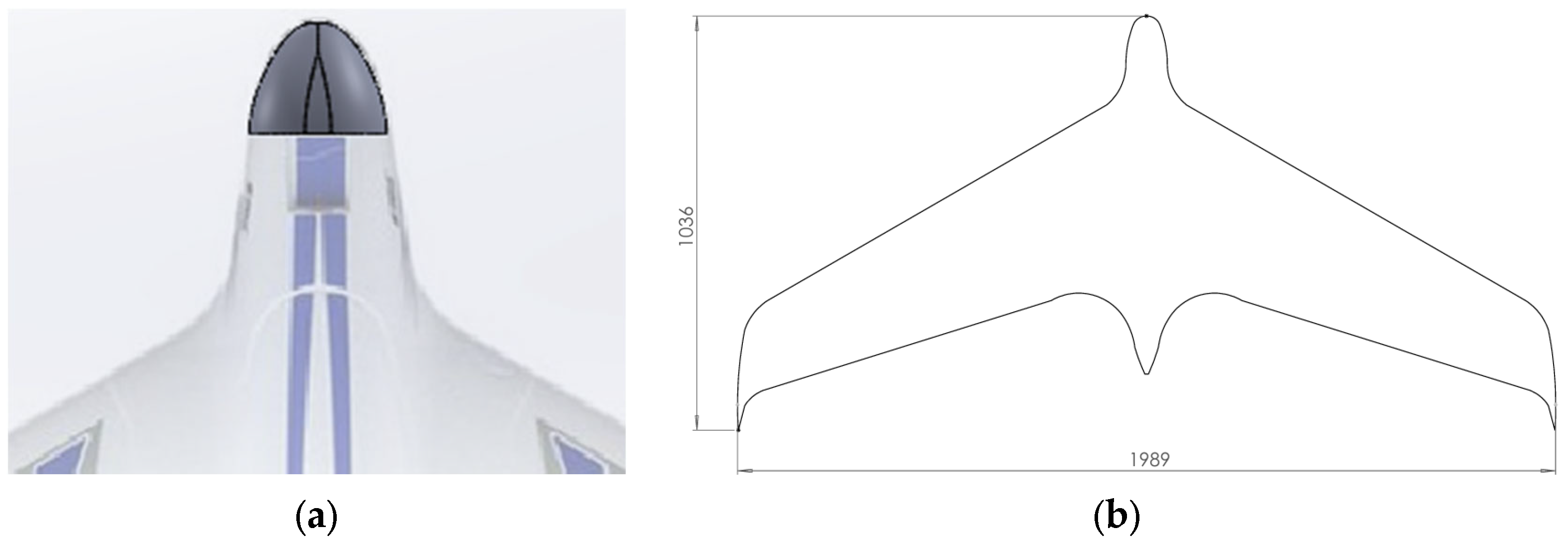
2.2. Drone Prototype and Collision Analysis

This study examines the application of 3D printing technologies in manufacturing unmanned aerial vehicles (UAVs), with a specific focus on material selection and its impact on structural performance, particularly in terms of deformation energy absorption, evaluating the possibility of replacing expanded polyolefin (EPO). This foam-like polymer is typically used in UAV construction due to its low cost, ease of shaping, and lightweight properties. While EPO offers apparent advantages, it presents limitations in UAV design, particularly in terms of internal space utilization. Due to its foam structure, EPO occupies a significant portion of the fuselage, thereby reducing the available volume for critical payloads, such as sensors, cameras, batteries, or other mission-specific equipment. This limitation is especially relevant in UAV applications, where efficient transportation of cargo or equipment is crucial. To address this issue, this research proposes substituting EPO with additively manufactured polymeric materials, such as PLA or LW-PLA, which could provide comparable or enhanced mechanical performance while increasing the internal volume available for useful loads.
Three models [39,40,41] were chosen due to their similar physical characteristics, particularly their wingspan and wing surface area, as well as their broad adoption within the UAV enthusiast community. All three are manufactured initially from EPO and share similar constraints related to payload space. After comparing the design features and practical constraints of the selected UAVs, the OPTERRA 2M WING [41] stood out as the most suitable candidate for further investigation and material substitution due to the possibility of isolating the front part of the fuselage, which is already formed as a separate, prototyping-ready fragment (Figure 3a). Its flying wing configuration simplified the structural geometry, making it more compatible with 3D printing processes. Additionally, replacing its foam nose part with 3D-printed materials could significantly enhance the usable internal volume without compromising the flight performance. The potential to redesign and optimize the internal structure through additive manufacturing opens new avenues for increasing the payload capacity and improving the mechanical robustness of UAVs.
The OPTERRA 2M WING (Figure 3b) is a flying-wing UAV renowned for its streamlined aerodynamic profile and large wingspan, which contribute to its inherent stability and flight efficiency. The manufacturer specifies the following drone characteristics [41]: wingspan = 1989 mm; fuselage length = 1036 mm; wing area = 6.66 × 105 mm2; flying weight = 1899 g; cruise speed = 64 km/h; and flying time = 30 min. Its center of gravity aligns with the dimples located just in front of the finger pockets on the bottom of the fuselage. This study presents a simplified analysis example, focusing on the front part of the drone fuselage (Figure 3a), while overlooking the support and installation details of the prototype.
To evaluate the structural efficiency, the analysis scenario employs a theoretical drone collision energy, not as a design condition but as a comparative benchmark for assessing the performance of metastructural configurations. The analysis addresses the deformation energy released during the frontal collision of the drone. The calculations assume a rigid impact along with the manufacturer’s specified flying weight, m, and cruise speed, v, as described above. The following equation determines the kinetic collision energy:
U = η m · v 2 2 ; 0 < η 1 ,
where η is a material energy absorption factor; for simplicity, this study assumes η = 1. Thus, 299.7 J serves as the reference for the comparative analysis.

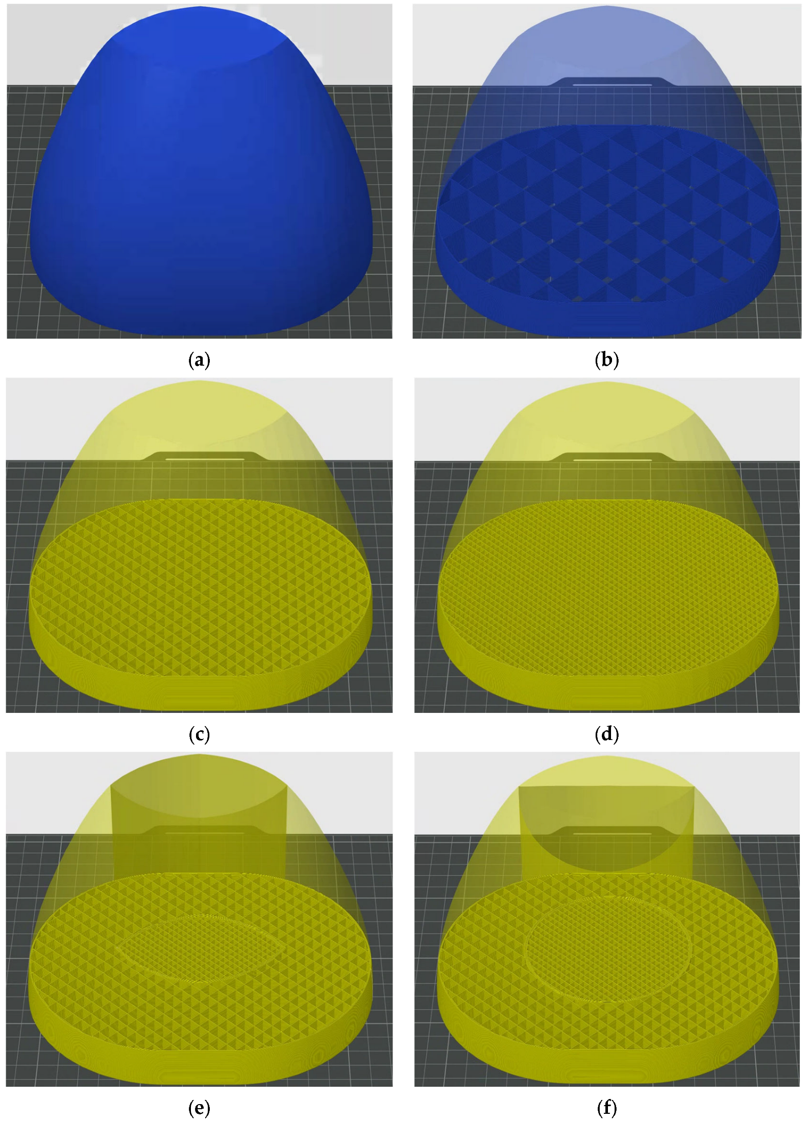
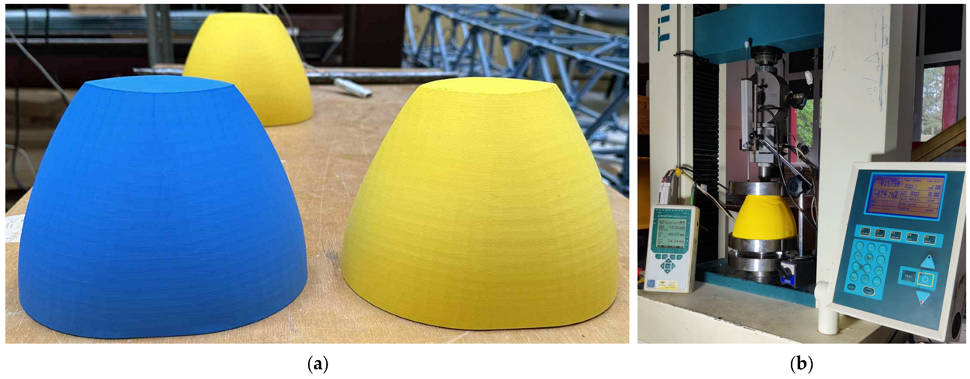
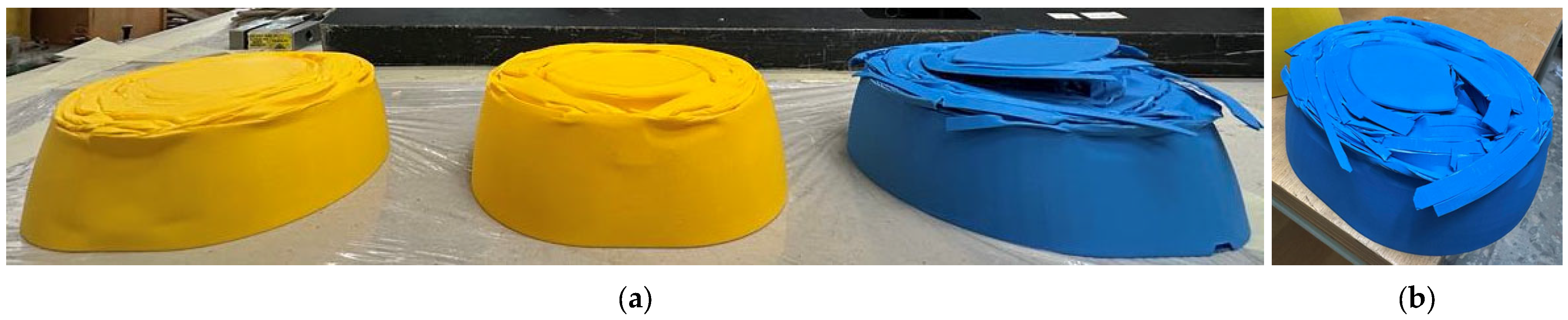
2.3. Prototyping and Compression Tests

This study utilizes SOLIDWORKS software (Educational Edition 2023 SP2.1, DASSAULT SYSTÈMES, Vélizy-Villacoublay, France) to create the fuselage front fragment (Figure 3b) for prototyping purposes. The compressive tests characterize the mechanical resistance of the FFF specimens. To ensure a flat contact surface with the testing apparatus, the height of the prototype was reduced by 15%, disregarding the top part of the fragment shown in Figure 3b. This reduction has decreased the nominal weight of the part specified by the manufacturer [41] to 155.7 g. This value determined the reference for the FFF prototype design. The prototyping and mechanical tests were conducted in two stages due to LW-PLA’s sensitivity to manufacturing settings, specifically to achieve a particular weight for the detailed prototype. As previously (Section 2.1), the prototyping was conducted using a P1S 3D printer (BAMBU LAB, Shenzhen, China), and the mechanical tests employed a servomechanical testing apparatus, H75KS (TINIUS OLSEN, Redhill, UK). A 50 kN capacity load-cell measured the compression reaction, and two LVDT devices measured the vertical displacements. Thus, the following analysis employs the average displacement values to diminish the eccentricity effect on the deformation assessment results.

2.3.1. Preliminary Prototyping and Compression Tests

Figure 4 shows the CAD models prepared for the sample manufacturing using BAMBU STUDIO software (BAMBU LAB, Version 1.10.1.50, Shenzhen, China). The first prototyping trial included the reference PLA specimen (Figure 4a,b), which was designed with a target weight of 155.7 g and resulted in a final printed weight of 156.5 g, with a 4% grid infill density. Two alternative samples (Figure 4c,d) were produced from LW-PLA using the fabrication settings described in Section 2.1, which were selected to activate the material’s foaming behavior. To achieve the designed target weight of 155.7 g, Sample 1 was fabricated with a 13% grid infill density, while Sample 2 was produced with an increased 24% grid infill density. This variation was necessary because of the material’s sensitivity to the printing conditions mentioned above. Table 3 shows the fabrication settings for all fuselage prototypes.
Figure 5 shows the first three specimens from Table 3 prepared for the test and the test setup. Figure 6 illustrates the failure shapes of the tested prototypes, with a particular focus on the fracture defragmentation of the Reference fuselage part. Figure 7a shows the load–vertical displacement diagrams of the test samples shown in Figure 6a. Differences in the mechanical performances are apparent, but there is no definite criterion to compare the structural resistances of these prototypes. Therefore, this study employed the deformation energy approach [35] for comparison purposes, using the impact energy value determined in Section 2.2. This energy determines the area under the load–displacement diagram. Thus, Figure 7b highlights the deformation energy amount corresponding to a 300 J impact effect; the vertical dashed lines indicate the deformation value necessary to release the target impact energy.
Thus, Figure 7b illustrates the enhancement in the energy absorption capacity of the LW-PLA samples compared to the Reference PLA specimen. In this figure, shaded areas under the load–displacement curves represent the deformation energy equivalent to a 300 J collision energy, with vertical dashed lines marking the corresponding displacement thresholds. However, this improvement may result from the weight increase in the front part of the fuselage prototypes (Table 3). Therefore, a further optimization procedure focused on the internal prototype structure, using the mechanical resistance of Sample 2 as the reference and reducing its weight to achieve the target value. Figure 8 shows the cutting place and deformed shapes of the internal lattice patterns of the LW-PLA prototypes shown in Figure 6a. The following sub-section presents the compression test results of the modified prototypes.

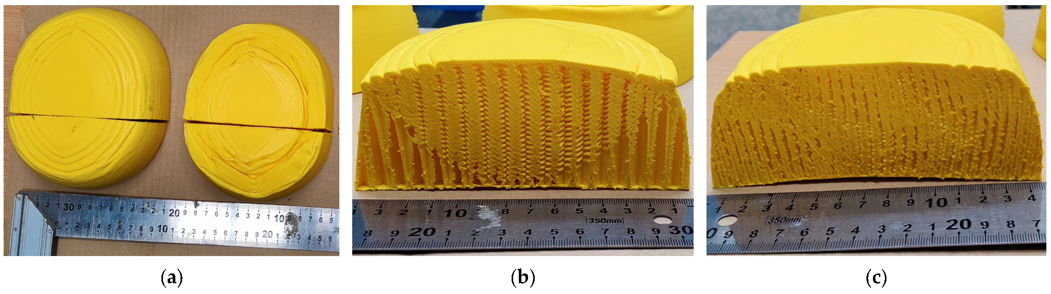
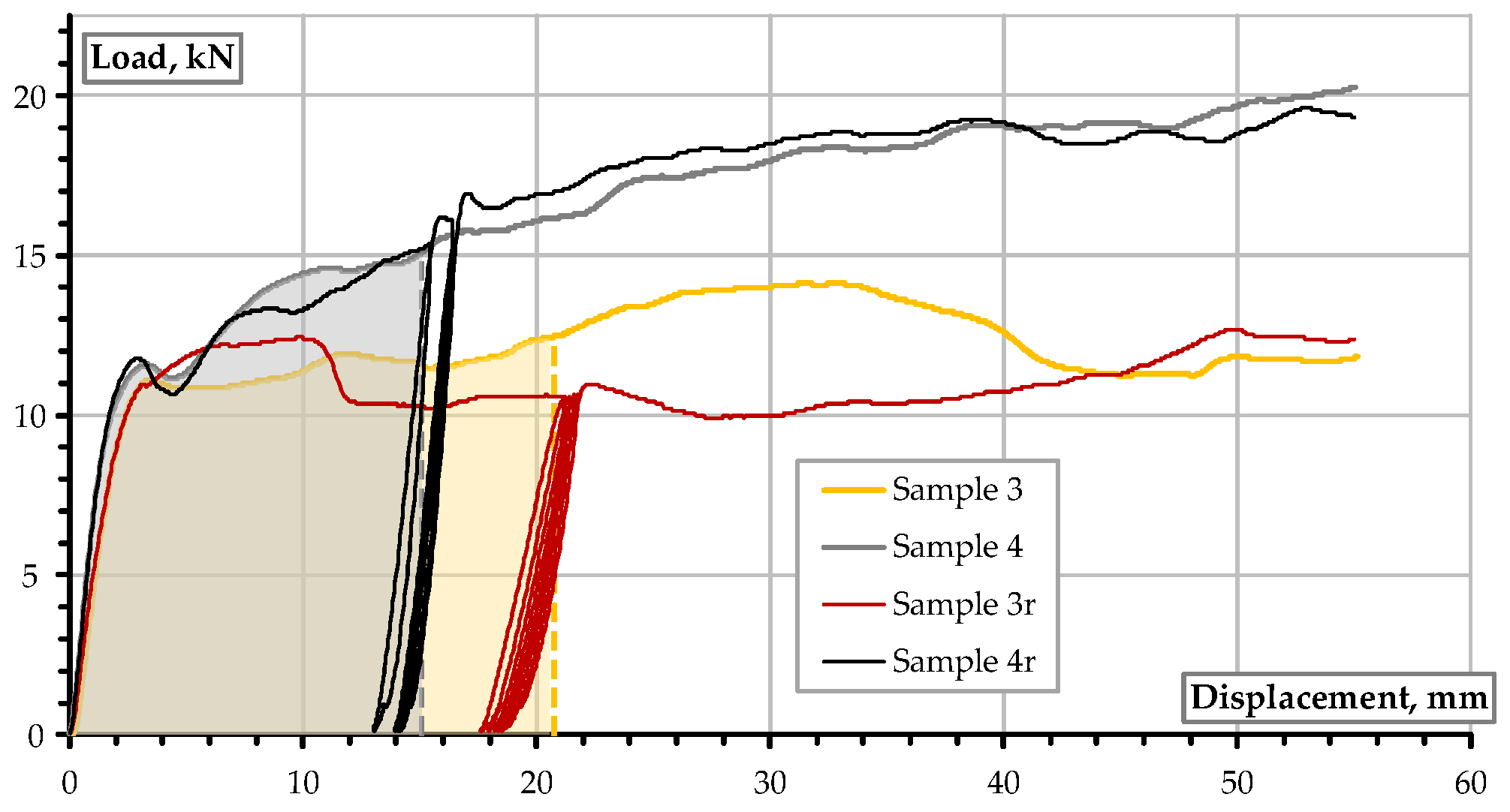
2.3.2. Monotonic and Repeated Tests of Modified Prototypes

This section develops Samples 3 and 4 (Figure 4e,f) to replicate the impact energy capacity of Sample 2 (Figure 7b) and ensure the reference weight of the front part of the fuselage prototype. The modification aims to improve the internal prototype structure, and the internal pattern of Sample 2 serves as the reference. Therefore, a cylindrical core with the same structure as Sample 2 (Figure 8c) served as the load-bearing core of both alternative specimens considered in this section, and the remaining internal volume had a sparse structure, ensuring the reference weight of the prototype remained consistent. This analysis employed the same 3D printing settings and LW-PLA Sample 2 (Table 3).
Following the above approach, the top surface shape, extruded vertically, formed the internal stiff cylinder. The analysis of the deformed shape of the internal lattice structure of Sample 1 (Figure 8b) determines the shape of the cylindrical stiffener of Sample 4. Thus, Sample 4 utilizes a 43 mm diameter cylindrical stiffener, localized at the center of the top surface of the prototype. Similar to the preliminary tests, this analysis utilizes SOLIDWORKS software (Educational Edition 2023 SP2.1, DASSAULT SYSTÈMES, Vélizy-Villacoublay, France) to create the fuselage front fragments. Figure 4e,f show the numerical models transformed using BAMBU STUDIO software (BAMBU LAB, Version 1.10.1.50, Shenzhen, China) for fabrication via FFF, and Table 3 summarizes the corresponding printing parameters and the resultant weights of the manufactured prototypes. The outer structure was produced with a 13% grid infill, while the inner core featured a denser 24% grid infill to enhance the load-bearing capacity. Two specimens of each prototype type were produced to compare their mechanical resistance under monotonic compression and repeated loads.
Figure 9 compares the compression test results of all prototype types subjected to the monotonic compression load. Analogously to Figure 7, these diagrams demonstrate the experimentally estimated load–displacement diagrams and the same graphs, indicating the 300 J deformation-energy-equivalent areas.
Both the modified prototypes (Samples 3 and 4 in Figure 9b) showed an improvement in energy absorption capacity compared with Sample 1, and the deformation required to absorb the impact energy of the modified prototypes approached the targeted results of Sample 2. To assess the reliability of the results from the modified specimens, this study employed repeated loading tests, which evaluate the rigidity changes of polymeric structures under various environmental conditions [42].
Figure 10 shows the test results of prototype Samples 3 and 4 under monotonic and repeated compression loading conditions. In this figure, the letter “r” in the sample notation reflects the repeated loading. All other sample parameters were identical for the same prototype type. The repeated loading followed the same protocol for both specimens. In the first stage, the specimen was loaded to achieve deformation corresponding to 300 J of energy absorption. The vertical dashed lines in Figure 10 indicate this deformation. After that, the samples were unloaded to a minor load (not zero) to prevent the sudden release of the test equipment, which is typical for such tests [42]. This release was followed by the loading repetition reaching the same compression load that was measured in the first loading stage. This loading produced a single loop. Both test specimens (Samples 3r and 4r) underwent five such loops. After that, the monotonic test was continued to estimate the residual resistance of the test specimens.
The monotonic and repeated loading tests employed the same test setup and equipment shown in Figure 5b. The loading was conducted under displacement control and at a loading velocity of 2.5 mm/min. The unloading was also conducted under displacement control at a loading velocity of 2.5 mm/min. However, the switch between load directions was manual, which explains some misalignment of the loading loops in Sample 4r, as shown in Figure 10. Figure 11 shows the deformed shapes of the internal structure of the modified prototypes. The cutting place corresponds to Figure 8a. The following section provides a detailed discussion of the test results.

3. Discussion of the Results

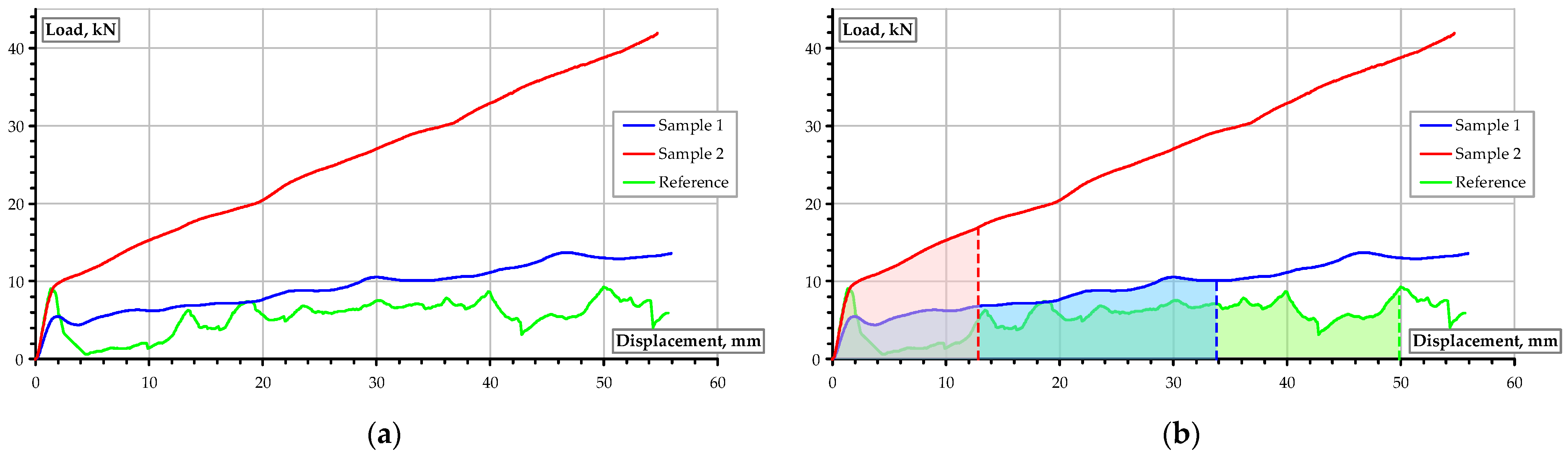
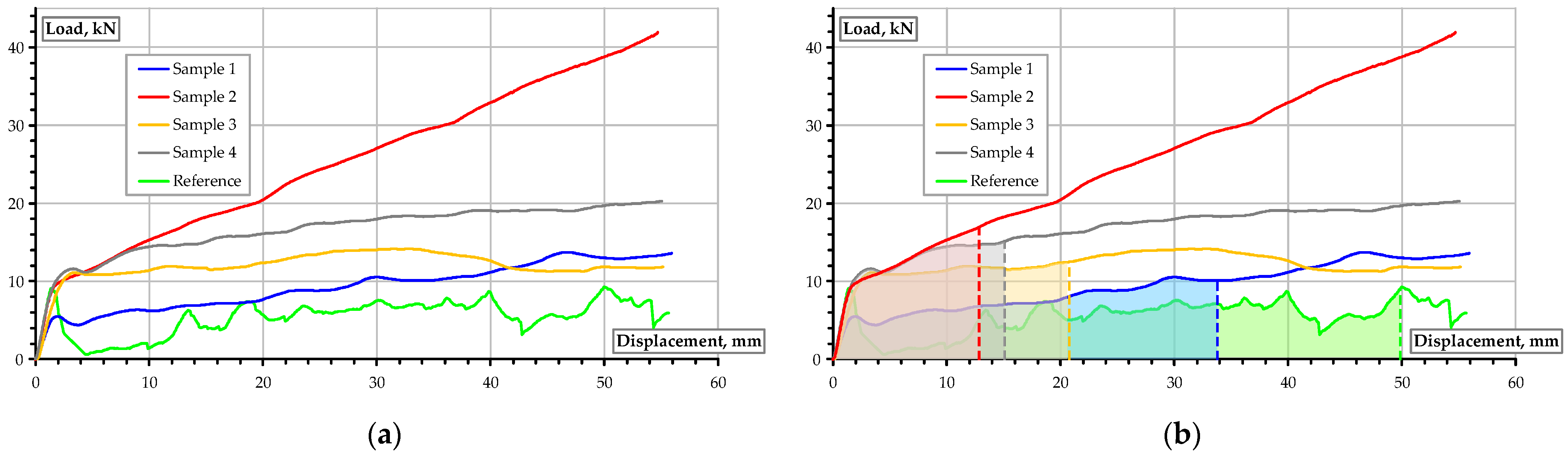
3.1. Deformation Energy Release

Figure 2a shows a typical result for the LW-PLA specimens compared with the PLA reference when a 100% infill density is considered. Normalizing the load-bearing capacity by sample weight improves the relative resistance of the LW specimens. Still, the relative resistance of the lightweight structure did not reach the PLA reference (Figure 2b). Moreover, the noticeable increase in the resistance of the LW-PLA samples occurred after exceeding the 10 mm deformation limit, which corresponds to 25% of their length. Such a deformation degree is barely attainable under service conditions. This outcome aligns with the results in the literature [7,13,43].
However, the need to create a relatively sparse lattice structure highlights the brittleness issues of the PLA material (Figure 6). Misiūnaitė et al. [34,35] provided several characteristic examples of brittle PLA failure under compressive loads. In this context, LW-PLA emerges as a promising alternative to enhance energy absorption in the lattice structures under strict weight limitations [14]. This study expands the DfAM concept by developing a lightweight metastructure capable of absorbing a deformation energy equivalent to that released during drone collisions (Section 2.2). Remarkably, the theoretical 300 J collision energy used in this study serves as a boundary condition to standardize the comparison of the deformation energy absorption values across different prototype configurations. It does not represent a realistic loading scenario but provides a consistent reference for evaluating the efficiency of internal structural modifications under quasi-static compression.
The analysis of the test results for Sample 3 (Figure 9b) reveals a 2.4-fold decrease in the compression deformation required to release the 300 J impact energy equivalent compared with the Reference sample. In particular, the Reference PLA prototype must reach a deformation of 49.9 mm to absorb the collision energy, whereas the modified Sample 3 can absorb this energy after deforming by 20.8 mm. At the same time, this modification also reduces the sample’s weight from 156.6 g of the reference to 144.0 g (Table 3).
The modified prototype (Sample 4) demonstrates an even more efficient outcome when the target energy absorption is reached after the 15.1 mm deformation, which is comparable to Sample 2 (12.8 mm), selected as the modification target; simultaneously, the prototype weight of these specimens was reduced from 289.0 g to 181.0 g (Table 3).
Figure 12 summarizes this discussion, presenting the normalized (by weight) load–displacement diagrams for all of the test specimens listed in Table 3. Notably, the compression deformation necessary to absorb the 300 J collision energy by the corresponding fuselage prototype limits these diagrams. Thus, a shorter diagram is preferred. Figure 12 reveals the following noticeable aspects:
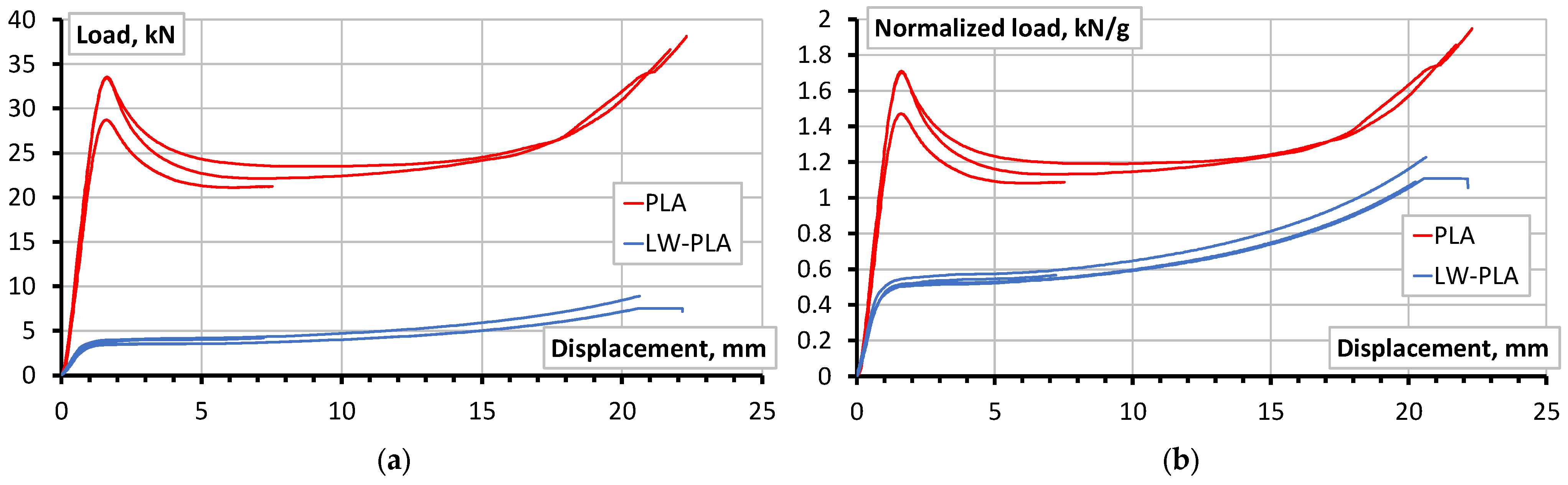
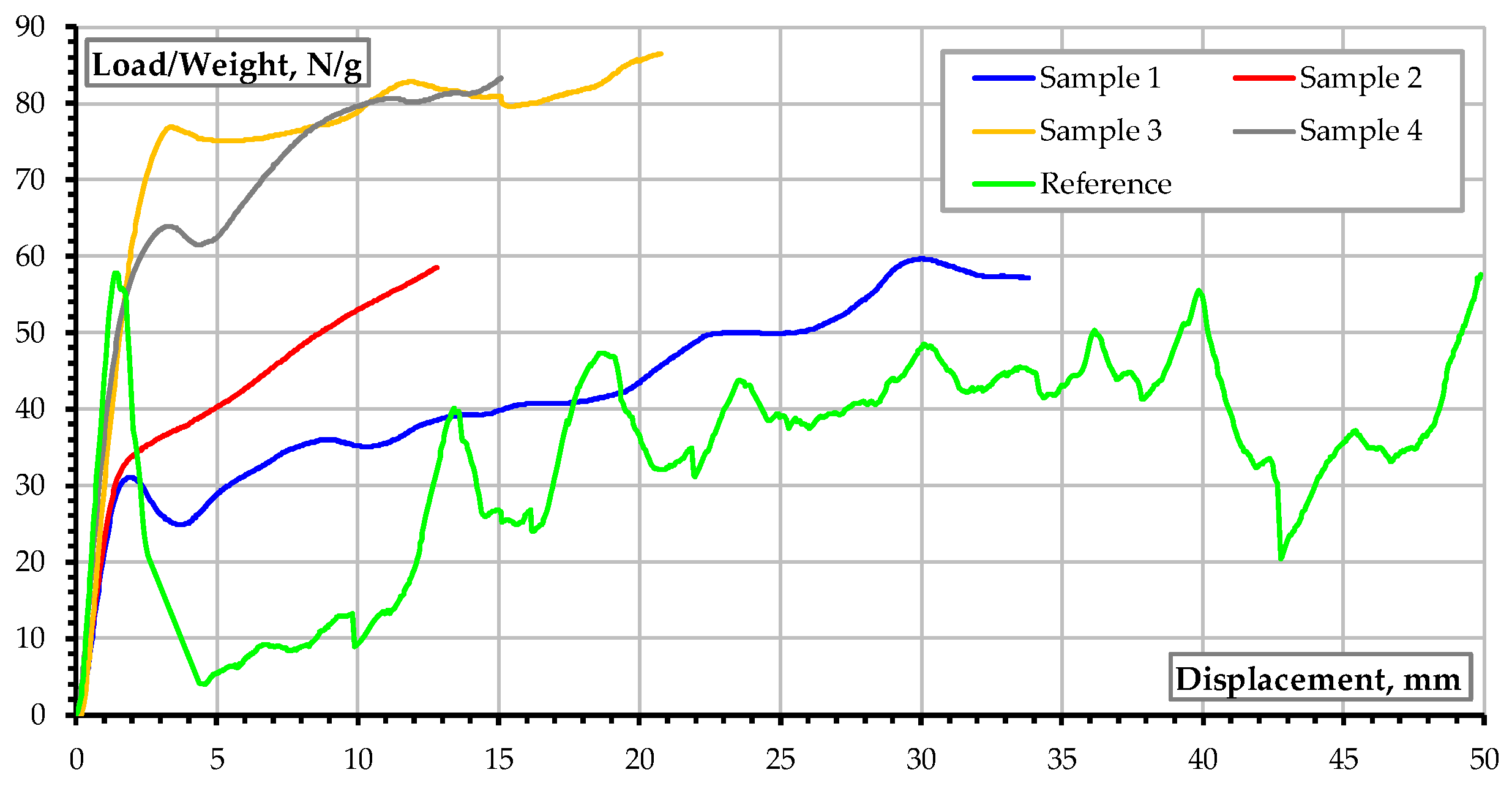
  • The reference PLA could reach a relatively high load-bearing capacity in the “elastic” stage. This stage is not elastic in the general context, as the prototype represents a lattice structure without a definite area and is characterized by a complex deformation pattern [13,34,44,45]. However, the structural resistance decreased suddenly after reaching its ultimate capacity, and the fracture of the internal lattice structure, along with a particular material consolidation, ensured further mechanical resistance. The resistance peaks and continuous increase in resistance (green diagram) reflect these mechanisms.
  • The alternative LW-PLA specimen (Sample 1) did not demonstrate exceptional performance, yielding a supremum diagram that approximates the resistance peaks of the reference diagram.
  • Sample 2 exhibits a similar relative resistance to Sample 1 during the “elastic” stage. This result is expected, as the weight (i.e., the infill density, but not its shape) determines a single difference between these specimens. Consequently, the normalized (blue and red) diagrams reflect this fact. After reaching the “elastic” limit, Sample 2 demonstrates a steeper increase in resistance than its counterpart (Sample 1) and serves as a useful intermediate benchmark for developing metastructural alternatives.
  • Both modified prototypes (Samples 3 and 4) demonstrated exceptional efficiency. Sample 4 released the deformation energy more efficiently than Sample 3; nonetheless, the latter specimen demonstrated a higher relative resistance.
The latter observation motivated the mechanical performance analysis of the modified prototypes under repeated loading conditions. Thus, Figure 10 shows that the mechanical responses of Samples 4 and 4r are almost identical, despite the appearance of load repetitions. The inclination of the reloading lines also corresponds to the “elastic” branch of the load–displacement diagrams, and the inclination angle is higher than observed in Sample 3r, revealing the near-elastic resistance of the fuselage prototype after repeated absorption of the collision energy equivalent. At the same time, the difference in the mechanical response of nominally identical Samples 3 and 3r reveals the less reliable deformation resistance mechanisms of this specimen type. Moreover, differences in the mechanical performance emerged before the load repetitions were applied. This observation relates the resistance alteration to the specimen’s structure, but not the loading conditions. Summarizing the results, Sample 3 had higher relative resistance but less stability under repeated loading, and Sample 4 achieved the best balance between weight and energy absorption. The following section examines the resistance mechanisms that contribute to the load-bearing capacity of the prototypes considered in this study.

3.2. Deformation Energy Absorption Mechanisms

The brittle nature of the lattice PLA structures controls the load-resistance mechanisms of the Reference sample (Figure 6b). The teeth-shaped diagram of the Reference specimen (green diagram in Figure 12) supports this inference, which also aligns with the results in the literature, as reported in [13,34,44,45], where the interested reader can find relevant details. Therefore, this discussion focuses on the results of the LW-PLA alternatives.
The concentration of internal damage in the top part of Sample 1 (Figure 8b) can explain the relatively low load-bearing capacity of this specimen (e.g., blue curve in Figure 12). In other words, the compression failure localized in the top zone of this sample (Figure 8b) does not ensure the activation of the entire lattice structure and raises the resultant deformability. The alternative, Sample 2, presents a similar picture (Figure 8c), where the bottom corners of the specimen do not exhibit severe damage. This observation reveals that not all of the internal structure parts were activated during the compression tests. In addition, the middle gap between the sample and the table reflects the deformation release of the specimen after removing the compression load, and the permanent compression effect is localized in the center part of the prototypes, as shown in Figure 8.
On the contrary, the modified metastructural prototypes (Figure 11) did not exhibit signs of uneven permanent deformation, with all of the failure concentrated in the center (strengthened) zone of the prototypes. However, Sample 3 shows a disordered failure pattern of the core structure (Figure 11a). This buckling-like failure can explain the alteration in the load–displacement diagrams for Samples 3 and 3r, as shown in Figure 10. In other words, an insufficient rigidity of the stiffening core does not prevent it from buckling, which can cause it to change shape and alter its structural performance. The modified Sample 4 did not demonstrate signs of buckling of the internal core (Figure 11b), which stabilized its deformations and ensured a robust structural configuration under repeated loads (Figure 10). This observation can form a governing design condition for the metastructures, where the structural core must ensure deformation stability. In this context, local buckling is preferred against the global buckling characteristic of Sample 3 (Figure 11a). Future DfAM strategies must prioritize core stabilization and a uniform energy distribution to achieve optimal performance.

3.3. Analysis Limitations and Further Research

The analyzed case represents a simplified example with arbitrarily set loading conditions, as the theoretical 300 J of energy served as an artificial benchmark for comparison purposes. Real-world impacts would likely lead to stiffer responses from the tested prototypes. The assumed deformation energy ensured a comparison of the mechanical resistance values of the tested prototypes, as shown in Figure 9b, Figure 10, and Figure 12. These test specimens demonstrated distinct deformation resistance values and cannot be compared without introducing a more or less realistic deformation limit. At the same time, the mechanical test results (Figure 9 and Figure 10) do not reflect the loads of real collision scenarios. Therefore, future studies must use drop-weight or dynamic tests for UAV design purposes. However, these tests are not essential for the current comparative framework, which emphasizes illustrating the efficient deformation energy absorption by LW-PLA metastructures. The core message of this analysis pertains to the comparison conditions, and the deformation energy can function as a reliable measure to evaluate the efficiency of the FFF structures. In this scenario, the front collision at the drone’s cruise speed determines the analysis benchmark. The support conditions of the fuselage prototypes are also hypothetically simplified. Real-world situations may involve various constraints that will affect the design output; however, the generalized design steps presented in this manuscript will remain unchanged.
This study incorporates heuristic optimization procedures to focus the analysis on the design steps and characterization processes of the materials. However, further research should incorporate advanced optimization algorithms, as considered in reference [43], to ensure a multi-objective solution that accounts for realistic constraints.
While this study successfully demonstrates the feasibility of using LW-PLA in drone fuselage components, several additional limitations merit attention. First, the study does not examine the fatigue behavior of the materials under cyclic loading, which is critical for drones subjected to repeated takeoffs, landings, and in-flight vibrations [2]. Second, the interaction between the printed parts and other drone components (e.g., electronics, fasteners, and adhesives) was not considered, which may impact integration and long-term reliability. Third, the scalability of the proposed DfAM approach to larger drones or more complex geometries remains untested.
Environmental conditions also influence the performance of polymeric materials [42,46,47], which compromises their mechanical resistance and energy absorption capabilities. In drone applications, temperature and humidity conditions establish key constraints on the mechanical resistance and durability of polymeric materials [2,47]. However, extending the DfAM design methodology may necessitate additional mechanical characterization means and conditions.
Future research should also explore the anisotropic behavior of LW-PLA under multi-axial stress states, as well as the impact of print orientation on crashworthiness. Moreover, integrating sensor-embedded structures, such as those in [33,47], could create new opportunities for real-time structural health monitoring in drones.

4. Conclusions

This study demonstrated the feasibility of using LW-PLA in drone fuselage components to enhance energy absorption during deformation while maintaining a weight limitation. By applying a design-for-additive-manufacturing (DfAM) approach, we developed metastructures that strategically combine different density zones to satisfy both mechanical and mass constraints. This research resulted in the following key findings:
  • Material efficiency: The stiffening core of the LW-PLA metastructure enabled a weight reduction of up to 62.6% while still achieving adequate energy absorption for non-critical drone components.
  • Structural optimization: The modified prototypes, featuring hybrid internal structures (notably the sample where internal buckling of the stiffening core was eliminated), exhibited superior performance under both monotonic and repeated loads, underscoring the significance of core stabilization and internal buckling control.
  • Comparative framework: The use of a theoretical deformation energy benchmark (300 J) provided a practical and consistent method for evaluating structural efficiency. However, it does not capture real-world design limitations. Therefore, future research should explore dynamic (impact) testing, the fatigue behavior of materials, and integration with drone systems in realistic environmental conditions.
  • Design implications: The experimental findings and design insights suggest utilizing lightweight, consumer-grade polymeric materials and desktop printers for drone prototyping. This approach could lead to broader adoption in academic and hobbyist settings. Additionally, further studies should incorporate sophisticated algorithms to achieve a multi-objective optimization solution.

Author Contributions

Conceptualization, V.G. and D.R.; methodology, V.G. and A.R. (Arvydas Rimkus); software, A.R. (Artūras Rasinskis); validation, V.G., Š.S. and D.R.; formal analysis, V.G.; investigation, A.R. (Arvydas Rimkus) and A.R. (Artūras Rasinskis); resources, Š.S.; data curation, A.R. (Artūras Rasinskis); writing—original draft preparation, A.R. (Artūras Rasinskis); writing—review and editing, V.G.; visualization, A.R. (Arvydas Rimkus) and A.R. (Artūras Rasinskis); supervision, V.G.; project administration, Š.S.; funding acquisition, Š.S. All authors have read and agreed to the published version of the manuscript.

Funding

This research work received funding from the project “Civil Engineering Research Centre” (agreement no. S-A-UEI-23-5, ŠMSM).

Institutional Review Board Statement

Not applicable.

Informed Consent Statement

Not applicable.

Data Availability Statement

The original contributions presented in the study are included in the article, further inquiries can be directed to the corresponding author.

Conflicts of Interest

The authors declare that they have no conflicts of interest.

References

  1. Zhou, L.; Miller, J.; Vezza, J.; Mayster, M.; Raffay, M.; Justice, Q.; Al Tamimi, Z.; Hansotte, G.; Sunkara, L.D.; Bernat, J. Additive manufacturing: A comprehensive review. Sensors 2024, 24, 2668. [Google Scholar] [CrossRef] [PubMed]
  2. Khan, N.; Riccio, A. A systematic review of design for additive manufacturing of aerospace lattice structures: Current trends and future directions. Prog. Aerosp. Sci. 2024, 149, 101021. [Google Scholar] [CrossRef]
  3. Whyte, D.J.; Doeven, E.H.; Sutti, A.; Kouzani, A.Z.; Adams, S.D. Volumetric additive manufacturing: A new frontier in layer-less 3D printing. Addit. Manuf. 2024, 84, 104094. [Google Scholar] [CrossRef]
  4. Ramos, A.; Angel, V.G.; Siqueiros, M.; Sahagun, T.; Gonzalez, L.; Ballesteros, R. Reviewing additive manufacturing techniques: Material trends and weight optimization possibilities through innovative printing patterns. Materials 2025, 18, 1377. [Google Scholar] [CrossRef] [PubMed]
  5. Hamza, A.; Bousnina, K.; Dridi, I.; Ben Yahia, N. Revolutionizing automotive design: The impact of additive manufacturing. Vehicles 2025, 7, 24. [Google Scholar] [CrossRef]
  6. İncesu, R.; Akderya, T. The influence of printing speed and temperature on the mechanical, absorptive, and morphological properties of PLA-based hybrid materials produced with an FDM-type 3D printer. Polymers 2024, 16, 2771. [Google Scholar] [CrossRef]
  7. Islam, M.A.; Mobarak, M.H.; Rimon, M.I.H.; Al Mahmud, M.Z.; Ghosh, J.; Ahmed, M.M.S.; Hossain, N. Additive manufacturing in polymer research: Advances, synthesis, and applications. Polym. Test. 2024, 132, 108364. [Google Scholar] [CrossRef]
  8. Beníček, L.; Vašina, M.; Hrbáček, P. Influence of 3D printing conditions on physical–mechanical properties of polymer materials. Polymers 2025, 17, 43. [Google Scholar] [CrossRef]
  9. Djokikj, J.; Tuteski, O.; Doncheva, E.; Hadjieva, B. Experimental investigation on mechanical properties of FFF parts using different materials. Procedia Struct. Integr. 2022, 41, 670–679. [Google Scholar] [CrossRef]
  10. Graba, M.; Grycz, A. Assessment of the mechanical properties of selected PLA filaments used in the UAV project. Materials 2023, 16, 1194. [Google Scholar] [CrossRef]
  11. MAXFILAMENT. 3D Printing Materials for Drone Production—What to Choose and Why? Available online: https://maxfilament.com/blog/3d-printing-materials-for-drones?utm_source=chatgpt.com (accessed on 11 May 2025).
  12. Šostakaitė, L.; Šapranauskas, E.; Rudinskas, D.; Rimkus, A.; Gribniak, V. Investigating additive manufacturing possibilities for an unmanned aerial vehicle with polymeric materials. Polymers 2024, 16, 2600. [Google Scholar] [CrossRef]
  13. Park, Y.; Lee, S. Characterization of PLA/LW-PLA composite materials manufactured by dual-nozzle FDM 3D-printing processes. Polymers 2024, 16, 2852. [Google Scholar] [CrossRef] [PubMed]
  14. Vălean, C.; Marșavina, L.; Linul, E. Compressive behavior of additively manufactured lightweight structures: Infill density optimization based on energy absorption diagrams. J. Mater. Res. Technol. 2024, 33, 4952–4967. [Google Scholar] [CrossRef]
  15. Jimenez-Martinez, M.; Varela-Soriano, J.; Martinez-Trinidad, J.; Alfaro-Ponce, M.; Coca-Gonzalez, M. Enhancing energy absorption in printed PLA components through post-processing and topological optimization. Results Eng. 2025, 26, 104972. [Google Scholar] [CrossRef]
  16. Vedrtnam, A.; Negi, H.; Kalauni, K. Materials and energy-centric life cycle assessment for drones: A review. J. Compos. Sci. 2025, 9, 169. [Google Scholar] [CrossRef]
  17. Egan, P.F. Design for additive manufacturing: Recent innovations and future directions. Designs 2023, 7, 83. [Google Scholar] [CrossRef]
  18. Dash, S.; Nordin, A.; Johansson, G. Dual design for additive manufacturing in engineering design: A systematic literature review. Rapid Prototyp. J. 2025, 31, 40–61. [Google Scholar] [CrossRef]
  19. Moreno-Núñez, B.A.; Treviño-Quintanilla, C.D.; Esponiza-Garcia, J.C.; Uribe-Lam, E.; Cuan-Urquizo, E. Effect of printing parameters on the internal geometry of products manufactured by fused filament fabrication (FFF). In Proceedings of the 34th Annual International Solid Freeform Fabrication Symposium—An Additive Manufacturing Conference, Austin, TX, USA, 14–16 August 2023; p. 15. [Google Scholar] [CrossRef]
  20. Arunkumar, P.; Balaji, D.; Radhika, N.; Rajeshkumar, L.; Mavinkere Rangappa, S.; Siengchin, S. Effect of infill pattern on mechanical properties of 3D printed PLA-Zn composites for drone frame structures: A topology optimization integrated application study. Results Eng. 2025, 25, 104107. [Google Scholar] [CrossRef]
  21. Rizzo, D.; Epasto, G.; Detry, A.L.H.S.; Landolfi, L.; Papa, I.; Squillace, A. Mono-material sandwich structures design produced by foam additive manufacturing: Study of performances under dynamic conditions. Prog. Addit. Manuf. 2025, 1–18. [Google Scholar] [CrossRef]
  22. Desole, M.P.; Gisario, A.; Barletta, M. Energy absorption of PLA-based metamaterials manufactured by material extrusion: Dynamic loads and shape recovery. Int. J. Adv. Manuf. Technol. 2024, 132, 1697–1722. [Google Scholar] [CrossRef]
  23. Simões, S. High-performance advanced composites in multifunctional material design: State of the art, challenges, and future directions. Materials 2024, 17, 5997. [Google Scholar] [CrossRef]
  24. Azevedo Vasconcelos, A.C.; Schott, D.; Jovanova, J. Hybrid mechanical metamaterials: Advances of multi-functional mechanical metamaterials with simultaneous static and dynamic properties. Heliyon 2025, 11, e41985. [Google Scholar] [CrossRef] [PubMed]
  25. Zhang, P.; Biligetu; Qi, D.; Xue, R.; Liu, K.; Huang, Z.; Wu, W.; Li, Y. Mechanical design and energy absorption of 3D novel hybrid lattice metamaterials. Sci. China Technol. Sci. 2021, 64, 2220–2228. [Google Scholar] [CrossRef]
  26. Kedziora, S.; Decker, T.; Museyibov, E. Application of functionally graded shell lattice as infill in additive manufacturing. Materials 2023, 16, 4401. [Google Scholar] [CrossRef] [PubMed]
  27. Hertlein, N.; Vemaganti, K.; Anand, S. Design optimization of lattice structures under impact loading for additive manufacturing. J. Mech. Des. 2024, 146, 111701. [Google Scholar] [CrossRef]
  28. Ramírez-Gil, F.J.; Silva, E.C.N.; Montealegre-Rubio, W. Design of topology-optimized functionally graded porous structures under transient loads. Int. J. Mech. Sci. 2024, 284, 109732. [Google Scholar] [CrossRef]
  29. Nia, A.B.; Nejad, A.F.; Li, X.; Ayob, A.; Yahya, M.Y. Energy absorption assessment of conical composite structures subjected to quasi-static loading through optimization based method. Mech. Ind. 2020, 21, 113. [Google Scholar] [CrossRef]
  30. Shinde, M.; Ramirez-Chavez, I.E.; Anderson, D.; Fait, J.; Jarrett, M.; Bhate, D. Towards an ideal energy absorber: Relating failure mechanisms and energy absorption metrics in additively manufactured AlSi10Mg cellular structures under quasistatic compression. J. Manuf. Mater. Process. 2022, 6, 140. [Google Scholar] [CrossRef]
  31. Song, J.; Zhao, K.; Liu, Y. Survey on mission planning of multiple unmanned aerial vehicles. Aerospace 2023, 10, 208. [Google Scholar] [CrossRef]
  32. Plamadiala, I.; Croitoru, C.; Pop, M.A.; Roata, I.C. Enhancing polylactic acid (PLA) performance: A review of additives in fused deposition modelling (FDM) filaments. Polymers 2025, 17, 191. [Google Scholar] [CrossRef]
  33. Kantaros, A.; Drosos, C.; Papoutsidakis, M.; Pallis, E.; Ganetsos, T. Composite filament materials for 3D-printed drone parts: Advancements in mechanical strength, weight optimization and embedded electronics. Materials 2025, 18, 2465. [Google Scholar] [CrossRef] [PubMed]
  34. Misiunaite, I.; Rimkus, A.; Gribniak, V. Developing lightweight steel profile and lattice polymeric core composite for structural use. Thin-Walled Struct. 2025, 206, 112697. [Google Scholar] [CrossRef]
  35. Misiūnaitė, I.; Rimkus, A.; Gribniak, V. Developing a lightweight hybrid profile concept with a steel shell and polymeric lattice core for optimal mechanical performance. Compos. Struct. 2024, 340, 118169. [Google Scholar] [CrossRef]
  36. Rimkus, A.; Farh, M.M.; Gribniak, V. Continuously reinforced polymeric composite for additive manufacturing—Development and efficiency analysis. Polymers 2022, 14, 3471. [Google Scholar] [CrossRef]
  37. ColorFabb. Technical Datasheet PLA Economy, v2.0; ColorFabb: Belfeld, The Netherlands, 2023; 3p. [Google Scholar]
  38. ColorFabb. Technical Datasheet Light Weight PLA (LW-PLA), v1.0; ColorFabb: Belfeld, The Netherlands, 2023; 3p. [Google Scholar]
  39. Aerofly Hobbies. Skywalker X8 Flying Wing 2120mm FPV/UAV Airplane Kit. Available online: https://www.aeroflyhobbies.com (accessed on 29 May 2025).
  40. RMRCX. UAV Talon PNP EPO 1718 mm Wingspan V-tail FPV Plane Aircraft. Available online: https://www.readymaderc.com/products/details/xuav-talon-pnp (accessed on 29 May 2025).
  41. Horizon Hobby. Opterra 2 m Wing BNF Basic with AS3X and SAFE Select. Available online: https://www.horizonhobby.com/product/opterra-2m-wing-bnf-basic-with-as3x-and-safe-select/EFL111500.html (accessed on 29 May 2025).
  42. Gribniak, V.; Sultani, H.A.; Rimkus, A.; Boris, R.; Sokolov, A.; Torres, L. Quantifying the flexural stiffness changes in the concrete beams with externally bonded carbon fiber sheets under elevated environment temperature. Alex. Eng. J. 2024, 104, 688–700. [Google Scholar] [CrossRef]
  43. Dogan, O.; Kamer, M.S.; Sahan, M.F. Multi-objective optimization of low-velocity impact and compression behavior of 3D-printed PLA cubic samples. Polymers 2025, 17, 627. [Google Scholar] [CrossRef]
  44. Arias-Blanco, A.; Álvarez-Blanco, M.; Belda, R.; Marco, M. Estimation and validation of elastic constants in fused filament fabrication 3D printing: From mesoscale to macroscale. Mater. Des. 2024, 246, 113329. [Google Scholar] [CrossRef]
  45. Sestini, M.; Puppi, D.; Braccini, S.; Macchi, T.; Matungano, B.; Macolic, S.; Guazzini, T.; Parrini, G.; Milazzo, M.; Danti, S. Elasticity in porous 3D-printed polylactic acid scaffolds for biomedical applications: A predictive approach. Polymers 2025, 17, 836. [Google Scholar] [CrossRef]
  46. Zhang, X.; Yin, Z.; Xiang, S.; Yan, H.; Tian, H. Degradation of polymer materials in the environment and its impact on the health of experimental animals: A review. Polymers 2024, 16, 2807. [Google Scholar] [CrossRef]
  47. Malikėnaitė, G.; Rimkus, A.; Rudinskas, D.; Jukna, A.; Gribniak, V. Additive manufacturing of conductive pathways for drone electrical equipment. Polymers 2025, 17, 1452. [Google Scholar] [CrossRef]
Figure 1. The compression test specimens: (a,b) sliced model and internal fabrication pattern; (c) test setup; (d) test samples after the tests.
Applsci 15 07164 g001
Figure 2. The compression test results: (a) load–displacement diagrams; (b) normalized load–displacement diagrams.
Applsci 15 07164 g002
Figure 3. The OPTERRA 2M WING prototype: (a) front part for prototyping; (b) schematic dimensions in mm.
Applsci 15 07164 g003
Figure 4. Fuselage front fragment models prepared for the FFF: (a,b) reference PLA model and its internal pattern; (cf) internal patterns of LW-PLA Samples 1, 2, 3, and 4 (refer to Table 3 for the sample notations).
Applsci 15 07164 g004
Figure 5. The fuselage prototypes: (a) specimens prepared for the test; (b) test setup.
Applsci 15 07164 g005
Figure 6. The first test results of the fuselage prototypes: (a) deformed shapes of Samples 1 and 2 and the reference specimens; (b) fragmentation view of the Reference prototype (refer to Table 3 for the sample notations).
Applsci 15 07164 g006
Figure 7. Load–vertical displacement diagrams of the tested prototypes: (a) test results; (b) the shaded deformation energy areas corresponding to the 300 J impact energy equivalent (refer to Table 3 for the sample notations).
Applsci 15 07164 g007
Figure 8. Internal structure analysis of the LW-PLA prototypes: (a) cutting place; (b) Sample 1; (c) Sample 2.
Applsci 15 07164 g008
Figure 9. Load–vertical displacement diagrams of the tested prototypes: (a) test results; (b) indicated deformation energy areas corresponding to the 300 J impact energy (refer to Table 3 for the sample notations).
Applsci 15 07164 g009
Figure 10. Compressive test results for the modified prototypes under monotonic and repeated loads.
Applsci 15 07164 g010
Figure 11. The deformed internal structure of the modified prototypes: (a) Sample 3; (b) Sample 4.
Applsci 15 07164 g011
Figure 12. Compressive test results of the modified prototypes after normalization.
Applsci 15 07164 g012
Table 1. Current research trends in AM for drone applications.
CategoryFocus AreaGaps IdentifiedRef.
MaterialsPLA, ABS, LW-PLA, PA6, PC, PETG *Lack of performance knowledge of LW materials[6,9,10,11,12,13,14,15]
Optimizing mechanical performanceStress–strain behavior, energy absorption, and failure mechanismsLack of real-world collision/impact analysis[9,11,14,15,16]
Design issues (DfAM)Internal structure, infill patterns, and lattice designLack of standardized DfAM frameworks for drones[2,14,17,18,19,20]
Weight reductionFoam cores, porous plastics, and internal structure optimizationMechanical compromise and fabrication repeatability issues[6,11,12,13,14,21]
Hybrid materials and structuresIntegral structures and materials’ compatibilityFew holistic studies integrating geometry and materials[6,13,22]
* PLA = polylactic acid; ABS = acrylonitrile butadiene styrene; LW = lightweight; PA6 = polyamide 6; PC = polycarbonate; PETG = polyethylene terephthalate glycol.
Table 2. Physical characteristics of polymeric materials [37,38].
MaterialE [GPa]ft [MPa]εu [%]Tg [°C]Tm [°C]
xyzxyzxyz
PLA3.303.3570713.53.555–60150–160
LW-PLA3.35 (0.86) *43 (10) *8.1 (12.8) *55–60150–160
* The characteristics correspond to an FFF nozzle temperature of 200 °C or 250 °C; the latter values are presented in the brackets.
Table 3. Fabrication settings of the fuselage prototypes.
ParametersReferenceSample 1Sample 2Sample 3Sample 4
MaterialPLALW-PLALW-PLALW-PLALW-PLA
Extruder temperature, °C220230230230230
Print bed temperature, °C5555555555
Volumetric speed, mm3/s205555
Flow ratio, %9853535353
Infill ratio, %4.0132413/2413/24
Infill patternGridGridGridGridGrid
Resultant weight, g156.5176.5289.0144.0181.0
Disclaimer/Publisher’s Note: The statements, opinions and data contained in all publications are solely those of the individual author(s) and contributor(s) and not of MDPI and/or the editor(s). MDPI and/or the editor(s) disclaim responsibility for any injury to people or property resulting from any ideas, methods, instructions or products referred to in the content.

