1. Introduction
With the rapid development of unmanned aerial vehicle (UAV) technology, quadrotors show broad application prospects in military and civil fields. In the military field [
1,
2], quadrotors are widely used in reconnaissance and surveillance, target localization, electronic countermeasures, and other tasks; in the civil field [
3,
4,
5], they play an increasingly important role in aerial photography, agriculture, logistics and delivery, emergency rescue, and other aspects.
However, the quadrotor is inherently a strongly coupled nonlinear system with underdriven characteristics. Since quadrotors usually work in complex outdoor environments, they are inevitably affected by a variety of disturbing factors, including signal noise [
6], bad weather [
7], and so on.
During mission execution, quadrotors often carry varying payloads to meet diverse requirements. As shown in
Figure 1, firefighting missions require water tanks, agricultural spraying demands pesticide containers, and logistics delivery involves transporting parcels. The payload variations significantly alter the mass parameters while inducing dynamic changes in the center of gravity and moment of inertia. These alterations affect dynamic characteristics and compromise trajectory tracking accuracy and attitude stability. Therefore, it is of great practical significance to study the stability control method of quadrotor UAVs under variable load conditions.
Recent years have witnessed significant advances in quadrotor control research, primarily encompassing conventional control methods [
8,
9,
10], modern control approaches [
11,
12], and intelligent control techniques [
13,
14]. variable-load quadrotors face control difficulties due to changing mass, shifting center of gravity, and external disturbances. Current studies primarily address these challenges through parameter adaptation and disturbance observation methods.
Regarding parameter adaptive control, the scholars of [
15] proposed a hybrid fuzzy sliding mode control method to ensure quadrotor stability, though its fuzzy rule processing requires considerable computation time. The study of [
16] proposed a mass estimation method using least squares and sliding mode observers. However, this solution only works for situations involving gradual mass reduction during payload release, which limits its practical use. In disturbance observation and compensation, the study of [
17] developed an extended state observer (ESO)-based control scheme for quadrotors carrying cable-suspended payloads, achieving effective swing reduction and improved disturbance resistance during lifting maneuvers.
Quadrotors possess constrained onboard computing capabilities as flight platforms. Their control algorithms must therefore maintain strict real-time performance while ensuring computational efficiency. This creates a critical challenge in quadrotor control: how to effectively reduce computational and communication loads while maintaining control performance. event-triggered control (ETC), as an innovative control method, has gained wide attention in the UAV field [
18,
19,
20]. event-triggered control offers distinct advantages through its unique triggering mechanism that enables seamless integration with various control methods, maintaining system stability while reducing computational and communication resource demands. The scholars of [
21] developed a switched-threshold event-triggered mechanism integrated with an ESO, enabling intermittent velocity/disturbance observation and precise estimation while establishing a disturbance-rejection output feedback control law for trajectory tracking with guaranteed Zeno-free operation.
Quadrotors may encounter various actuator failures during mission execution. Fault tolerant control [
22,
23,
24,
25] means that the closed-loop system remains stable and meets certain performance specifications in the event of the failure of a sensor, actuator or component of the control system. The research of [
26] proposes a real-time actuator fault detection and isolation (FDI) method for quadrotor UAVs using a linear parameter-varying model and directional residuals to balance fault sensitivity and disturbance robustness. The scholars of [
27] presented a fault-tolerant tracking control method for quadrotors, combining recursive least squares-based motor parameter identification, an augmented state observer, and nonlinear model predictive control (NMPC) to handle actuator faults and disturbances. The study of [
28] developed an output-feedback dynamic surface sliding mode passive fault-tolerant control method for quadrotors under actuator controllable failures, significantly enhancing system robustness against both faults and uncertainties.
Active disturbance rejection control (ADRC) has attracted significant attention due to its unique disturbance estimation and compensation mechanism. This innovative control strategy employs an ESO to achieve the real-time estimation and compensation of both internal and external disturbances [
29]. Compared with conventional control methods, ADRC demonstrates distinct advantages including model independence, strong robustness, and enhanced disturbance rejection capabilities.
Significant theoretical advancements were achieved in ADRC. Observer design evolved from the original nonlinear ESO to linear ESO [
30,
31], adaptive ESO [
32,
33], fuzzy ESO [
34,
35,
36], and neural network-based ESO [
37]. The innovations of control algorithm integrated ADRC with sliding mode control [
38], model predictive control [
39], and adaptive control [
40], creating hybrid strategies with improved dynamic performance and robustness. Meanwhile, intelligent parameter tuning techniques employing particle swarm optimization (PSO) [
41], grey wolf optimization [
42], and reinforcement learning [
43] enhanced the practicality of ADRC in engineering applications.
This study proposes an event-triggered ADRC for variable-load quadrotors with actuator failures, introducing PSO for online parameter tuning. This study makes the following key contributions:
A cascaded ADRC approach is developed by decoupling the system into position and velocity subsystems, each with dedicated ESOs and controllers. Combined with the event triggered mechanism, it effectively reduces the consumption of computing resources.
To address actuator failures, a fault-tolerant control method integrating prescribed performance functions with ADRC is proposed, which dynamically constrains tracking errors within predefined bounds through an error transformation mechanism.
The controller introduces PSO for online parameter adaptation, enhancing both system adaptability and robustness.
2. Modeling of Variable-Load Quadrotor
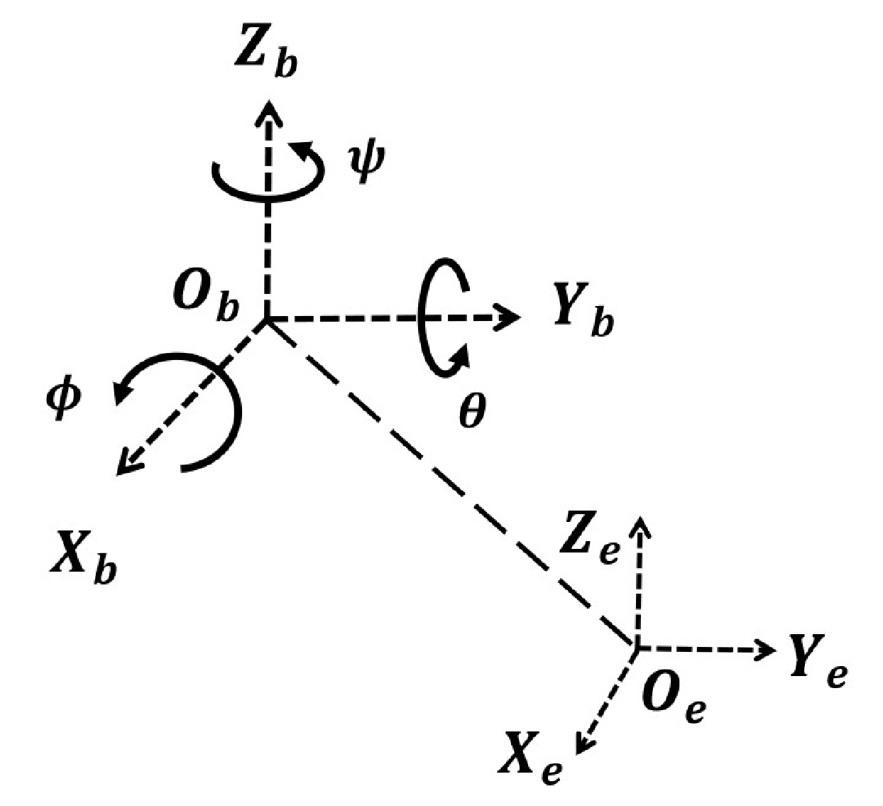
To accurately describe the motion state of the quadrotor UAV, two coordinate systems were established as shown in
Figure 2: the body coordinate frame
and the inertial coordinate frame
.
The system possesses six degrees of freedom containing both position coordinates
and attitude angles
. These Euler angles represent roll about
, pitch about
, and yaw about
axes, with counterclockwise rotation defined as positive. The rotation matrix
can be expressed as
where
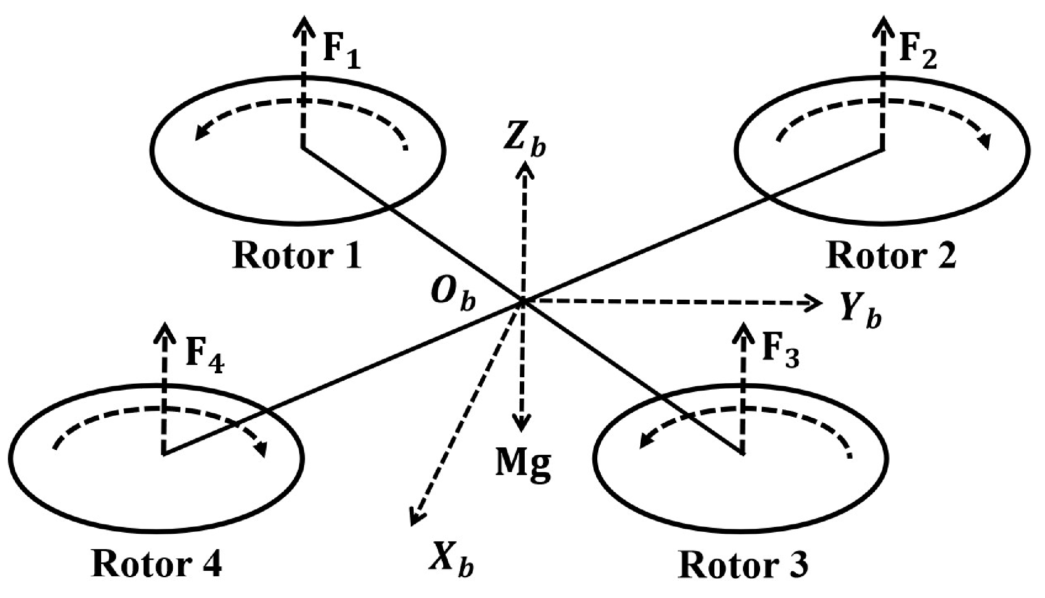
According to the cross structure of the frame, the quadrotor UAV could be categorized into the “+” type and “×” type. The model in this study was built based on the “×” type structure, which is shown in
Figure 3.
The following assumptions were made for modeling the dynamics:
Assumption 1. The airframe of quadrotor aircraft is typically constructed from lightweight yet rigid materials such as carbon fiber or aluminum alloy. Under normal operational loads, the elastic deformation of these structures can be considered negligible. The quadrotor is rigidly attached and exhibits no elastic deformation.
Assumption 2. Most quadrotors are symmetrically designed. The load-free quadrotor has a uniformly distributed mass, with its center of gravity aligned with the of the body frame.
Assumption 3. The variable payload is rigidly connected to the quadrotor.
Remark 1. The structural rigidity assumption may lose validity under extreme operational conditions, particularly when subjected to high-frequency vibrations, impact loads, or substantial deformations. Assumption 3 considered a rigid connection between the payload and the quadrotor airframe, with non-rigid coupling scenarios explicitly excluded. This modeling approach presents certain limitations.
Based on the physical structure of the quadrotor, it can be observed that the aircraft is primarily influenced by two forces: the lift forces generated by the four rotors and the gravity. The expression for gravitational force in the inertial frame is
where
M is the mass of the quadrotor body,
m is the mass of the load, and
g is the gravitational acceleration.
In the body coordinate system, the lift of the rotor can be expressed as
where
denotes the total lift of the rotor and
denotes the lift provided by a single rotor.
Combining Equations (
1) and (
3), the expression for lift in the inertial coordinate system can be obtained:
During flight, the air resistance experienced by a quadrotor is closely related to its flight velocity, which can be expressed as
where
is the air resistance coefficient. To simplify the analysis, the air resistance coefficient was set to be the same in all directions.
By treating the quadrotor UAV and its payload as a single rigid body, according to Newton’s law, the displacement dynamics of the variable-load quadrotor in the inertial coordinate system
E can be derived as
For the rotational dynamics of the quadrotor, the moment expression for the cross-configuration can be formulated as
where
l is the length of the rotor arm and
is the moment coefficient.
We set
as the rotational velocity in the body coordinate system. The shifting center of mass during flight transforms the quadrotor into an asymmetric structure, resulting in time-varying moment of inertia matrices. For a quadrotor with variable payload, its inertia matrix can be expressed as
where
,
, and
denote the offset distance between the center of gravity and the center of the body.
When the quadrotor maintains stable flight with minimal attitude variations, the Euler angle rates in the inertial frame can be approximated by the body-frame angular velocities:
. This linear approximation permits derivation of the quadrotor rotational dynamics through the Euler equations. The rotational dynamics of the quadrotor can be derived from Euler equations of motion as
The displacement Equation (
6) and rotational Equation (
9) collectively constitute the dynamic model of the variable-load quadrotor.
By introducing virtual control variables
,
,
,
into the control system, where
, and then combining Equations (
3) and (
7), the control inputs to the quadrotor can be obtained as
The control model of the variable-load quadrotor can be given as
The actuator system, comprising four electronic speed controllers (ESCs) with corresponding brushless motor–propeller assemblies, serves as the critical actuation core in quadrotor flight control. During operational missions, various actuator failures may occur due to mechanical wear, electronic component malfunctions, or external disturbances, which directly alter the dynamic characteristics of the quadrotor.
In quadrotor systems, actuator faults typically manifest as the following:
Loss of Effectiveness: Manifested as a decrease in motor thrust output efficiency; potential causes include insufficient power supply voltage, reduced ESC drive capability, or propeller damage.
Bias Fault: Characterized by a constant offset in motor output; potential causes include sensor zero drift or ESC calibration errors.
When the actuator has the above faults, the actual lift it provides can be written as
where
denotes the actual lift force generated by the actuator. The efficiency factor
represents the effectiveness of the actuator, while
indicates the bias factor. The system operates under the following conditions: when
and
, the quadrotor is in normal operation; when
and
, the quadrotor has loss of effectiveness in the actuator; and when
with
, a bias fault is present in the system.
According to Equations (
10) and (
12), the actual control inputs of the variable-load quadrotor in the case of actuator failure can be obtained as
Combining Equations (
6)–(
13), the dynamic model of the variable-load quadrotor with actuator faults can be obtained as
The inherent underactuation and strong dynamic coupling in quadrotor systems mean that any actuator fault propagates disturbances across all 6-degree-of-freedom motion states. When a fault occurs, the actual actuator lift force
is obtained through Equation (
12). Using Equation (
13), the total lift and individual moments under actuator fault conditions can be computed, which drive the flight through the dynamics model (
14).
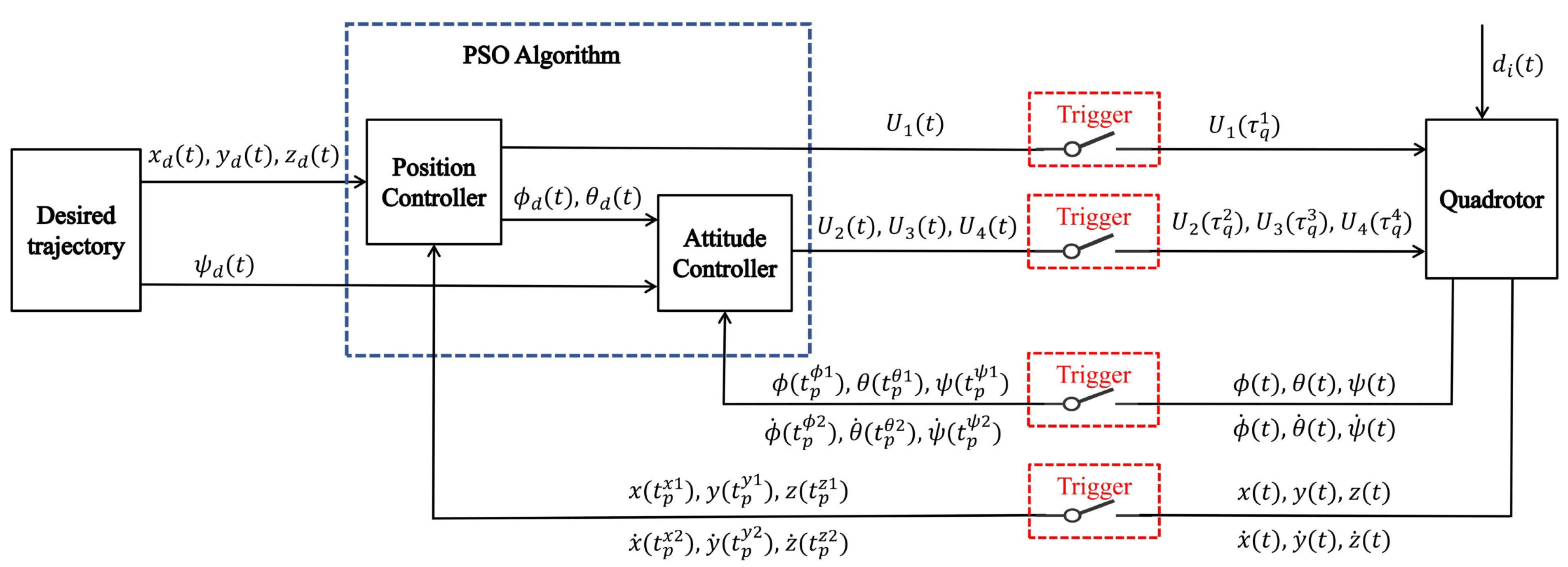
3. Design of Event-Triggered Cascade Active Disturbance Rejection Control with Prescribed Performance
The quadrotor represents an underactuated system with four inputs governing six degrees of freedom. This configuration inherently prevents complete decoupling within the system. Through a cascaded outer–inner loop structure, the controller achieves implicit decoupling between positional and attitudinal kinematic relationships. Displacement control along the x- and y-axes must be achieved through attitude angle regulation.
Based on this principle, we propose a dual-loop cascade active disturbance rejection control (CADRC) scheme with prescribed performance control (PPC). An event-triggered mechanism is introduced to reduce computational redundancy, while PSO is employed for online controller parameter self-tuning.
The control system structure is shown in
Figure 4. The outer-loop position controller generates the desired pitch angle
, roll angle
, and
, which are then passed to the inner-loop attitude controller for conversion into
,
, and
.
3.1. Prescribed Performance Function and Error Transformation
Actuator faults are considered part of the total disturbance in the ADRC framework. The ESO estimates and compensates for these faults along with other disturbances. To enhance the disturbance rejection capability while mitigating initial overshoot, prescribed performance functions are introduced to further optimize control performance.
Consider the altitude
z-channel as an example. A monotonically decreasing performance boundary function
is defined to constrain the transient tracking error
. The boundary function is
where
is the initial value of the prescribed performance function and
is the steady state value of the prescribed performance function,
. The
directly determines the ultimate precision of the system. The
is the rate factor for the speed of convergence, which determines how quickly the error boundary decays from its initial to steady-state value. A larger
accelerates convergence but may cause high-frequency oscillations. A smaller
produces smoother responses but extends transition time.
If the system error
is satisfied,
then the prescribed performance is satisfied. Here,
are the error boundary parameters to be designed. These parameters control the allowable range of tracking errors. A larger
permits greater instantaneous errors but may reduce steady-state accuracy. A smaller
imposes stricter error constraints but may increase control effort.
The constrained transient error
is transformed into an unconstrained error variable
through conversion mapping. The error transformation function is designed as follows:
where
is a smooth, strictly monotone decreasing function satisfying
. The expression for
is
We then define
, and, by calculating the inverse function of Equation (
18), one can obtain an expression for
as
The derivation of
leads to
where
.
3.2. Design of an Event-Triggered Cascade Active Disturbance Rejection Controller
The dual-loop control architecture comprises three sub-controllers in each loop: x-, y-, and z-axis controllers in the position loop and roll (), pitch (), and yaw () controllers in the attitude loop.
Due to the dynamic characteristics of the quadrotor, the sub-controllers are hierarchically organized into position and velocity controllers to construct a cascaded ADRC system. Taking the altitude
z channel as an example, the altitude channel dynamics described in model (
11) can be rewritten as
where
,
,
,
f represents the other parts in the modeling of the system, and
stands for the unmodeled parts of the system and disturbances outside the system.
Defining a new virtual control variable
, the dynamics expressed in Equation (
21) can be rewritten as
Position subsystem :
Velocity subsystem :
The cascade ADRC controller design consists of two steps:
- Step 1:
For subsystem
, the extended state can be written as
The ESO is designed as
where
(
) are estimates of the state variable
(
); the observer gains
(
) are designed to ensure that matrix
is Hurwitz. The variable
represents the sampled value of system state
at the event-triggered instant
, which serves as the state value for the current cycle. The event-triggered mechanism for this observer is designed as follows:
The observer trigger threshold
is designed as a fixed value. Based on the desired trajectory
, the virtual control variable
is designed as follows:
where
is the controller parameter to be tuned.
- Step 2:
For subsystem
, the extended state can be written as
The ESO is designed as
where
(
) is an estimate of the state variable
(
), and the observer gains
(
) are required to satisfy the matrix
, which is Hurwitz. The variable
represents the sampled value of system state
at the event-triggered instant
. The event-triggered mechanism for this observer is designed as follows:
where
is designed as a fixed value. Due to the event triggered mechanism, the trajectory tracking error for the
z channel is defined as
According to the virtual control variable
and tracking error, the virtual control variable
is designed as follows:
where
is the controller parameter to be tuned.
Remark 2. The cascaded structure decouples the system into two subsystems, enabling targeted disturbance rejection. The outer-loop ESO (23) estimates position-related disturbances, while the inner-loop ESO (27) handles velocity-level uncertainties. The dual-loop design enables optimal balance between transient response and noise suppression by adjusting bandwidth. It overcomes the inherent limitation of conventional single-ESO systems, which must find a compromise between dynamic performance and disturbance rejection. This approach ultimately improves the overall system robustness. The control design of the
x and
y channels in the position controller is similar to that of the
z channel. The sampled values of virtual control variables
,
, and
and yaw angle
at the event-triggered instant
are utilized to compute the desired roll/pitch angles and control command
.
The variables
, and
are calculated based on the sampled value of the control variable
at the event-triggered instant
. The controller event-triggered mechanism is designed to
where
denotes the threshold extremum factor and
represents the error sensitivity factor. The controller trigger threshold is designed as a time-varying value related to the error, and the trajectory estimation error
is introduced into the design.
Remark 3. This study integrates trajectory tracking error into the event-triggered mechanism of the controller, employing a time-varying threshold that dynamically adjusts according to error magnitude. As tracking error grows, the triggering threshold decreases while update frequency rises. Conversely, diminishing error leads to increased threshold values and reduced triggering frequency.
Remark 4. For the quadrotor with strongly coupled dynamics, trajectory tracking error should be computed comprehensively in the 3D space rather than independently. In the error equation (35), the controller cannot obtain the actual state values in real time due to the presence of event-triggered mechanisms. Therefore, the estimated state of the ESO is used for the calculation of the event-trigger mechanisms (24) and (28) and the trajectory tracking error. This design stems from two key considerations. First, subsequent proofs demonstrate that the estimation error is uniformly ultimately bounded, ensuring the estimated values effectively approximate the true states of the quadrotor. Second, the fundamental objective of event-triggered control lies in minimizing unnecessary computations and communications. Requiring real-time value computation within the controller event-triggered mechanism would contradict this design principle.
The attitude channel sub-controller of the inner loop controller is designed similarly to the position channel. Taking the roll channel as an example, the controller event-triggered mechanism for this channel is
Remark 5. This study employs a fixed threshold in the event-triggered mechanism of the observer while adopting a dynamic threshold in the controller. This clearly divided design ensures that the observer rapidly and stably estimates system states and disturbances, with the fixed threshold guaranteeing consistent response speed unaffected by dynamic parameters.
The controller utilizes a dynamic threshold to balance tracking error and computational overhead. This approach ensures adaptability to varying performance demands during different flight phases. The fixed threshold of the observer provides reliable estimated inputs for the controller, while the dynamic threshold of the controller further optimizes overall resource efficiency.
3.3. Cascade Active Disturbance Rejection Controller Based on Particle Swarm Optimization
Recognizing the critical influence of controller parameters on cascaded ADRC system performance, this study develops an online parameter self-tuning method based on PSO, which effectively enhances the adaptability and robustness of the control strategy.
Each cascade sub-controller has six parameters [
,
,
,
,
,
] to be tuned. Thus, the entire inner-loop attitude and outer-loop position control system has a total of 36 adjustable parameters. The bandwidth method helps simplify parameter tuning. This approach utilizes two important parameters: the observer bandwidth
and the controller bandwidth
. The parameters can then be systematically determined through the following bandwidth-based relationships:
within the attitude control loop, the three attitude controllers exhibit control objectives of similar magnitude. Likewise, the three position controllers in the displacement control loop maintain consistent scale. This means that identical parameter sets can be employed for each control loop.
The simplification process cuts the total tuning parameters from 36 down to 6. Among these, three parameters handle attitude control while the remaining three manage position control. This reduction maintains effective control performance. The parameters requiring adjustment consist of , and .
Remark 6. In the controller parameterization process of the quadrotor, the six sub-controllers function as a coupled system. The quadrotor exhibits strong inherent coupling between its displacement and rotational attitude. This interdependence limits how individual sub-controllers can be tuned. Consequently, the six sub-controllers cannot be parameterized completely independently. Consider the case where the yaw angle . If the attitude controller performs poorly, it may fail to generate adequate roll angle. This deficiency directly impairs tracking performance along the x-axis. In such cases, optimizing only the x-channel controller parameters fails to effectively improve tracking performance.
In PSO, each particle updates its position and velocity according to the following rules:
where
i denotes the
ith particle in the swarm,
denotes the velocity of the
ith particle at the
tth iteration,
denotes the position at the
tth iteration,
denotes the best position in the history of individual particles,
denotes the global best position,
w denotes the inertia weight,
and
denote acceleration constants, and
and
are random numbers between 0 and 1. By iteratively updating the particle positions and velocities, the PSO can achieve effective exploration of the solution space.
The inertia weight
w is an important parameter that determines the effect of inertia on the historical velocity of the particle when updating the velocity. A linearly decreasing inertia weighting strategy is introduced to dynamically adjust
w, which is updated as follows:
where
and
are the initial and final values of the inertia weights, respectively;
t denotes the current number of iterations; and
denotes the maximum number of iterations. The algorithm dynamically adjusts parameter
w through linear decrement, maintaining balance between global and local exploration throughout the optimization process.
The fitness function plays a crucial role in determining optimization results. It must properly evaluate particle quality to effectively guide the particle swarm’s search direction. Overly complex function designs may decrease iteration counts. However, the computational time required for these complex operations could lower overall efficiency. Therefore, the design of the fitness function needs to balance guidance and efficiency.
With the goal of trajectory tracking, the tracking error of the quadrotor on the target trajectory is crucial for evaluating the control performance. For a quadrotor system operating in three dimensions, the trajectory tracking error is defined as
In quadrotor flight control, attitude stability is as important as trajectory tracking accuracy. To quantitatively evaluate the degree of oscillation of the attitude angle, the standard deviation is used as a key indicator. Taking the roll angle
as an example, the standard deviation calculation expression is
where
n is the number of samples and
is the sample mean.
The designed fitness function is
where
a and
b are positive parameters and
,
, and
are the standard deviation of the roll, pitch, and yaw angles, respectively. In the design of this function, time is considered as the weight of the error. The function treats time as an error weighting variable, where increased duration enhances tracking error influence on fitness function. The fitness function output
Y inversely relates to controller performance. Lower
Y values correspond to better control effectiveness.
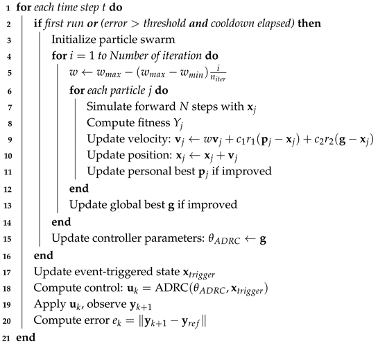
The algorithm integrating PSO for online parameter adaptation in cascade ADRC is shown in Algorithm 1.
| Algorithm 1: Cascade ADRC Based on PSO |
![Applsci 15 07021 i001]() |
To achieve online self-tuning of the PSO in the controller, an event-triggered mechanism is designed as follows:
where
denotes the trigger instant of parameter adaptation;
denotes the next trigger instant;
denotes the minimum trigger interval, equivalent to the cooling time; and
is the fixed threshold of the designed event trigger. The presence of a trigger interval avoids the Zeno phenomenon in the event-triggered mechanism.
Remark 7. The stable flight control of a quadrotor must meet trajectory tracking accuracy and attitude stability requirements. Simulation results demonstrate that omitting attitude angle constraints enables fast trajectory convergence. However, this approach generates substantial high-frequency attitude oscillations. Such oscillations ultimately impair real flight performance.
5. Simulation Experiments
This study employed
for simulation implementation, with the total simulation duration set to 20 s and a fixed step size of 0.01 s. The parameter settings for the quadrotor, PSO, and event-triggered mechanism are shown in
Table 1.
The parameters related to the prescribed performance function of the position controller were . The parameters related to the prescribed performance function of the attitude controller were .
Let the initial position and attitude of the quadrotor be
. The desired trajectory was set as an expanding arcing path ascending from the origin, expressed by
Let yaw angle
. Let the load
vary on the flight as
Consider a quadrotor maintaining connection with a payload that continuously oscillates within the plane, resulting in dynamic changes to the center of gravity. Both the attitude and position channels are subject to zero-mean Gaussian noise disturbances with a standard deviation of 1. By constructing two typical failure modes, loss of effectiveness and bias fault, the system verifies the fault-tolerant control performance and robust stability of the designed controller under different fault conditions.
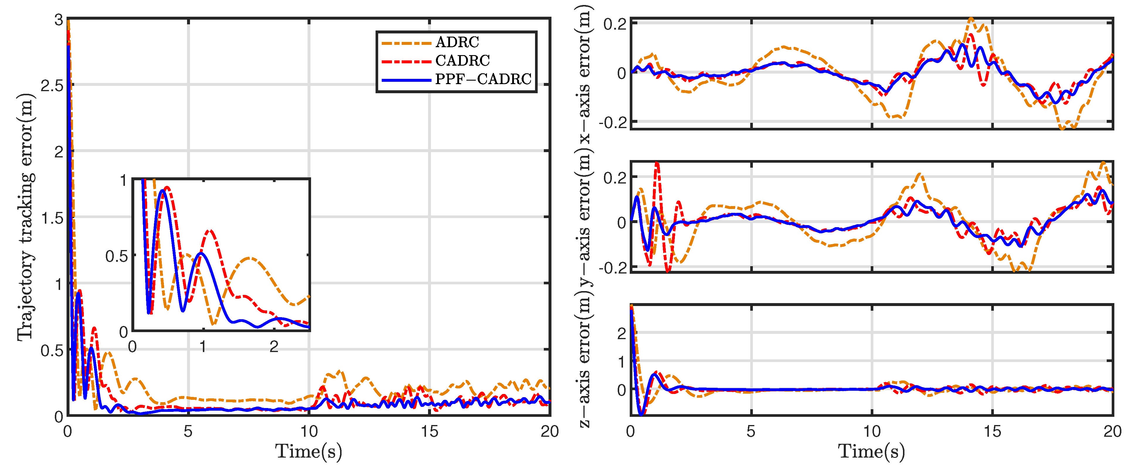
5.1. Quadrotor with Loss of Effectiveness
A typical actuator partial failure scenario was constructed in the simulation: at , a sudden effectiveness degradation occurred in actuator 1, represented by the effectiveness of the actuator .
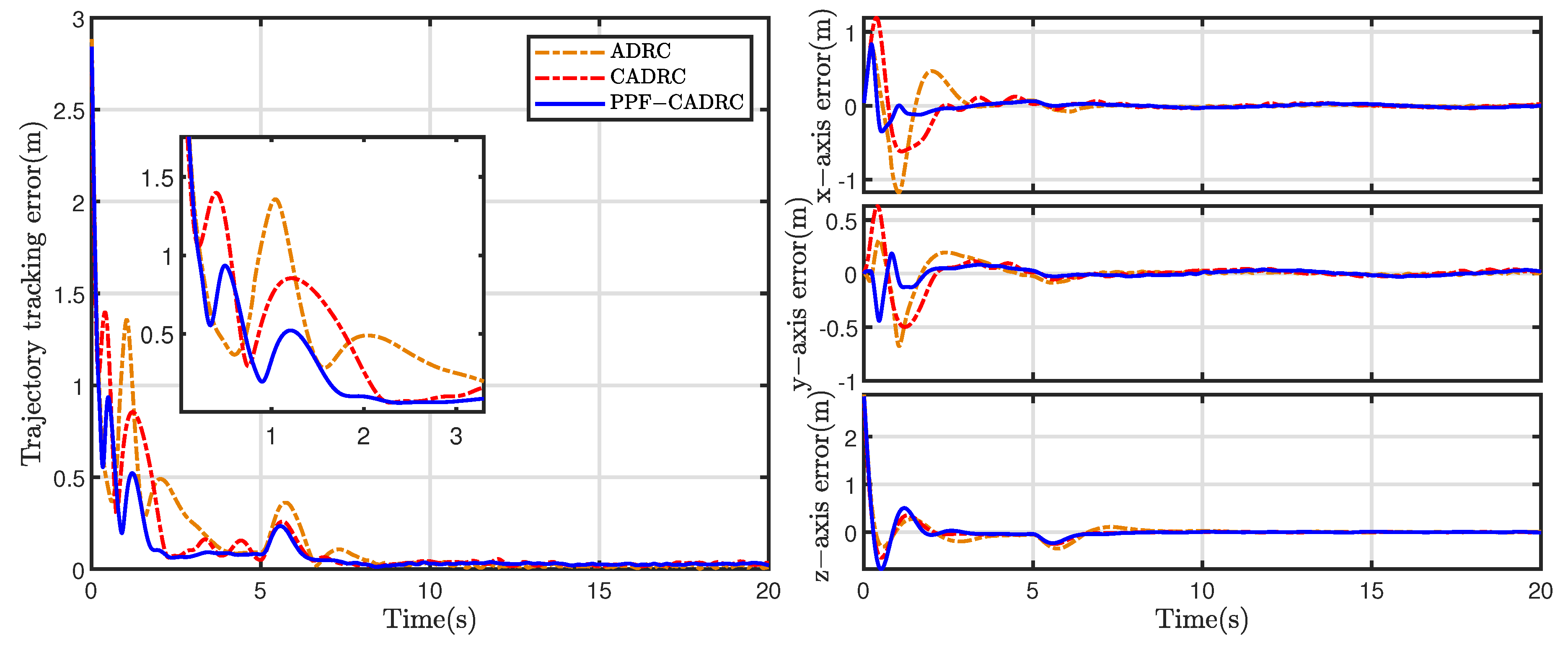
Figure 5 compares the trajectory tracking errors of the quadrotor under actuator effectiveness degradation using ADRC, CADRC, and PPC-CADRC controllers. The root mean square errors (RMSEs) were 0.27 (PPC-CADRC), 0.30 (CADRC), and 0.52 (ADRC) for the respective control systems. Before fault occurrence, all three controllers demonstrated stable tracking capability, while PPC-CADRC exhibited smaller overshoot and faster convergence. When actuator effectiveness degradation occurred after
, PPC-CADRC maintained smaller error amplitude, demonstrating superior disturbance rejection capability.
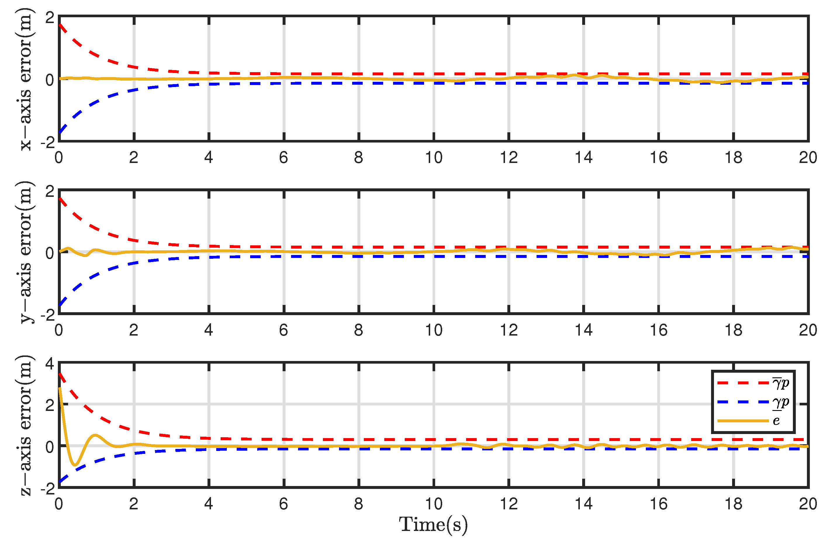
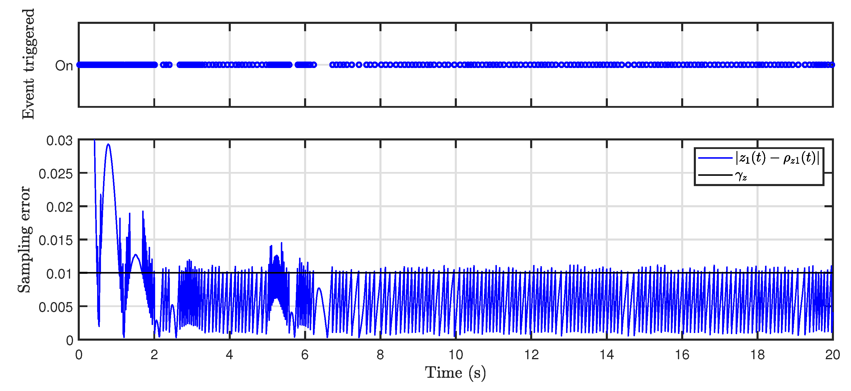
Figure 6 demonstrates the dynamic constraint effect of the prescribed performance function on system error. By introducing the prescribed performance function, the tracking error was strictly confined within boundaries throughout the control process. The error trajectory maintained compliance with all performance requirements throughout both transient and steady phases. This outcome confirms the effectiveness of the performance function while demonstrating its ability to bound system dynamic errors.
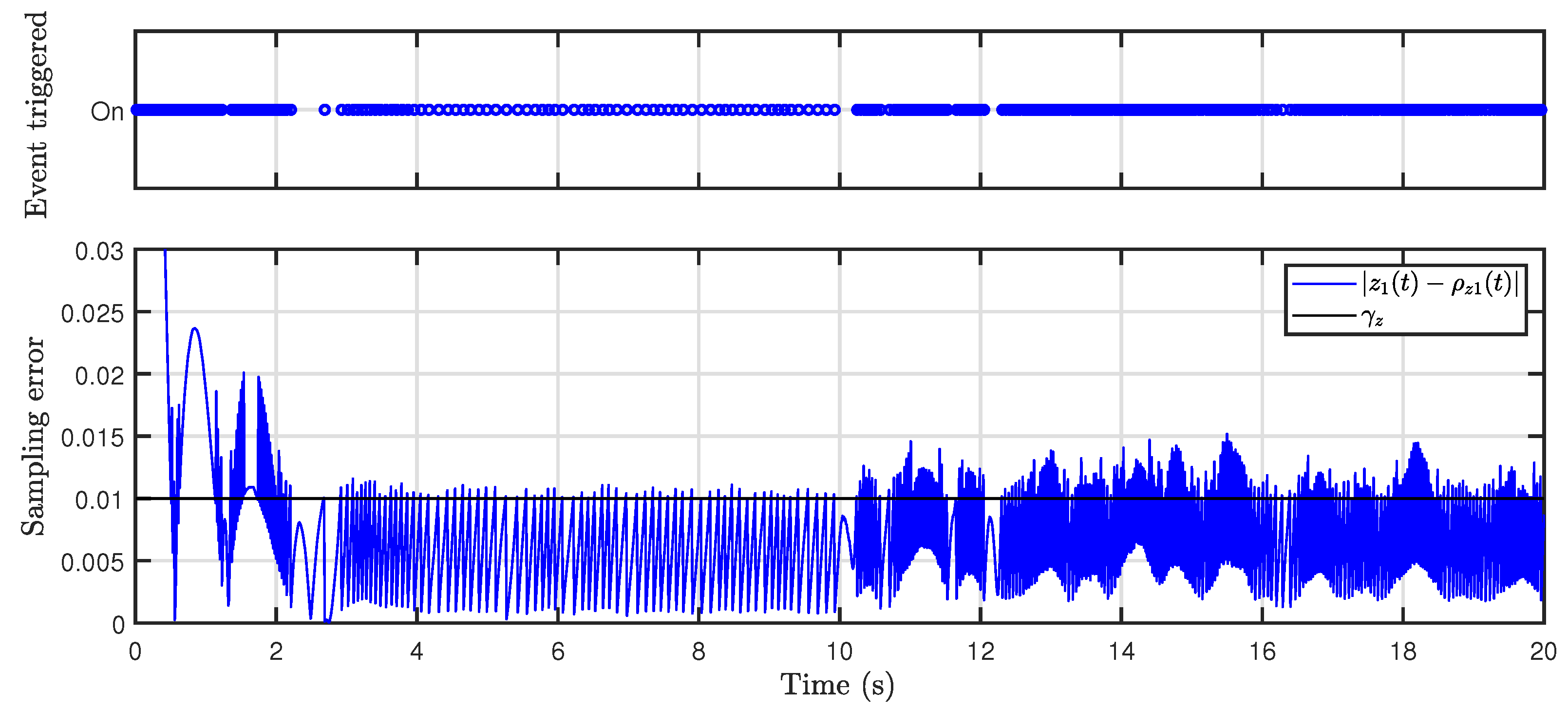
The event-triggered mechanism of the observer was analyzed by taking the displacement
z-axis as an example.
Figure 7 shows the event-triggered moments and sampling errors for the
z-axis observation channel. It can be seen that when the sampling error between the sampled value and the actual value was greater than the threshold value, the observer performed a state sampling and information transfer. The event-triggered mechanism reduced
of data transfer compared to the continuous triggering mechanism.
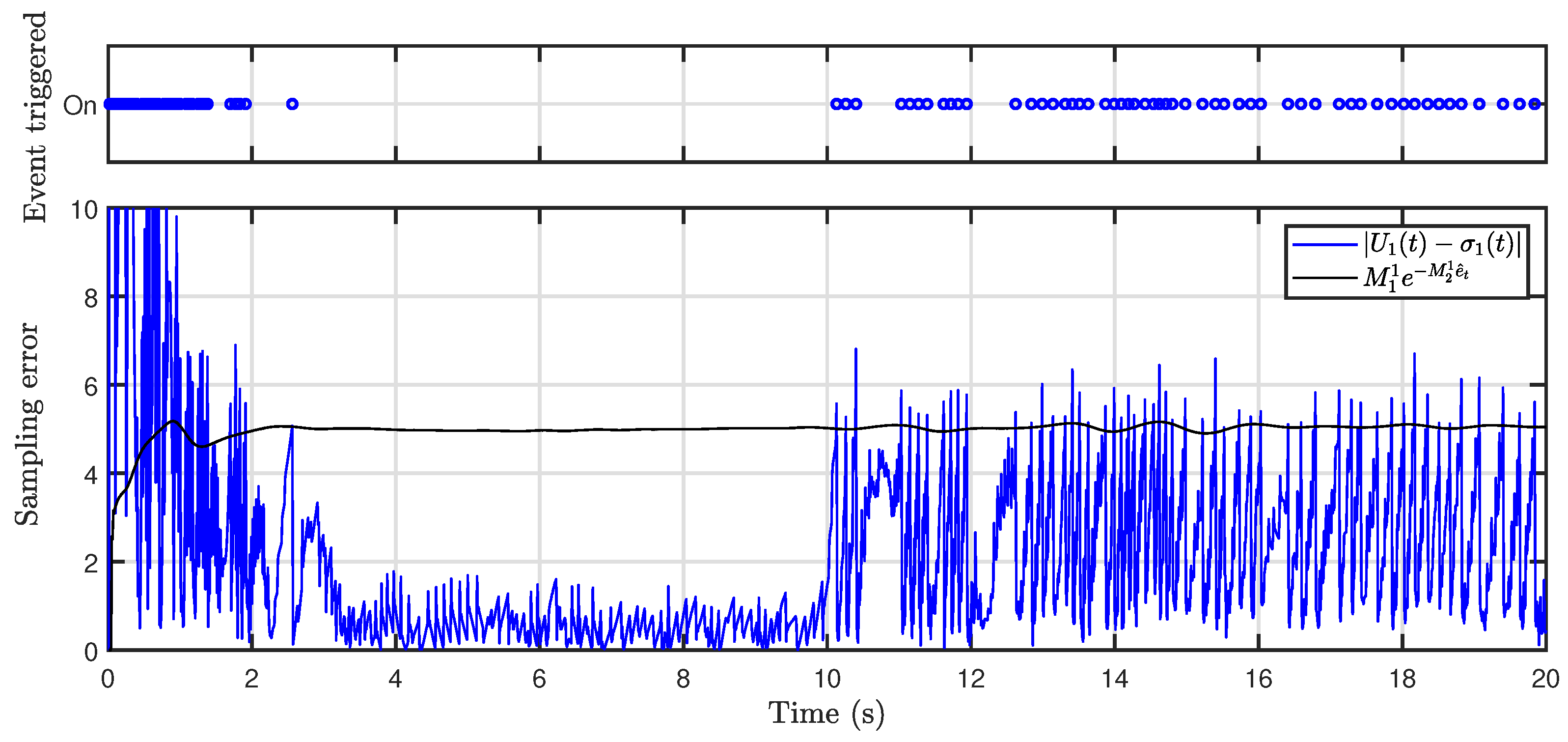
Figure 8 shows the event-triggered instant and sampling error for the control variable
. The results show that a smaller triggering threshold was adopted when the tracking error was large, while a larger threshold was set for smaller errors to reduce event-triggered frequency. This time-varying event-triggered mechanism reduced
of data transfer compared to a continuous triggering mechanism. From
Figure 7 and
Figure 8, it can be observed that when
, the system state changed after the actuator failed, and the frequency of event triggering increased at this time to ensure the control accuracy.
The quadrotor system was simulated under
,
,
, and
effectiveness degradation in actuator 1. The results are presented in
Figure 9. As the failure severity increased, significant growth in trajectory tracking error was observed. Following fault occurrence, the RMSEs were 0.05 (
), 0.06 (
), 0.09 (
), and 0.12 (
), respectively. The steady-state error exhibited progressive enlargement with increasing fault severity. However, the controller maintained fundamental tracking capability without complete failure, thereby validating its passive fault-tolerant characteristics.
5.2. Quadrotor with Bias Fault
A scenario with actuator bias faults was constructed for the variable-load quadrotor: actuators 1 and 2 developed bias faults when
, with bias parameters
. The simulation results are shown in the figures.
Figure 10 shows the error of the quadrotor trajectory tracking.
Figure 11 shows the instant when the observer event was triggered, while
Figure 12 shows the instant when the controller was triggered.
Figure 10 demonstrates that the PPC-CADRC exhibited superior disturbance rejection after fault occurrence. During the post-fault period, the RMSEs were 0.05 (PPC-CADRC), 0.06 (CADRC), and 0.09 (ADRC) for the respective control systems. The designed controller showed better performance with smaller overshoot and faster settling time. When actuator bias failure occurred at
, the PPC-CADRC maintained smaller oscillations and demonstrated enhanced robustness.
Figure 11 shows the event-triggered instant and sampling error for the
z-axis observation channel. The event-triggered mechanism reduced
of the data transfer compared to the continuous triggering mechanism.
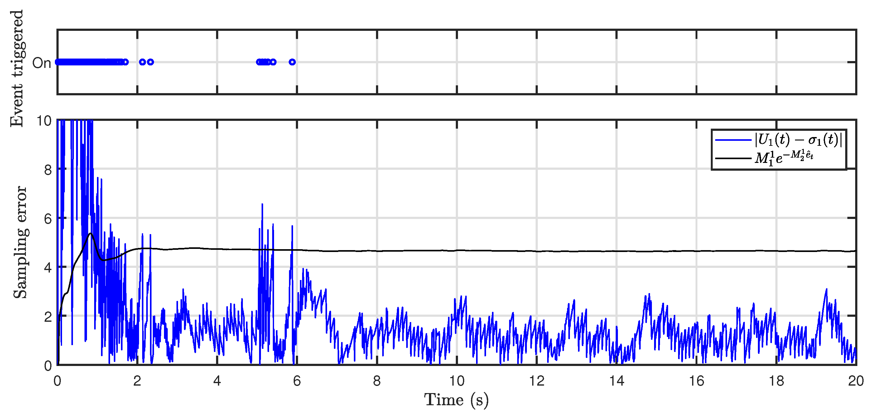
Figure 12 shows the event-triggered instant and sampling error for the control variable
. This time-varying event-triggered mechanism reduced
of data transfer. From the figures, we can see that when the system was in the time period of high error of
–
, both the observer and controller event-triggered mechanisms transmitted data more frequently, ensuring the effectiveness of the control system and saving the computational resources of the quadrotor at the same time.
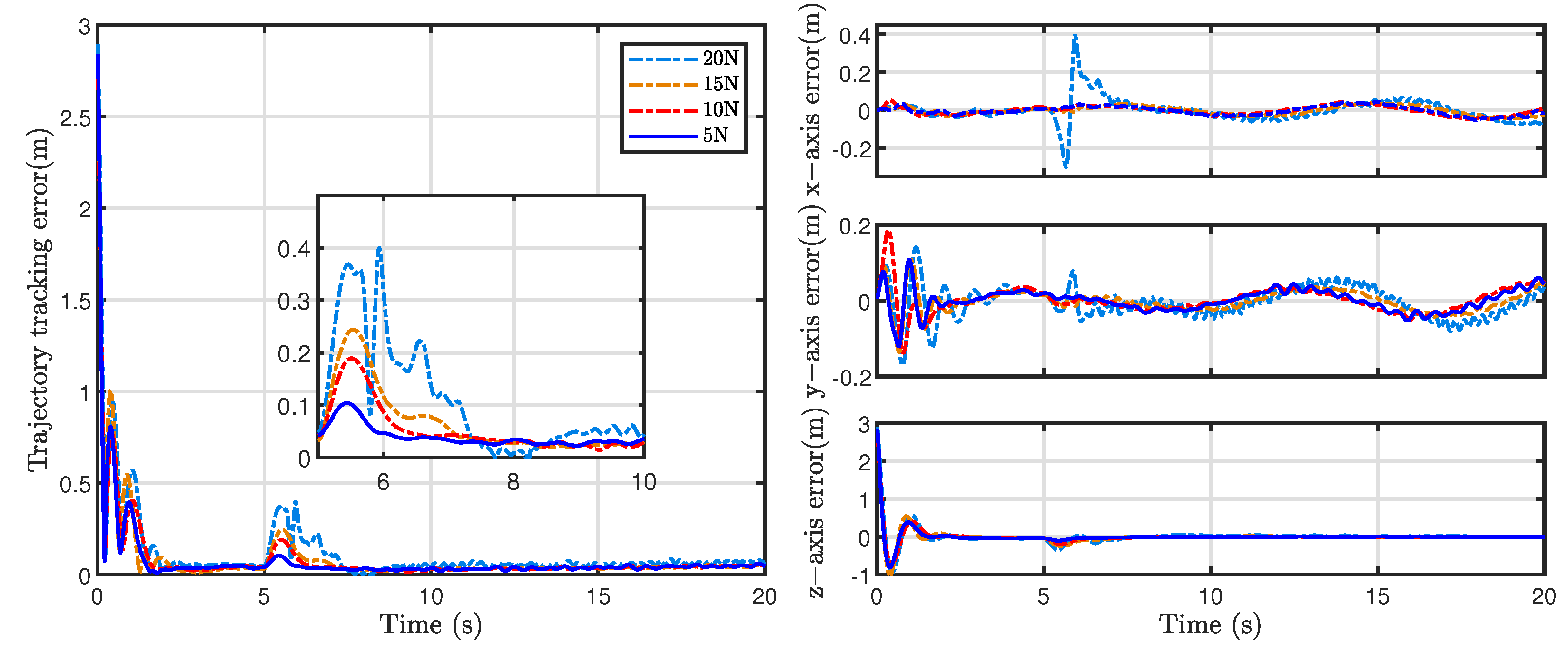
Simulations were performed on the quadrotor with bias faults of 5 N, 10 N, 15 N, and 20 N applied to actuators 1 and 2. The results are presented in
Figure 13. As the bias fault magnitude increased from 5 N to 20 N, tracking error amplitudes showed significant growth. During the post-fault period, the RMSEs were 0.04 (5 N), 0.05 (10 N), 0.06 (15 N), and 0.10 (20 N), respectively. All bias conditions induced a transient overshoot. Under mild fault conditions, the overshoot remained small with rapid recovery. In contrast, the 20 N fault case exhibited a prolonged overshoot duration. However, the trajectory-tracking capability was ultimately recovered in these scenarios.
6. Conclusions
This research focused on fault-tolerant control for a variable-load quadrotor with actuator failures, presenting a novel ADRC method with prescribed performance. The developed dynamic model considered various failures. A cascaded ESO precisely estimated fault-induced disturbances, and the prescribed performance function dynamically constrained error boundaries to effectively reduce fault-caused overshoot and oscillations. The event-triggered mechanism ensured that system state and control signal updates were executed solely upon the satisfaction of predefined triggering conditions. This design maintains control performance while significantly reducing computational resource consumption.
Theoretical analysis confirmed the closed-loop system stability. The simulation results verified that PPC-CADRC maintains lower position tracking errors than conventional methods during both partial actuator failures and bias faults, while consistently satisfying prescribed performance constraints. The fault-tolerant control in this study primarily relied on ESOs for disturbance estimation and compensation to achieve passive fault tolerance. However, its capabilities in fault-type identification and early-warning mechanisms require further enhancement. The current findings are based on an idealized simulation environment and lack validation on a physical platform. The absence of experimental verification may affect the robustness of the algorithm in real-world scenarios.
Future research could explore intelligent fault diagnosis methods based on multi-source information fusion, analyzing multi-dimensional sensor data including motor current, vibration signals, and temperature through deep learning algorithms to enable early fault detection and precise classification. Regarding the modeling assumptions for variable payloads and asymmetric configurations, future work will prioritize the development of a physical test platform. This platform will experimentally validate control stability under such complex conditions. Additionally, it will verify algorithm performance during dynamic load variations and injected fault scenarios.


